The book is laid out for the paper chosen above, and the print dialog will follow it,
so pick the paper here rather than there. Turn background graphics on
so the cover photograph prints, and leave margins at their default. The page numbers
and the chapter running heads are drawn by the browser into the page margins, so they
exist only on paper: check the print preview rather than this screen for them, and turn
Headers and footers off there so Chrome's own furniture does not crowd
them out. Chrome and Edge print them, Safari and Firefox print the same book without
them.
new build
Glen-L Hot Rod
Hot Rod
Paul Kane · 2004 to 2025
A build log
Glen-L Hot Rod
Hot Rod
kept by Paul Kane
2004 to 2025
The boat
Hot Rod
Designer
Glen-L Marine
Length overall
16′ 6″ (5.03 m)
Beam
6′ 11″ (2.11 m)
Construction
plywood on frame
Started
26 March 2004
Built by
Paul Kane
What it took
By the numbers
97
Days written up
369
Photographs
8,237
Words written
The work
Contents
01Strongback & Molds
Mar 2004
02Fairing & Sanding
Jun 2004
03Paint & Finish
Aug 2004
04Hull Panels
Feb 2005
05Systems
Mar 2005
06Glassing & Epoxy
Mar 2006
07Trailer & Gear
Aug 2006
08Brightwork & Varnish
Dec 2006
09Deck & Coamings
Feb 2007
10Hardware & Fit-Out
Dec 2007
11Sea Trials & Shakedown
Apr 2008
Chapter 01
Strongback & Molds
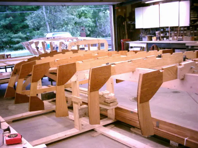
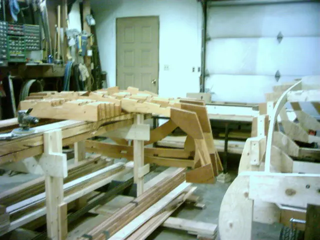
Building the strongback or ladder frame and setting up station molds.
10 daysfrom March 2004
26 Mar 2004Strongback & Molds
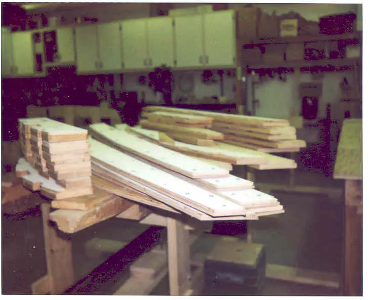
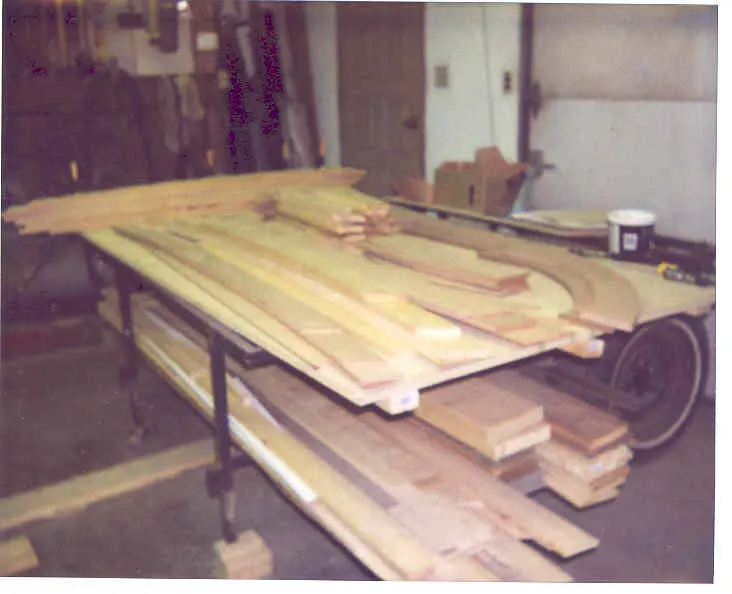
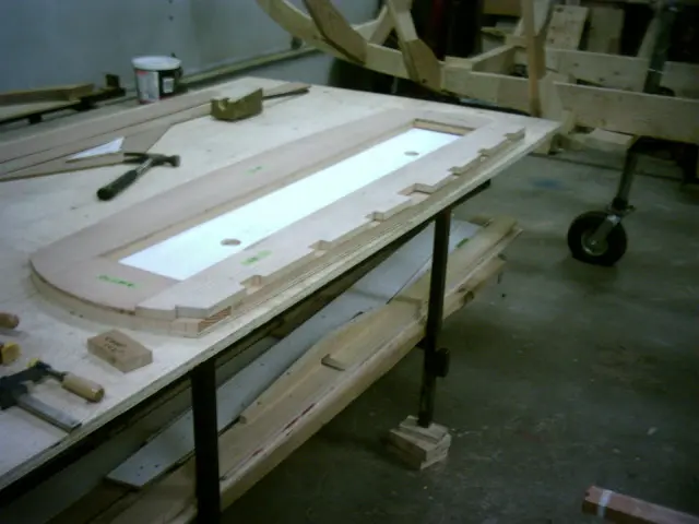
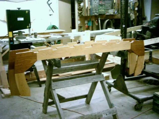
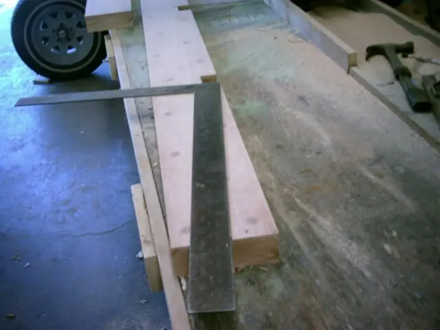
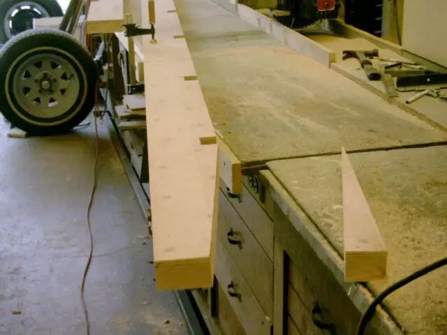
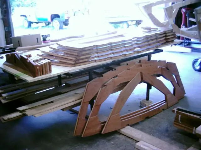
The templates for the bottom frames, laminations and floor timbers were screwed to Douglas Fir stock and cut on the band
The templates for the bottom frames, laminations and floor timbers were screwed to Douglas Fir stock and cut on the bandsaw to within 1/8" of the template. Pieces were then trimmed on the router table using a trim bit.
9 Apr 2004
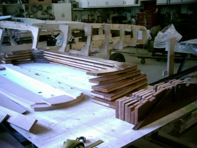
All pieces trimmed on the router table equipped with a top-bearing flush trim bit
All pieces trimmed on the router table equipped with a top-bearing flush trim bit.
Chapter 02
Fairing & Sanding
The long one. Fairing compound, longboards, and the sanding nobody photographs enough.
14 daysfrom June 2004
8 Jun 2004Fairing & Sanding
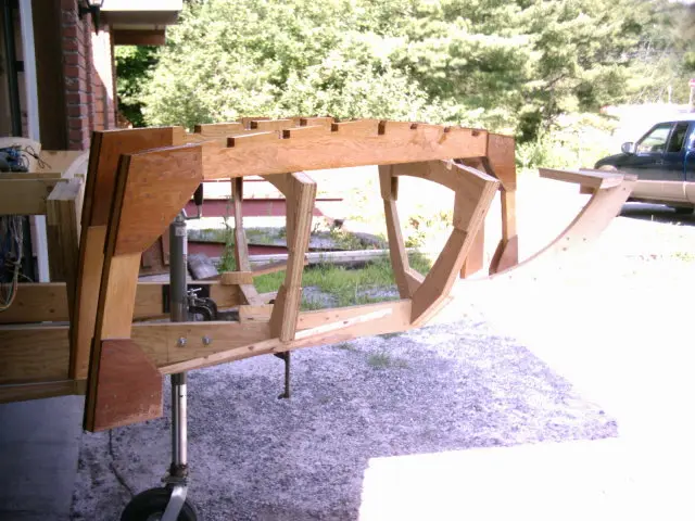
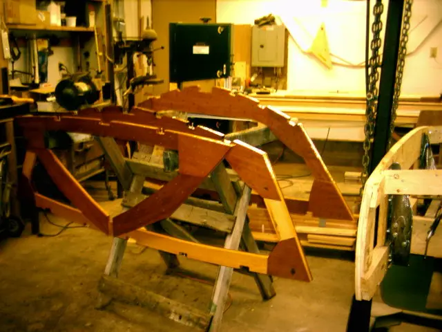
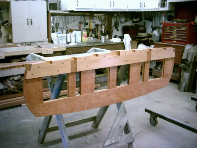
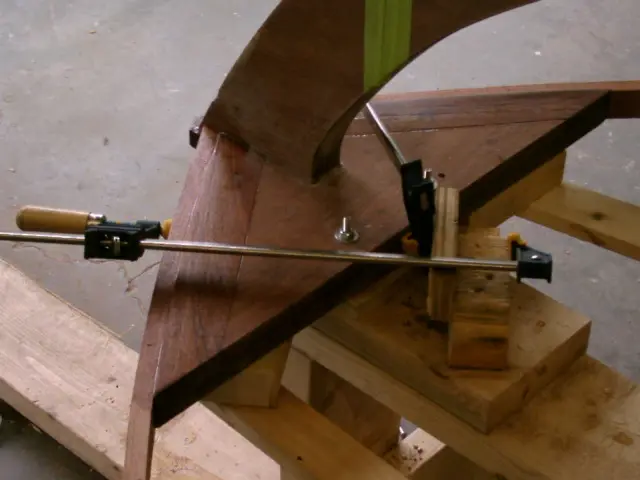
Frame and floor timber assembly completed
Frame and floor timber assembly completed.
Assembling transom.
Epoxy barrier coating frames #1 and #2...
#3 and #4...
#6, #7 and #8. A total of three coats was applied with wet sanding between coats to remove any amine blush from the epoxy.
Laminating motor stringers.
Laying out the motor stringer frame notches.
Cutting the motor stringer frame notches.
Laying out motor stringer bevel.
Cut completed.
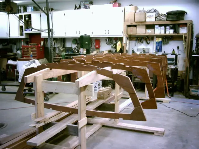
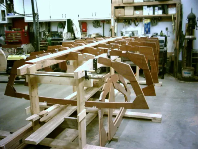
All frames completed.
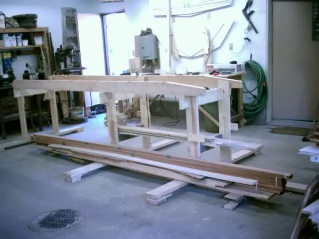
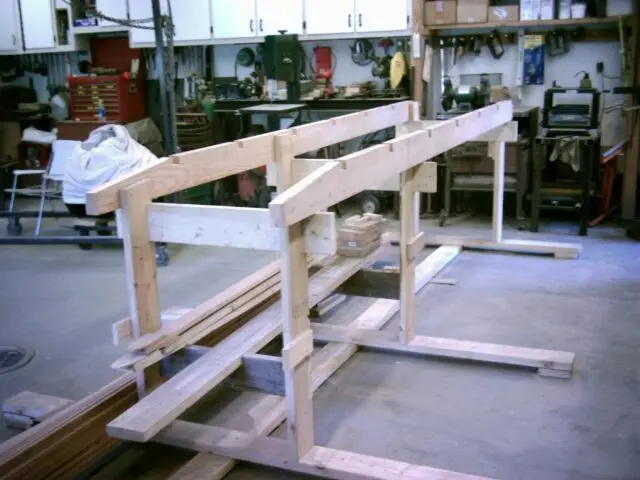
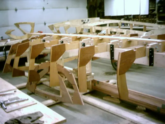
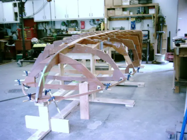
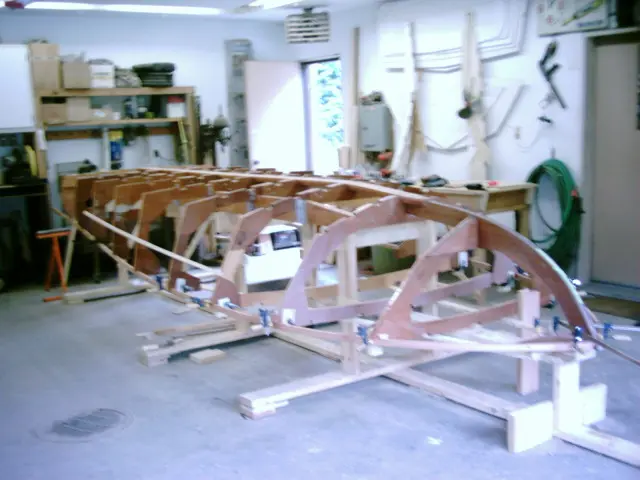
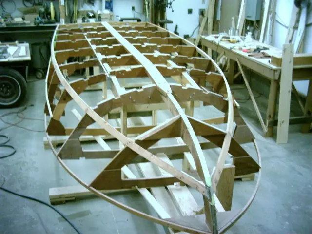
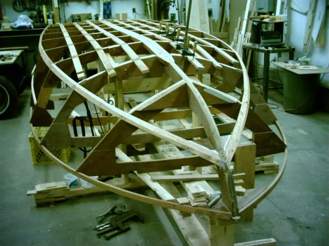
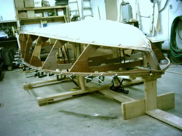
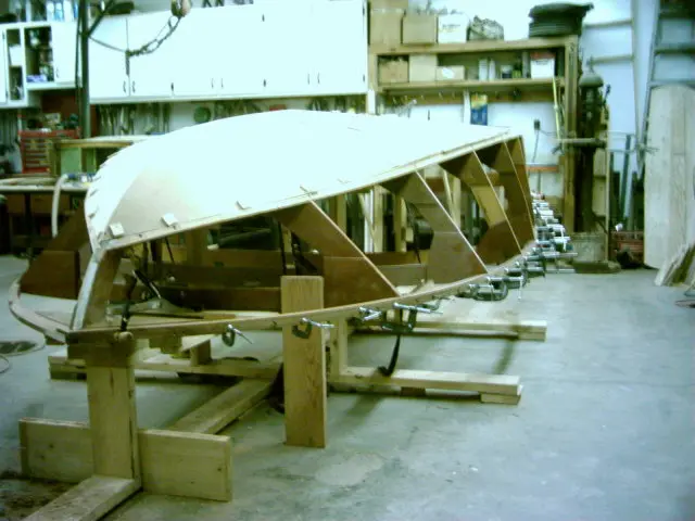
Since the hull is only 28" deep, the setup jig height was increased so that the top of the frames were 16" off the floor. This raises the boat to a more convenient work height and provides increased clearance for cutting the frame sheer notches and fairing the sheer clamps.
A third leg was added between frame # 4 and # 5. This prevents stringer and frame movement when the chine and sheer are sprung in.
Frames fitted to motor stringers.
24 Jul 2004Strongback & Molds
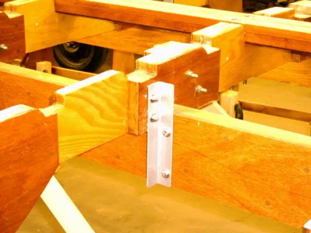
Frame clips were fabricated from 1-1/2" angle iron
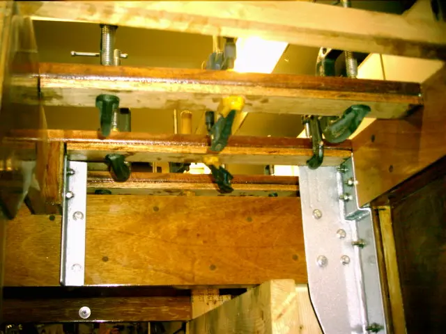
Frame clips were fabricated from 1-1/2" angle iron. The floor timbers were bolted to the frames which were in turn bolted to the motor stringers.
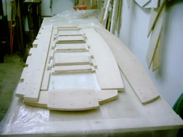
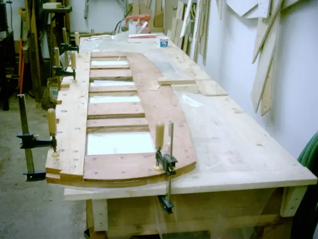
To ensure assembly accuracy, the transom pieces will be overlaid on the transom template.
All pieces ready for lamination.
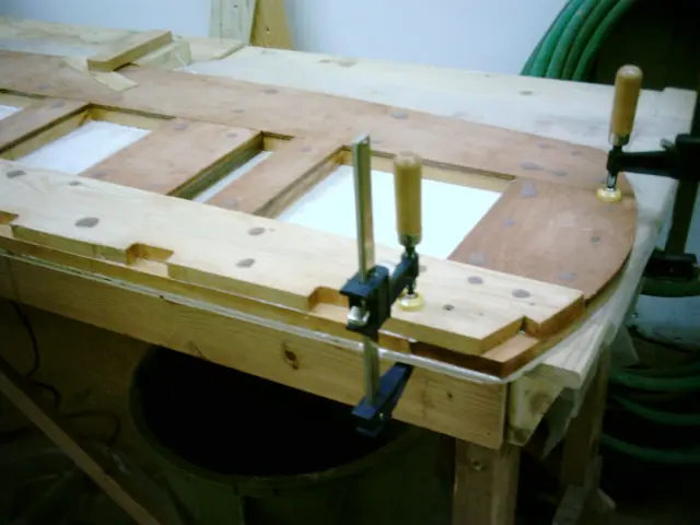
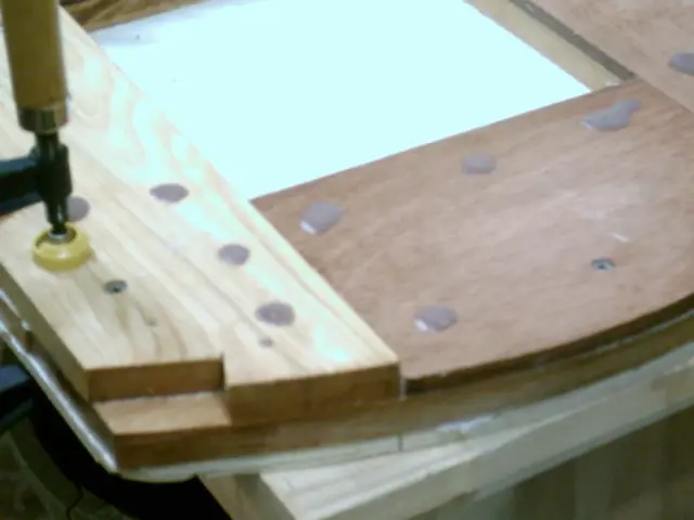
Filling the screw holes.
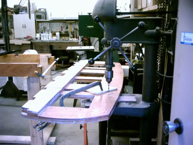
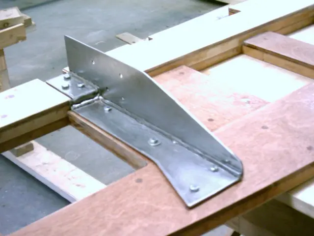
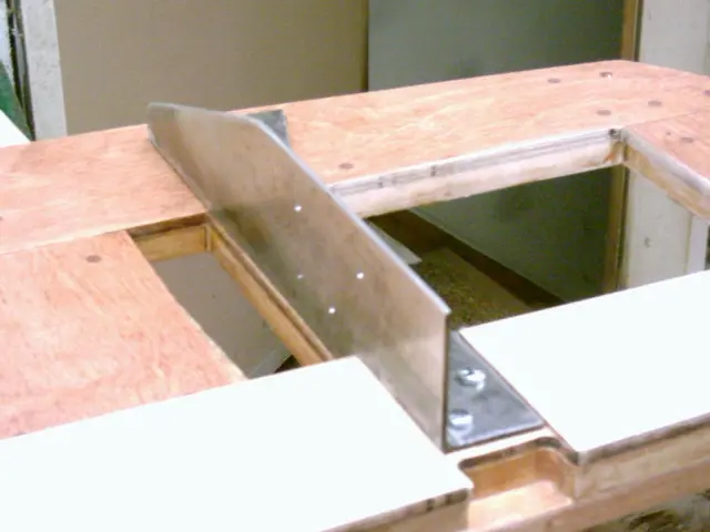
Drilling holes for the transom brackets.
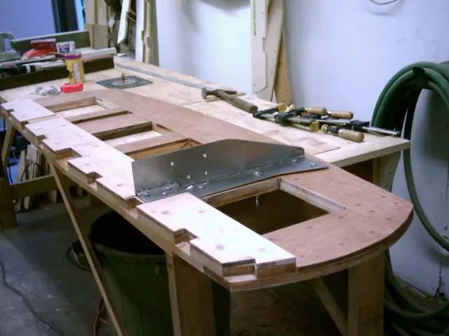
Transom brackets were fabricated from 1/8" flat stock.
Bracket top was flared to allow the installation of two bolts instead of one.
Three coats of epoxy complete the transom.
Chapter 03
Paint & Finish
Primer, topcoat, bottom paint, boot stripe, lettering.
12 daysfrom August 2004
12 Aug 2004Paint & Finish
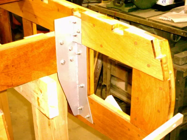
Transom bracket painted and installed
Transom bracket painted and installed. Prior to installation, the brackets and frame clips were sandblasted, primed with DuPont 2580CR self-etching urethane primer, base-coated with Imron Urethane white and topcoated with Imron Urethane metallic silver.
Fitting the sheer clamps to the breasthook. The breasthook was bulit up using two pieces of 1" x 3" mahogany stock and 3/4" marine plywood. The strips will provide a stable landing for the sheer clamp screws.
7 Sep 2004Strongback & Molds
Installing the sheer clamps
Installing the sheer clamps. Two strips of 5/8" x 1-1/4" mahogany will be used per side.
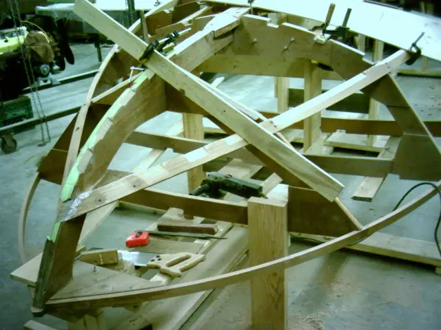
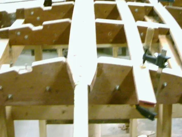
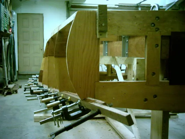
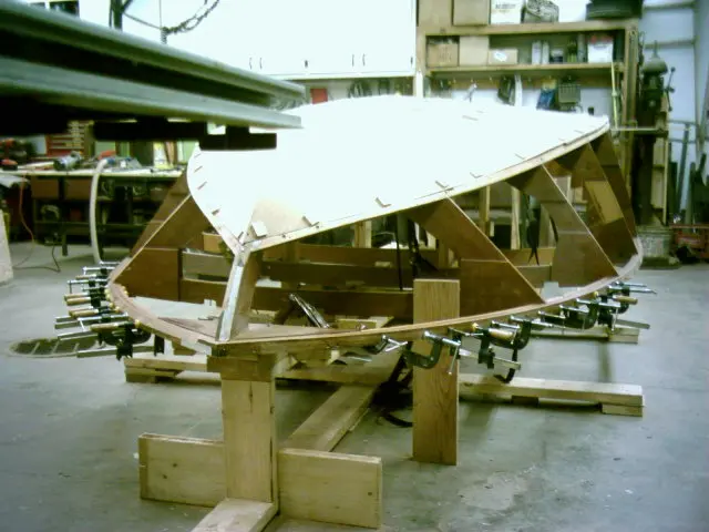
Although not detailed in the plans, the chine blocking was made from two pieces of 3/4" marine plywood. The sides were bevelled at 30 degrees and a notch was cut to fit around the stem. This is definitely a trial and error project. Much time will be saved when fitting the chine logs to the blocking.
Glued...
Screwed...
Installed.
The chine log was wrapped with waxed paper to prevent it from being glued to the blocking.
14 Sep 2004Strongback & Molds
Fitting the chine
Fitting the chine.
19 Sep 2004Strongback & Molds
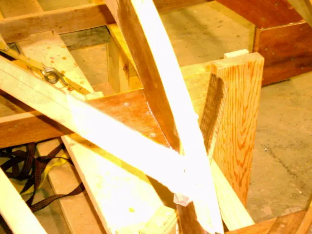
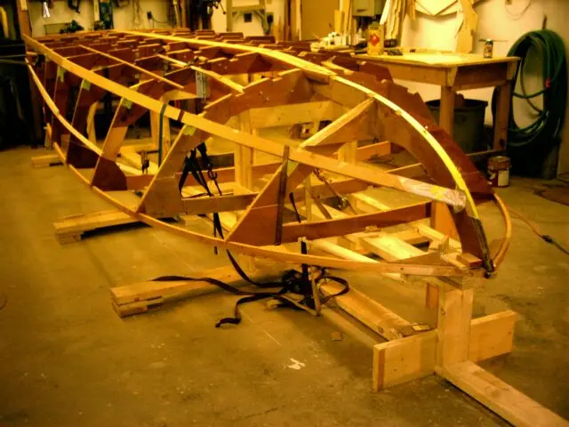
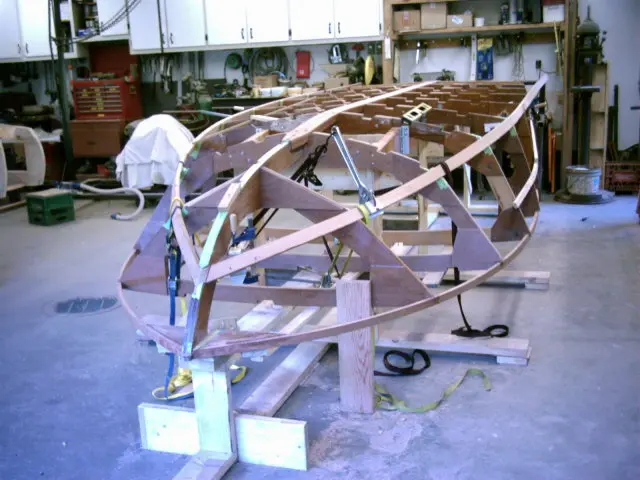
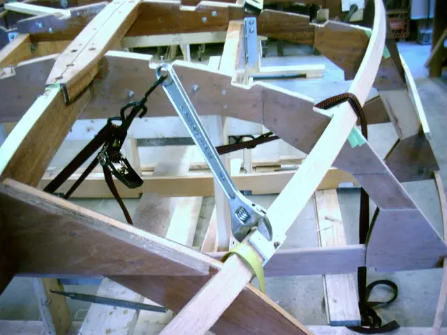
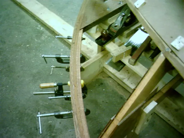
A large crescent wrench and a ratchet strap was used to twist the top of the chine inward towards the keel
A large crescent wrench and a ratchet strap was used to twist the top of the chine inward towards the keel. Laying a straightedge from the sheer to the chine will indicate when sufficient twist is attained.
6 Jan 2005Fairing & Sanding
The second sheer clamp laminations are yet to be installed
The second sheer clamp laminations are yet to be installed. Notes on fitting the chine Photo courtesy of Glen-L Marine Designs The photo above illustrates a plywood fixture we have found helpful to determine the position of the chine on the stem side. Keep in mind what has been stated in the foregoing. The bottom and side must mate to the stem and chine on a continuous surface. The chine can't be located on the stem so that the stem/chine junction cannot be faired to a flat plane. Take small pieces of plywood and simulate the side and bottom joining on the stem to help visualize what the finished junction will look like. Source : Designer's Notebook: Fitting the chine - WebLetter 49
Fairing the stem and chine using the 'Rabl' method. The method is depicted in the following plate : From the book Boatbuilding with Plywood by Glen L. Witt For a complete description of the fairing method, follow the links below : Designer's Notebook : Fairing by the "Rabl Method" : Article by Glen L. Witt. Boatbuilding with Plywood : Book by Glen L. Witt.
Compare the unfaired side (left) to the faired side (right).
Here you can see unfaired frame # 7 (background) and the faired frame (foreground).
15 Jan 2005Fairing & Sanding
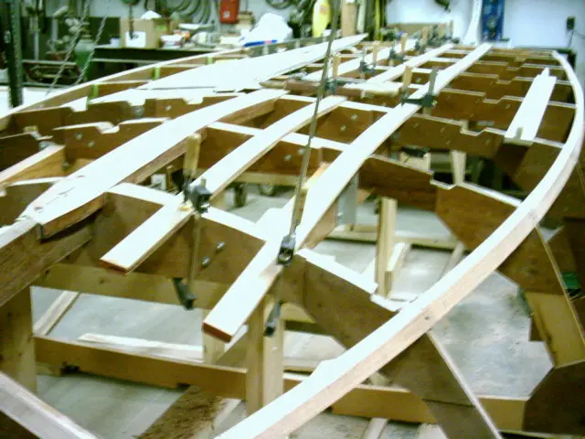
Installing the battens and fairing
Installing the battens and fairing.
28 Jan 2005Fairing & Sanding
We'll be sheeting with the optional 1/2" botom in the flatter aft area and two layers of 1/4" in the forward section
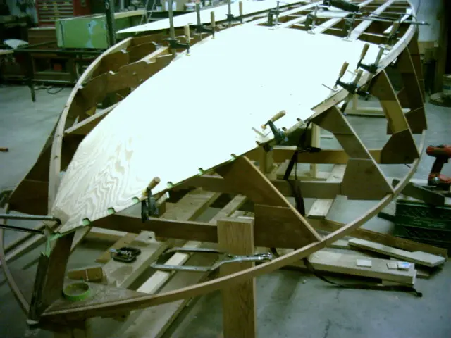
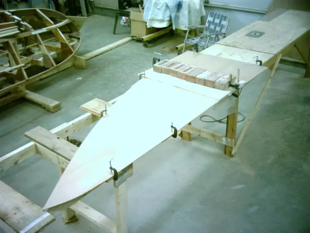
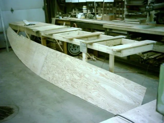
We'll be sheeting with the optional 1/2" botom in the flatter aft area and two layers of 1/4" in the forward section. A template for the first bottom layer is being fitted.
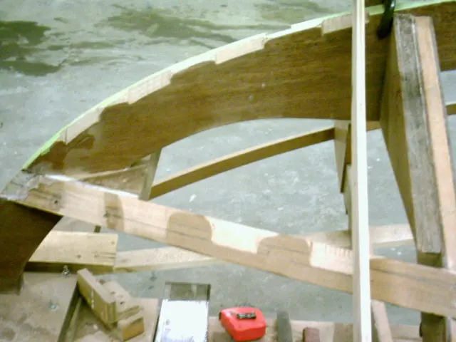
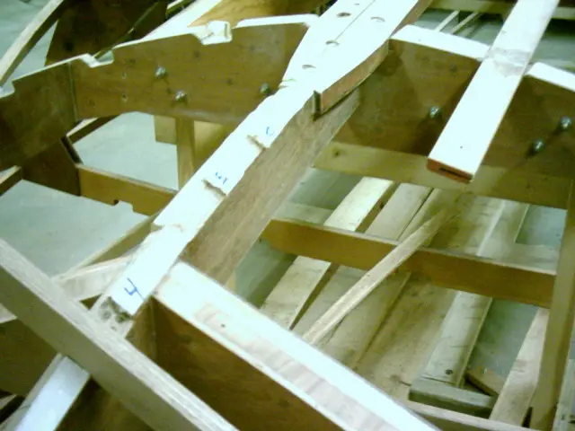
The chine was covered in masking tape and the bottom/side planking junction was marked with a pencil. Using a pneumatic die grinder outfitted with a 1/2" deburring rasp makes quick work of cutting a series of 'mouseholes' every six inches or so along the panel's edge. Trim the slots back until the transition line is visible.
Note the cleft to the right of the last slot. From this point aft, the bottom planking will be faired flush with the side of the chine.
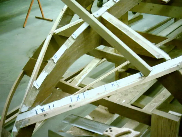
A thin flexible batten is sprung and clamped along the panel's slots before marking with a pencil.
Remove the clamps and trim to size. Several methods for handling thickness variations between side and bottom planking at junctions over the chine log are depicted in the following diagram. We chose to recess the first layer of bottom plywood into the chine. See the bottom right drawing labelled Double planking forward portion recessed chine. Methods for handling thickness variations between side and bottom planking at junctions over chine log. Drawing courtesy of Glen-L Marine Designs
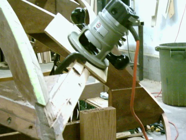
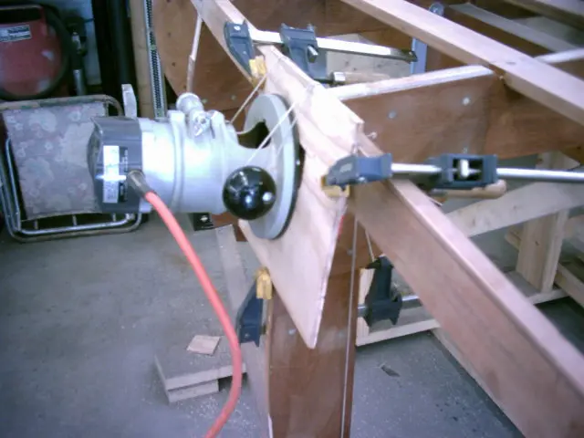
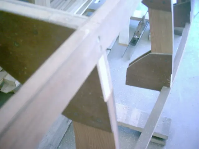
A router was used to recess the forward portion of the chine.
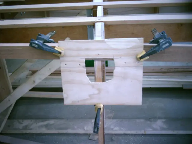
A simple jig made from a piece of 1/4" plywood is used to form a steady base for the router.
Fairing the stem with the 'Rabl' method. The following link explains how it's done : Fairing by the "RABL Method" by Glen L. Witt
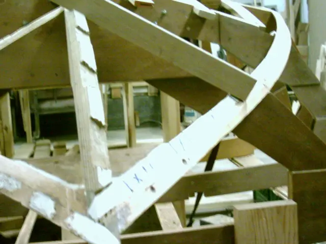
The keel must also be recessed to accomodate the thickness of the plywood. A router is used (freehand) to fair the surface.
The depth of the recess is decreased as it approaches the keel (1/4" deep from mark #1 to #4, 3/16" at #5, 1/8" at #6, 0" at the keel). Install the panel and determine how much should be faired from frame #8.
Chapter 04
Hull Panels
Scarfing plywood, cutting panels, milling strips or planking stock.
11 daysfrom February 2005
4 Feb 2005Hull Panels
The first bottom template (1/4" fir plywood) is screwed to a piece of 1/4" marine plywood and trimmed to size
The first bottom template (1/4" fir plywood) is screwed to a piece of 1/4" marine plywood and trimmed to size.
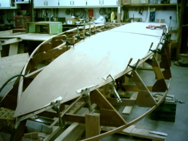
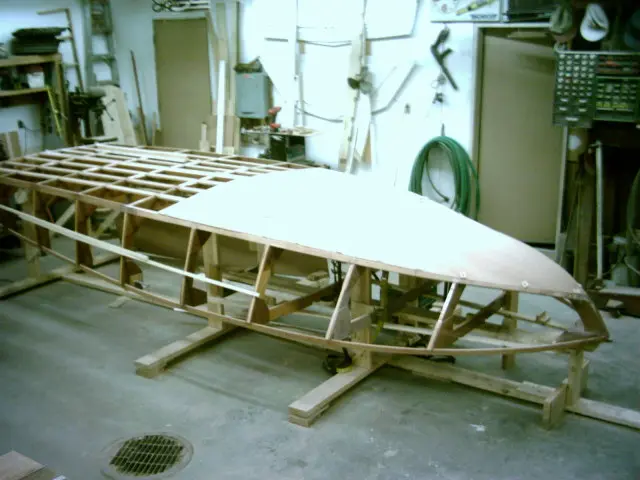
Trial fitting the first bottom. Once installed, it fits flush with the chine from the stem to a point between frames 7 and 8.
A second layer of 1/4" plywood is tacked on to check for fit.
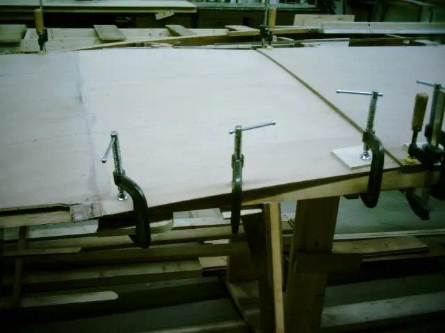
A 26" wide piece of 1/4" marine plywood is scarfed to the first bottom piece. Total length is 8'-6". Click here to see how the scarf was made.
Glued and clamped...
5 Feb 2005Hull Panels
While we're waiting for the bottom panel to fully cure, the side planking template (31" wide x 18' long) is clamped in p
While we're waiting for the bottom panel to fully cure, the side planking template (31" wide x 18' long) is clamped in place.
The two scarfed joints are located midway between frames and in relatively flat areas.
Trimmed.
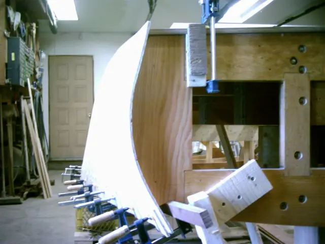
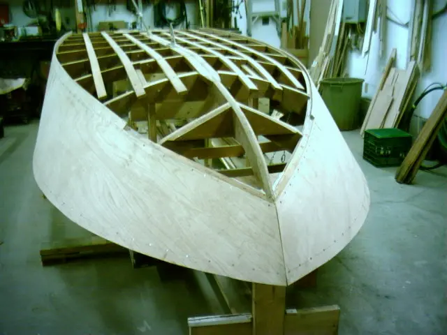
The tumblehome is quite severe at the transom. The fir plywood is barely making the bend. The marine plywood should be much easier to work with.
11 Feb 2005Hull Panels
Fitting the scarfed first bottom panel
Fitting the scarfed first bottom panel.
Since the required panel length is 8'-6" and adding a 6" strip ahead of the butt block is close to frame #4, the scarf joint was moved forward 24" and centered bewteen frames #5 and #6. A butt block between frames #4 and #5 will join the two layers of 1/4" plywood to the aft piece of 1/2" plywood.
Closeup of the epoxied scarf joint.
The panel is left oversized, marked and trimmed.
Screws are driven through plywood spacer washers to spread the screw's clamping force to a larger area.
The port side chine and keel must now be recessed and lowered before fitting the keel junction.
5 Mar 2005Hull Panels
Port chine recessed for first bottom and battens glued
Port chine recessed for first bottom and battens glued.
Port first bottom scarfed and glued. Joint epoxied to check for finish.
Closeup of the finished joint.
First bottom panels ready to be installed.
Side sheeting template.
14 Mar 2005Hull Panels
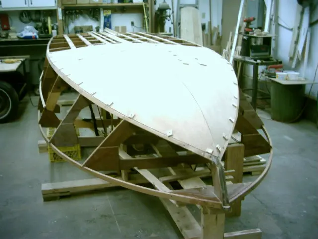
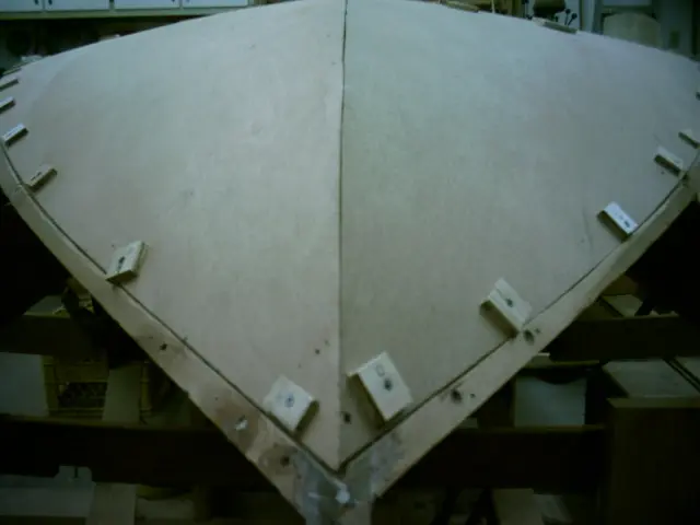
First bottom panels dry-fitted
First bottom panels dry-fitted.
Panels are butted along the stem centerline.
19 Mar 2005
Installing the second sheer clamp lamination
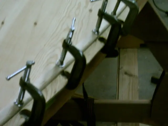
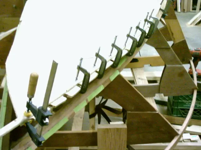
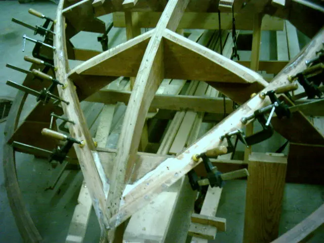
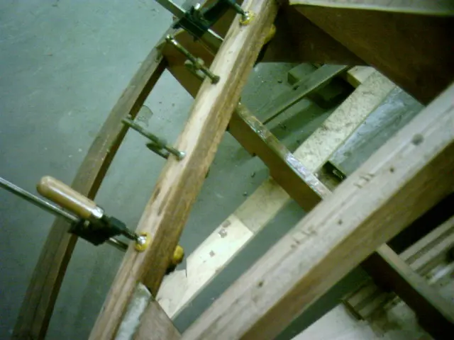
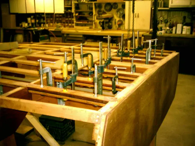
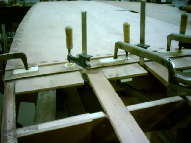
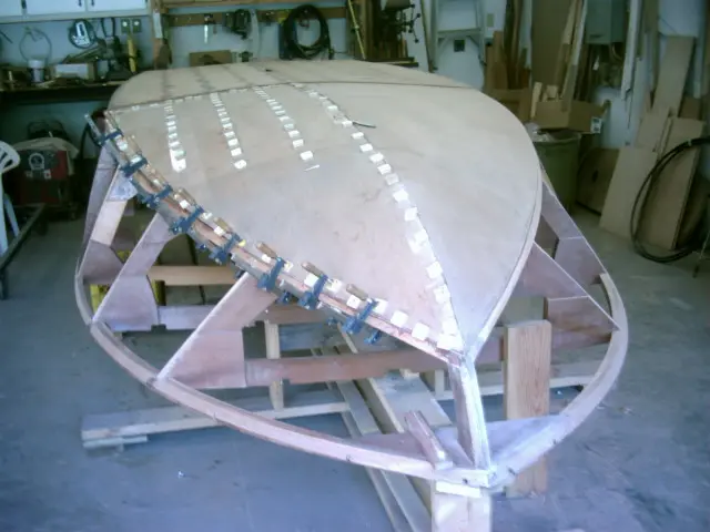
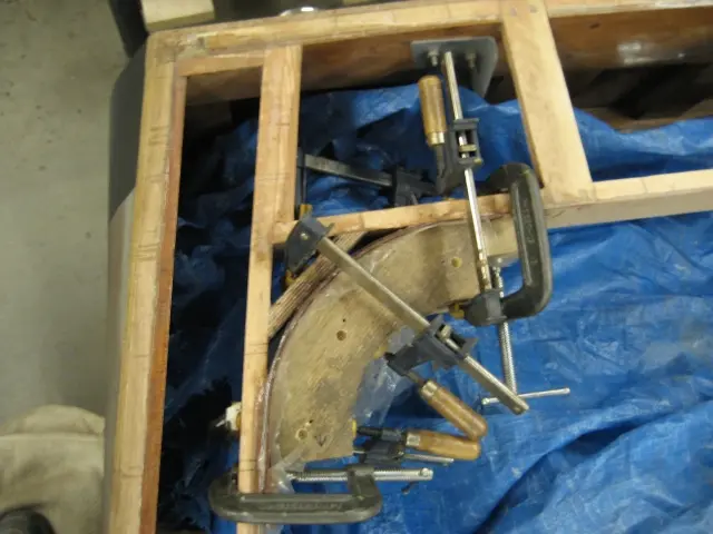
Installing the second sheer clamp lamination. We didn't use any screws to secure the stock, so 29 clamps were needed to do the job.
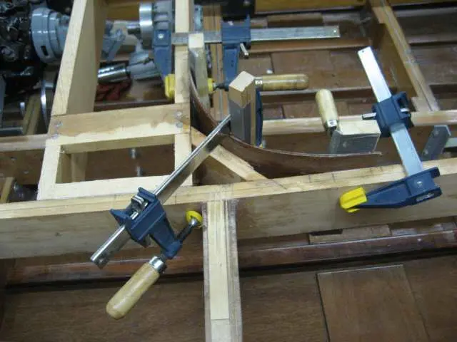
Prior to gluing, the second sheer clamp lamination was aligned with the first lamination and clamped. Finishing nails were used to hold the pieces in alignment. When the laminations are glued, the nails register both pieces to their dry-fit position and prevent the stock from sliding around when clamping pressure is applied.
25 Mar 2005
Gluing the second starboard-side sheer clamp lamination
Gluing the second starboard-side sheer clamp lamination.
26 Mar 2005Strongback & Molds
Gluing the third sheer clamp laminations
Gluing the third sheer clamp laminations.
Transom plywood (3/8" marine) installed.
Chapter 05
Systems
Electrical, plumbing, fuel, steering, pumps, nav lights.
15 daysfrom March 2005
28 Mar 2005Systems
The propeller shaft hole will be drilled prior to sheeting the bottom
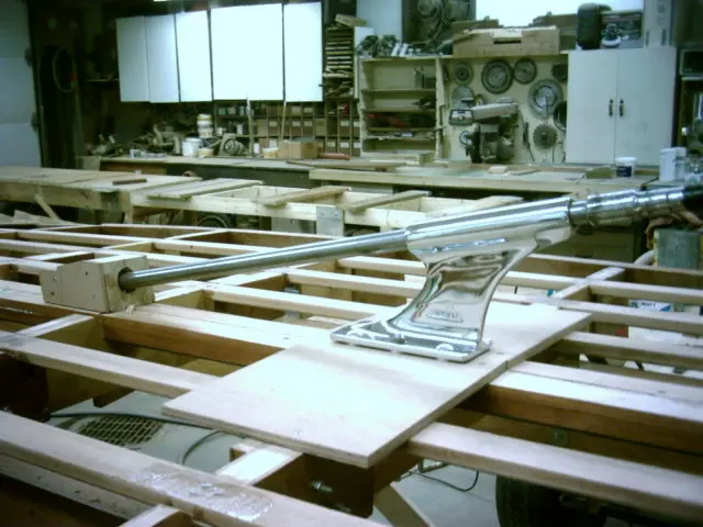
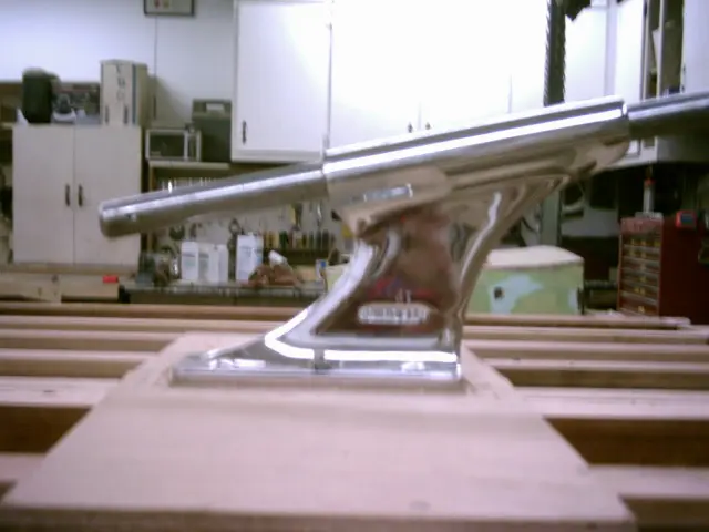
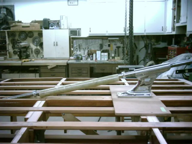
The propeller shaft hole will be drilled prior to sheeting the bottom. Two pieces of scrap plywood were screwed to the keel. Once the strut mounting holes were drilled, a stack of washers under each mounting hole was used to determine how much material had to be removed.
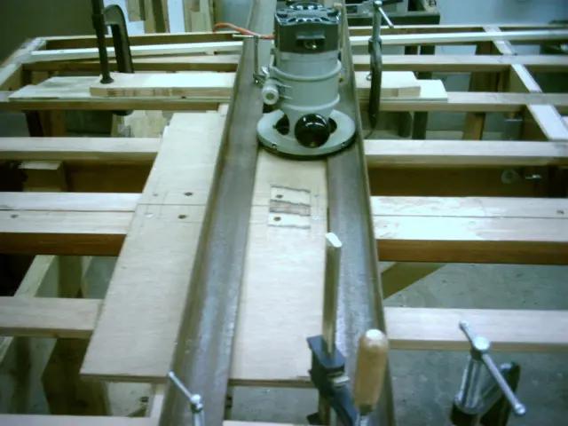
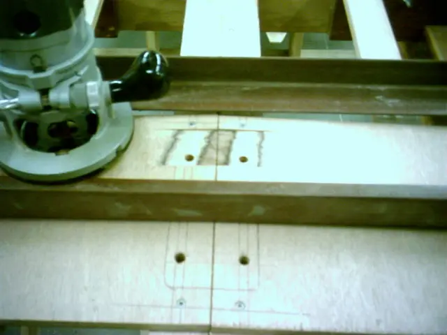
A jig was rigged up to flatten the strut mounting area. The router is run on two parallel lengths of angle iron.
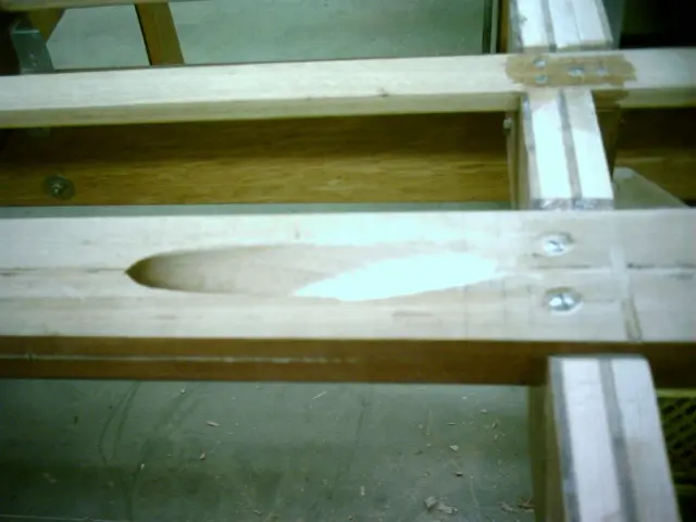
Depth of cut is adjusted to remove enough material so that the strut sits flat on the plywood.
A block plane can now be used to finish the job.
2 Apr 2005Systems
A 1/8" masonite spacer was fabricated and slipped under the strut to simulate the thickness of two layers of fiberglass
A 1/8" masonite spacer was fabricated and slipped under the strut to simulate the thickness of two layers of fiberglass cloth which will eventually cover the hull. The strut was bolted into position and an 8' long piece of 1" round bar was fed through the strut to simulate the propeller shaft.
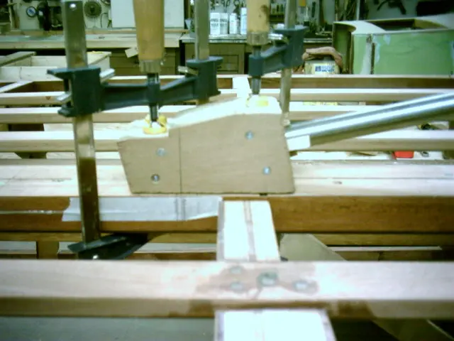
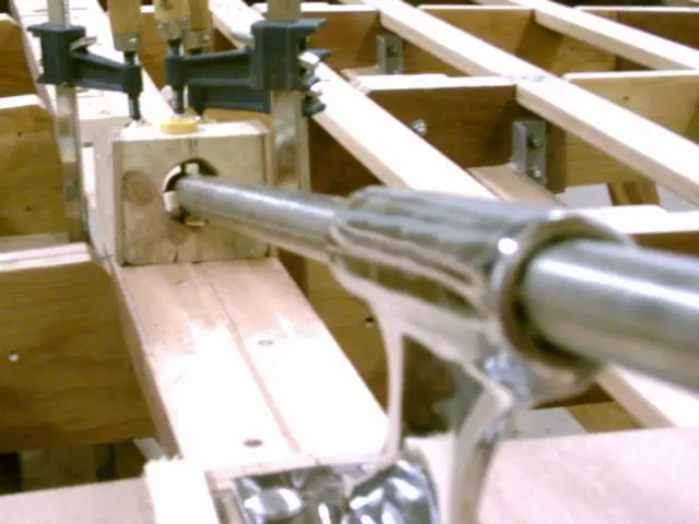
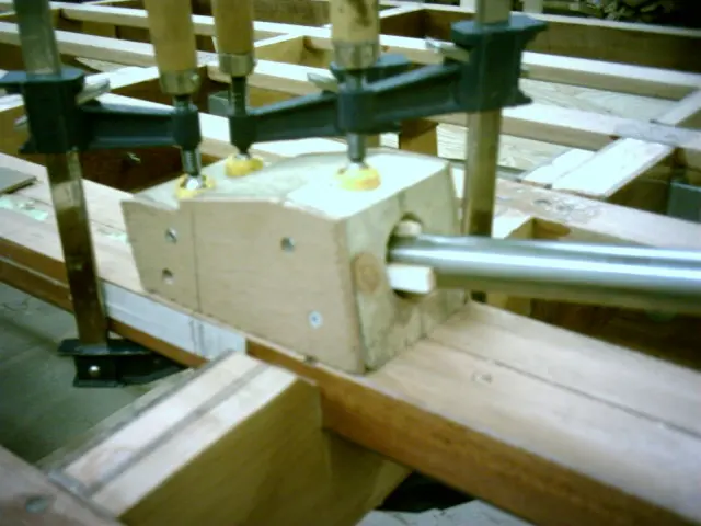
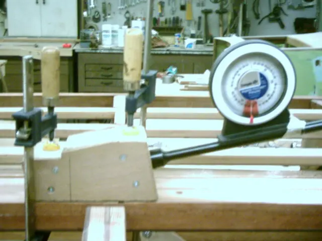
A guide block was loosely clamped to the keel. Click here to see how the guide was made.
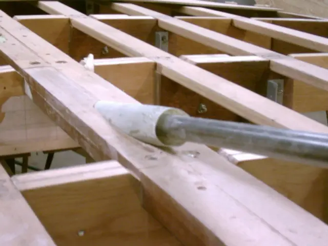
Push the shaft through the guide block until it contacts the keel and mark the point. Shim the shaft until it's centered in the guide block and mark the holesaw entry point. Clamp the guide block.
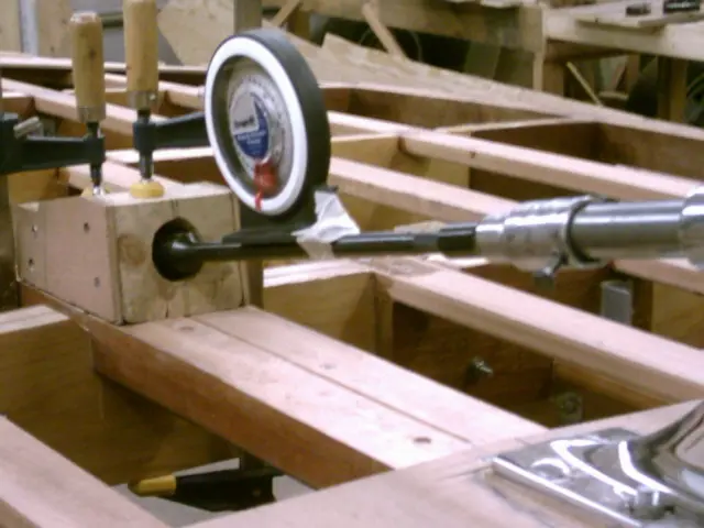
Remove the shaft and insert the boring bar, coupler and holesaw into the guide block. Use an inclinometer to verify the shaft angle is correct before drilling.
Click here to see how the boring bar was made.
The finished shaft hole.
3 Apr 2005Systems
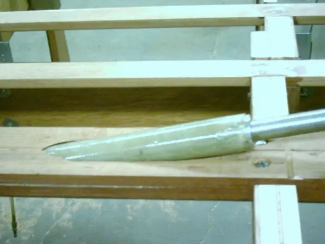
A fiberglass tube was inserted into the shaft hole
A fiberglass tube was inserted into the shaft hole. Click here to see how the tube was made.
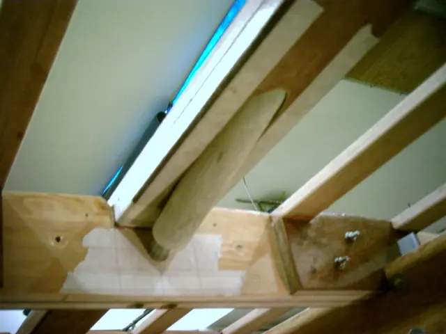
This is a view from inside the boat. An 8' long shaft was fed through the strut and shaft hole. A 1" hole was drlled in frame #4 to position the shaft at 12 degrees.
A 1" ID x 1-5/8" OD rudder shaft collar inserted into each end of the tube will center the shaft in the tube until the epoxy cures.. When the boat is righted, the tube will be ground flush with the keel. Two laminations of fiberglass cloth will be applied to the keel before installing the shaft log.
4 Mar 2006Strongback & Molds
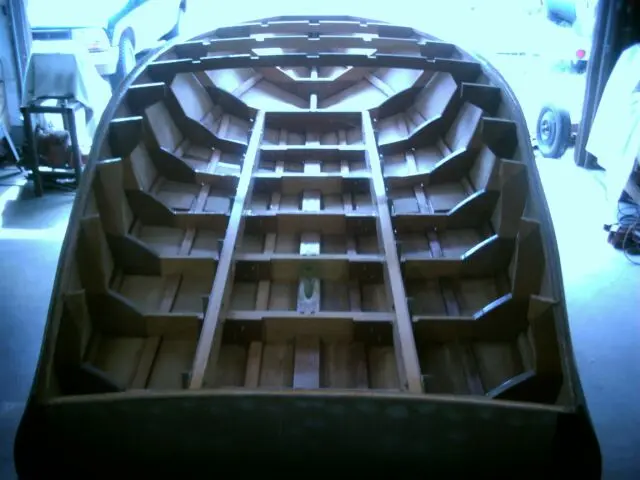
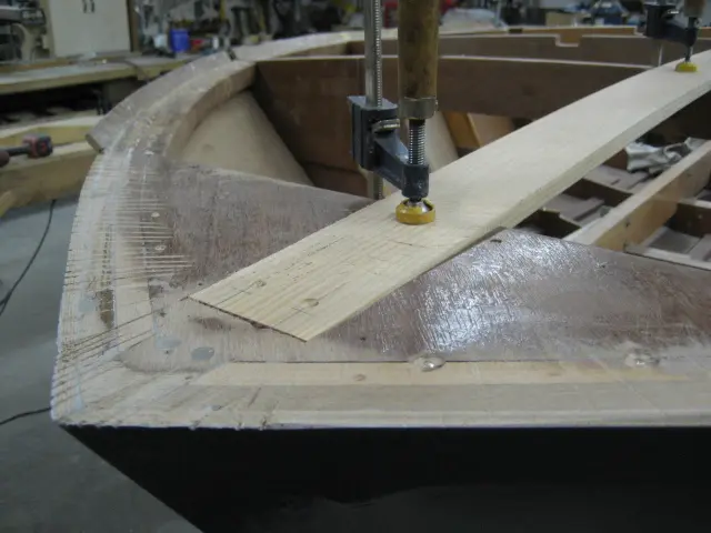
Two layers of 3/8" thick by 2" wide mahogany stock were laminated to the inside chine log surfaces
Two layers of 3/8" thick by 2" wide mahogany stock were laminated to the inside chine log surfaces. This will restore some strength to the members, lock the frames into position and provide additionnal fastening area for the first plywood bottom screws.
A 3/8" thick lamination was added to the rear battens. We'll be cutting 3/8" deep limbers (drainage channels) so additional material must be provided to maintain the batten's integrity.
Here's the view from inside the boat.
9 Mar 2006Fairing & Sanding
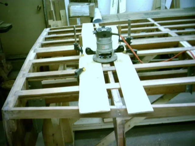
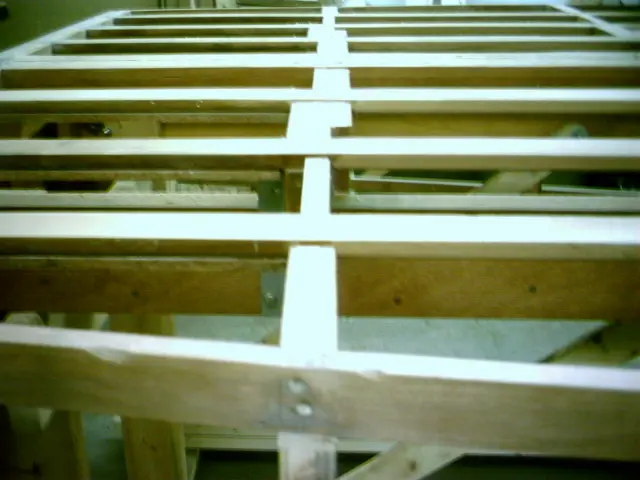
A quick and accurate method of fairing the frames so they'll sit 1/8" below the battens involves running a router over t
A quick and accurate method of fairing the frames so they'll sit 1/8" below the battens involves running a router over two strips of 1/4" plywood clamped to the battens.
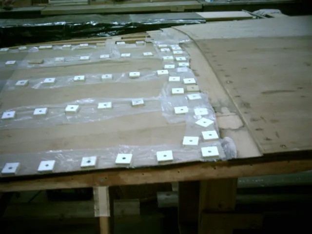
This prevents 'hard spots' from forming on the hull where the frames contact the bottom planking.
Chapter 06
Glassing & Epoxy
Sheathing in cloth, wetting out, fill coats.
6 daysfrom March 2006
12 Mar 2006Glassing & Epoxy
The strut was reinstalled and an 8' long piece of 1" round bar was slipped into it
The strut was reinstalled and an 8' long piece of 1" round bar was slipped into it. Two 1" ID by 1-5/8" OD bushings and the fiberglass tube were slid onto the shaft.
Here's a closeup shot of the tube and bushing.
The bushings were slid into each end of the tube. This will ensure that the tube is centered on the shaft.
The assembly is pushed into the shaft hole. It should be a loose fit. Enough clearance for a coat of thickened epoxy around the tube will be required. If the fit is too tight or if the tube binds in the shaft hole, roll and tape a piece of coarse sandpaper around the tube and rotate it in the shaft hole.
Here's the view from inside the boat. The 1" shaft rests in a 1" diameter hole drilled into the frame at a 12 degree angle. You can also see the fiberglass tube bushing.
The shaft tube is ready to be epoxied.
30 Mar 2006Fairing & Sanding
Sheer fairing nearing completion
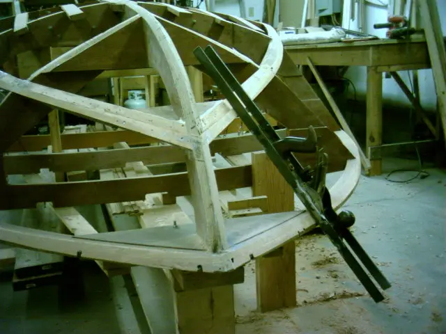
Sheer fairing nearing completion. To span from chine to sheer, we've welded two 30" long pieces of 1/8" by 1" flat steel bar to each side of an old jack plane. This speeds up the fairing process and is very accurate.
Chine was faired from frame # 4 to the stem.
3 Apr 2006Fairing & Sanding
Most of the first sheer lamination was faired away
Most of the first sheer lamination was faired away.
5 Apr 2006Hull Panels
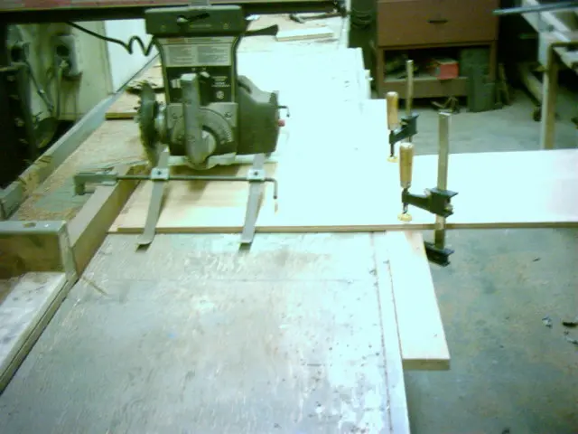
Since the Bill Of Materials call for a single layer of 1/4" sheeting for the sides, we'll be using 1/4" 5-Ply Meranti ma
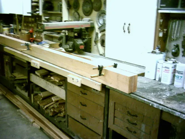
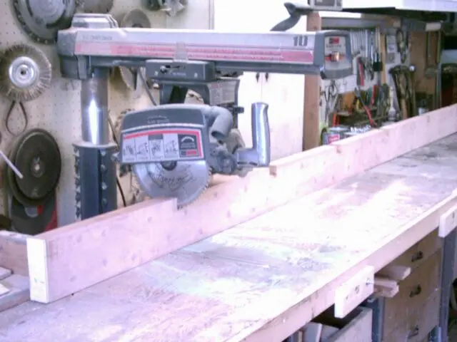
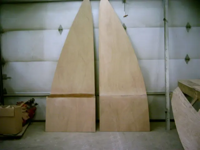
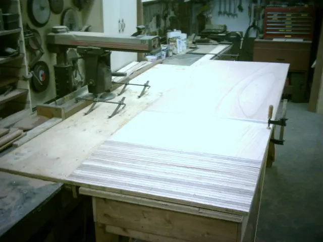
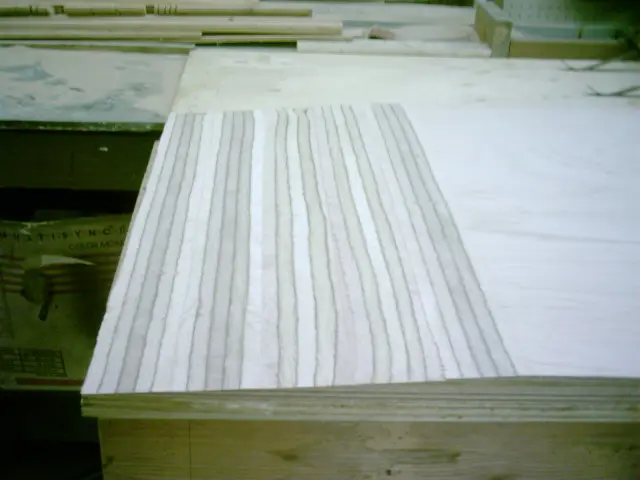
Since the Bill Of Materials call for a single layer of 1/4" sheeting for the sides, we'll be using 1/4" 5-Ply Meranti marine grade plywood. Five sheets were ripped into 31" wide strips and scarfed on the radial arm saw. Click here to see how the saw was set up to make the cut.
Scarfed sheeting was stacked and will be finished with an air file. This will roughen up the joint and provide a better bonding surface for the epoxy.
10 Apr 2006Hull Panels
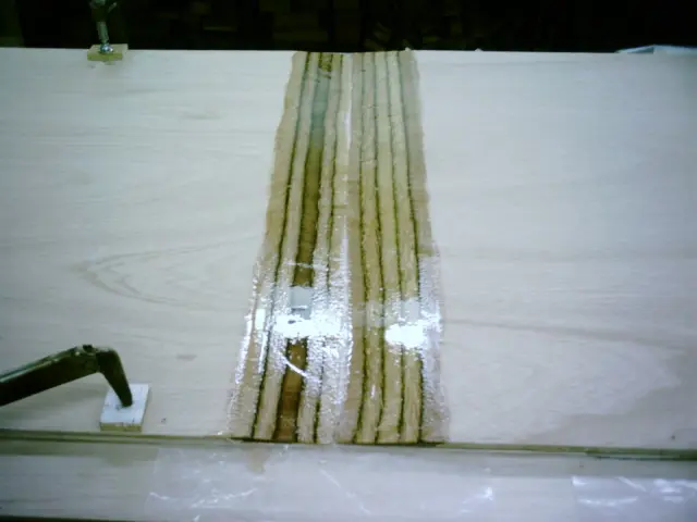
Here's a shot of the last side planking scarf joint being epoxied
Here's a shot of the last side planking scarf joint being epoxied.
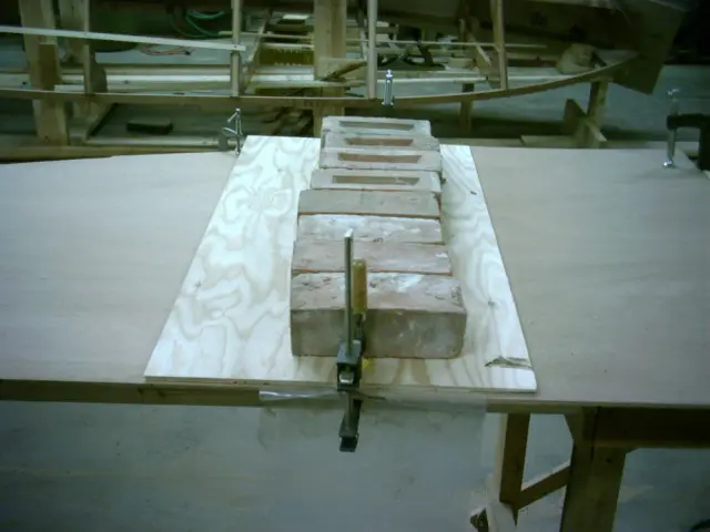
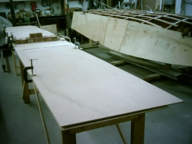
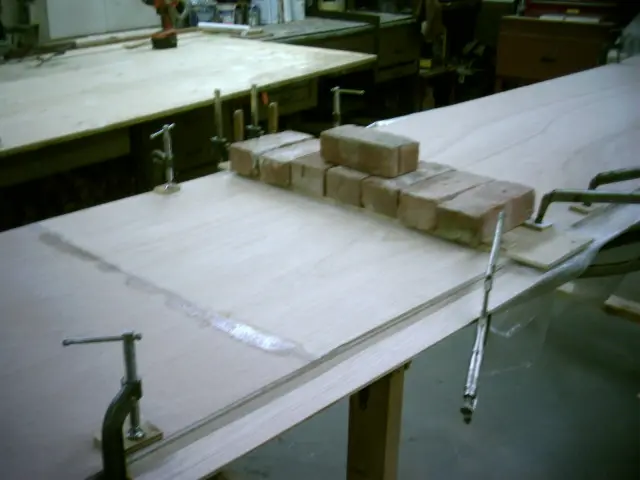
Several bricks are used to clamp the joint. Excessive weight will squeeze too much epoxy from the joint and lead to an unsound joint. In the background, we're fitting the douglas fir side planking template to the side of the boat.
18 Apr 2006Fairing & Sanding
The frame sides must be faired so that they don't project against the plywood planking
The frame sides must be faired so that they don't project against the plywood planking. This would cause a 'hard spot' which could cause the panel to fracture. Our trusty router jig was clamped to the side of the frame.
The router bit depth was set to cut 1/16" below the chine surface.
The operation was repeated at the sheer junction. A block plane was used to fair the remainder of the frame.
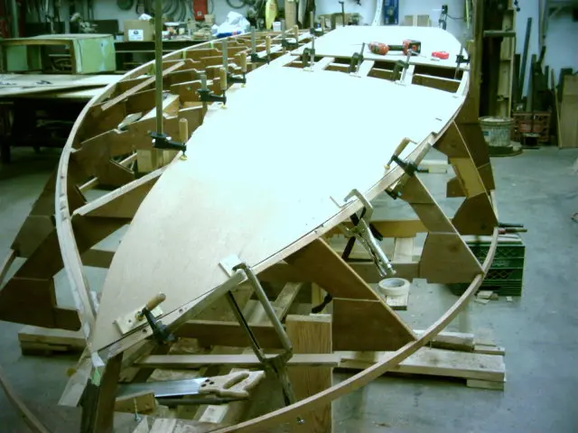
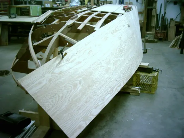
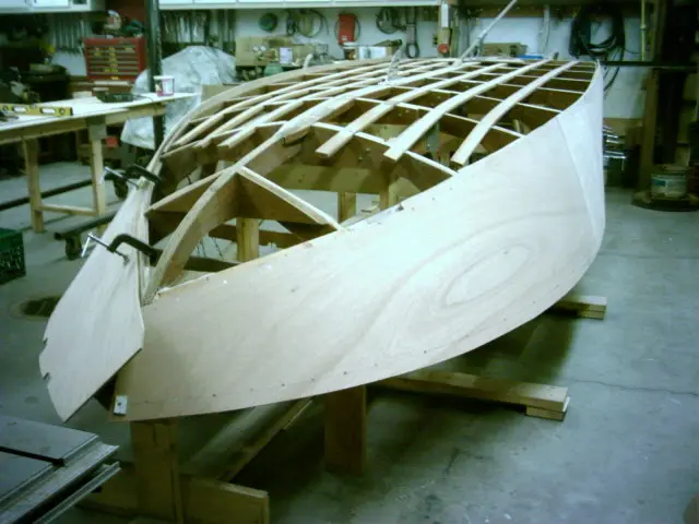
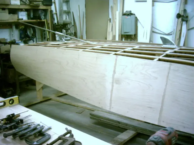
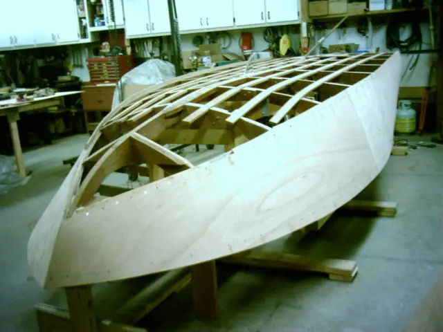
Starboard side planking installed. The port side is being fitted.
Two scarf joints fall between frames #4 and #6.
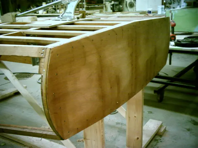
View from the starboard rear. The tumblehome is quite severe but the 5 ply marine plywood conforms to the radius quite easily.
11 May 2006Hull Panels
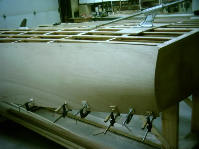
Side planking was fastened with 1" #8 screws spaced 3" apart at the chine and 4" apart at the sheer
Side planking was fastened with 1" #8 screws spaced 3" apart at the chine and 4" apart at the sheer.
Screws will be spaced 2" apart at the stem and transom.
15 May 2006
Drainage limbers were cut into the rear battens
Drainage limbers were cut into the rear battens. Router depth was set at 3/8".
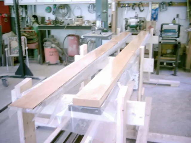
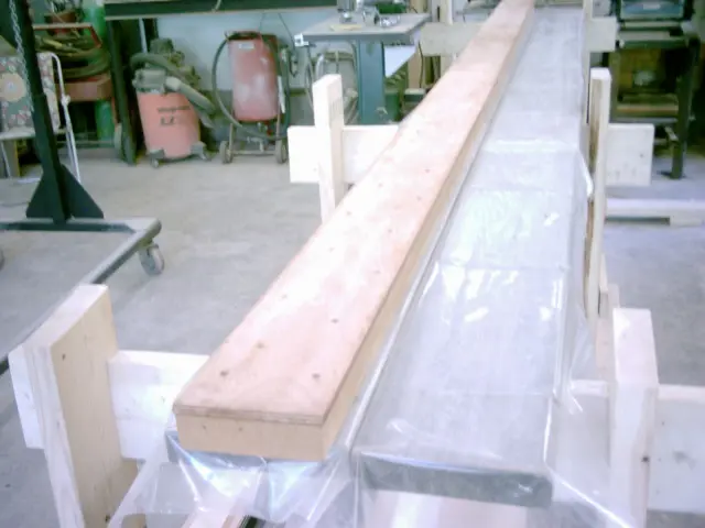
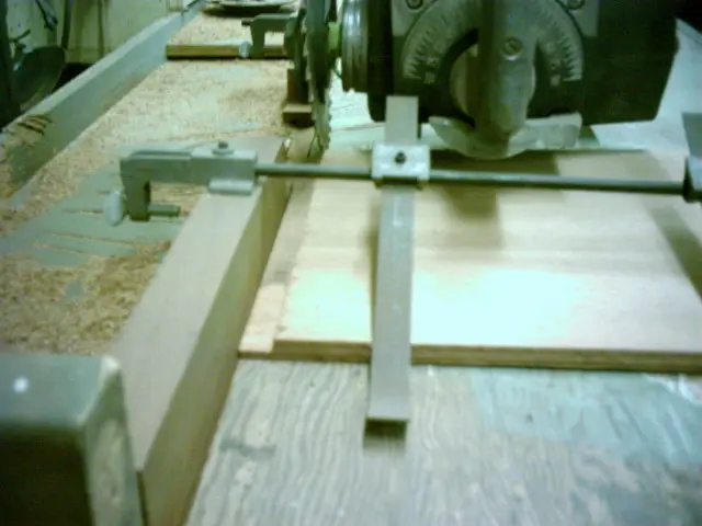
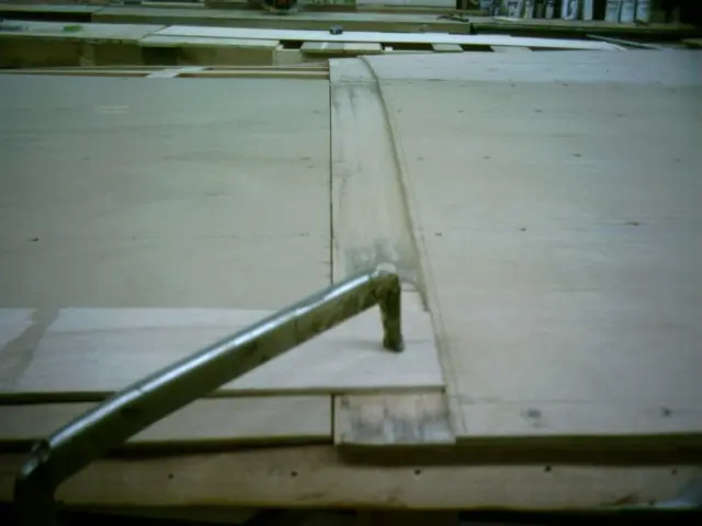
Setting up the radial arm saw to cut a 3" wide by 1/4" deep rabbet on the leading edge of the 1/2" bottom plywood. A 'wobble' dado blade set at 11/16" wide speeds up the process. A 1" x 2" guide batten is clamped to the stock and runs along the saw table apron.
Closeup view of the rabbet.
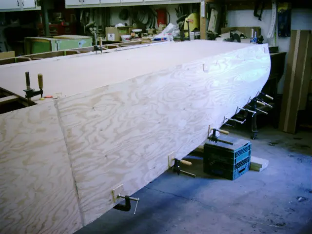
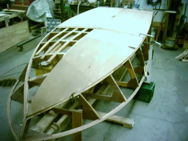
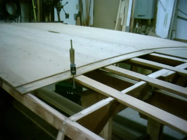
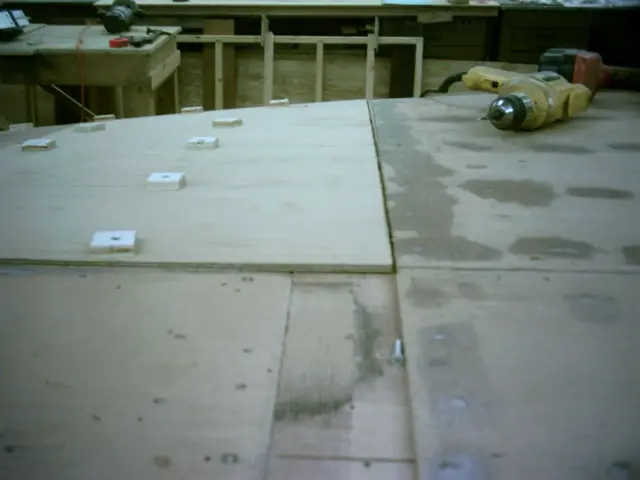
Both 1/2" panels installed.
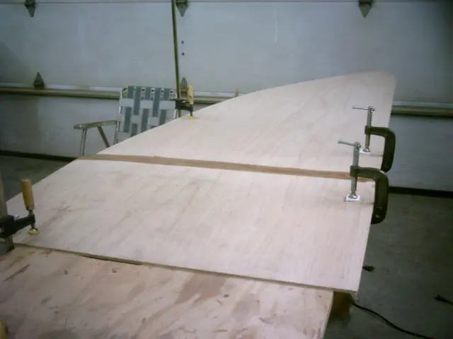
The first 1/4" front panel butts to the rear ply. The second 1/4" panel overlaps the rear ply by 3".
1/2" plywood butt blocks will be fitted between the limbers. A jigsaw was used to trim around the shaft hole. A 1-3/4" diameter hole saw makes quick work of cutting the rudder port hole.
19 May 2006
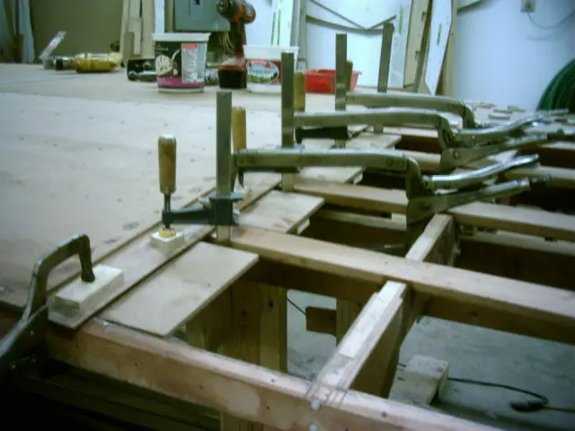
Butt blocks epoxied and clamped
Butt blocks epoxied and clamped.
To enhance drainage, we've left a 3/4" wide limber between the butt block and batten.
20 May 2006
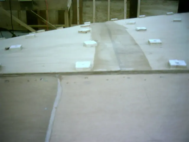
Plywood washers were used to increase the screw's clamping pressure
Plywood washers were used to increase the screw's clamping pressure. The mating surfaces were checked for gaps from inside the boat.
Shorter screws were driven into the butt blocks.
22 May 2006Strongback & Molds
Prior to panel removal, keel, chine, batten, and butt block locations were traced with a pencil from inside the boat
Prior to panel removal, keel, chine, batten, and butt block locations were traced with a pencil from inside the boat. Areas not to be covered with epoxy were taped off. The taping is extra work but saves a lot of cleanup time ! Epoxy was applied to both mating surfaces and allowed to set for several minutes. West System 403 adhesive filler was added to the catalyzed epoxy and spread over the mating surfaces. To aid fastener removal from the panel once the epoxy cures, strips of plastic film were slid under the plywood washers.
27 May 2006Hull Panels
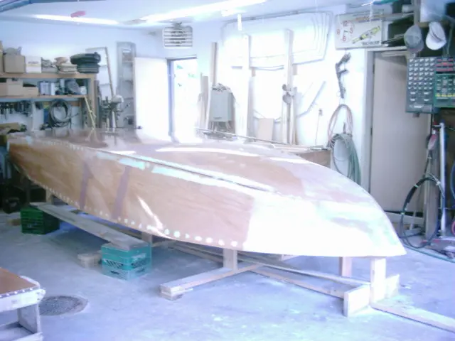
Second bottom panels (1/4" marine grade plywood) were cut, scarfed and epoxied
Second bottom panels (1/4" marine grade plywood) were cut, scarfed and epoxied. Joint was set 6" aft of the first bottom's joint.
28 May 2006
Port side first bottom ready to be epoxied
Port side first bottom ready to be epoxied.
3 Jun 2006
Port first bottom
Port first bottom.
5 Jun 2006
Starboard side
Starboard side.
6 Jun 2006
Port side
Port side.
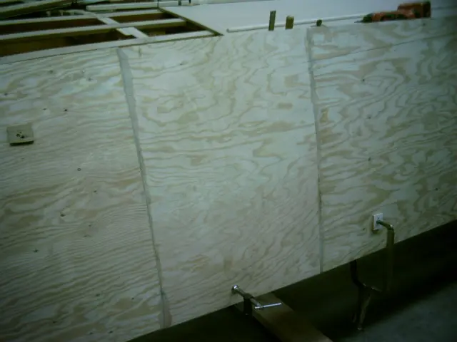
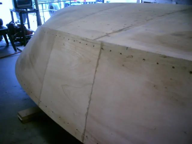
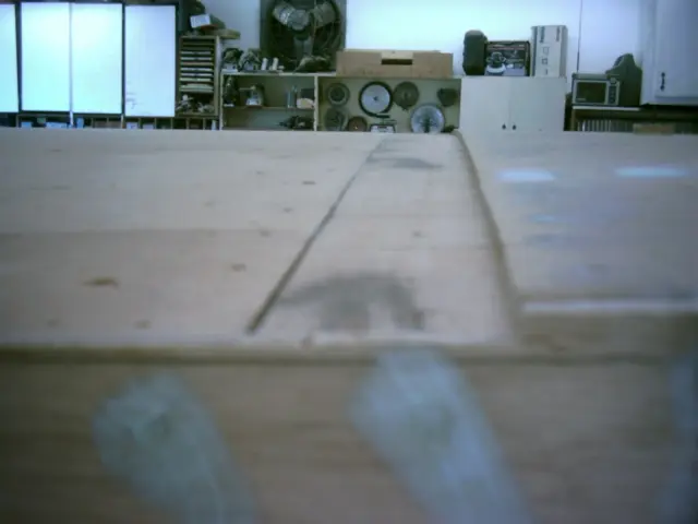
Panels are butted in forward section, lapped in aft.
Transition point.
Butt joint detail.
7 Jun 2006Hull Panels
Fitting the port second bottom
Fitting the port second bottom.
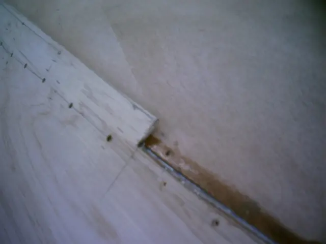
Transition point.
Butt joint detail.
The second bottom's scarf joint is staggered 6" aft of the first bottom's joint.
8 Jun 2006Hull Panels
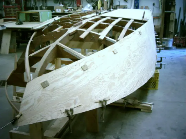
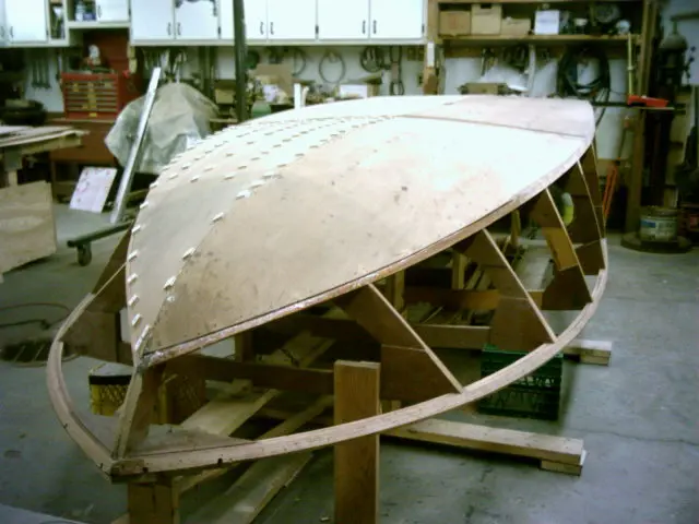
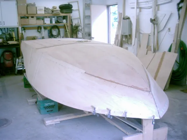
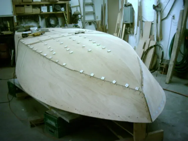
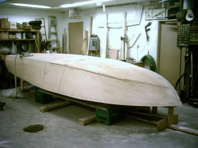
Both second bottom panels installed
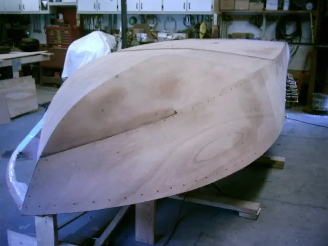
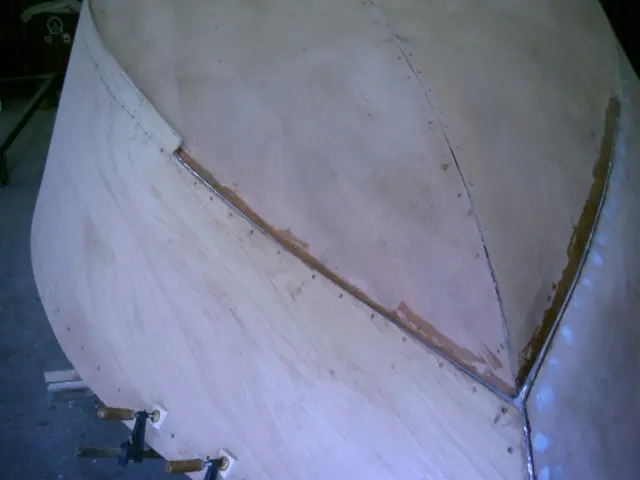
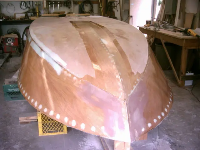
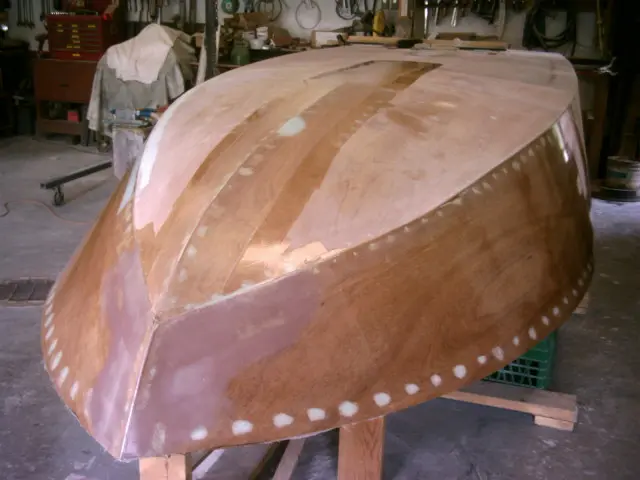
Both second bottom panels installed.
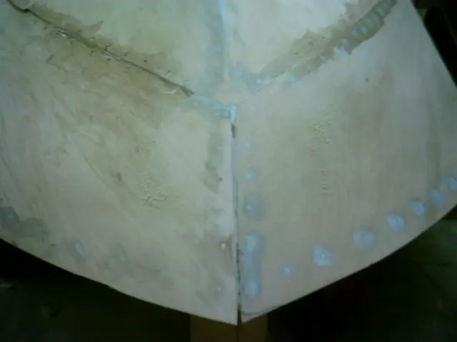
Bow detail.
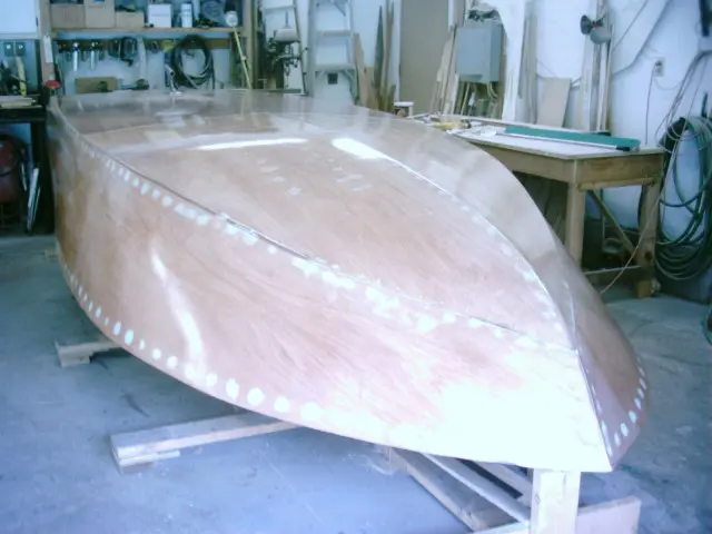
10 Jun 2006Fairing & Sanding
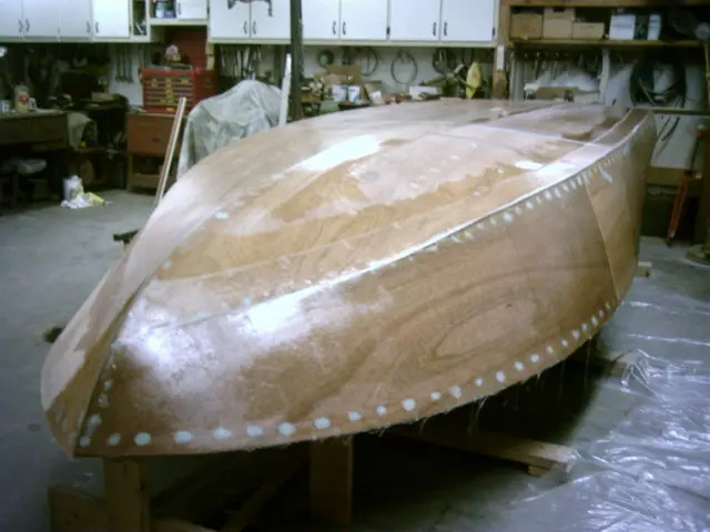
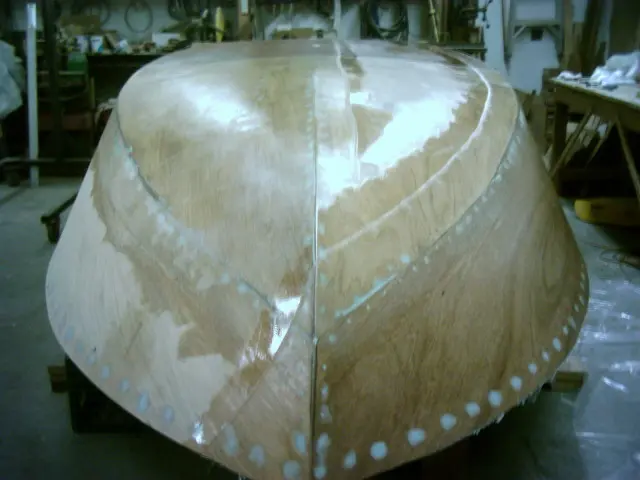
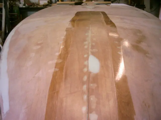
Screw holes were puttied with Interlux Watertite YAV135
Screw holes were puttied with Interlux Watertite YAV135. It's a two-part, fast drying epoxy compound for filling holes, repairing scratches in gelcoat and fairing fiberglass. It can also be used below the waterline to fill gelcoat blisters.
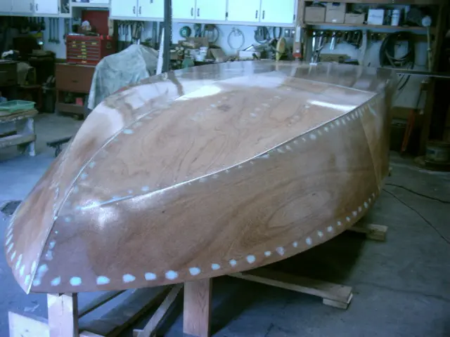
18 Jun 2006Glassing & Epoxy
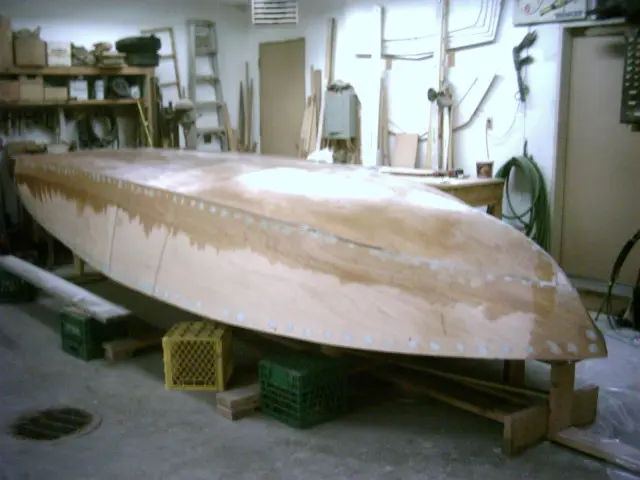
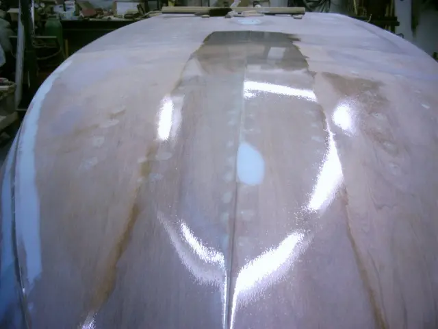
On Friday night we fiberglassed the starboard bottom
On Friday night we fiberglassed the starboard bottom. We feathered the panel edges on Saturday afternoon and applied the port bottom late Saturday night. Starboard side was applied late Sunday night.
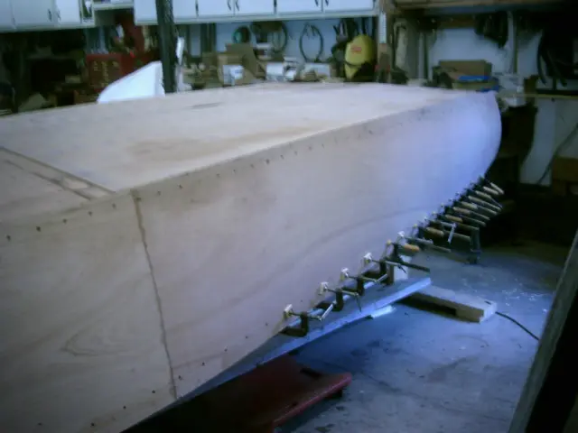
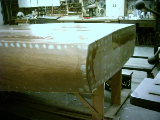
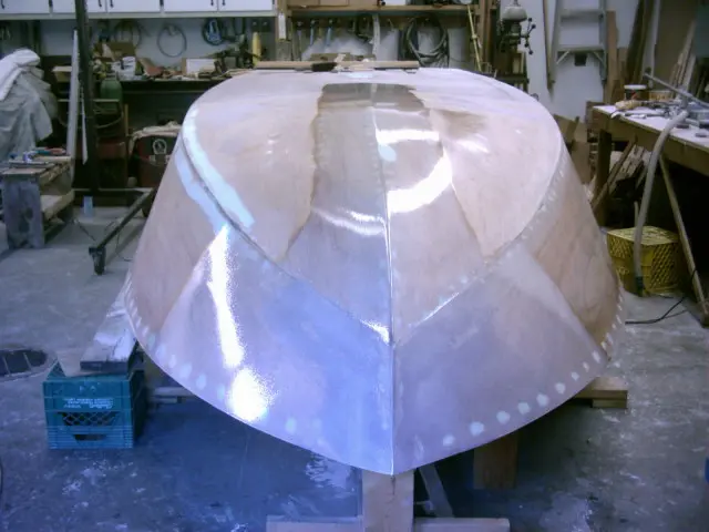
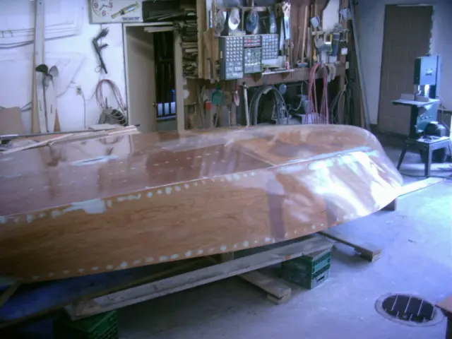
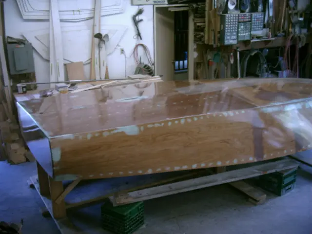
Notice the starboard side overlap at the bow. The digital camera is having a rough time rendering smooth, shiny surfaces. Time to upgrade to a better quality unit !!
Side overlaps the transom.
Port bottom will have to be feathered before applying the side.
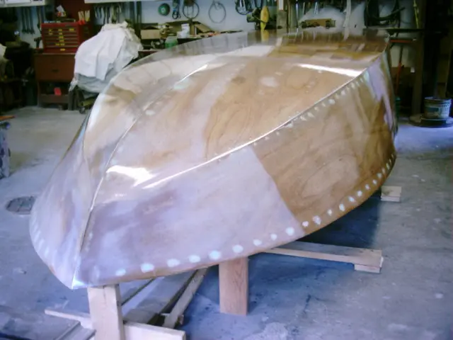
19 Jun 2006Glassing & Epoxy
We're applying the fiberglass cloth using the 'dry method'
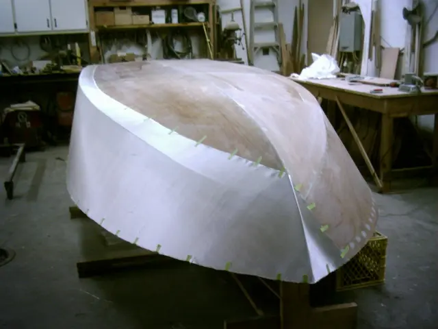
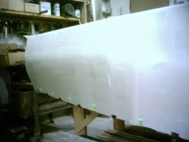
We're applying the fiberglass cloth using the 'dry method'. 6.5 oz. cloth is draped over the hull and taped in position. Panel overlap is 5". This allows for sufficient overlap and a 1-1/2" wide strip for feathering.
Stretching the cloth diagonally eliminates wrinkles. Spring steel paper clamps and masking tape are removed after the cloth has been saturated with epoxy.
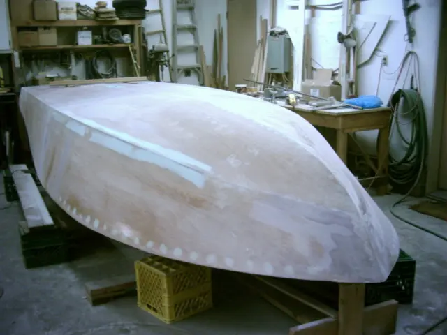
25 Jun 2006Fairing & Sanding
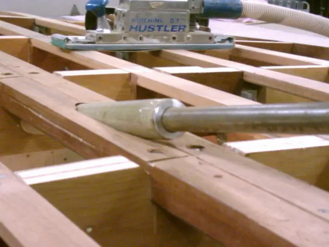
Took Friday off to feather the overlaps and sand the hull with 40 grit sandpaper
Took Friday off to feather the overlaps and sand the hull with 40 grit sandpaper. Straight-line and orbital air files saved a lot of time on this job. We splurged on a DeWalt commercial duty 6" variable speed orbital sander for feathering the overlaps. The hull was rinsed with water, scuffed with a 3M scotch pad and allowed to dry overnight. Three rounds of epoxy spaced about two hours apart were applied on Saturday.
Filling and fairing is next !
1 Jul 2006Glassing & Epoxy
Over the long weekend, we laminated three strips of fiberglass cloth on the chine and transom edges and ground them to a
Over the long weekend, we laminated three strips of fiberglass cloth on the chine and transom edges and ground them to a crisp profile.
7 Jul 2006Fairing & Sanding
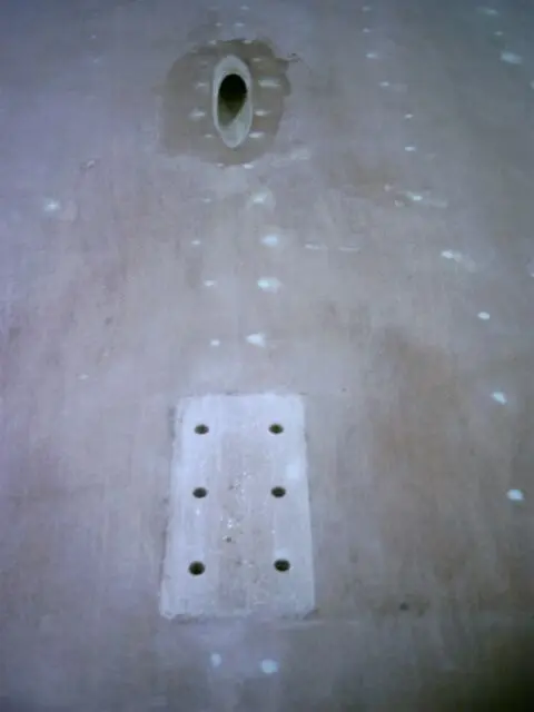
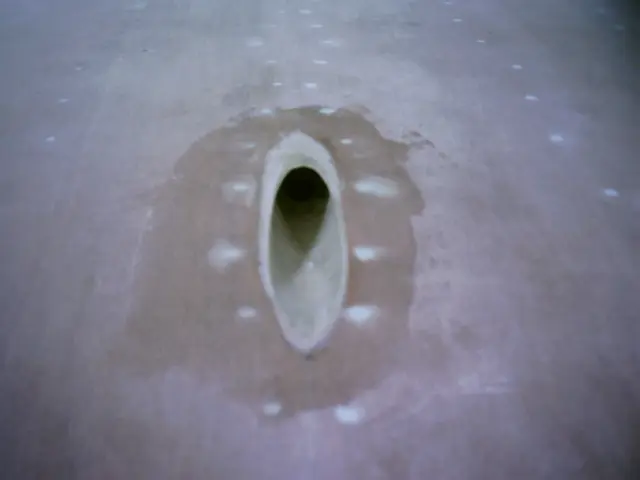
A strut pad was laminated from 3 layers of 1-1/2 ounce fiberglass mat
A strut pad was laminated from 3 layers of 1-1/2 ounce fiberglass mat. The idea is to build up the pad and grind it level so the strut can be bolted to a solid base.
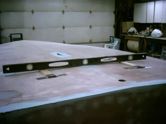
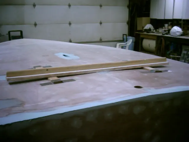
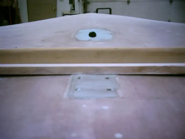
A 4-foot level was laid on the pad and leveled with two hardwood strips laid on the hull. Duck tape was used to hold the strips in place.
A 4-foot long sanding board was used to level the pad.
Detail shot.
8 Jul 2006Systems
The shaft tube was epoxied and trimmed
The shaft tube was epoxied and trimmed. Click here to review how the strut and tube were fitted when the keel was installed.
View from inside the hull. The plan is to fiberglass the keel before installing the shaft log.
Strut and shaft installed.
Viewed from the top.
17 Jul 2006Fairing & Sanding
An extra layer of cloth was applied to the keel and the bow area
An extra layer of cloth was applied to the keel and the bow area. If the keel is nicked or abraded, the extra lamination will take the abuse instead of the underlying layer.
Since this is a 'wear' layer, sanding will be restricted to feathering the sides.
A test batch of white pigmented epoxy was mixed and applied. It would take quite a bit of pigment or several coats of epoxy to produce a truly opaque finish.
21 Jul 2006Glassing & Epoxy
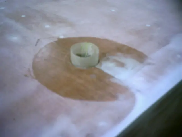
We epoxied a fiberglass rudder port tube into the rudder port hole
We epoxied a fiberglass rudder port tube into the rudder port hole. It's a little more work, but if the rudder port sealant fails, water will not be in direct contact with the keel.
22 Jul 2006Paint & Finish
We applied the last three epoxy barrier coats on Saturday
We applied the last three epoxy barrier coats on Saturday.
The first two coats were catalyzed with West System 206 Slow Hardener. Each coat was tipped off with a squeegee made from a 7" foam roller cover split lengthwise. Instructions on how to make the tool are printed on the West System roller cover packaging. The epoxy was allowed to cure for three hours before recoating.
The last coat was catalyzed with West System 207 Special Coating. Normally used in clearcoat applications, it flows out better than the 206 hardener since it's mixed at a 3:1 ratio instead of the usual 5:1 ratio for 205 and 206 hardeners.
The 207 flowcoat should reduce the final sanding to a minimum. Once fully cured, the hull will be sanded with 40 grit sandpaper to prepare it for primer.
29 Jul 2006Paint & Finish
On Friday night, the hull was washed with water and scuffed with a Scotch pad to remove sanding sludge
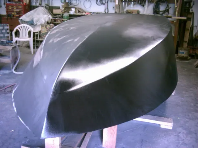
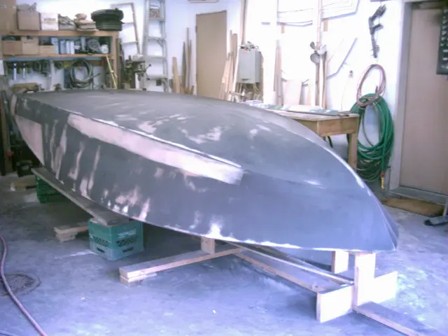
On Friday night, the hull was washed with water and scuffed with a Scotch pad to remove sanding sludge. On Saturday morning, the hull was cleaned with DuPont Plas-Stick Plastic-Prep 2319S. It's a ready-to-use unprimed plastic parts cleanner designed to remove mold release agents and other surface contaminants and eliminate static. Click here for a product usage guide. The substrate was wiped with a 2K tack rag (made for plastics and urethane finishes) before applying the primer. A medium wet coat of Polyval Polyur 559 Black Epoxy Primer was applied with an HVLP spray gun. This industrial 2 component coating is rated for immersion service (very rare for primers) and is available in red, gray, white, yellow and black. We chose the black because it highlights surface imperfections better than the other colors. After curing for 4 hours, we blocked out the hull with 100 grit sandpaper on a 24" flexible sanding board. The primer did a great job of filling most of the 40 grit sanding marks left from the initial sanding. Low spots (mainly along the chine at the fiberglass overlap) were filled with System Three QuikFair epoxy filler. Other lighter-colored spots are sanding break-throughs or high spots. Two rounds of DuPont 4007S 2K Ultra Productive Primer-Filler were applied to the hull and block-sanded with 100 and 180 grit sandpaper. This was followed up with a coat of DuPont ChromaPremier Sealer which was then sanded with 240 grit sandpaper. (14-AUG-2006 - 17-AUG-2006)
18 Aug 2006Paint & Finish
The shop was cleaned up, the painting tarps were hung on the walls and furnace filters were slipped into the rear screen
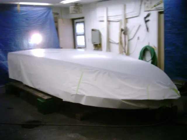
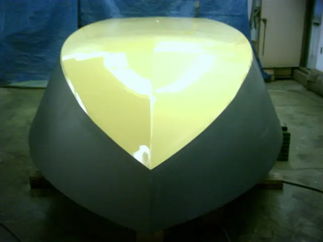
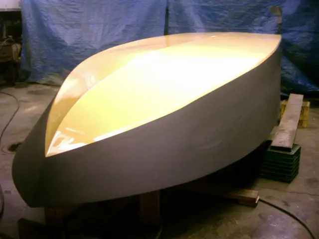
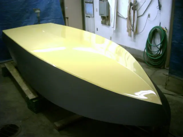
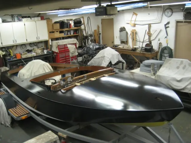
The shop was cleaned up, the painting tarps were hung on the walls and furnace filters were slipped into the rear screen door. The hull was washed with plain water, dried with Torx wipers, prepped with Plastic-Prep and tacked with a 2K tack rag. A medium coat of DuPont ChromaBase Basecoat (white) was applied and allowed to flash for 15 minutes. If this was an ordinary boat, we'd clearcoat the white and we'd be done. Since this is a Hot Rod, it's gotta look hot !!
We'd normally use DuPont Imron as our topcoat, but the pigment required to mix the Corvette Yellow was no longer available. Switching to PPG solved the problem. Three coats of PPG finish off the job. This is a single stage, two-component acrylic urethane topcoat which should provide maximum scuff resistance.
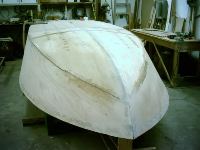
The hull was left to cure for 4 days after painting.
Chapter 07
Trailer & Gear
Trailer build or rework, cradles, covers, launching gear.
4 daysfrom August 2006
23 Aug 2006Trailer & Gear
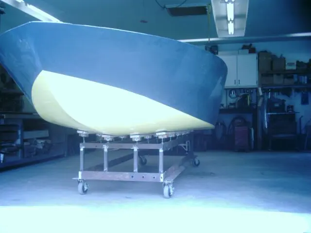
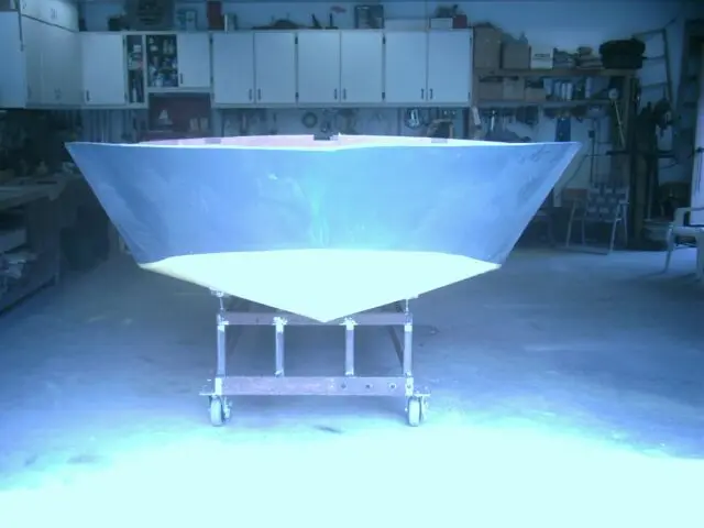
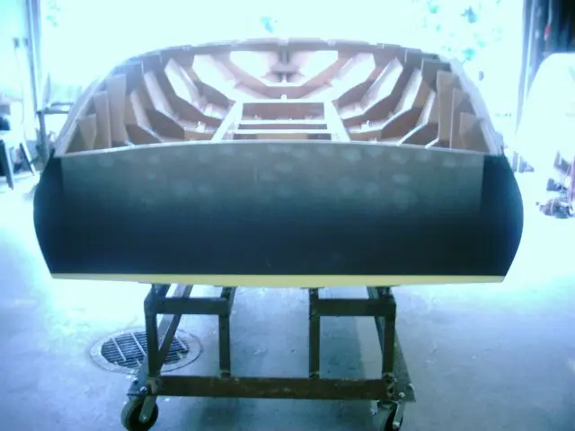
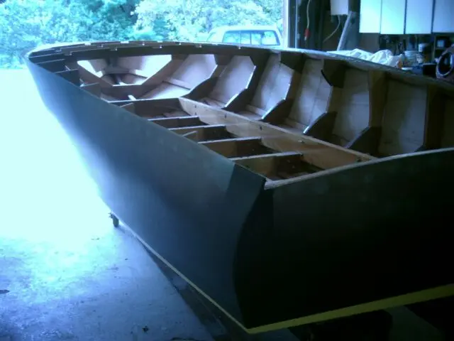
A heavy-duty mobile dolly was fabricated for the hull
A heavy-duty mobile dolly was fabricated for the hull. Four 10' lengths of 3" C-Channel spaced 12 incches apart provide ample support. Righting the hull was accomplished with minimal fuss. Seven friends showed up for the roll. The hull is so light they lifted it off the setup jig, rotated it and placed it onto the dolly without even resting the sheer on the ground. Many thanks to Jack, Dave, Big John, Brian and the Chelsea lads.
We fabricated adjustable bunks similar to the ones used in the trailer.
The dolly is quite narrow. We can still access the sides and bottom which wouldn't be the case if the boat was simply loaded on the boat trailer.
The horizontal crossmember was cut to allow installation of the rudder, strut and propeller shaft.
The plan is to barrier-coat the interior with two coats of epoxy and apply a two-component urethane clear topcoat.
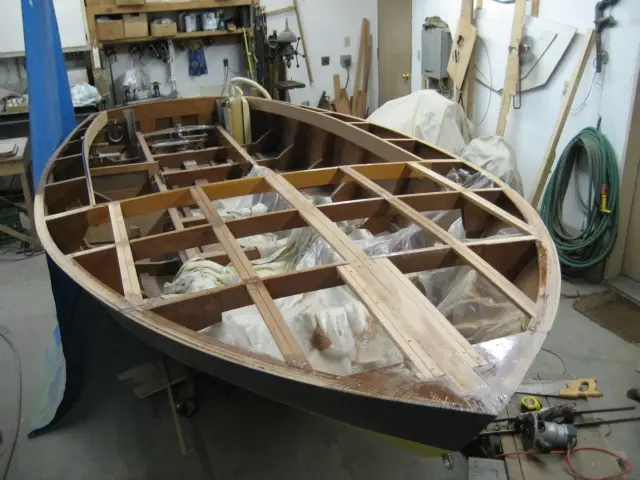
A temporary dash and a Teleflex NFB Dual Cable helm were installed. A 20' cable was fed into the helm and laid out to measure the length of cable required. Also visible are the driver's seat track and the 2 gas tank enclosure panels (between frames # 3 and 4).
Frame # 4 has to be cut to make room for the stuffing box.
A 3/4" strip is left on either side of the keel. A frame brace will have to be fabricated to reinforce the frame.
26 Oct 2006Systems
Photo quality should improve drastically from this point on
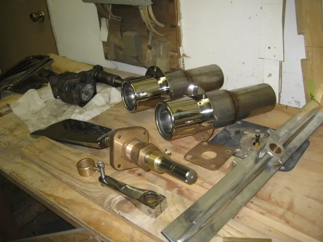
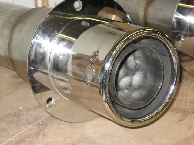
Photo quality should improve drastically from this point on. We bought a new Canon PowerShot SD600 digital camera. Hopefully the closeup and white color balance issues I had with the old camera are a thing of the past ! The rudder and rudder support bracket are back from the machine shop. 3-1/2" stainless steel pipe stubs were tig-welded to the Gibson Transom Mount mufflers. We also picked up a 1350 series Center H Yoke which will replace the torque tube.
These performance mufflers should be legal at idle. Can't wait to hear them when that 283 comes to life !
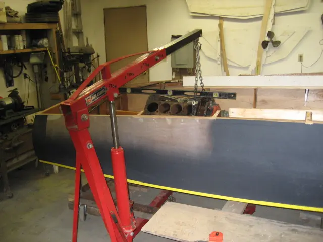
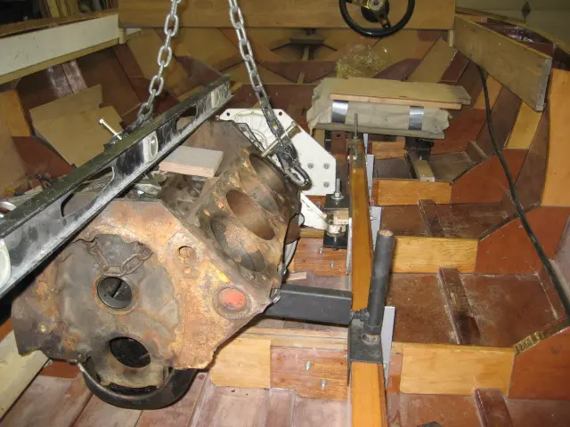
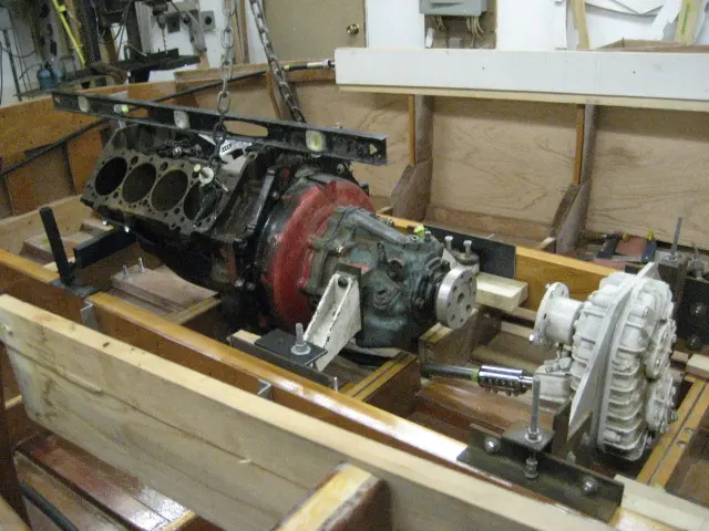
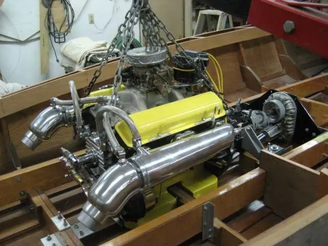
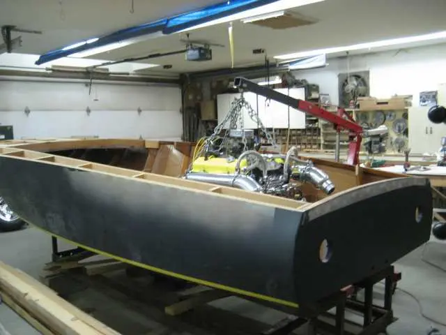
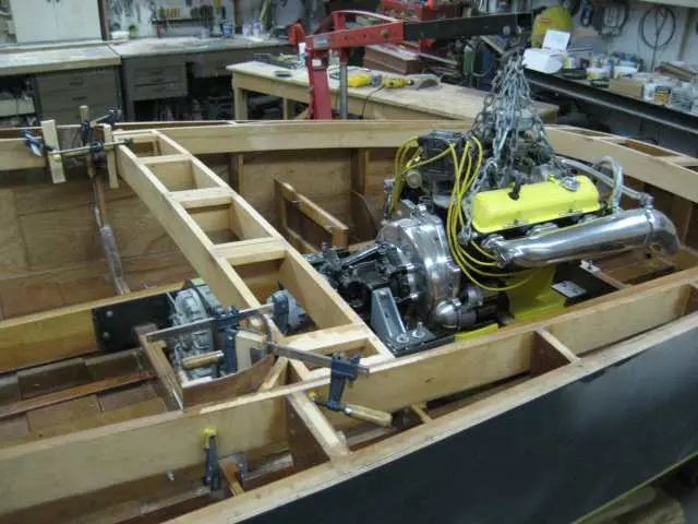
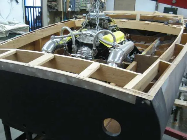
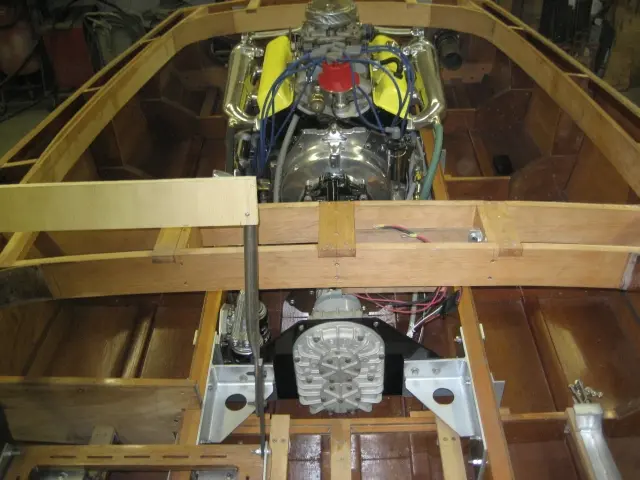
A bare-block 400 cubic inch V8 was bolted to the Velvet Drive transmission and hoisted into position.
Temporary motor mounts provide up, down and side-to-side adjustment.
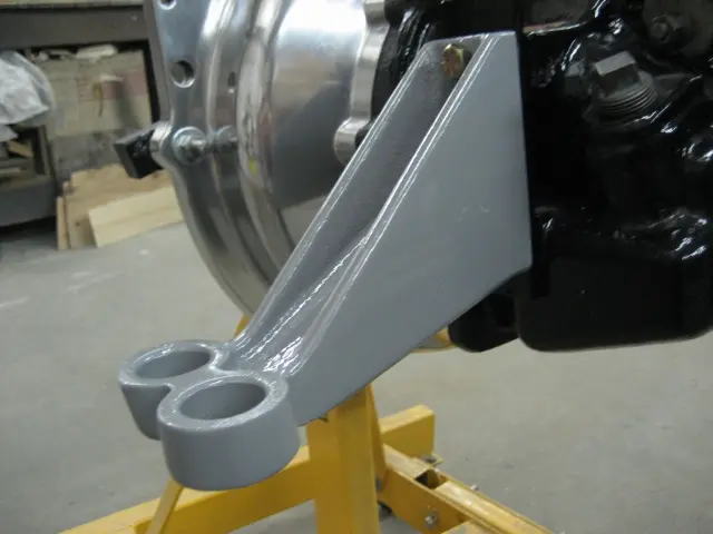
Found some vintage transmission mounts at Ayling's Boat Yard. They're stout pieces and fit better than the previous ones I had. A new set of stringer brackets is being fitted.
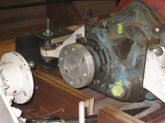
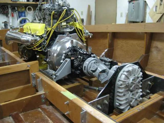
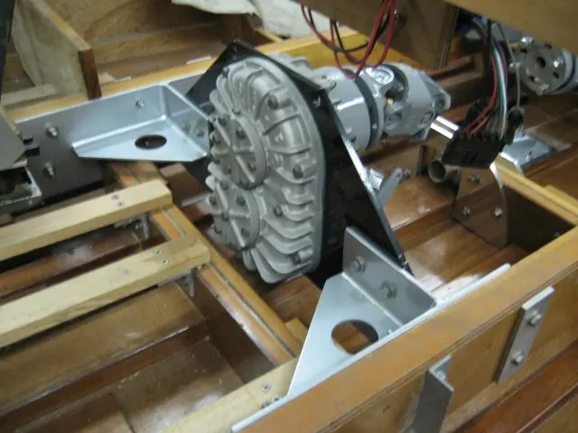
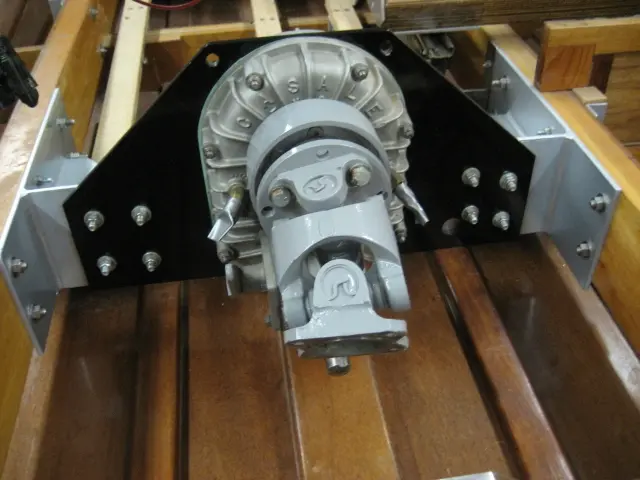
A 1350 series Borg Warner power takeoff (Glenwood Part # 90-797) is bolted to the Velvet Drive transmission's output shaft. Ratio is 1:1. The used Casale 12 degree v-drive with 15% overdrive was equipped with a 1350 series V-drive flange takeoff (Glenwood Part # 90-865).
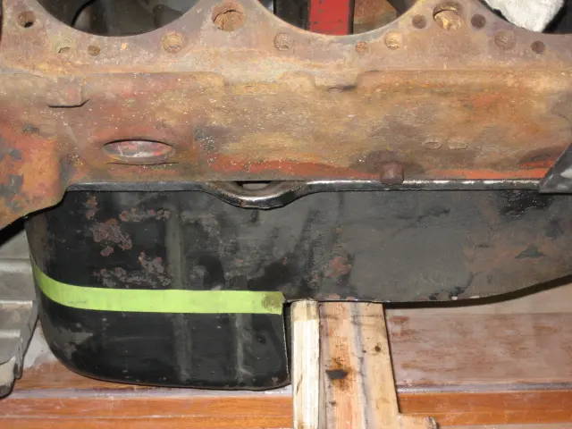
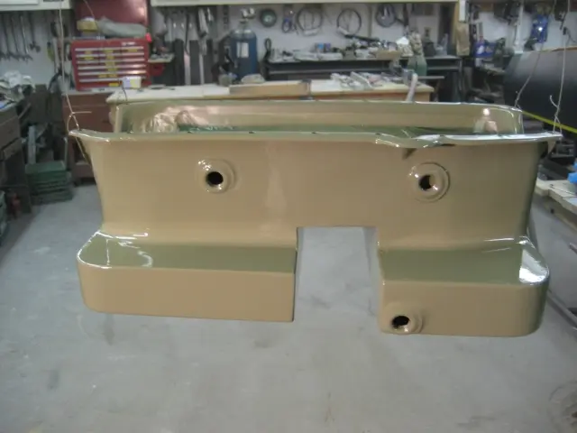
Cutting into the oil pan (adjacent to the frame) moves the engine back far enough to install a 6-1/2" long H joint instead of the 10-1/2" long torque tube (Glenwood Part # 90-835) we initially thought would be used. This also drops the engine down 2" closer to the keel. To provide more oil capacity, a front sump and kicked-out sides will be added to the pan.
30 Oct 2006Systems
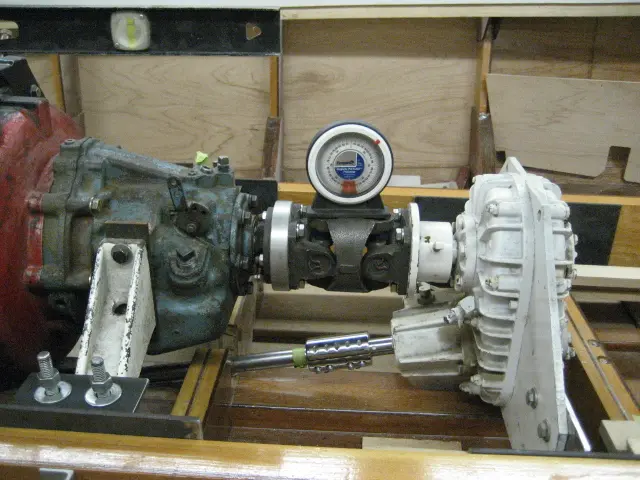
The H joint was bolted up to the transmission flange
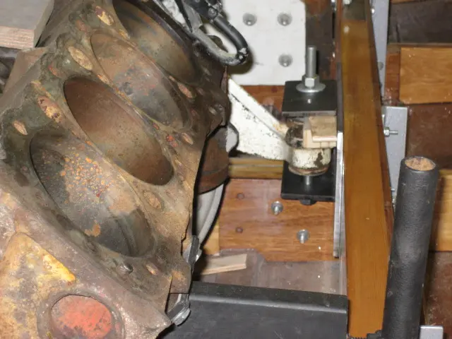
The H joint was bolted up to the transmission flange. The v-drive was pushed back and down until the propeller shaft coupler rotated freely on the propeller shaft.
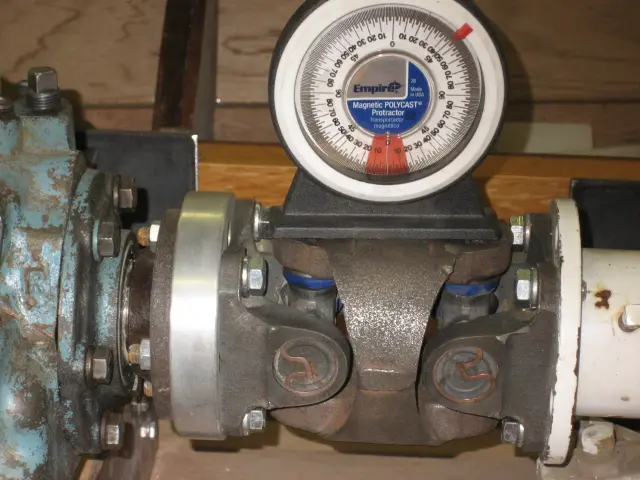
An inclinometer (angle finder) was used to set the H joint at 0 degrees. The v-drive mounts can be now be welded in their final location.
8 Nov 2006Systems
The oil pan sump was cut to move the engine 1-1/2" aft and 2-1/2" lower
The oil pan sump was cut to move the engine 1-1/2" aft and 2-1/2" lower. This will obviously generate quite a bit of work... A simpler solution would have been to either install the frame timber on the aft side of the frame or move the entire frame 2" aft. If the latter is done, the frame outline would change (frame would not be as wide) so you'd have to loft frames #0 through #5 to pick up the new chine and sheer points.
Chapter 08
Brightwork & Varnish
Trim, coamings, varnish schedule, oiled finishes.
1 dayfrom December 2006
18 Dec 2006Brightwork & Varnish
Work on barrier coating the interior of the hull continues
Work on barrier coating the interior of the hull continues. We're going with a bright finish consisting of two rounds of West Epoxy catalyzed with 207 Special hardener. This will be followed with two or three rounds of two-part urethane clear.
The second coat of epoxy is still a little rough. Epoxy is not self-levelling like paint. Visible in this photo are the side panel scarf joint and the bottom panel butt blocks. Switching to a spray gun for the subsequent varnish coats will minimize sanding between coats and flatten out the surface !
Chapter 09
Deck & Coamings
Decking, hatches, coamings, cockpit rim.
3 daysfrom February 2007
3 Feb 2007Deck & Coamings
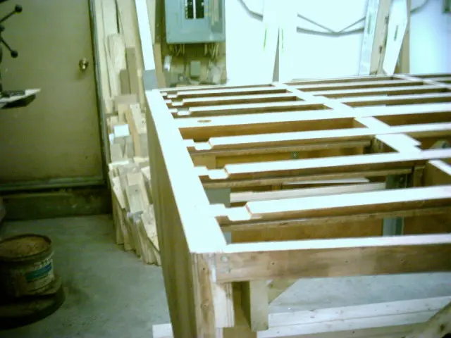
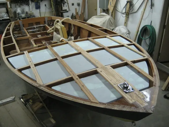
We're currently fabricating removable foam flotation panels which will be installed under the deck battens
We're currently fabricating removable foam flotation panels which will be installed under the deck battens. Click here to see what we've done so far. ( a new window will be opened)
20 Mar 2007
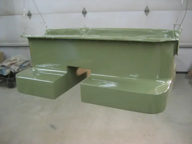
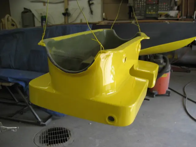
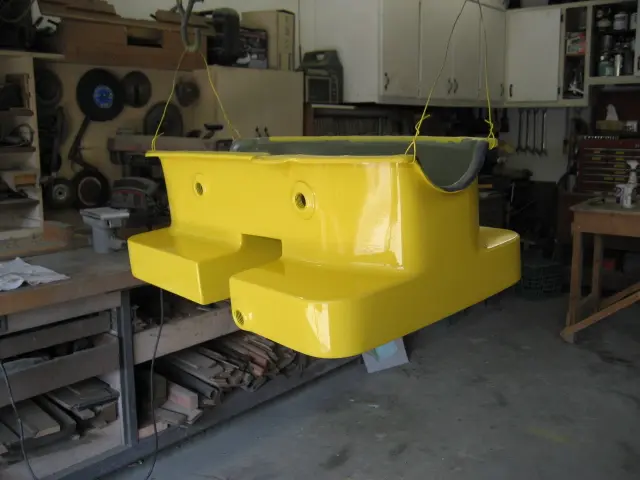
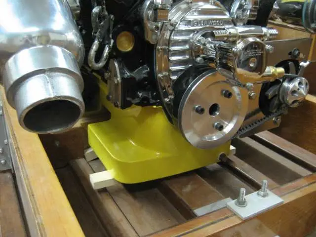
We've added kickouts to the rear sump and added a new sump at the front
We've added kickouts to the rear sump and added a new sump at the front. Click here to see how the pan was fabricated. ( a new window will be opened)
The ledge around the bottom of the sump should inhibit oil movement. We want to ensure that the oil pickup doesn't run out of oil when the bow rises while accelerating.
20 Mar 2007Fairing & Sanding
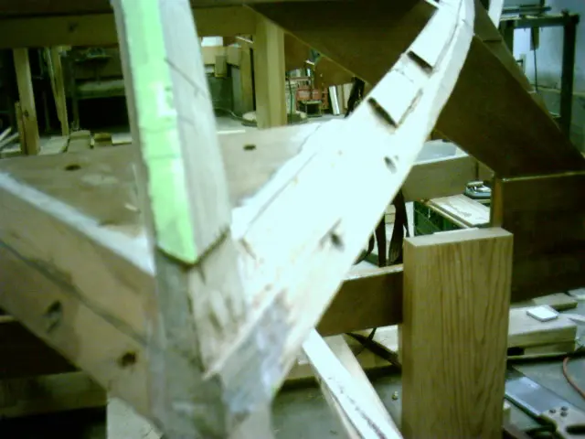
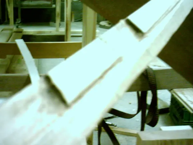
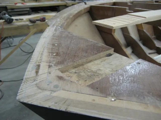
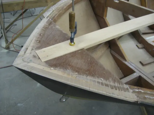
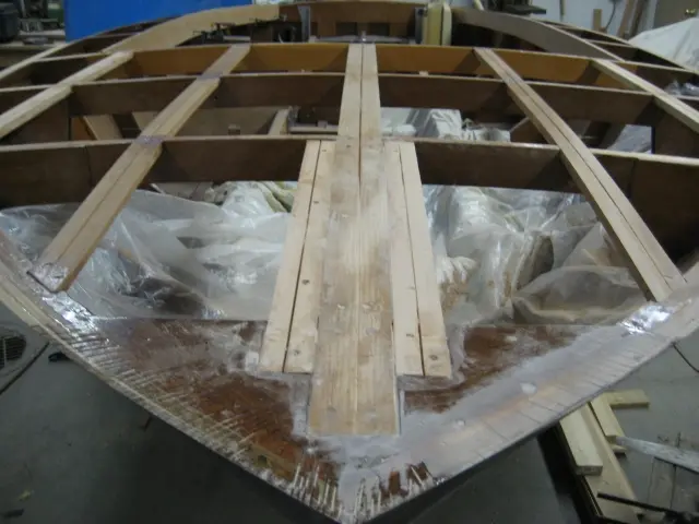
The breasthook was notched to a depth of 3/8"
The breasthook was notched to a depth of 3/8". The strongback was taper-notched from 3/8" at the leading edge to 1/8" at rear.
The tip of the strongback is flush with the breasthook's leading edge.
The sheer can now be faired.
5 Apr 2007Paint & Finish
While we're waiting for the last wood order to arrive (Douglas Fir for the carlings and intermediate deck beams), we pre
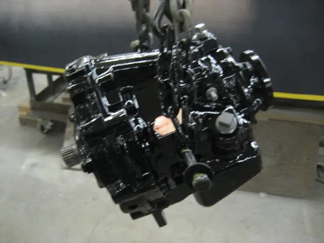
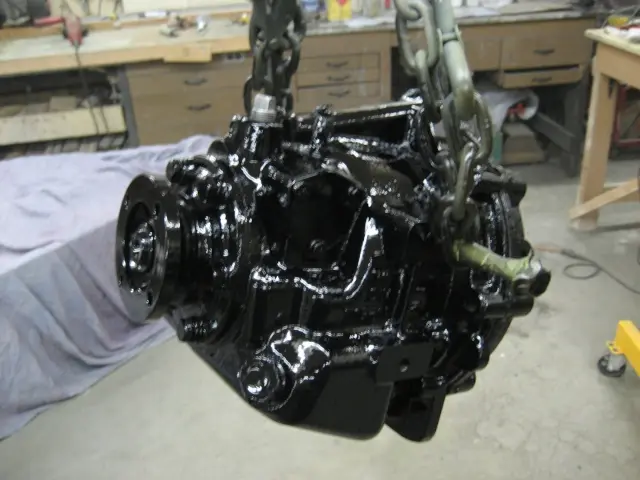
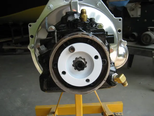
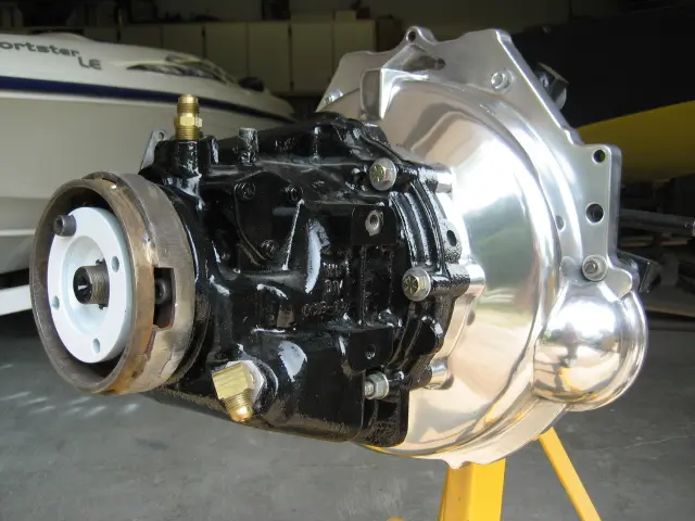
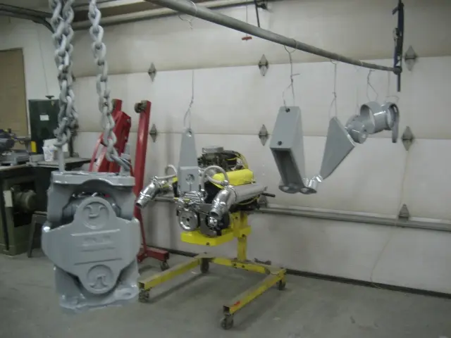
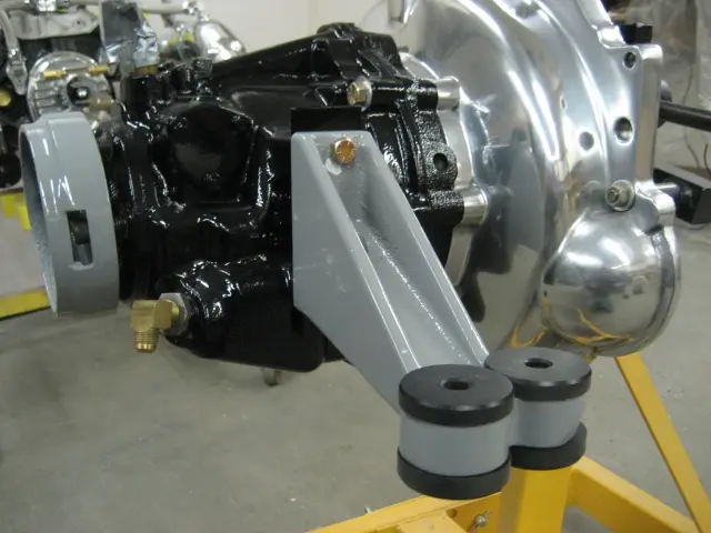
While we're waiting for the last wood order to arrive (Douglas Fir for the carlings and intermediate deck beams), we prepped and painted the Velvet Drive transmission.
The transmission was stripped of old paint, sanded to bare metal, metal conditionned, degreased with DuPont Wash & Wipe, primed with DuPont DTM Urethane Primer and topcoated with Dupont Imron urethane.
7 May 2007Paint & Finish
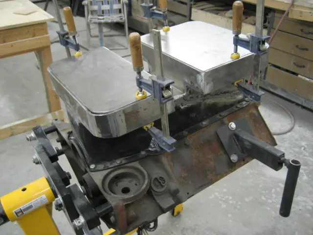
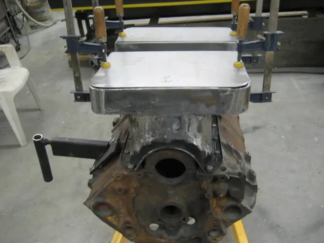
Welded joints were silver-soldered and the oil pan was tested for leaks
Welded joints were silver-soldered and the oil pan was tested for leaks. Several rounds of aluminized body filler (Evercoat Metal-2-Metal) were applied and smoothed out. The pan was prepped and shot with two coats of DuPont 2580CR DTM primer.
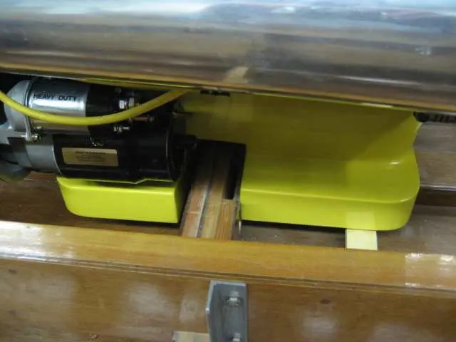
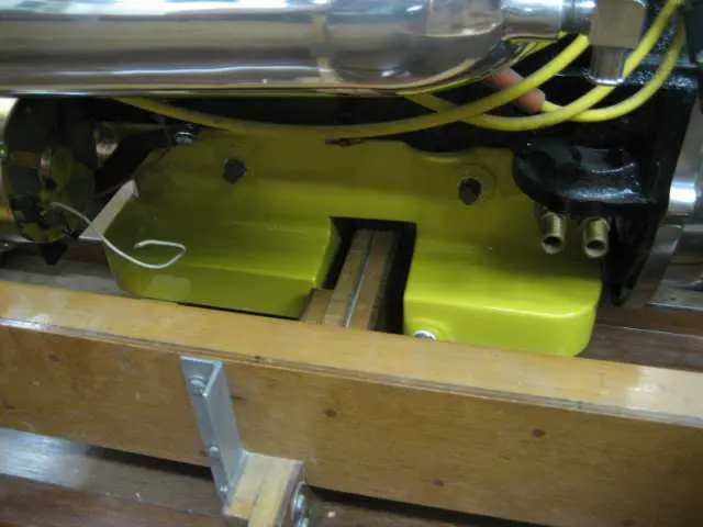
The two plugs at the top of the pan will be used to insert a hose into each sump. A rotary drill pump will make short work of oil changes. Several rounds of primer surfacer and block-sanding will be needed to get the substrate ready for paint. We're thinking of going with Corvette Yellow...
Pan interior will be chemically cleaned and have all seams sealed with multiple coats of DTM primer.
13 May 2007Paint & Finish
At last !
At last ! The finished product... Pan was shot with Dupont Uro-Prime primer-surfacer, block-sanded with 100 grit, reprimed, puttied, blocked with 180/220/320 grit, sealed, topcoated with white basecoat followed by Corvette Yellow basecoat and finished with several rounds of two-part Urethane Clear.
Pan interior was previously sealed with multiple coats of Dupont DTM primer.
22 May 2007Paint & Finish
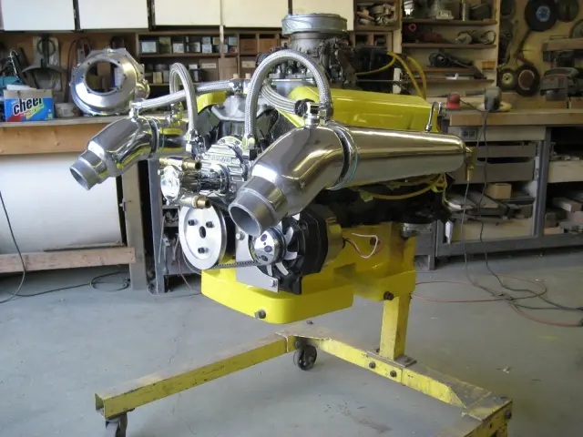
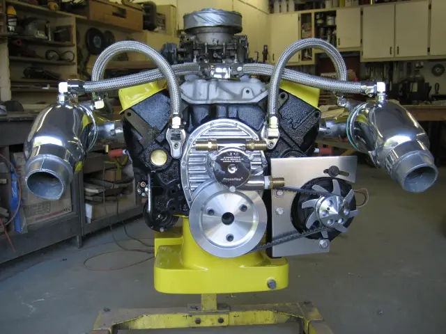
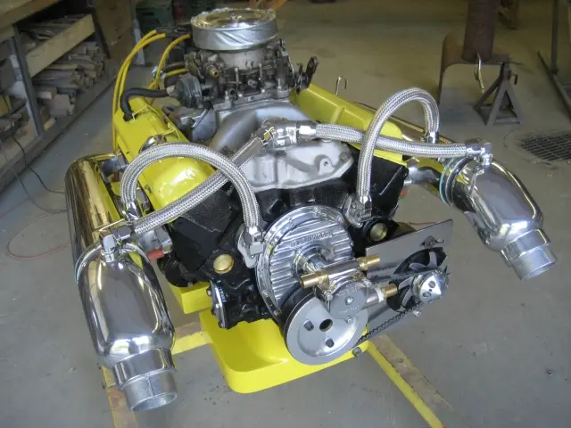
Over the weekend, we installed the oil pan, remote oil filter relocation kit, dipstick tube and the newly painted altern
Over the weekend, we installed the oil pan, remote oil filter relocation kit, dipstick tube and the newly painted alternator bracket. This engine is ready to install !
The stock stamped steel alternator pulley and fan were upgraded to lightweight aluminum billet pieces.
19 Jun 2007Systems
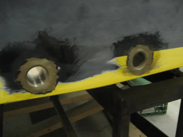
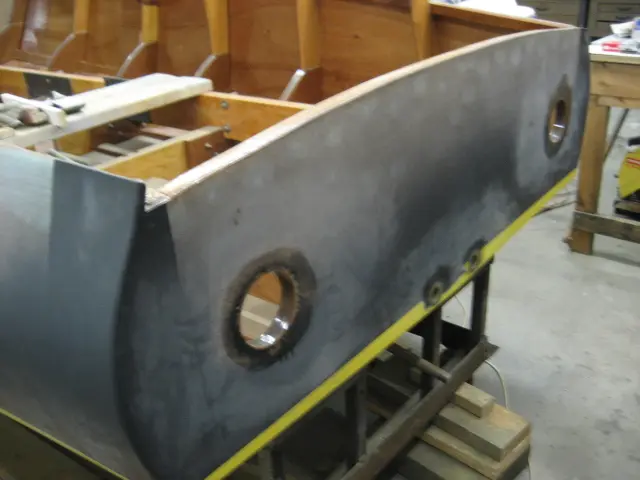
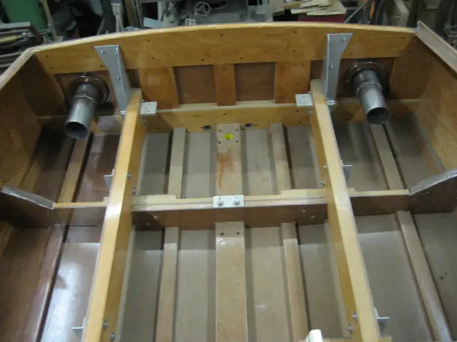
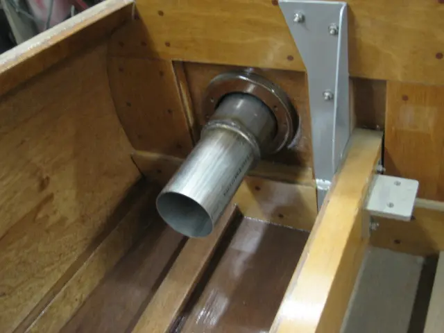
The transom drain plugs were cut out with a hole saw
The transom drain plugs were cut out with a hole saw. Fiberglass tubes were fabricated and epoxied into the holes.
A hole saw makes quick work of cutting out the exhaust outlet holes.
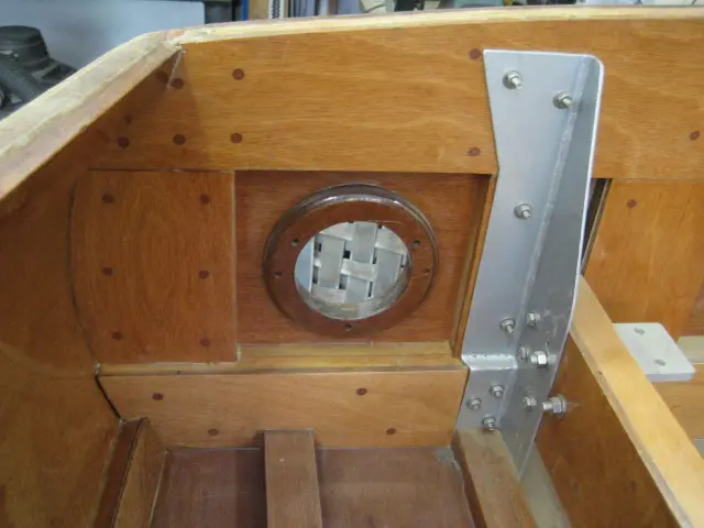
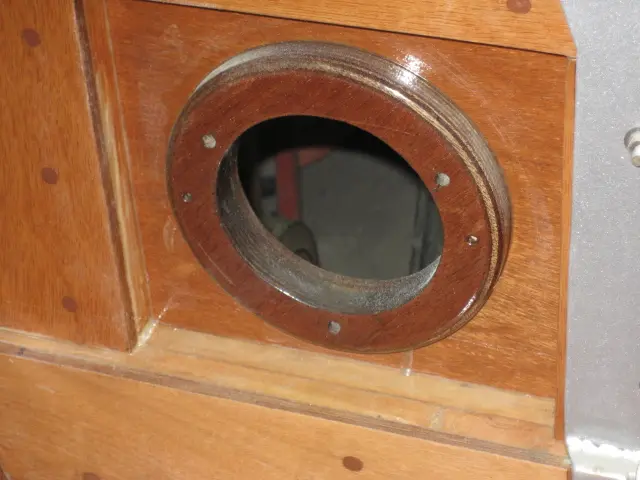
Interior view of the transom. A 3/4" marine plywood backing plate was fabricated and epoxied to the transom.
The inside lip was waterproofed with one layer of 6-1/2 ounce fiberglass cloth. The hole was drilled 1/8" oversize to allow a thick bead of sealant around the exhaust tip's circumference.
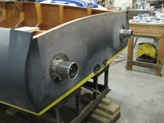
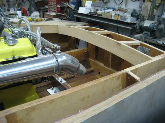
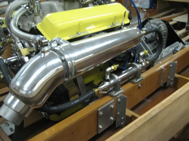
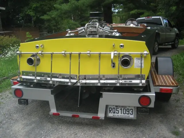
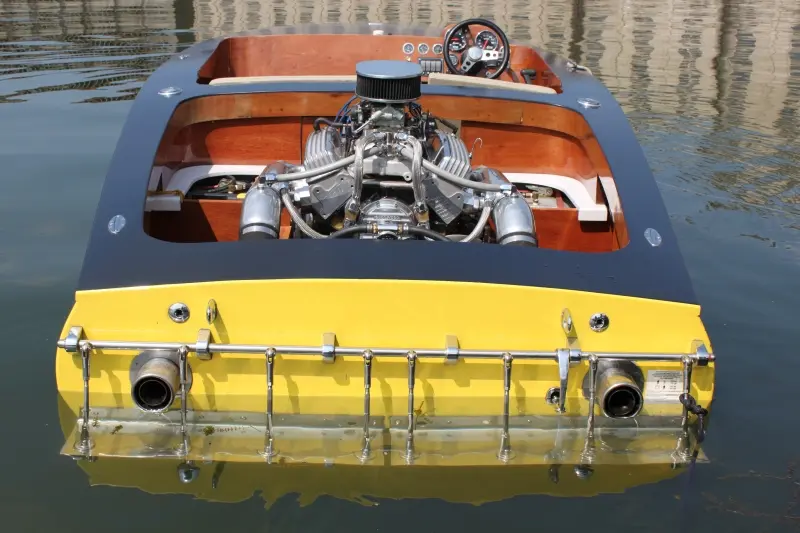
The Gibson Transom Mount Power Tip mufflers look sweet ! Click here to see the muffler specifications.
We reduced the 4" OD stainless pipe to 3-1/2".
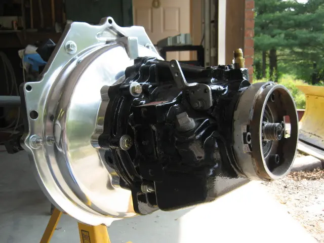
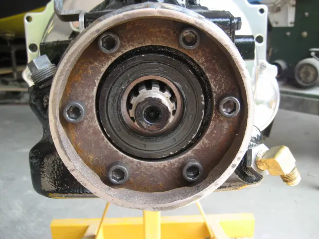
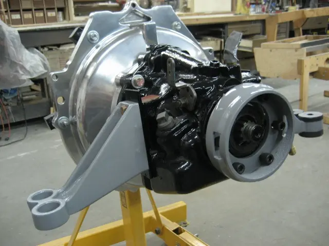
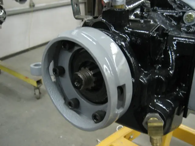
The rough-cast aluminum Velvet Drive bellhousing was brought back to life with many hours of sanding and polishing. We fabricated a torque tube guard adapter which mounts to the transnission's end-cover.
The cap bolts were replaced with hex head bolts in an effort to gain more clearance. The base was cut from a piece of 1/4" steel plate. A 1-1/2" wide slice from a 6" well casing was welded to a larger pipe which was in turn welded to the mounting plate.
With the transmission hub installed, there's just enough room to insert a hex key to tighten the end-cover bolts.
Slots cut into both sides of the part allow access to the hub bolts. I wasn't able to find a manufactured adapter, so like many parts on the boat, you have to build your own. It won't be a real Hot Rod unless it's got a bunch of homegrown parts on it !
11 Jul 2007Glassing & Epoxy
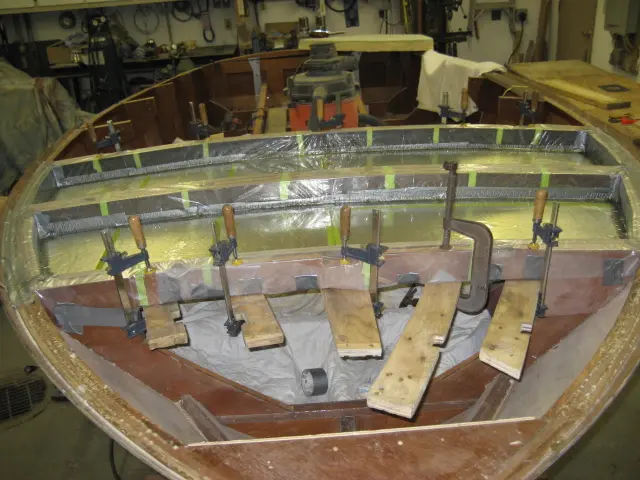
Here's the last of the interior epoxy barrier coating
Here's the last of the interior epoxy barrier coating. Round 2 will be followed up with a sprayed urethane clearcoat.
Once the clearcoat has been applied, we can start the carlings and deck !
17 Sep 2007Systems
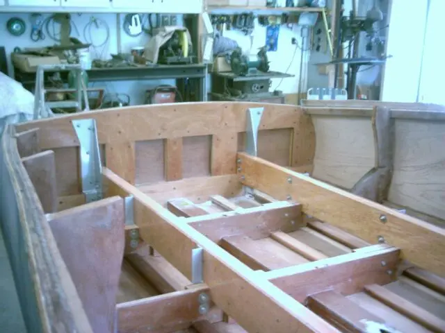
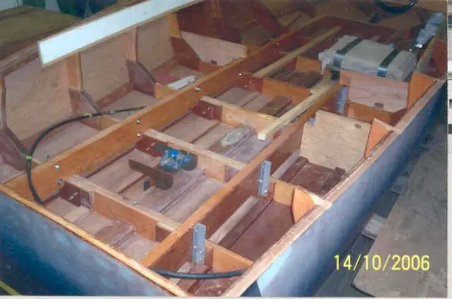
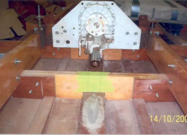
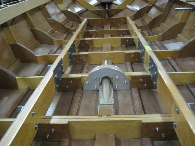
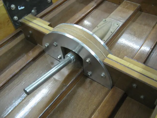
We fabricated a frame truss plate to span the stuffing box at frame # 4
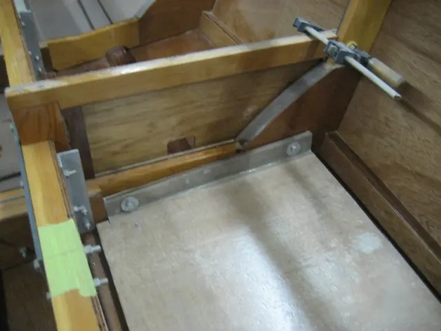
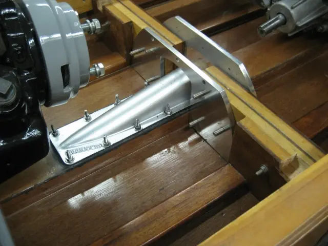
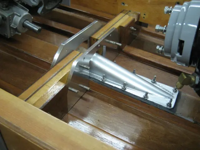
We fabricated a frame truss plate to span the stuffing box at frame # 4. It's made from 3/8" thick T356 aluminum plate. The v-drive and transmission mounting plates were bolted to the stringers with 3/8" stainless steel machine bolts. Also visible in the top left corner of the photo is the carling. We'll have more pics of this after it's been all glued up.
19 Nov 2007Fairing & Sanding
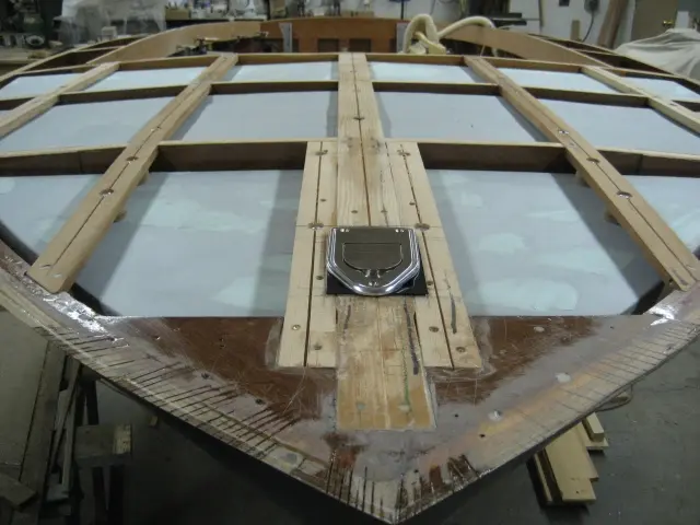
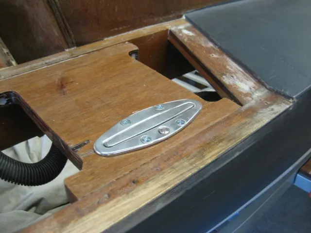
We'll be installing a stainless steel pop-up bow light in the strongback
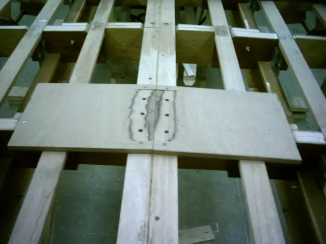
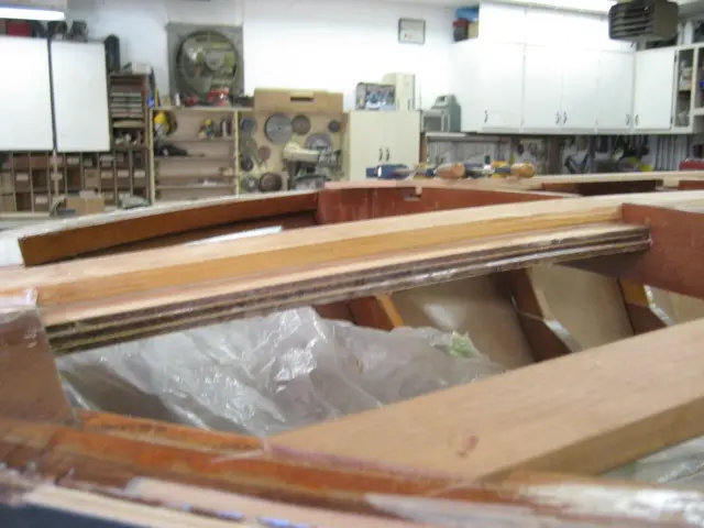
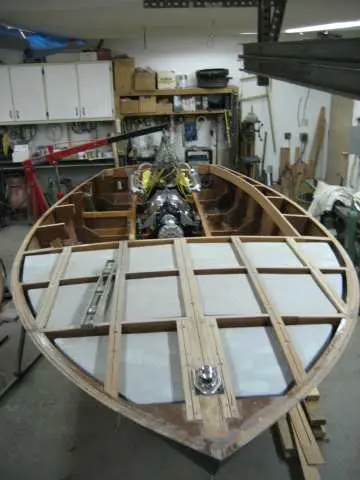
We'll be installing a stainless steel pop-up bow light in the strongback. This will require routing out a rather large hole which will seriously affect the member's integrity. We therefore laminated three pieces of 1/4" 5-ply marine grade plywood to the douglas fir strongback. This will retain it's curved shape.
Two douglas fir 1" x 2"'s were laminated to the plywood strips. A 3/8" dado was cut into the stock and the breasthook was routed to a depth of 3/8" to receive the two pieces.
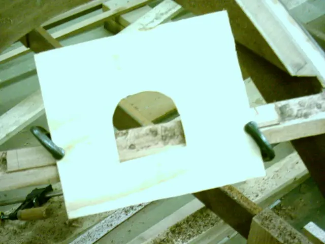
Initial deck fairing completed. Now we'll have to lay out and cut an opening for the pop-up bow light.
Chapter 10
Hardware & Fit-Out
Cleats, rudder and centerboard, tiller, oarlocks, deck gear.
6 daysfrom December 2007
23 Dec 2007Hardware & Fit-Out
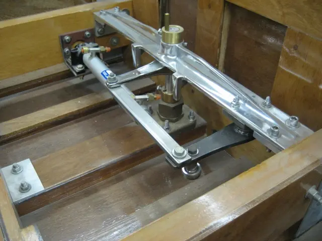
Steve at Ayling's Boat Yard has been busy in the machine shop refining the steering components
Steve at Ayling's Boat Yard has been busy in the machine shop refining the steering components. The slave tiller arm bushing housing was welded, the pivot pin was upgraded to 3/4" diameter stock and re-bushed to tighter tolerances. Nice work, Steve ! Click here to see more detailed photos. ( a new window will be opened)
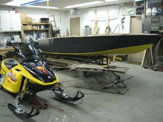
Work on the boat will continue over the holidays, but we'll also make some time to enjoy the snowmobile trails. Can't be working in the shop all the time ! I'd like to wish all our visitors a Merry Christmas and a happy New Year !
24 Dec 2007Deck & Coamings
Under-deck flotation billets were cast and installed
Under-deck flotation billets were cast and installed. Click here to see more detailed photos. ( a new window will be opened)
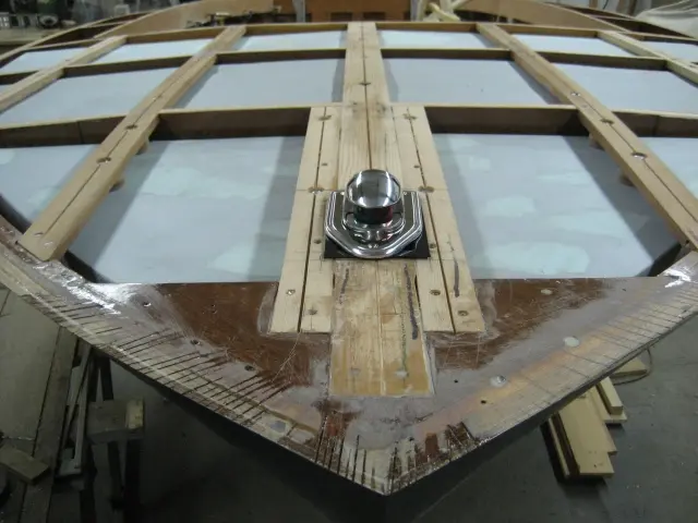
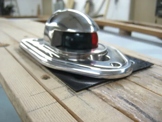
For a sleek contemporary look, we've chosen a stainless steel pop-up bow light. When not in use, it's flush with the deck...
... and pops up when needed.
The bow light is housed in a plastic receptacle which can be equipped with a hose barb and drain hose. This unit was purchased from Marine Toys in Delta, British Columbia. See our Links Page for supplier information. ( a new window will be opened)
25 Feb 2008Paint & Finish
Time flies when you're having fun !
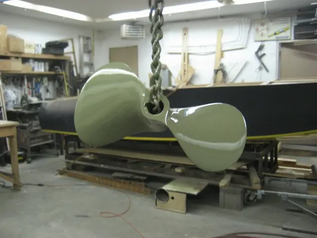
Time flies when you're having fun ! It's time to get back to the boat and get her finished up... First order of the day was to prime the Menkens 2-blade propeller we picked up before Christmas. It's an 11-1/2" diameter by 15" pitch forged steel unit which should allow the engine to spin into the stratosphere... The part was etched and cleaned with DuPont Metal conditionner. This was followed by two rounds of DuPont 2580CR DTM Urethane Primer.
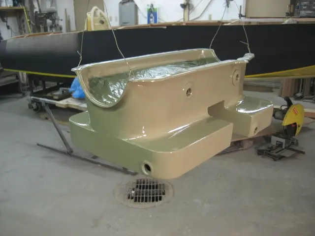
Here's a photo of the fuel tank platform we molded several months ago.
A piece of 1/4" marine-grade plywood was sandwiched between multiple layers of 6-1/2 ounce fiberglass cloth and 2 ounce mat. The radiused edges were built up from several cloth laminations.
The cradles are bolted to frames # 3 and # 4. A 3/8" gap was left between the cradle and bottom battens.
Spacers will be fabricated to space out the cradle from the frame. This will ensure adequate drainage and ventilation between the two parts.
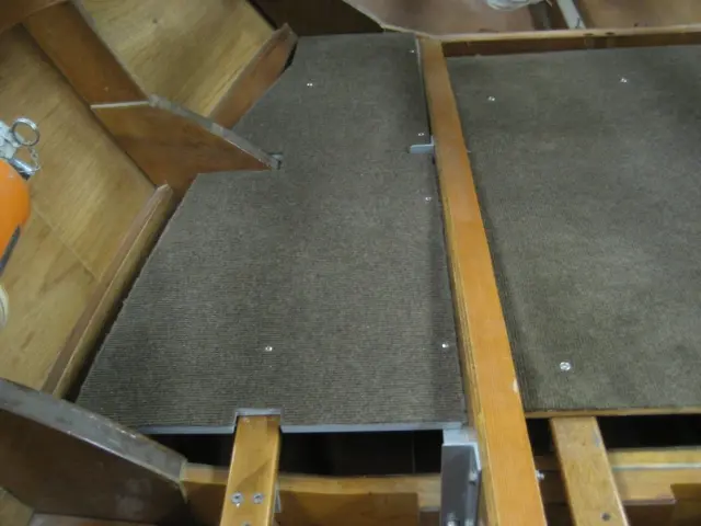
The rear jump seat's front panel is being fitted. The intent is to bolt the jump seat supports so they can be easily removed in the future.
Chapter 11
Sea Trials & Shakedown
First sails or runs, trim, tuning, and the punch list that follows.
3 daysfrom April 2008
7 Apr 2008Sea Trials & Shakedown
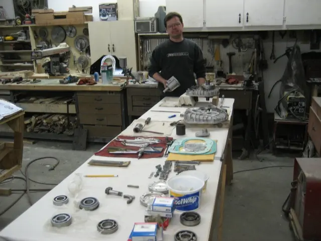
Here's a good friend of mine, Colin, rebuilding the v-drive
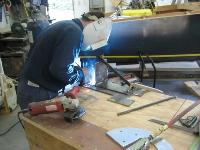
Here's a good friend of mine, Colin, rebuilding the v-drive. It's nice to have a Class A mechanic in the shop ! He's rebuilt the engine and is our ace fabricator / welder. He enjoys working on the mechanical components of the boat but is quite emphatic about staying on firm ground on launch day...
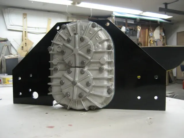
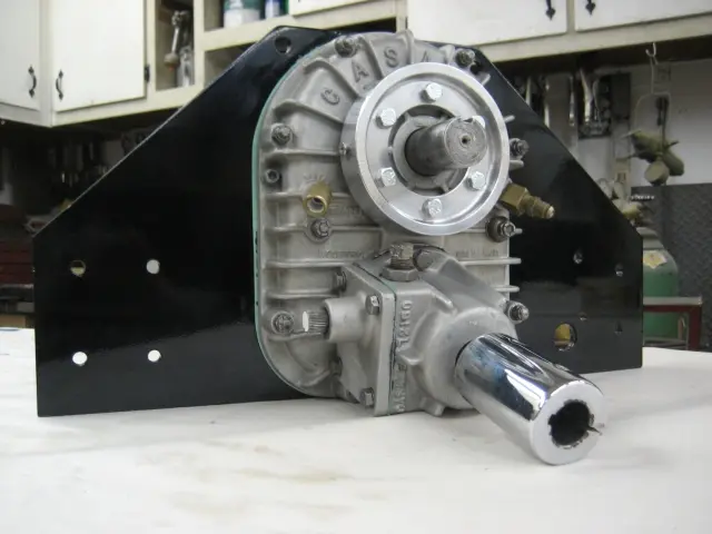
Before you know it, the v-drive is fully assembled. The v-drive plate was painted before final assembly. The plate was pretty rough, so we blocked it out with several coats of epoxy primer. This was followed up with Dupont 280CR DTM primer, Dupont Uro-Prime urethane primer-surfacer and topcoated with Dupont Imron urethane enamel.
It's important to note that the gasket mating surfaces should not be painted as the paint film buildup will change the v-drive's internal tolerances. Related Links : Casale Direct Drive Dimensional Drawing Casale In-Out Dimensional Drawing
14 Apr 2008Paint & Finish
Here's the last of the mechanical components being painted
Here's the last of the mechanical components being painted. H-joint assembly, v-drive shifter, transmission mounts, v-drive flange takeoff, torque tube guards and transmission takeoff adapter.
The transmission mounts were installed with grade 8 bolts.
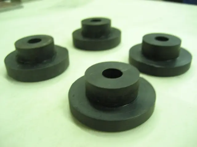
The old soft rubber bushings were removed...
... and replaced with custom Delrin bushings. These are more of Steve Flewitt's handiwork !
The solid mounts will prevent the engine and transmission from flexing under heavy torque loads.
The custom torque tube guard adapter is being installed.
29 Apr 2008Systems
Here's the day I've been waiting for !
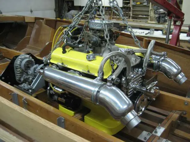
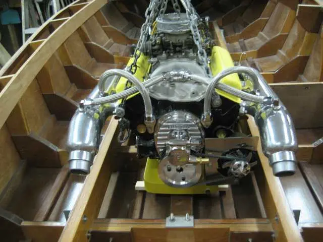
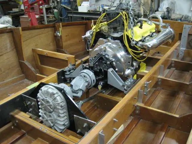
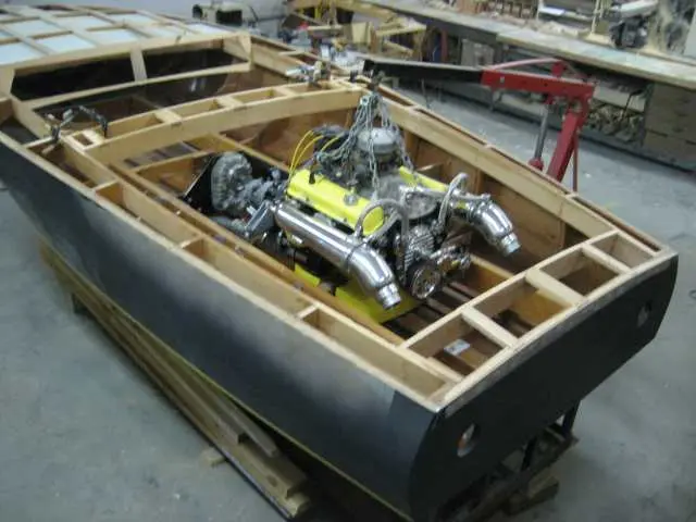
Here's the day I've been waiting for ! Engine, transmission and v-drive installed with very few issues.
We don't have enough clearance between the torque tube guard adapter and the v-drive take-off hub. The hex-head bolts used to retain the guard will have to be swapped out for flat head machine bolts.
Here's a close-up of the oilpan straddling frame # 2.
Oil capacity has been expanded from 4 quarts to 12 quarts.
The custom oil pan lowered the engine by 3-1/2". A lot of work, but the engine is horizontal and nicely nestled into the boat.
20 May 2008Systems
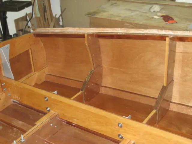
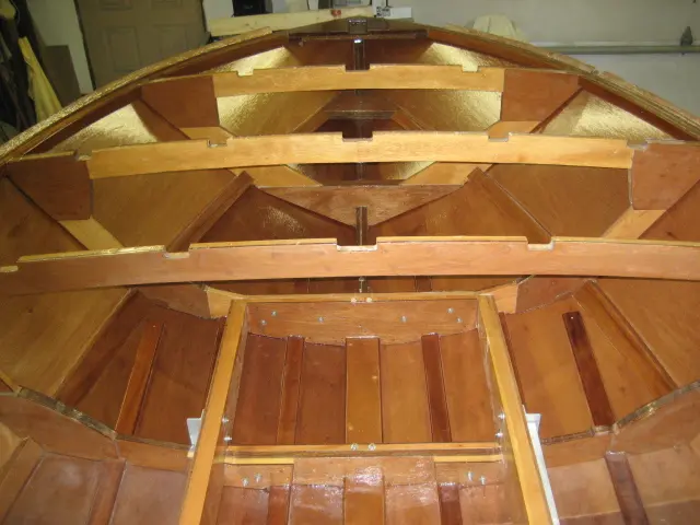
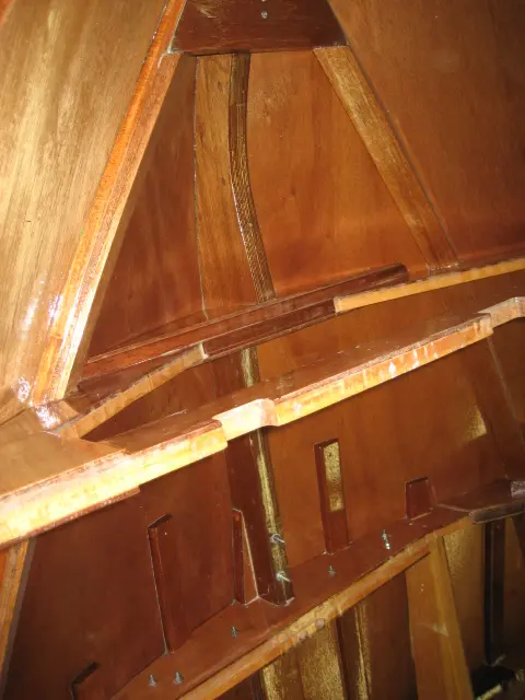
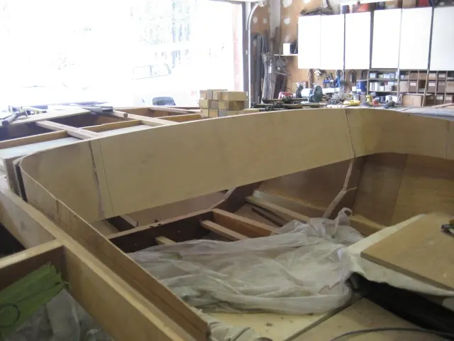
The intermediate deck beam straddles the carlings at frame # 4
The intermediate deck beam straddles the carlings at frame # 4.
Coaming corners were radiused with plywood veneer. We ran some 1/8" marine- grade mahogany plywood through the planer to remove one face. This makes it much easier to bend !
Transom deck beam is 9" wide.
The bottom edge of the beam was molded to a width of 3-1/2".
View from the transom.
Here's my friend Colin finish-welding up the v-drive mounting plate. We spent the day finalizing the transmission mounts. With all components bolted in, we measured for the propeller shaft.
2 Jul 2008Hardware & Fit-Out
The driver's seat is nearing completion
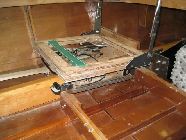
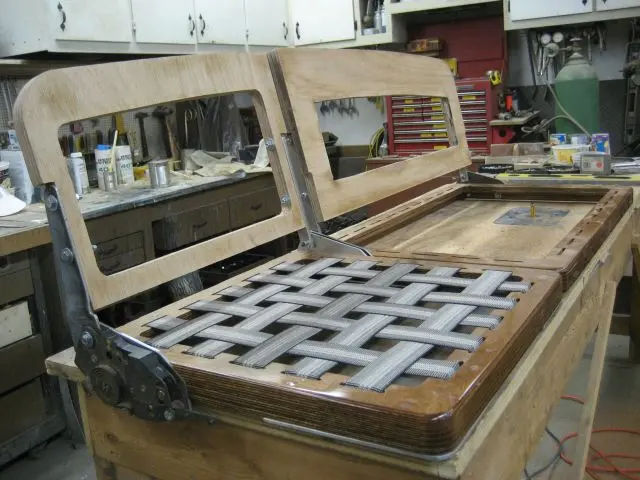
The driver's seat is nearing completion. The rails provide 6" of horizontal travel, 3" of vertical travel at the front of the seat and reclining backrest. We've also started the passenger seat base. Click here to see how the seat was made. ( a new window will be opened)
26 Aug 2008Paint & Finish
All mounting plates were sandblasted, primed and painted before final assembly
All mounting plates were sandblasted, primed and painted before final assembly. We've added triangular webs along the v-drive's thrust centerline to stiffen up the v-drive plate.
The stuffing box was installed with stainless steel hanger bolts.
The frame truss plate was cut down to conform to the bottom of the transmission.
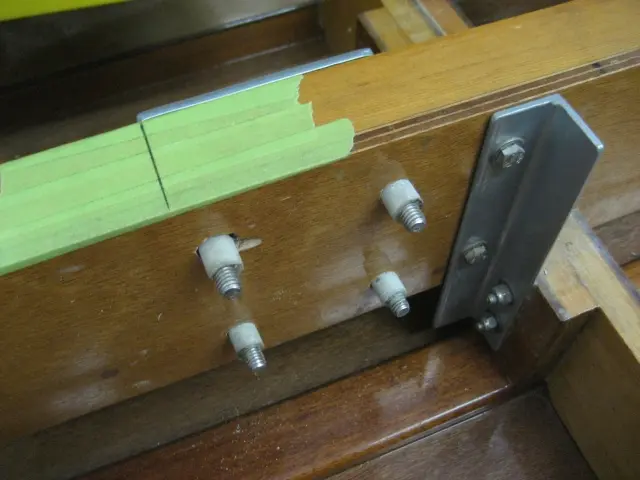
The front engine mount stringer bolt holes were bushed with fiberglass bushings.
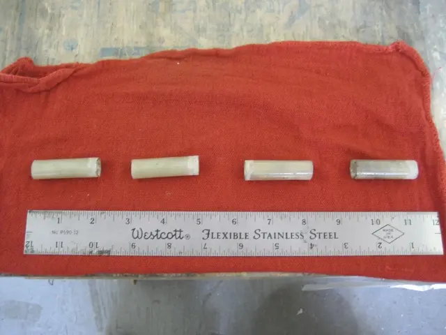
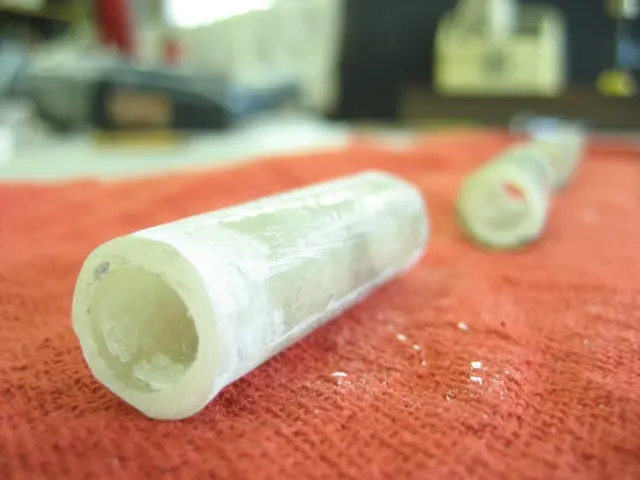
The tubes were epoxied into the bolt hole bores and allowed to cure.
Bushings were fabricated from 6-1/2 ounce fiberglass cloth.
There's no limit as to what can be done with epoxy and fiberglass !
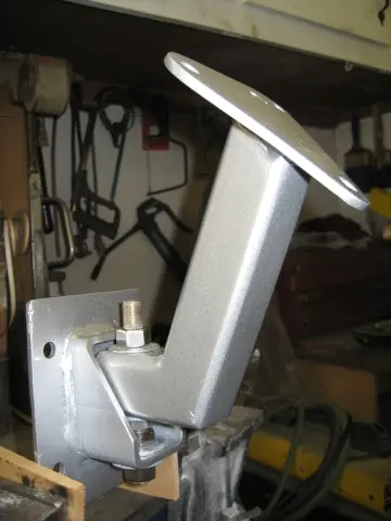
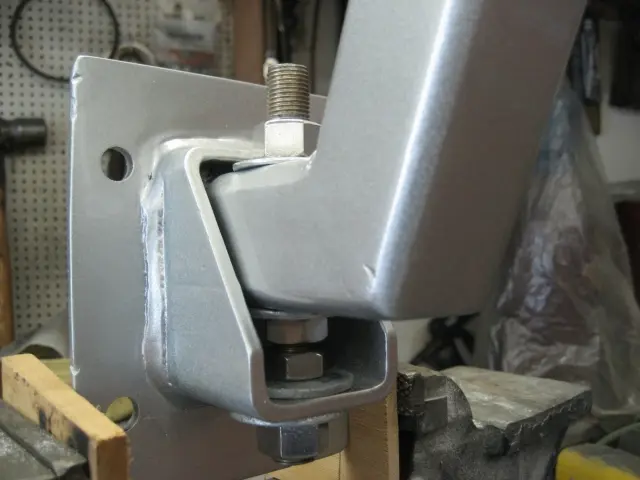
We fabricated adjustable front engine mounts using flat plate and tubular steel.
Vertical travel can be adjusted by turning the 1/2" nut located beneath the strut.
3 Nov 2008Systems
The Hardin Marine thermostat housing required us to re-plumb most of the engine plumbing
The Hardin Marine thermostat housing required us to re-plumb most of the engine plumbing.
A Glenwood oil cooler was mounted to the stringer. This should reduce engine oil temperature and increase engine life.
Yet another Glenwood oil cooler was installed below the Velvet Drive's fill plug level. This adds extra capacity to the system and ensures that the trans is at its maximum fill level at all times.
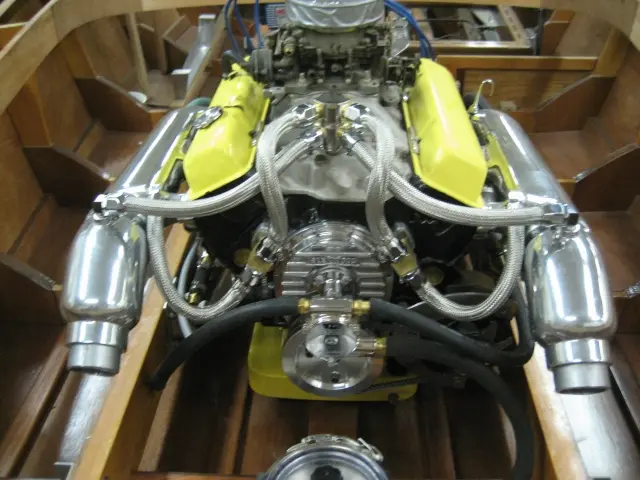
An MSD billet aluminum marine distributor, digital ignition box complete the engine installation.
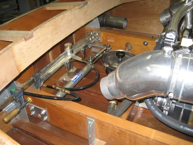
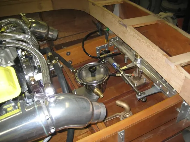
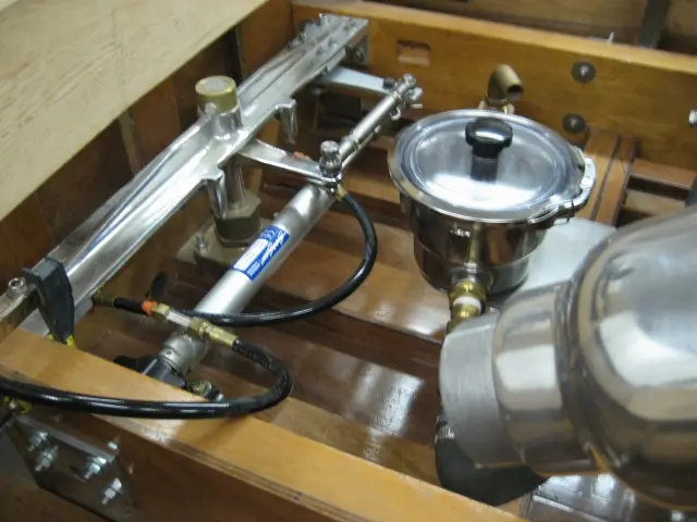
Last of the hydraulic steering components were installed.
A Gil offshore sea strainer filters raw water before feeding it into the cam-driven water pump and oil coolers.
20 Nov 2008Trailer & Gear
Moving the boat from its cradle to the trailer went extremely well
Moving the boat from its cradle to the trailer went extremely well. The 6" wide x 12' long I-beam is supported by jackposts which adjust from 7' to 9' in height. The 3" C-channel base is supported by 8" steel casters. Note the freshly carpeted trailer bunks.
21 Nov 2008Trailer & Gear
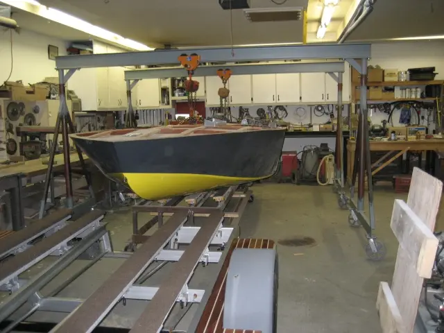
Time spent building the gantry was well worth it
Time spent building the gantry was well worth it. Any failure at this stage would be catastrophic ! The boat's on the trailer... We've loaded up the truck... We've got a full tank of gas... We're off to Alabama !
16 Dec 2008Trailer & Gear
Several days (and kilometers) later
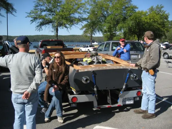
Several days (and kilometers) later... It's Saturday, October 25, mid sixties and we're lined up in the Guntersville Lake State Park, Alabama parking lot. Gayle Brantuk, Vice President of Glen-L Marine Designs takes a break on the Hot Rod's trailer fender step. She and her husband John flew in from Bellflower, California to attend the event. Click here to see some photos of the event and our boatbuilder interview.
23 Mar 2009Systems
We've been working away at the boat over the winter but haven't much to show so far
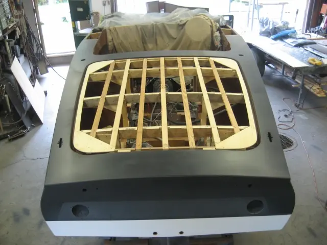
We've been working away at the boat over the winter but haven't much to show so far. Work on the cockpit continues. Over the next few weeks, we'll be laminating several layers of.100" veneer over the carlings. This will give a nice smooth radius to the inside corners. Click here to see how it was done.
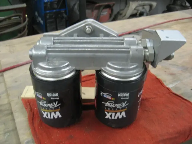
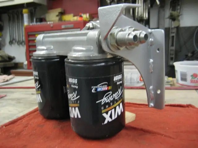
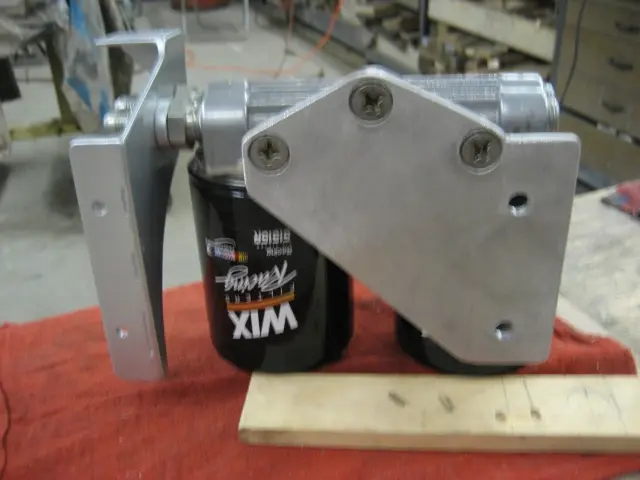
We fabricated a custom support bracket for the remote dual oil filters.
A bulkhead fitting connects the bracket to the oil filter head assembly.
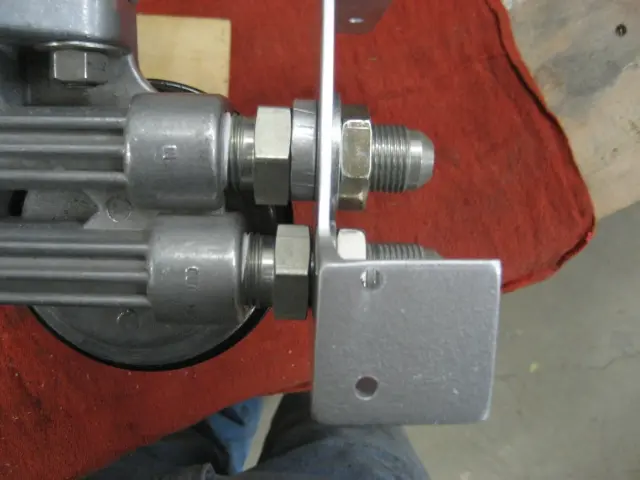
The two holes on the right of the photo mount to the v-drive mounting plate.
4 May 2009Systems
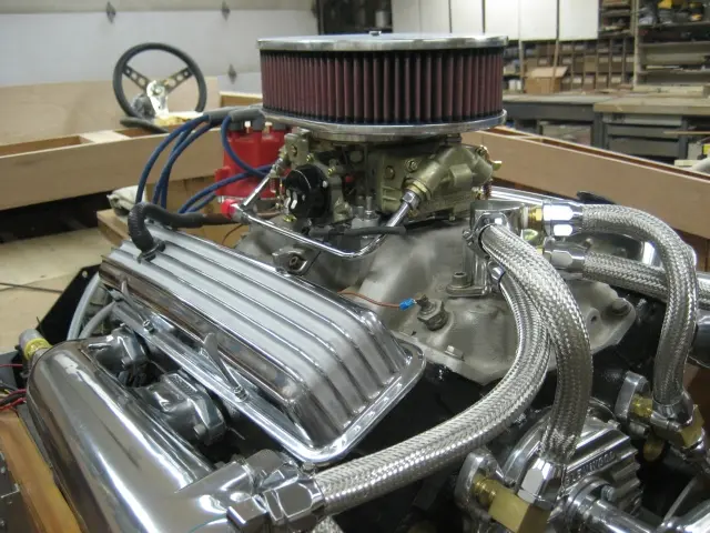
The original Carter 3660 carburetor was upgraded to a Holley 600 CFM marine four barrel carburetor
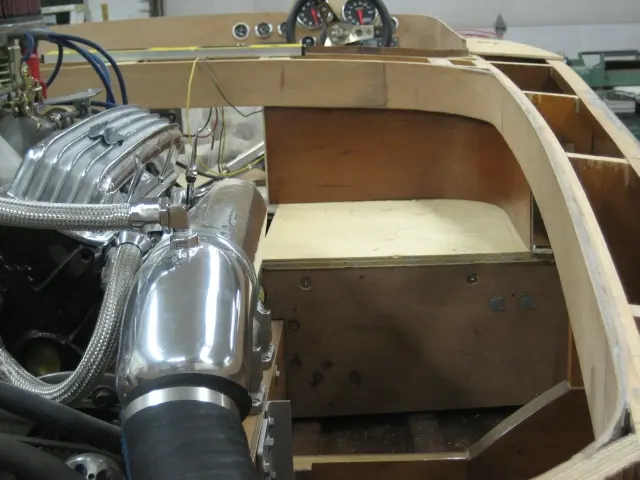
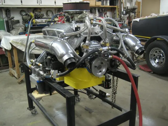
The original Carter 3660 carburetor was upgraded to a Holley 600 CFM marine four barrel carburetor. The Hardin Marine flame arrestor uses a K&N air filter capable of flowing 30% more air than a stock flame arrestor. Also visible in the background is a steering wheel connected to a Teleflex hydraulic SeaStar Pro Tilt helm. Click here to see more detailed engine photos.
4 May 2009Deck & Coamings
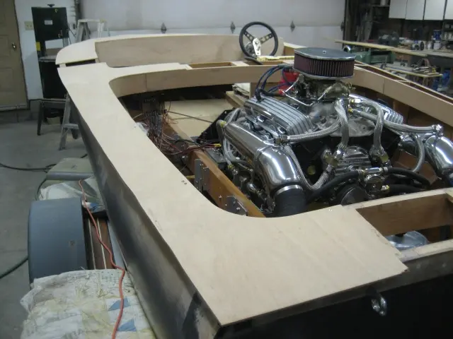
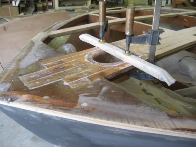
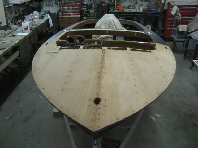
We're finally trial fitting the deck panels
We're finally trial fitting the deck panels. Click here to see more photos.
4 May 2009Hardware & Fit-Out
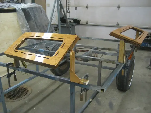
Work on the front cockpit carlings and dash continues
Work on the front cockpit carlings and dash continues. We've snapped a lot of pictures to describe the process. Click here to see how it was done.
15 Jun 2009Hardware & Fit-Out
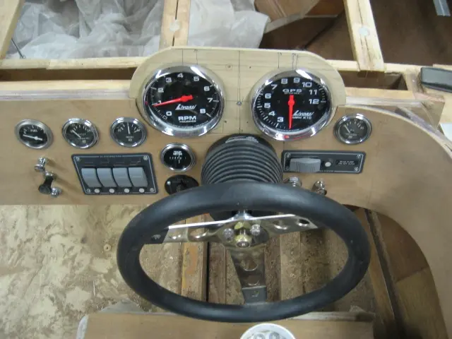
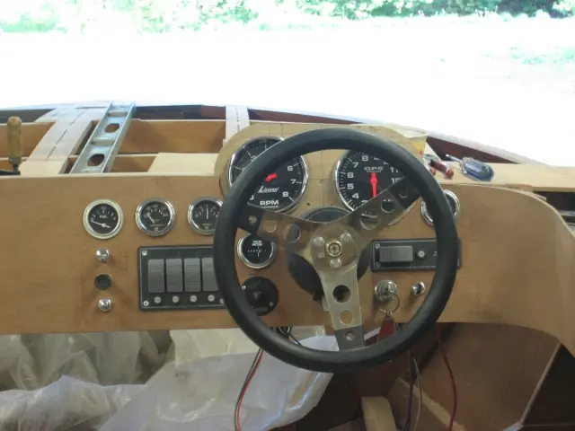
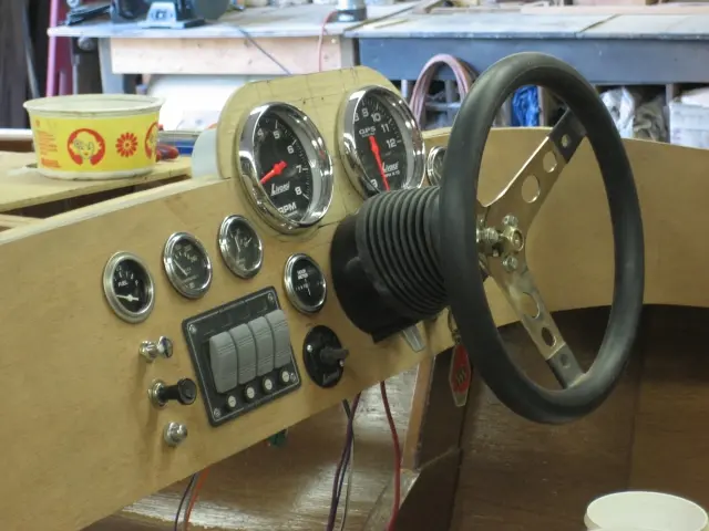
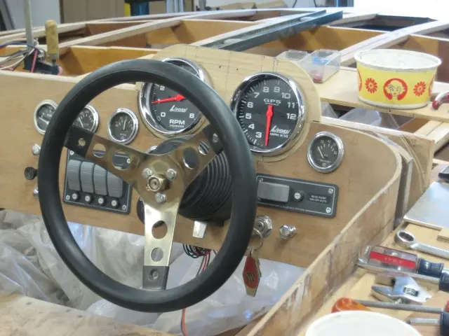
Gauges were installed over the weekend and are ready for wiring
Gauges were installed over the weekend and are ready for wiring. The helm is a SeaStar Pro Tilt hydraulic unit. 5" Monster GPS speedometer and tachometer are made by Livorsi. The water temperature, oil pressure and volt meter gauges are vintage VDO units salvaged from a Chris-Craft cabin cruiser. The fuel level and hour meter gauges are Teleflex Heavy Duty gauges. Rocker switches are fully waterproof. GPS speedometer recall/reset toggle switch is located to the left of the helm. There's still another layer of mahogany veneer to apply on the dash before applying the final finish clear coats.
3 Jul 2009Hardware & Fit-Out
We extended the radiused corner coamings to the the rear jump seat backs
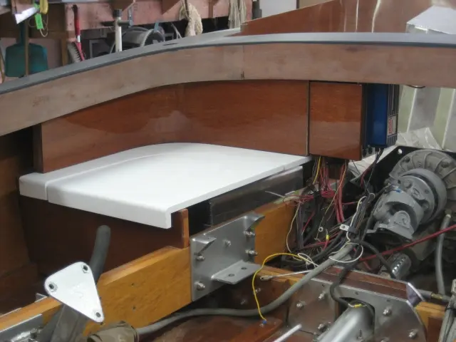
We extended the radiused corner coamings to the the rear jump seat backs. Since this photo was taken, the seat supports have been veneered and topcoated with several coats of epoxy and automotive clearcoat We're holding off on final assembly until the fuel tank cradles and battery box are installed.
9 Jul 2009Hardware & Fit-Out
Fuel tank cradles are ready to install
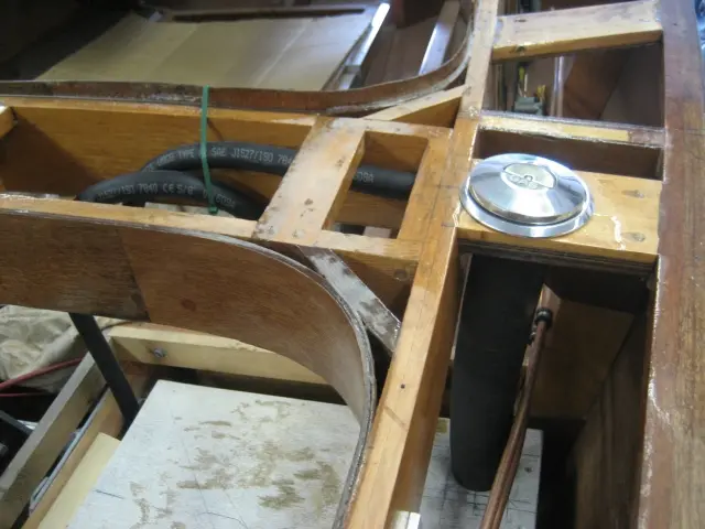
Fuel tank cradles are ready to install. Click here to see the fuel tank cradle and jump seat construction photos.
23 Aug 2009Sea Trials & Shakedown
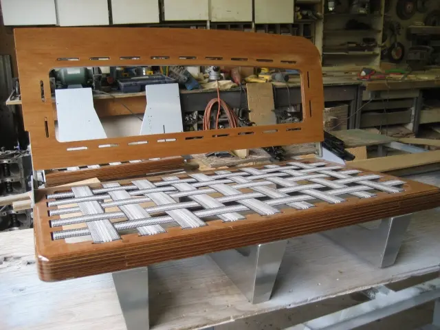
One of the last interior jobs is to finish up the front cockpit seating
One of the last interior jobs is to finish up the front cockpit seating. Click here to see our work in progress.
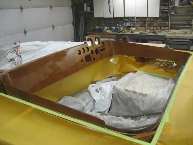
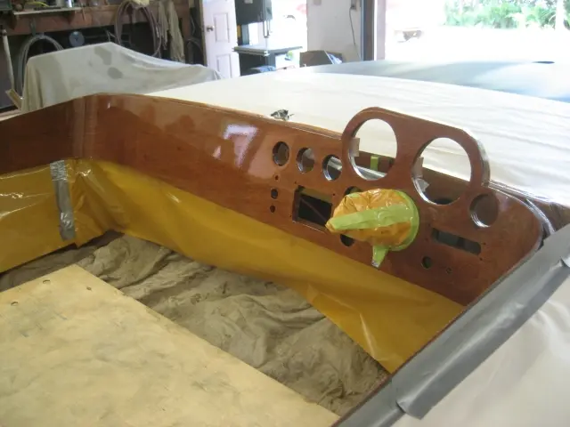
Time for some serious finishing ! Dash and front cockpit carlings received three rounds of epoxy (block sanded between coats) and 2 rounds of Perfection 2 part varnish. This is not the final veneer layer for the dash and carlings. We'll be adding a more exotic veneer over the Winter months !
Click the 'Play' button (>) to see the video. Glen-L Hot Rod - First Startup
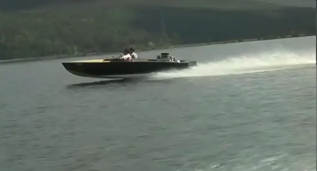
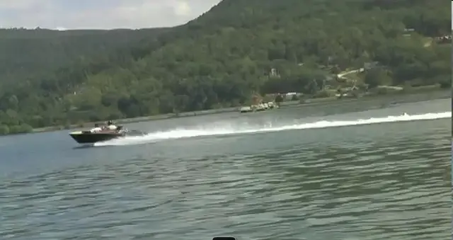
Glen-L Hot Rod Sea Trial Glen-L Boatbuilder Gathering, Guntersville Alabama, October 23-25 2009 We haven't been updating the website for awhile because we wanted to get the boat ready for the third annual Glen-L Boatbuilder Gathering, held at Guntersville Lake State Park, Alabama, October 23-25. We came up short on the decking and upholstery, but neither were needed for the Hot Rod's Trial Launch. Gayle Brantuk, Vice President of Glen-L Marine Designs and her husband John flew in from Bellflower, California to attend the event. They were accompanied by Allyn, the man responsible for crafting Glen-L's frame kits and test boats. Last year, Gayle was happy to visit us in the Park's parking lot where all the 'Work in Progress' boats were displayed. This year, she got to drive it !. Needless to say a good time was had by all who attended the get-together. It just doesn't get any better than this ! Click here to see Glen-L Gathering photos and videos.
Click the 'Play' button (>) to see the video. Hot Rod Sea Trial 2 - Ottawa River Run [HD] (CyberNick)
31 Mar 2010Sea Trials & Shakedown
It's been a long time since our last update
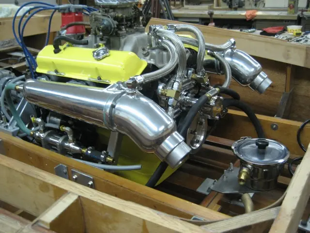
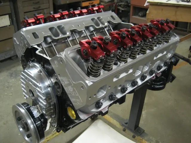
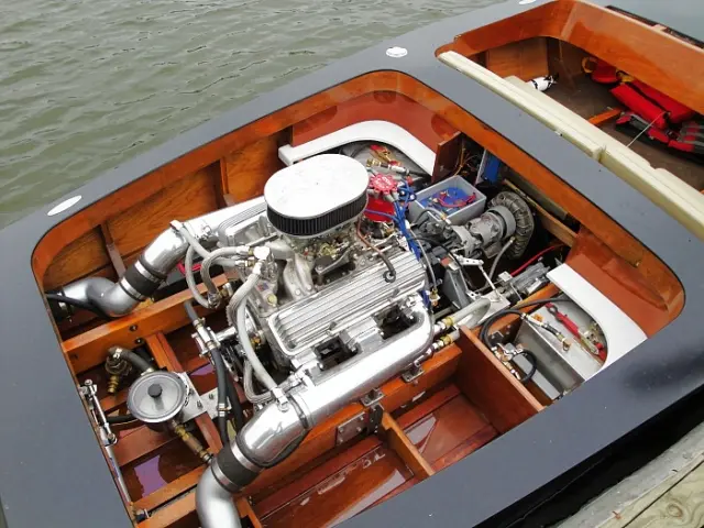
It's been a long time since our last update. We've clocked 12 hours on the engine since our launch last October. It has performed flawlessly but we expect that the hydraulic camshaft won't stand up to sustained high RPM usage. Last month, we pulled the Hot Rod's 355 Chevy engine and will be upgrading it for severe duty service. This includes installation of a main bearing stud kit, Air Flow Research aluminum cylinder heads, hydraulic roller camshaft, aluminum roller rocker arms and an Edelbrock RPM Air Gap intake manifold.
Click here to see more engine assembly photos.
Click the 'Play' button (>) to see the video. Glen-L Hot Rod - 355 Marine Engine Startup
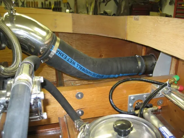
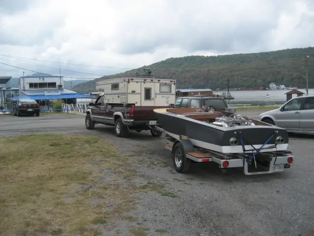
Glen-L Boat Builder Gathering - September 25-26 2010, Lake Nickajack, Tennessee The Gathering is a get together of boat builders, family and friends organized by Glen-L builders. The Hot Rod made the trip again this year. After scouring the want ads for several months, we found a used Palomino pop-up truck camper for a reasonable price. The passenger-side box wing was replaced with a new fiberglass-laminated plywood panel and the driver-side box wing was reinforced with fiberglass cloth and aluminum plates to support the camper tie-down straps. The original two-way refrigerator was upgraded to a new three-way unit (propane, 12 volt DC and 120 volt AC). The camper and tow vehicle's wiring were also redone. Photo coutesy of John Brantuk, Glen-L Marine Designs We didn't have enough time to get the boat ready before we left for Tennessee, so we finished up the wiring, fuel lines and exhaust hoses before launching the boat on the Thursday afternoon. The boat ran great and the new propeller is a big improvement over the prop we ran last year ! Photo coutesy of Gayle Brantuk, Glen-L Marine Designs Click here to browse our Trip Report, photos and videos of the event.
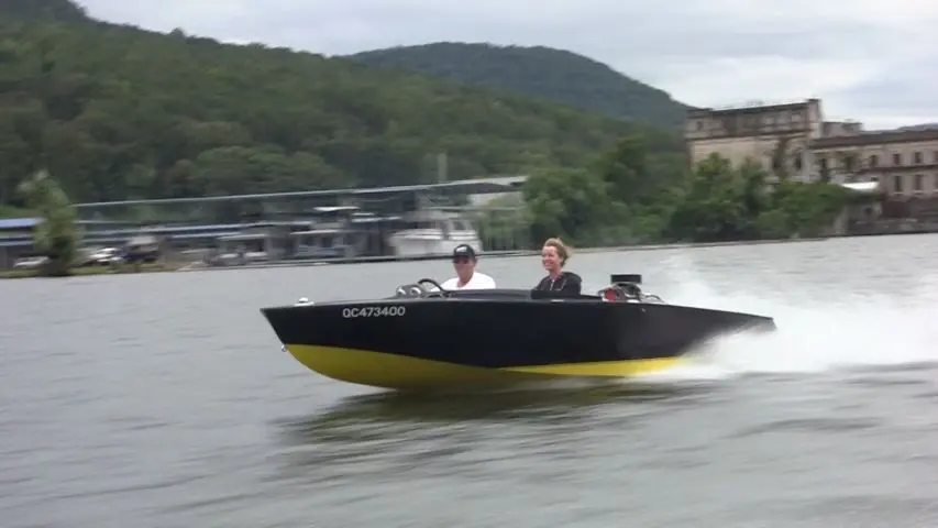
It's over for another season... We've logged 18 hours on the clock since we got back from G4. Actually using the boat has to be the best part about boatbuilding ! We shot some footage on our second last run and thought we'd share it with you. So hang onto your tuque (temp was 36° F!), we're going for a ride... Click the 'Play' button (>) to see the video. Glen-L Hot Rod Boat Cruise - Ottawa River 2010 (HD)
23 Jul 2011Systems
At the Glen-L Boatbuilder Gathering, Lake Nickajack, Tennessee
At the Glen-L Boatbuilder Gathering, Lake Nickajack, Tennessee. Photo courtesy of Gayle Brantuk, Glen-L Marine Designs Click on the links below to see the latest updates. Seats Deck Exhaust System
Gathering of Glen-L Boatbuilders at Lake Nickajack Tennessee, September 16-18, 2011. We attended the fifth annual get together of Glen-L boat builders, family and friends organized by Glen-L builders. Photo courtesy of Gayle Brantuk, Glen-L Marine Designs Click on the link below for more details : Gathering 2011 Trip Report and Photos
23 Jul 2011Paint & Finish
The boat has been reassembled and is back on the water !
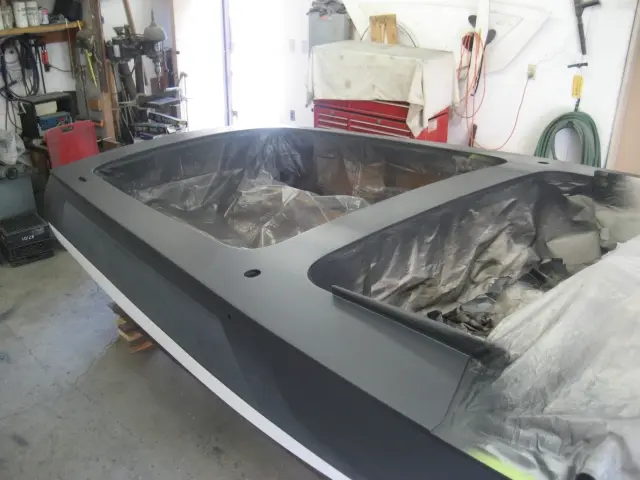
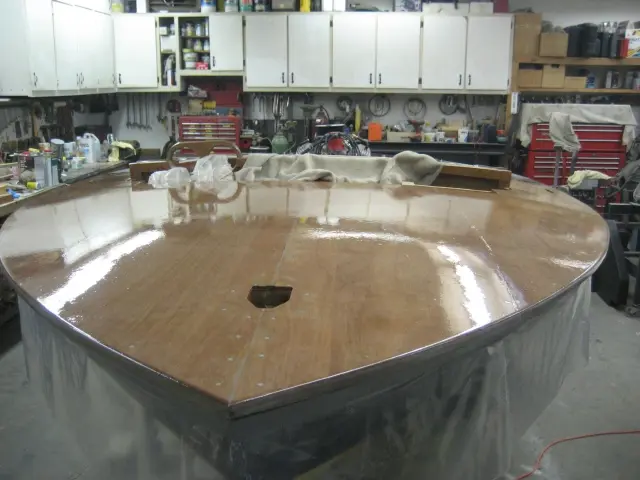
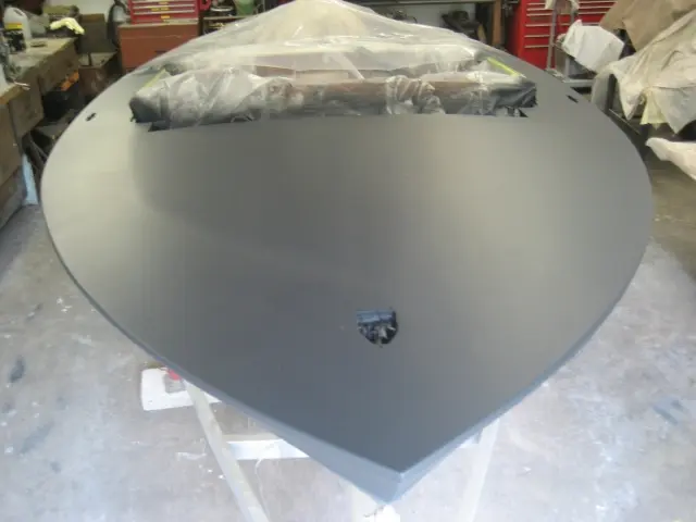
The boat has been reassembled and is back on the water !. The deck and hull have been sealed with two rounds of black primer-sealer. The shortened propeller shaft and new smaller diameter propeller have been installed. The front seats and cockpit have been reassembled.
Clearcoating the dash.
Fresh coat of black urethane primer sealer.
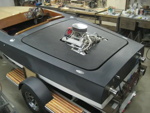
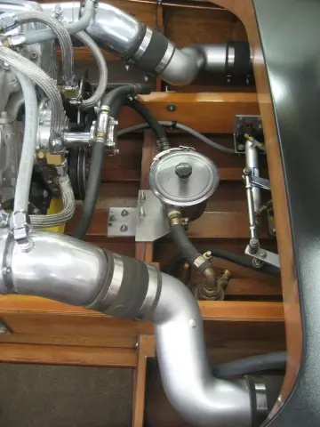
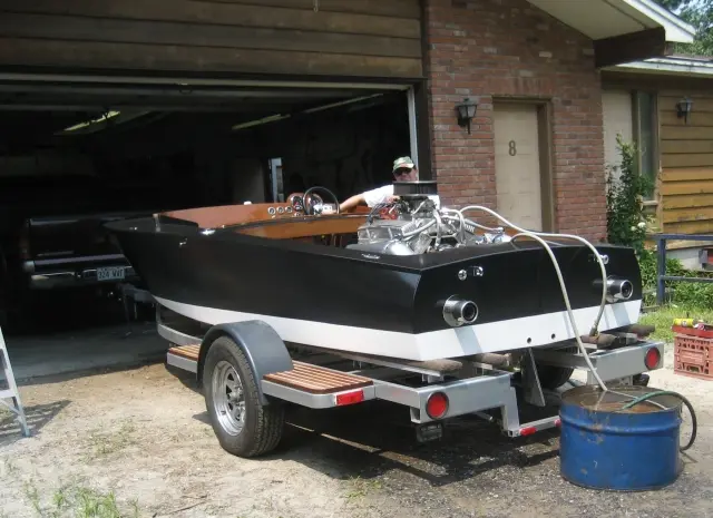
Upgraded rubber exhaust hoses to custom aluminum "S" pipes.
First startup of the season.
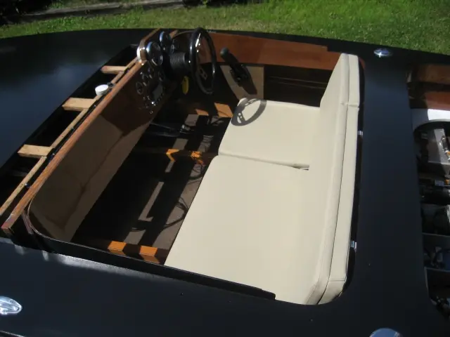
New removable upholstery !
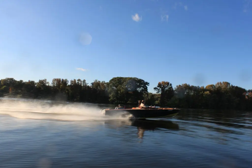
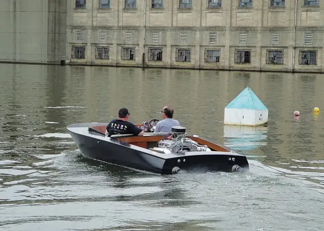
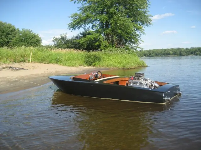
At Lower Duck Island on the Ottawa River.
25 Aug 2012Strongback & Molds
Latest Updates It has been a while since our last update !
Latest Updates It has been a while since our last update ! We've been busy installing an adjustable cavitation plate on the boat. The installation required pulling the starboard fuel tank and fabricating a new shaft to mount the cavitation plate pedal and gas pedal. We also shot some Corvette Yellow on the transom while we were at it. We hope to have the boat back in the water early next week. We'll be leaving September 3rd for the 1200 mile ride to the 2012 edition of the Glen-L Boatbuilder Gathering at Lake Nickajack, Tennessee, September 7-9 2012. Click here to see the cavitation plate installation photos.
Gathering of Glen-L Boatbuilders at Lake Nickajack Tennessee, September 7-9, 2012. We had a great time at the 2012 edition of the Glen-L Boatbuilder Gathering held at Lake Nickajack, Tennessee. wnd would like to thank everyone who made it happen. The hospitality and camaraderie at this event keeps us coming back every year ! We're already making plans for next year... Here's the first cut of Gayle Brantuk's ride in the Hot Rod : Click the 'Play' button (>) to see the video. I'd like to thank Gayle for taking time out from her busy schedule to attend the Gathering, Neel Thompson for providing the video chase boat and Nick for shooting the video. We'll post more videos soon ! Click on the links below to see more : G6 was G-Great! (Glen-L Boatbuilder Blogs, posted by Gayle Brantuk) G6 Boat Videos (Glen-L Boatbuilder Forum, posted by Mr. Hot Rod) Gathering 2012 Photos (Glen-L Boatbuilding Galleries) Gathering 2012 (Thread on Glen-L's Boatbuilder Forum ) Glen-L Boat Video Directory - Gathering videos (2007-2012) (KaneCustomBoats.com)
Gathering of Glen-L Boatbuilders at Lake Nickajack Tennessee, September 20-22, 2013. The highlight of our boating season was the 2013 edition of the Glen-L Boatbuilder Gathering held at Lake Nickajack, Tennessee. We had a great time at G7 and would like to thank everyone who made it happen. The hospitality and camaraderie at this event keeps us coming back every year ! We're already making plans for next year... My friend Nick made the trip again this year and shot a lot of video. Here's the first cut of the G7 Tennessee River Run : Click the 'Play' button (>) to see the video. I'd like to thank the event organizers and everyone who attended the Gathering, and Nick for shooting the videos. We'll post more photos and videos soon ! Click on the links below to see more photos and videos of the event : Gathering 2013 Photos (Glen-L Boatbuilding Galleries ) Glen-L Boatbuilder Gathering Videos (2007-2014) (KaneCustomBoats.com) Gathering 2013 (Thread on Glen-L's Boatbuilder Forum ) Gathering 7 Video Clips (Glen-L Boatbuilder Forum )
22 Feb 2013Strongback & Molds
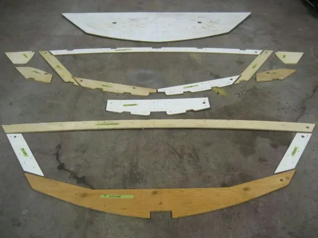
Since there was a possibility of building more than one boat in the future, we produced a set of frame templates to impr
Since there was a possibility of building more than one boat in the future, we produced a set of frame templates to improve construction accuracy and save layout and production time on subsequent boat builds. Click here to learn more about the frame templates.
18 May 2025
Latest update : We've recovered from our cardiac issues and getting back into our truck camping and boating trips
Latest update : We've recovered from our cardiac issues and getting back into our truck camping and boating trips. We have also been commissioned to build a Glen-L Mist Miss for a Glen-L boatbuilder from Kentucky, USA. His boat build progress is posted on the Glen-L Boatbuilder Forum : Dave's Mist Miss Build I hope you have enjoyed viewing the Hot Rod Project. If you have had any problems using this web site or have any comments or suggestions for improvement, send us an email. Click the Left Menu tabs to see more boats and videos : Video Directory (Glen-L Boat Videos and Photo Albums) Glen-L Gatherings (Glen-L Boatbuilder's Gathering Photo Albums and Videos) Other Boatbuilders (Bruce Dow's Glen-L Monaco and Bruce Taber's custom inboard runabout) If you can spare the time, the folks at the Boatbuilding Web Ring would appreciate it if you would Rate this Site. Thanks ! Sign our Guestbook : If you have any comments or questions about the website, boatbuilding in general or wish to tell us where you're from and what you are building, please Sign our Guestbook. Thank You !
boatbuildlog.com
Glen-L Hot Rod
97 entries,
369 photographs,
written down as the work was done.
The words and photographs in this log belong to Paul Kane.