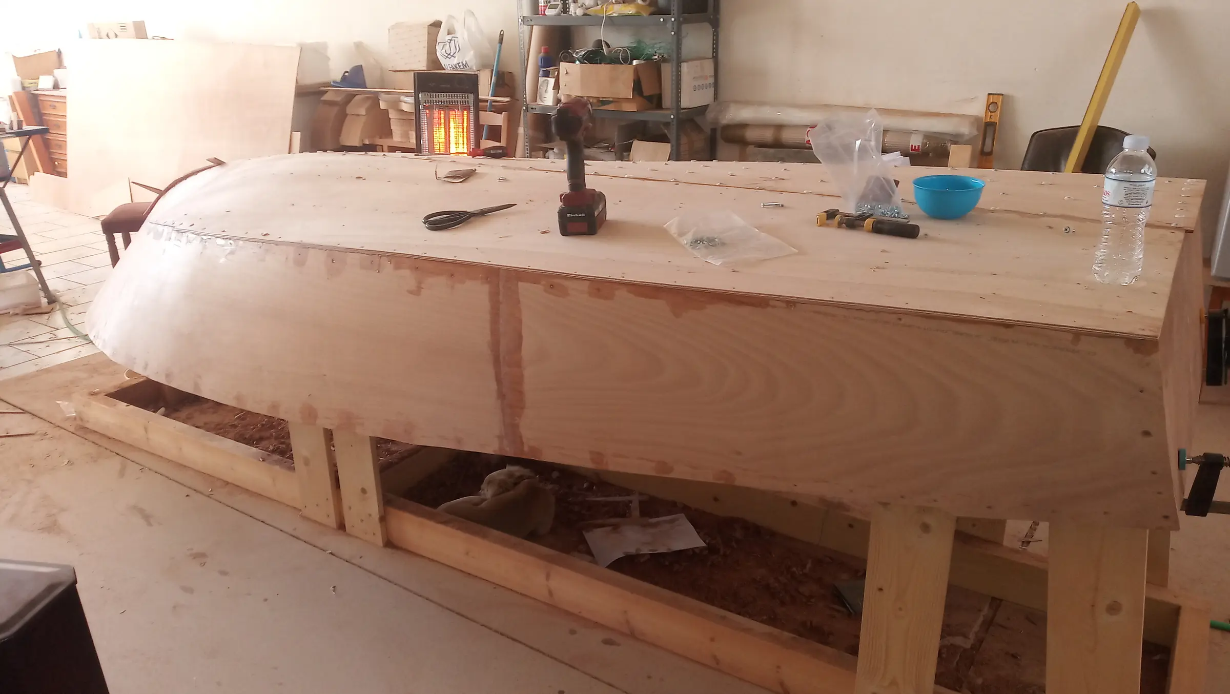
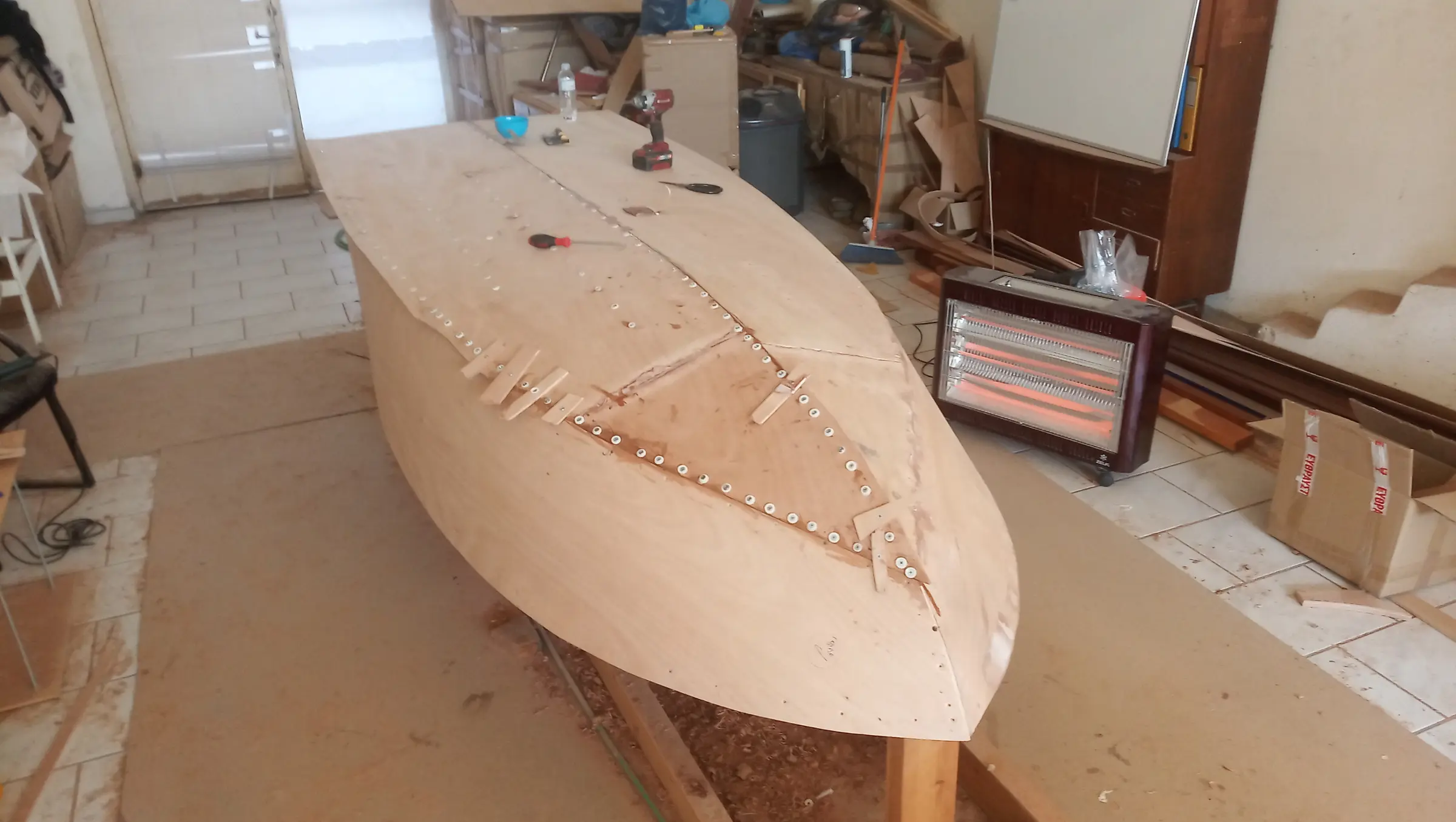
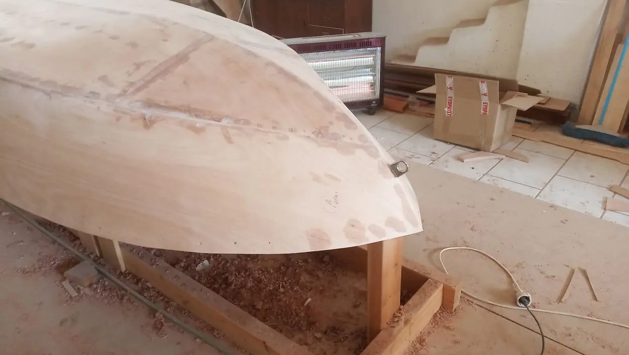
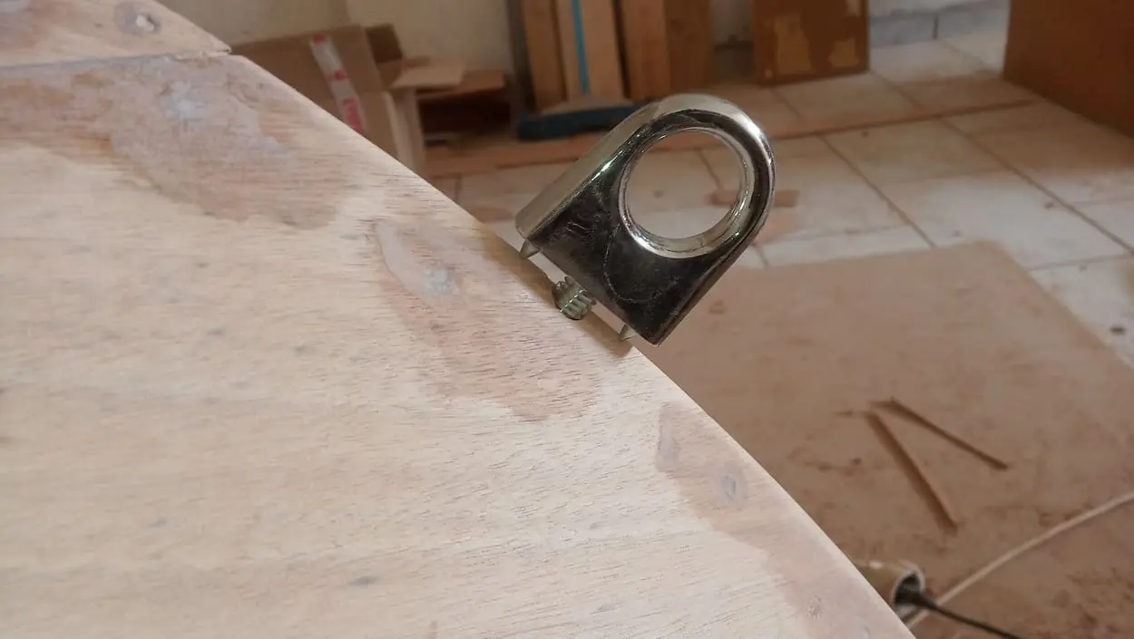
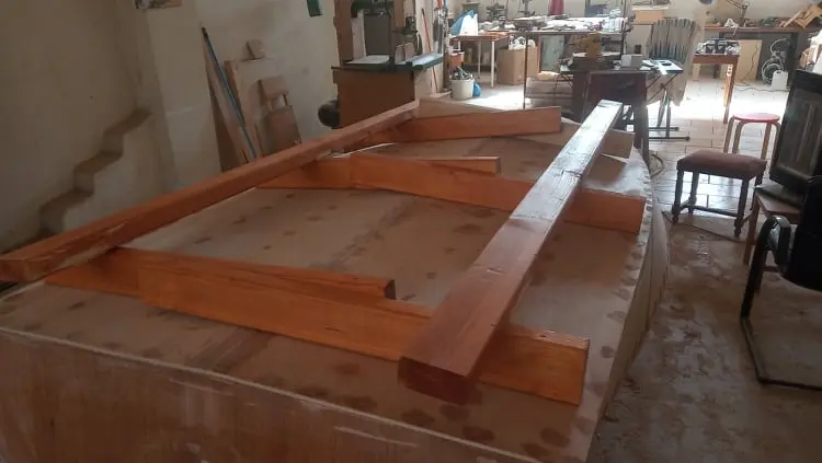
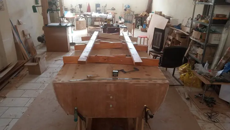
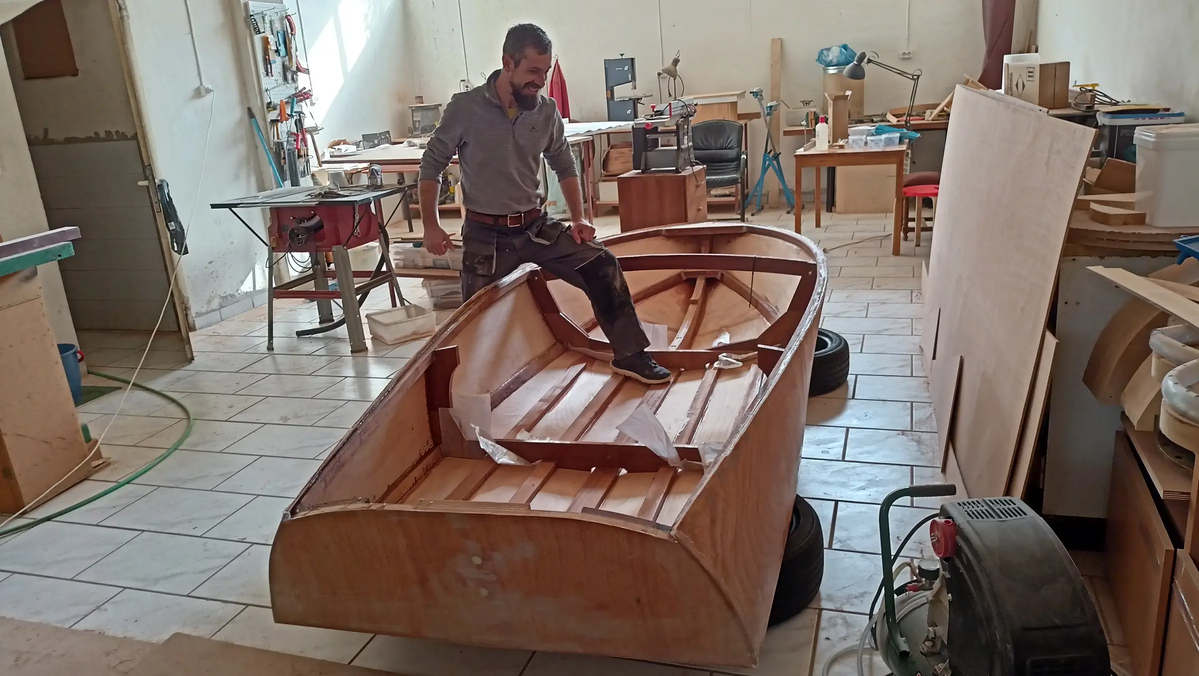
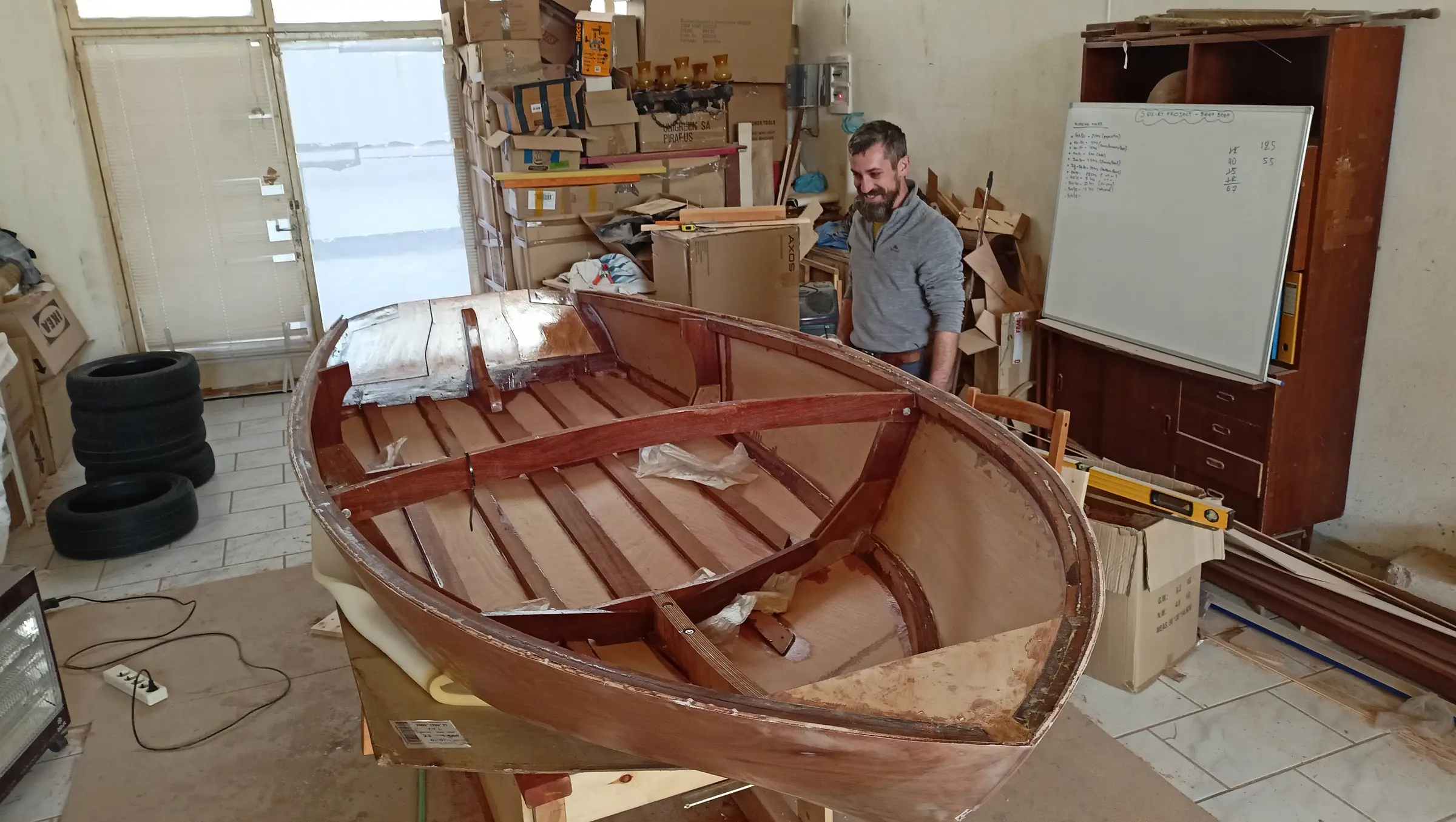
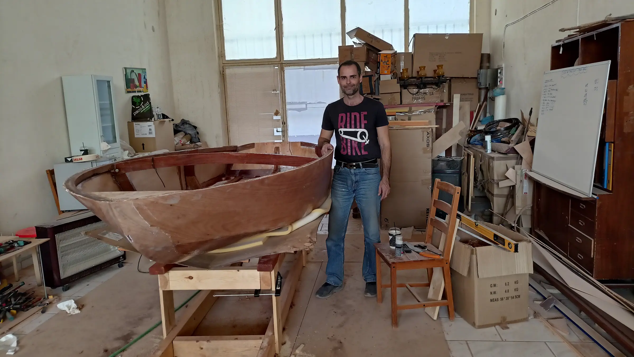
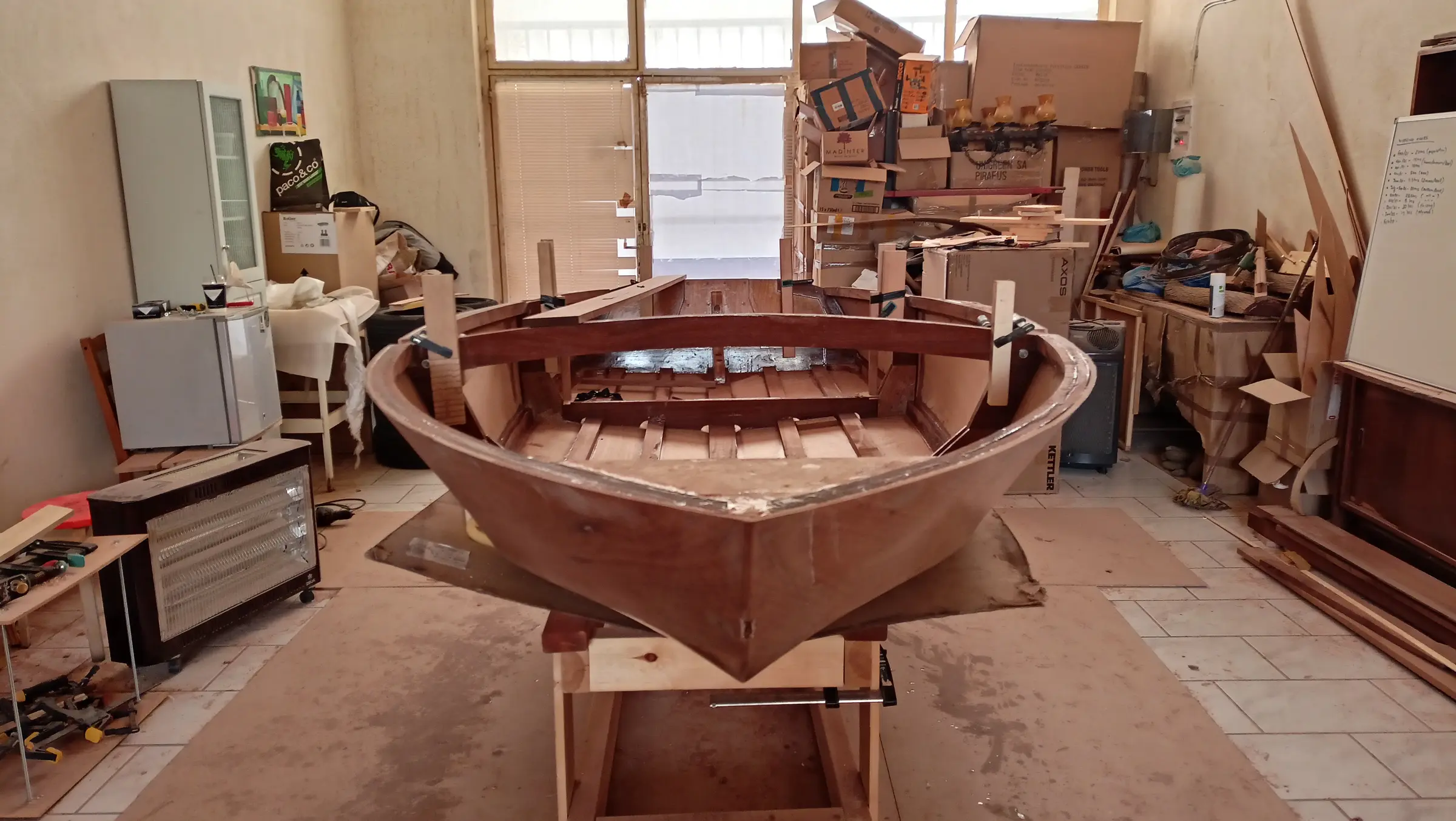
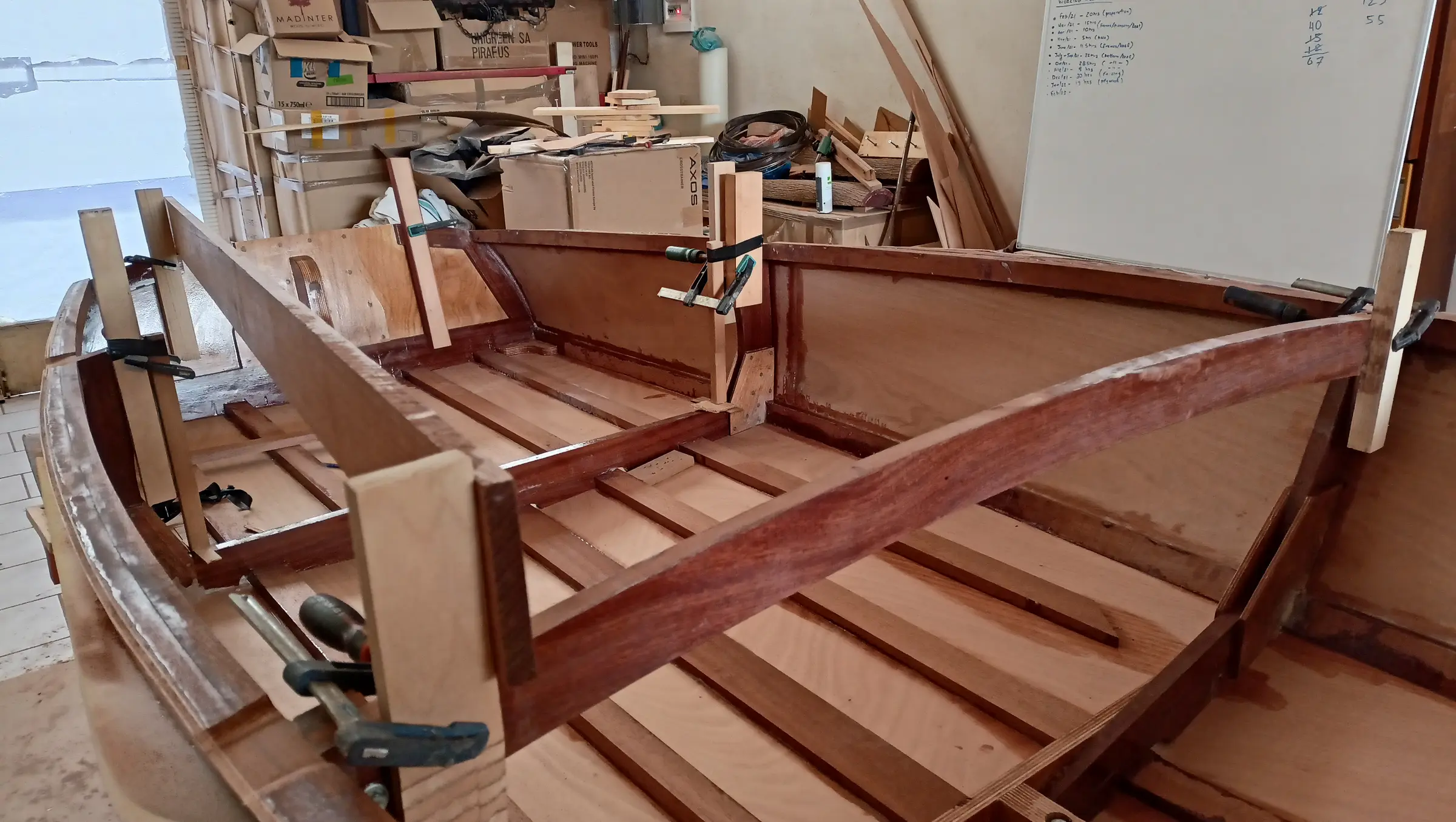
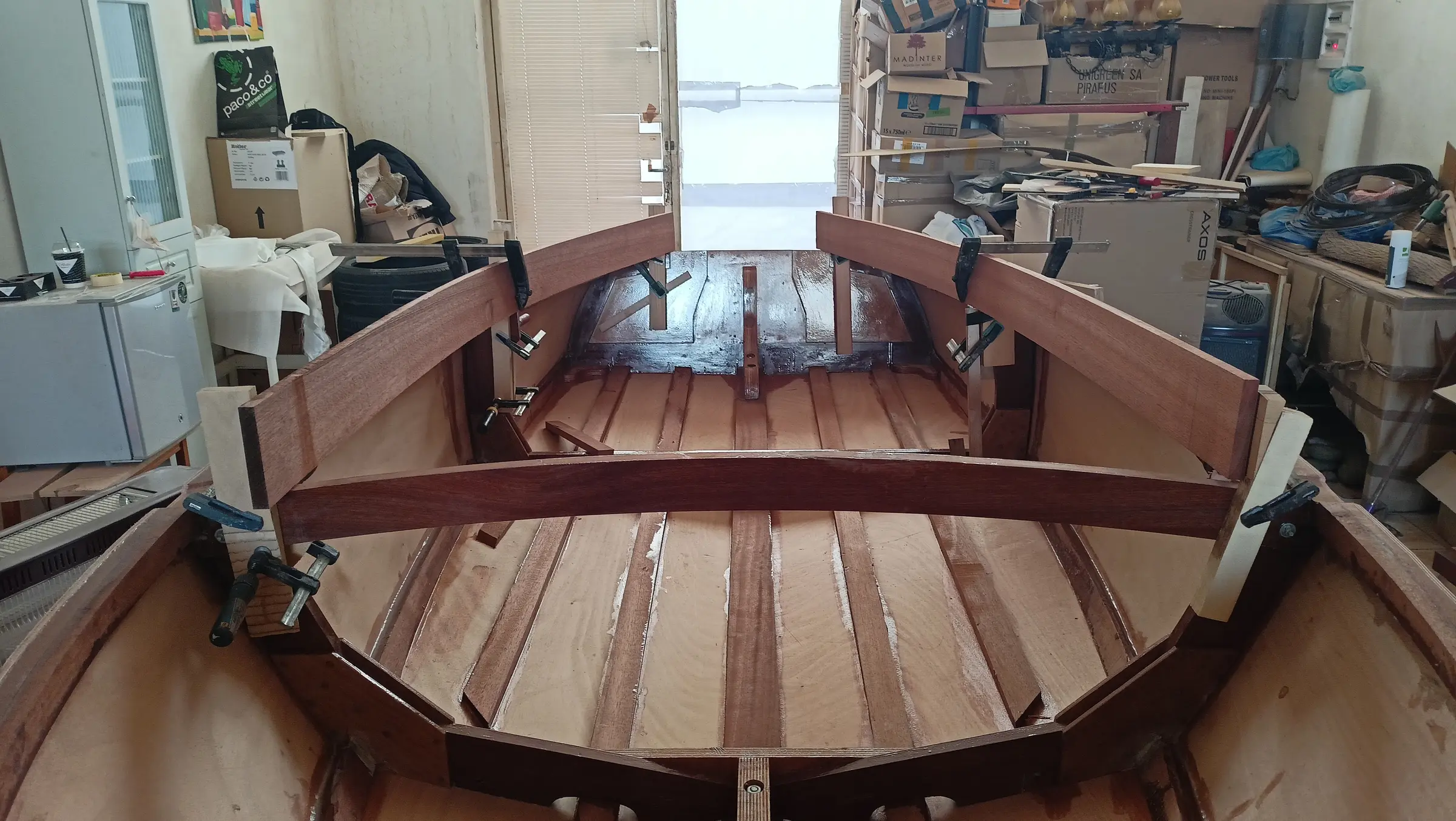
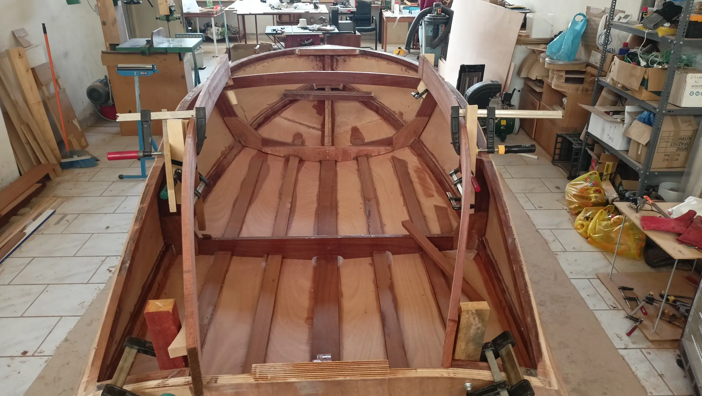
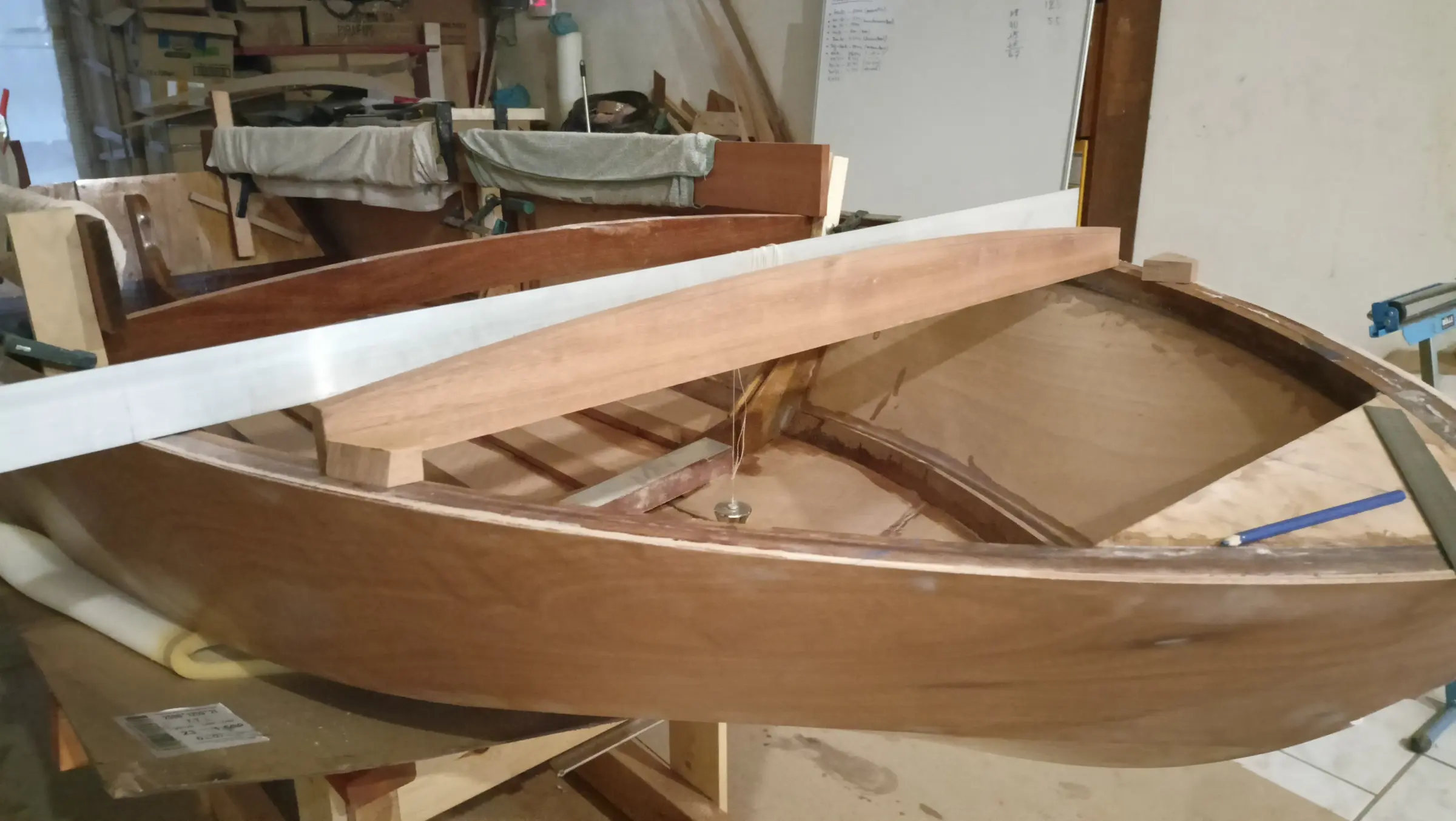
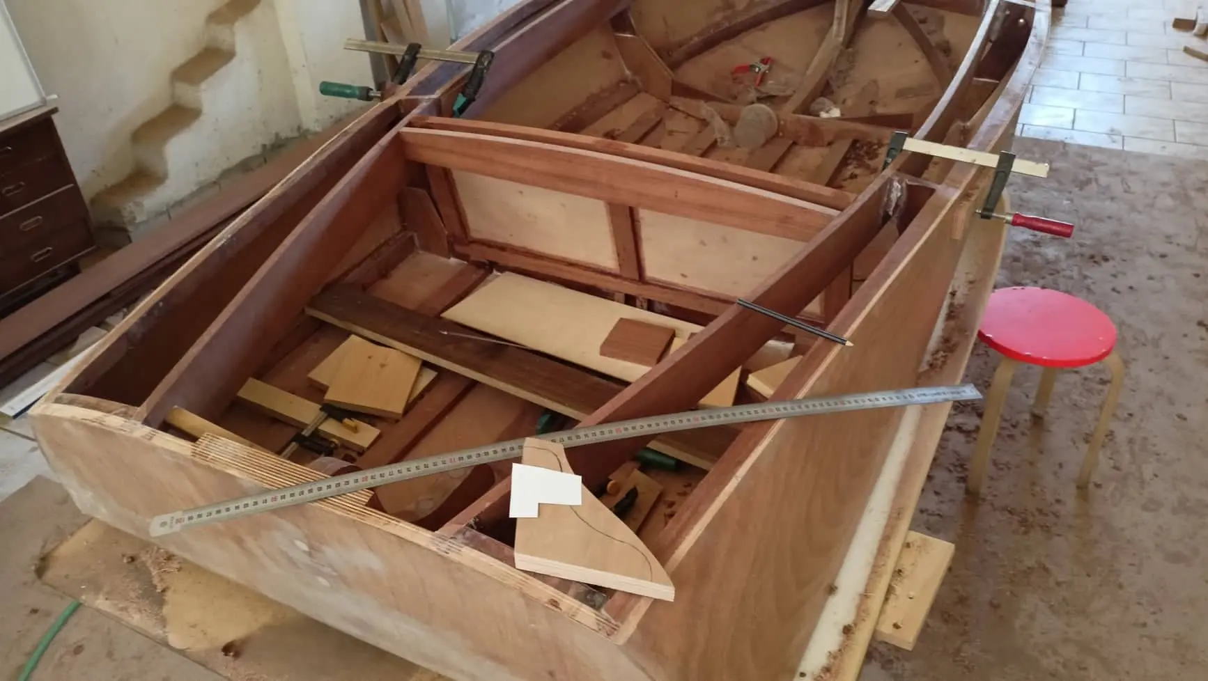
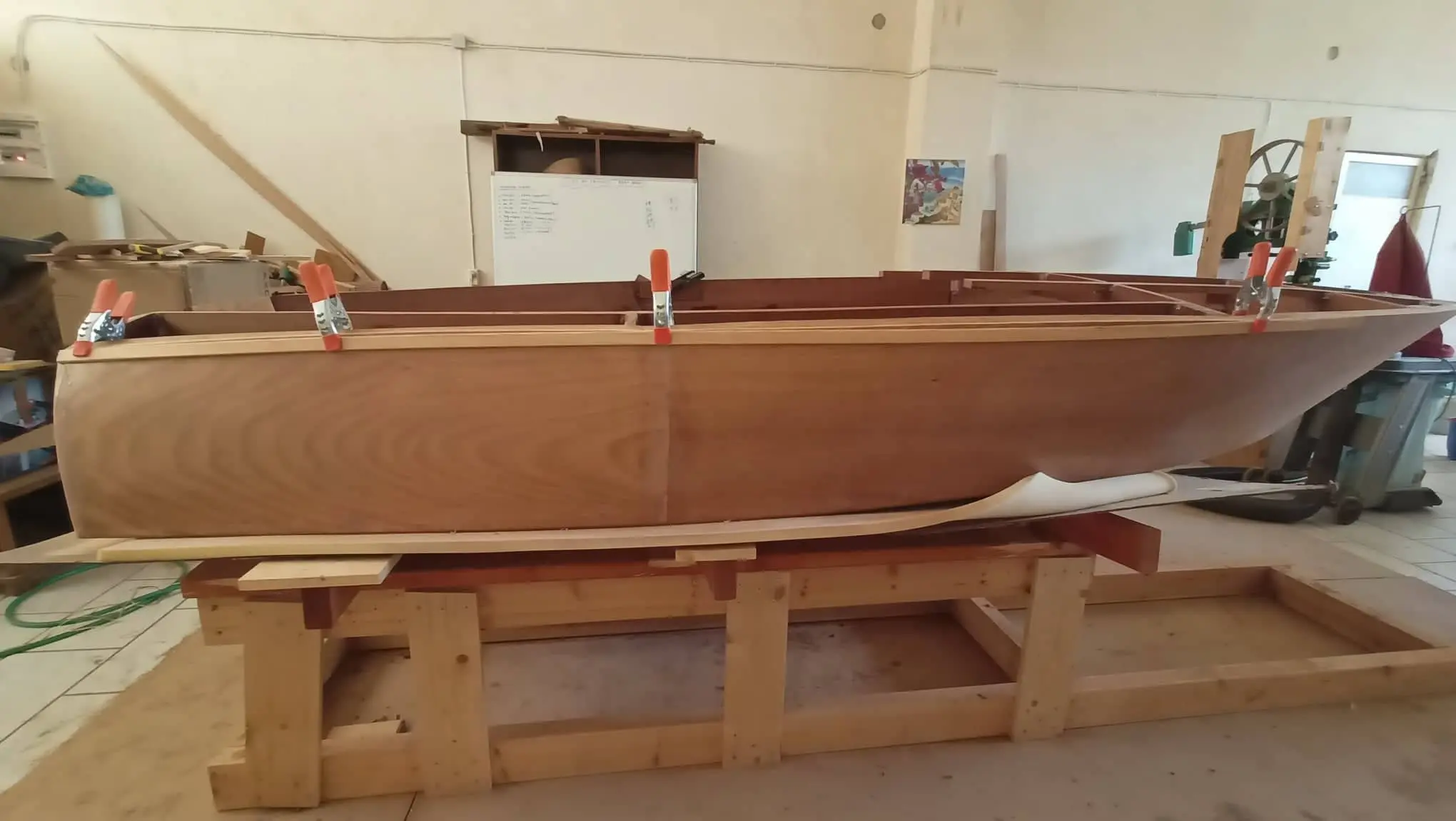
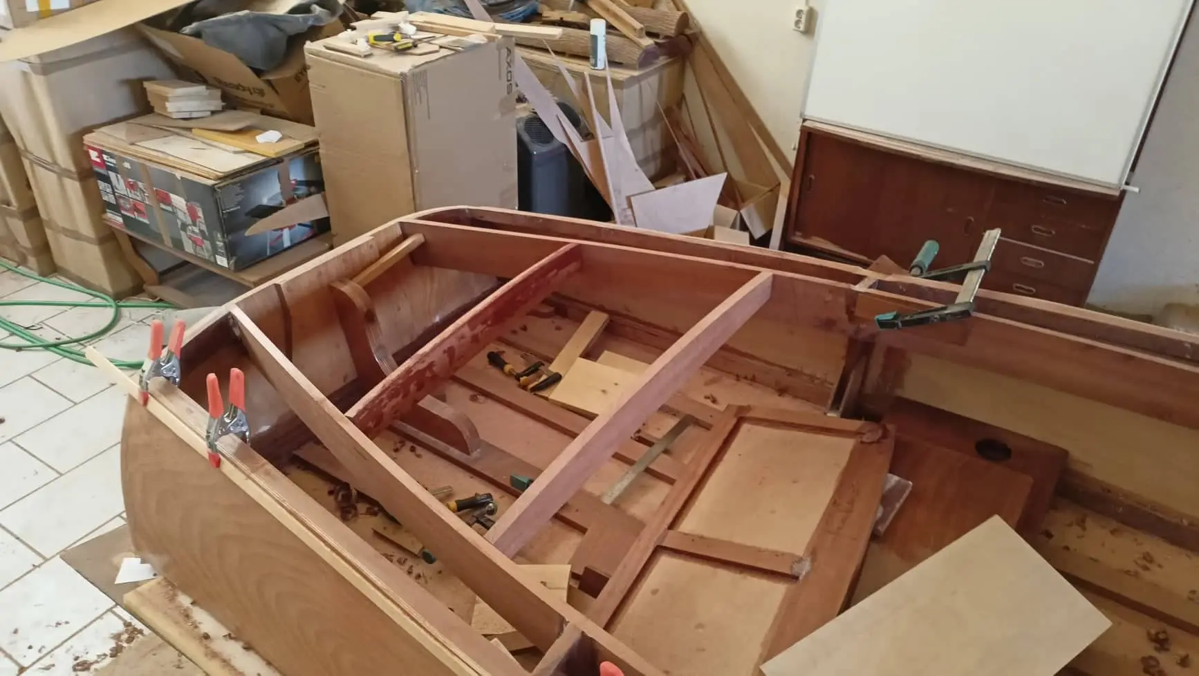
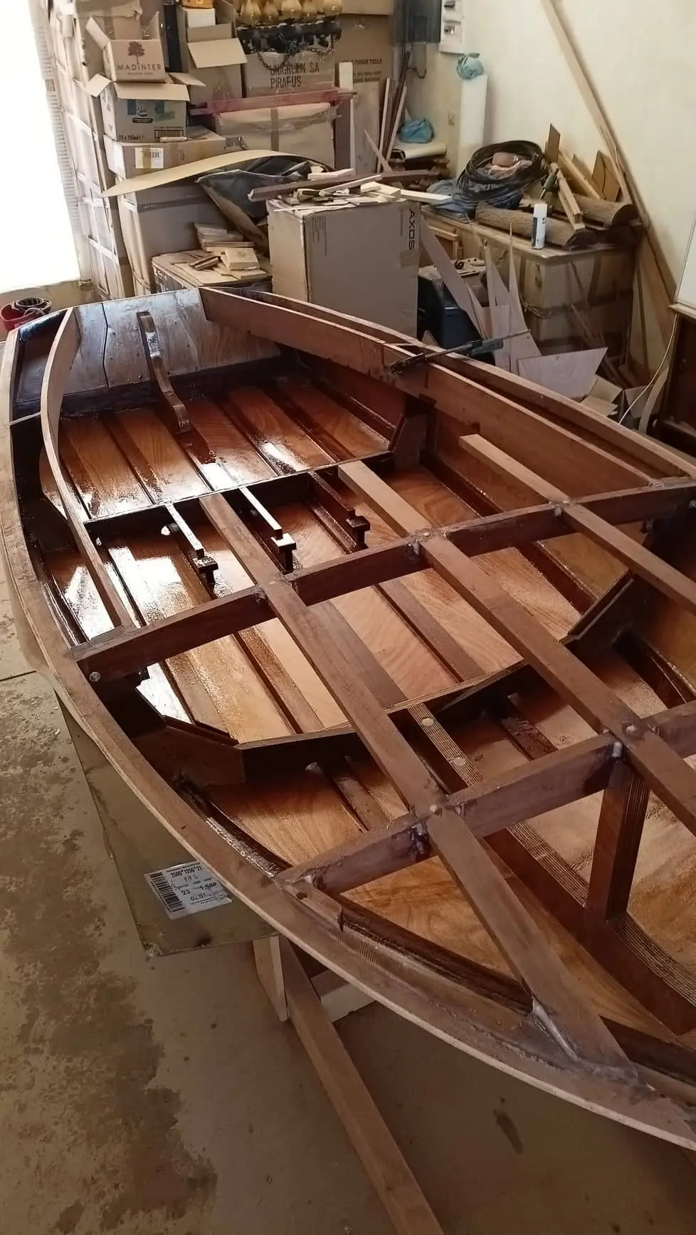
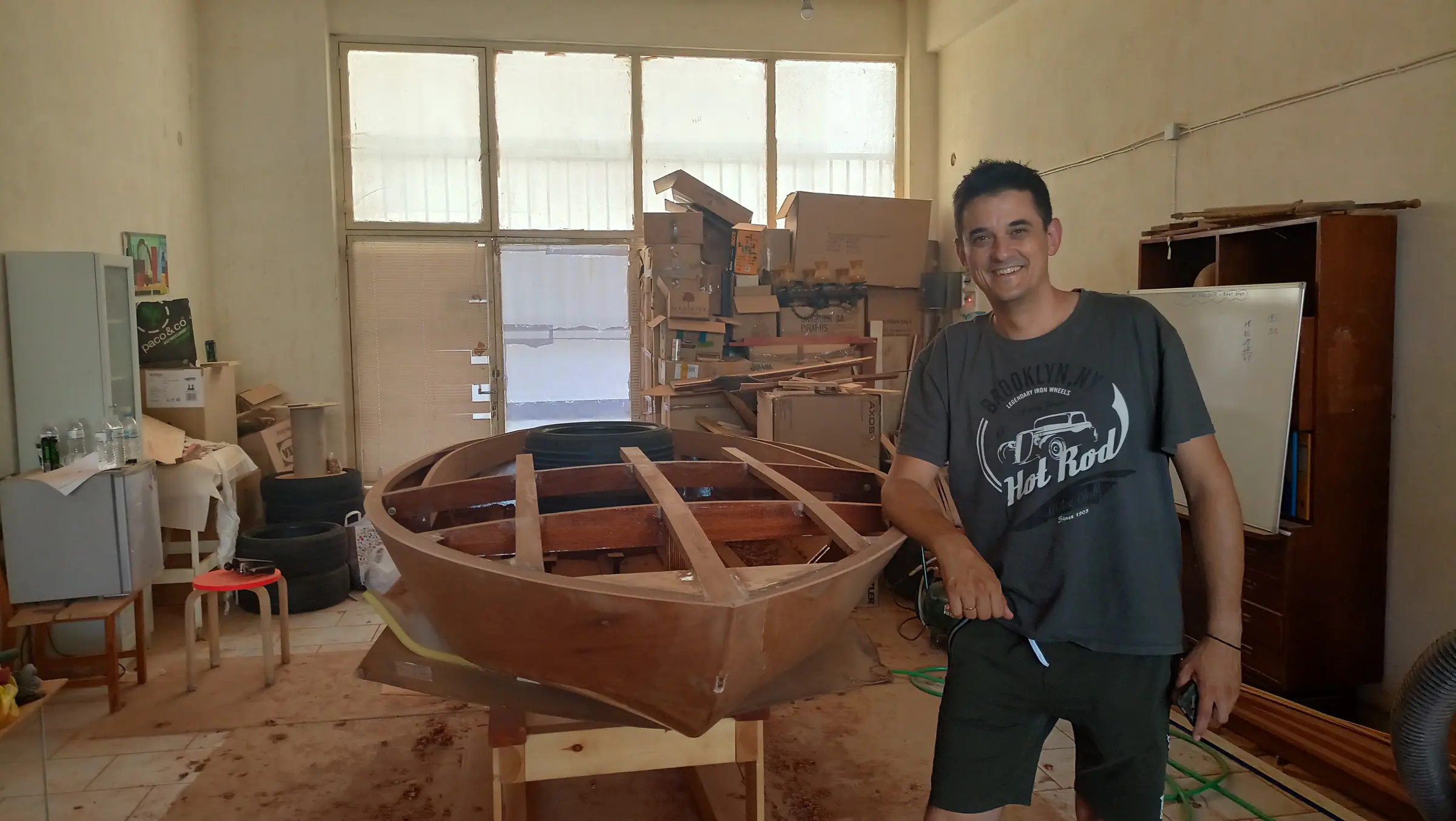
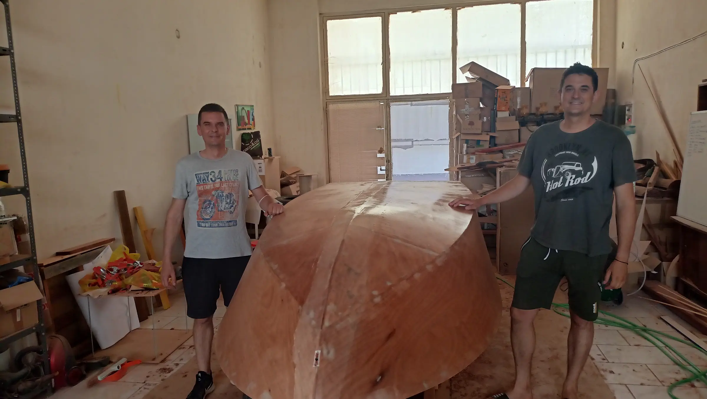
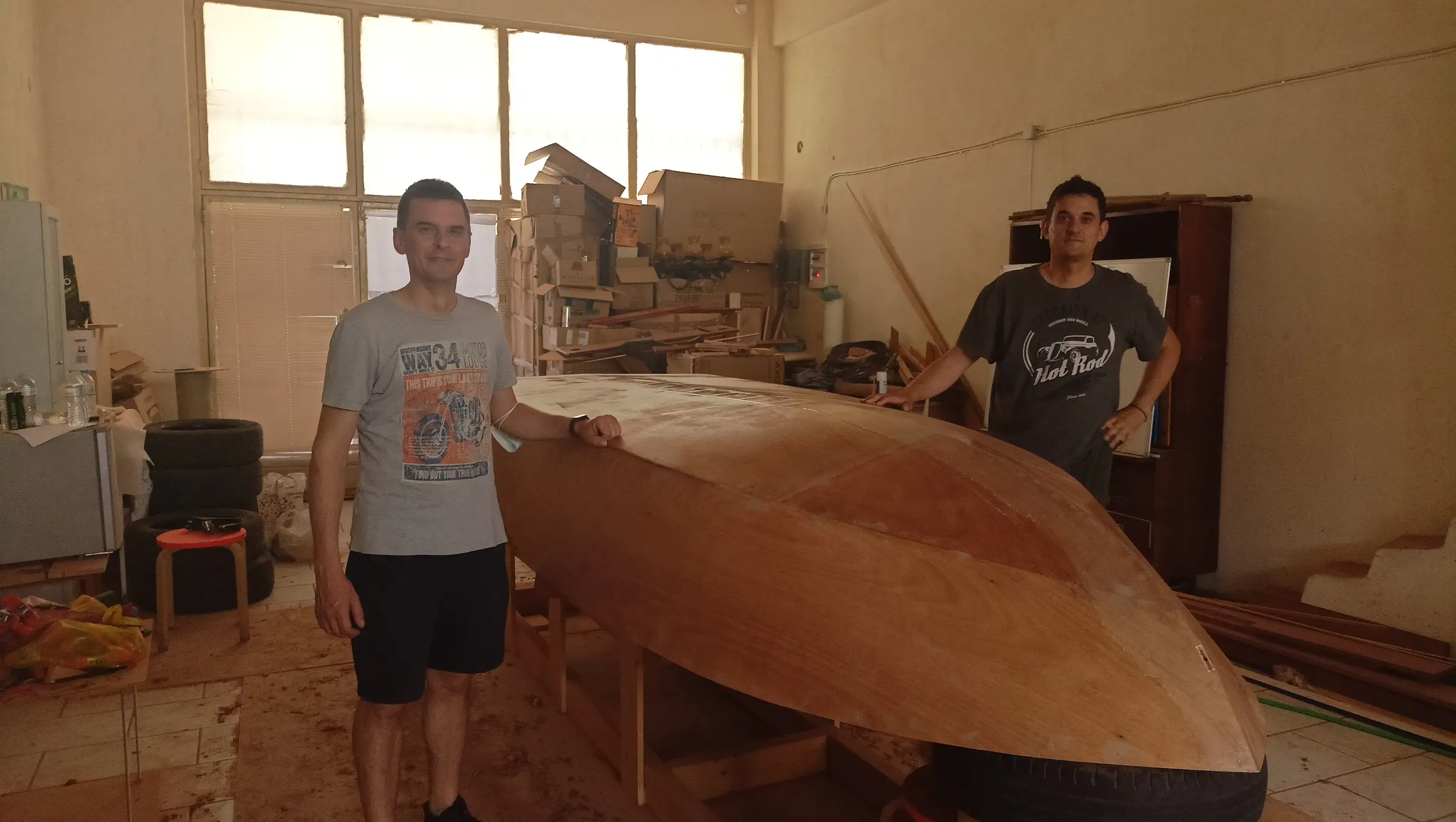
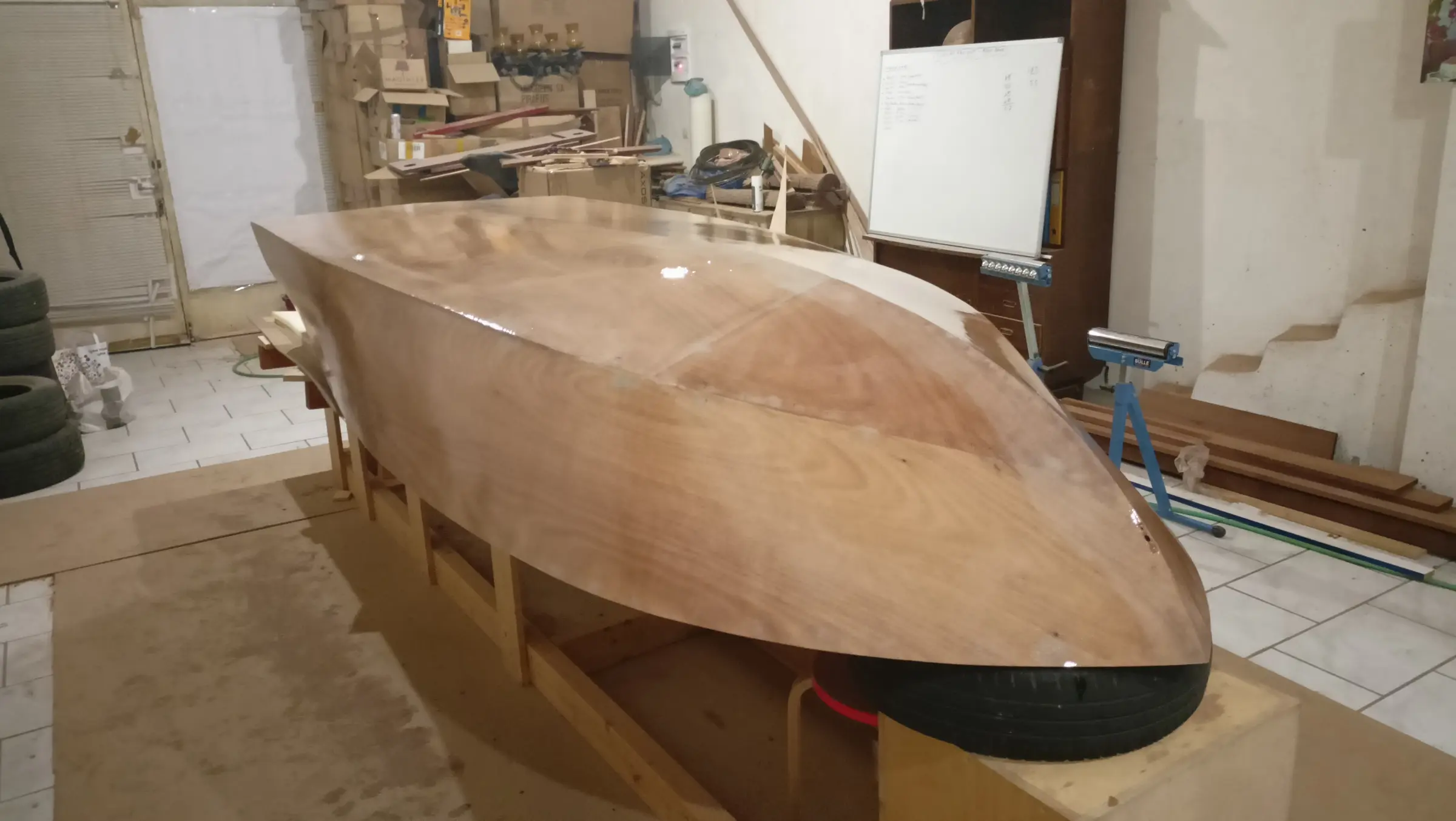
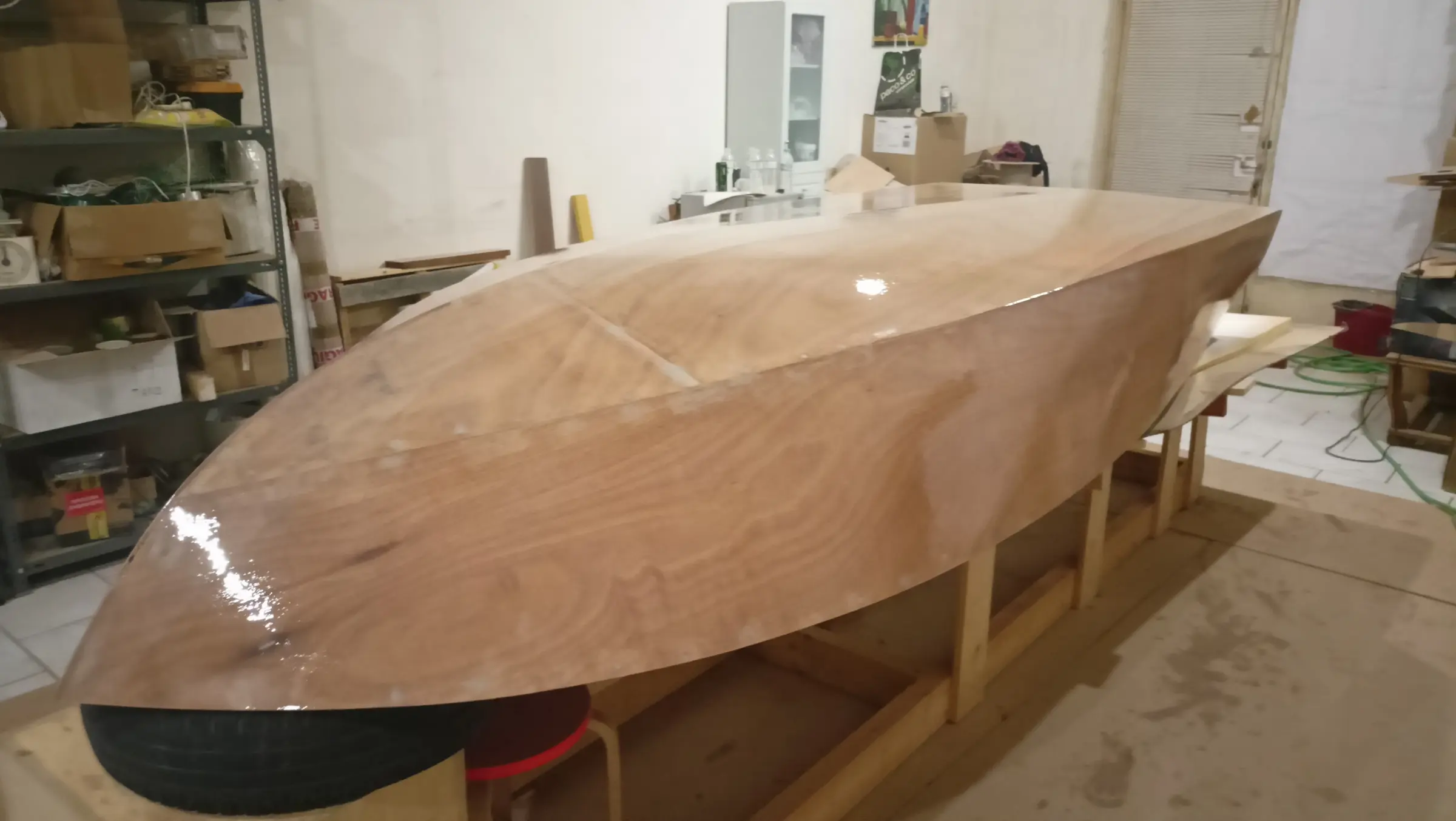
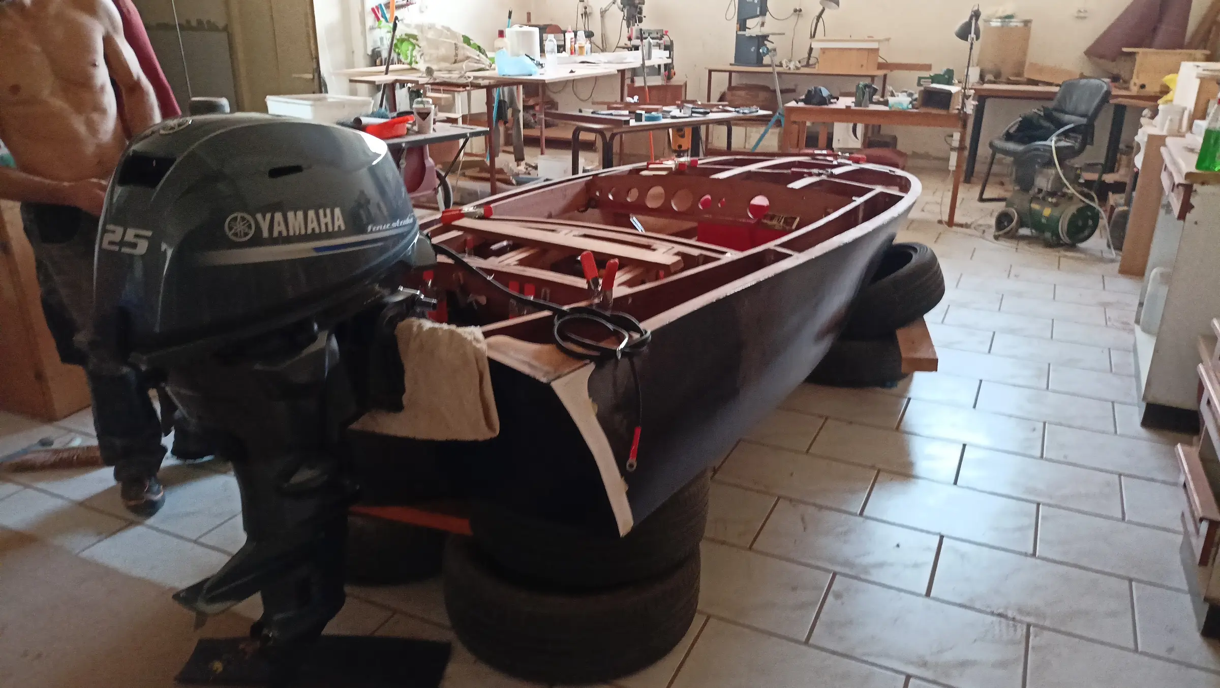
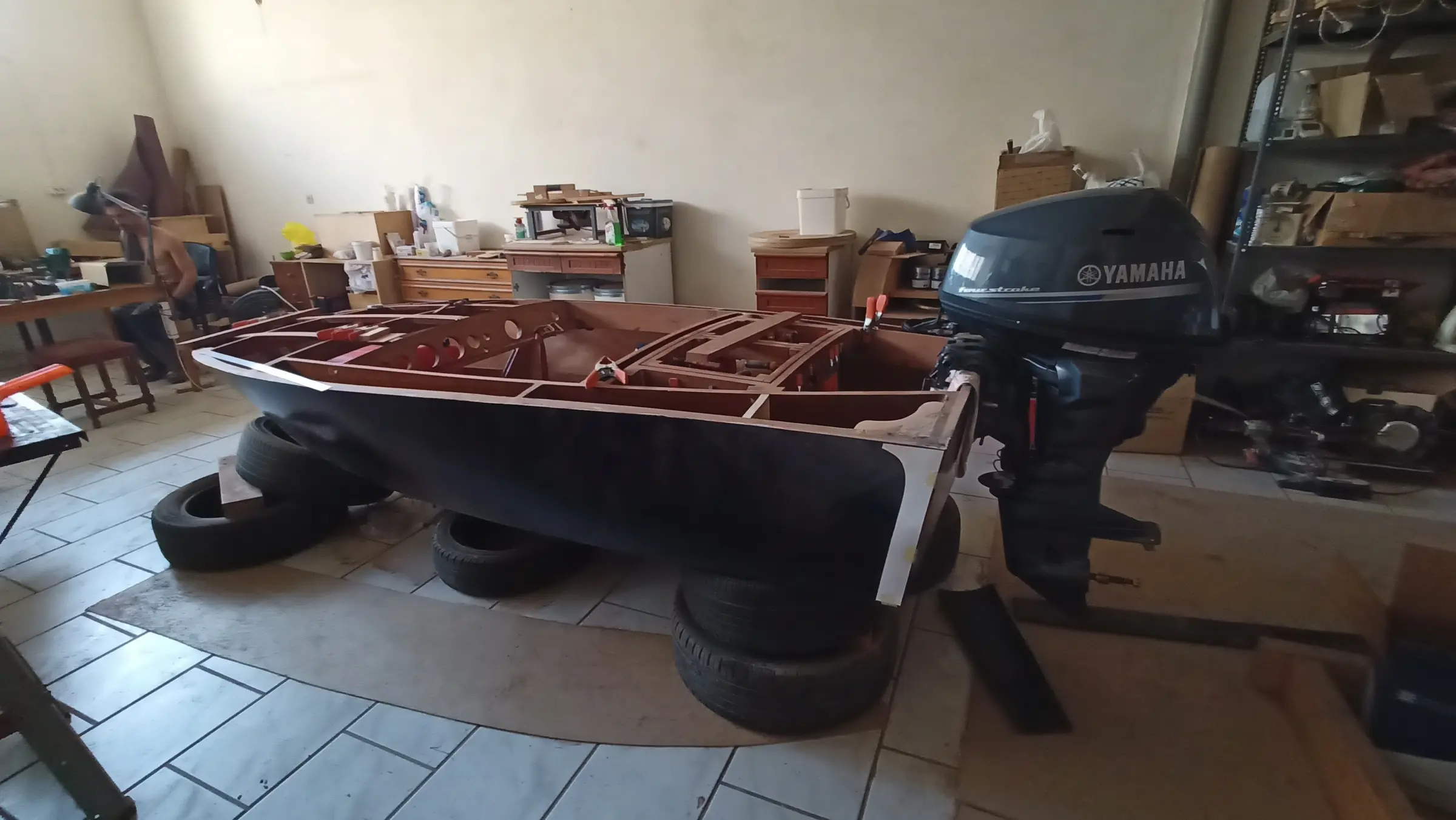
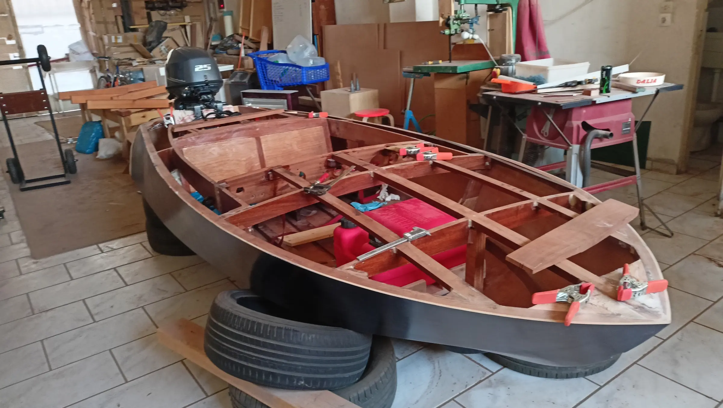
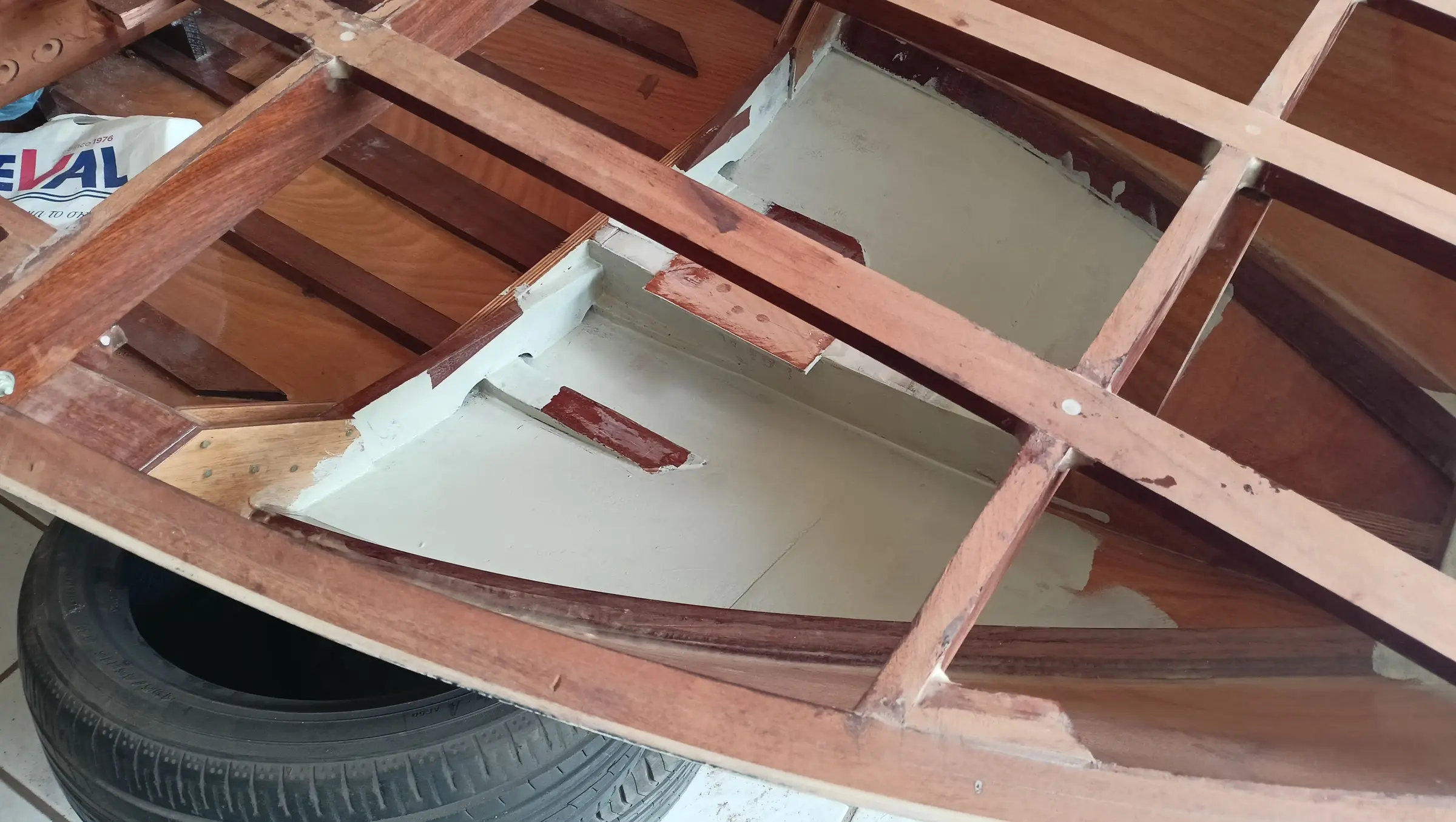
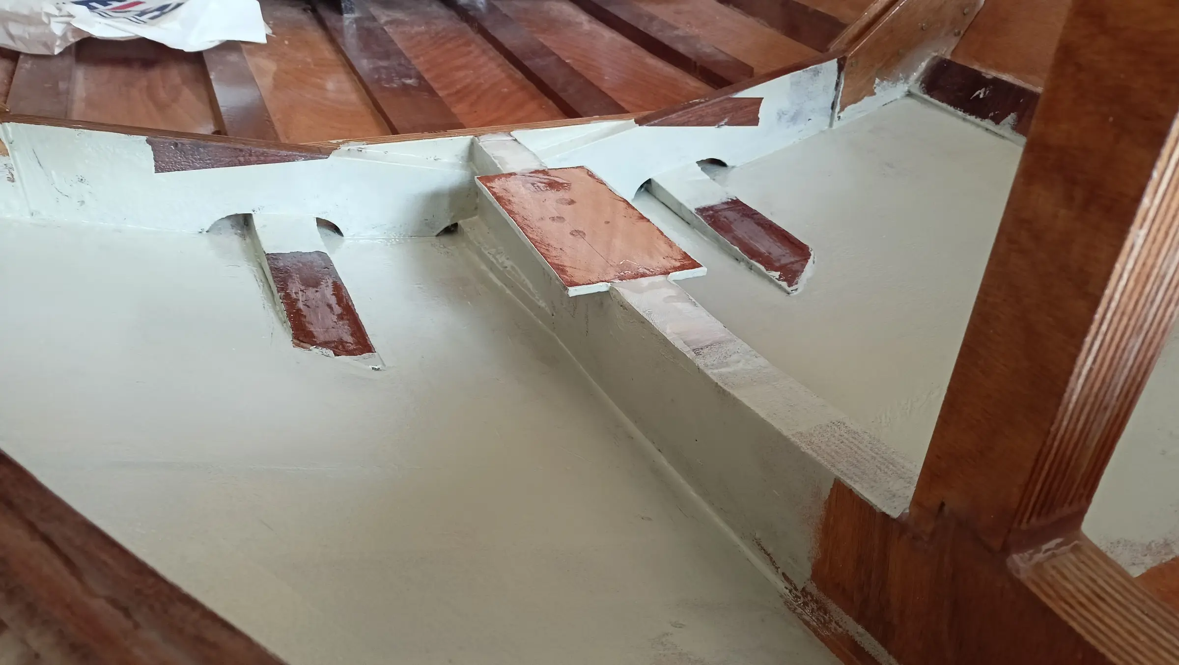
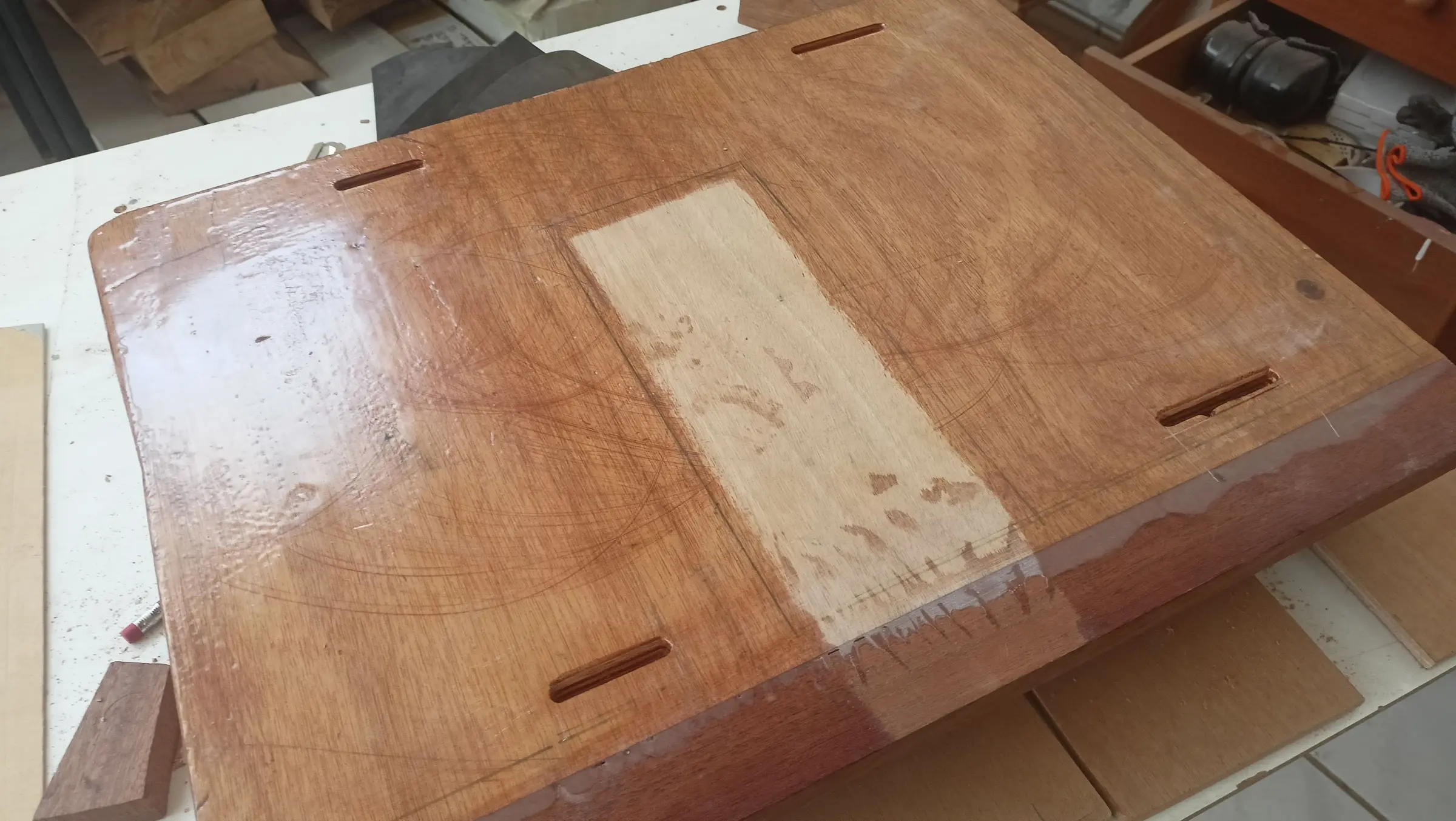
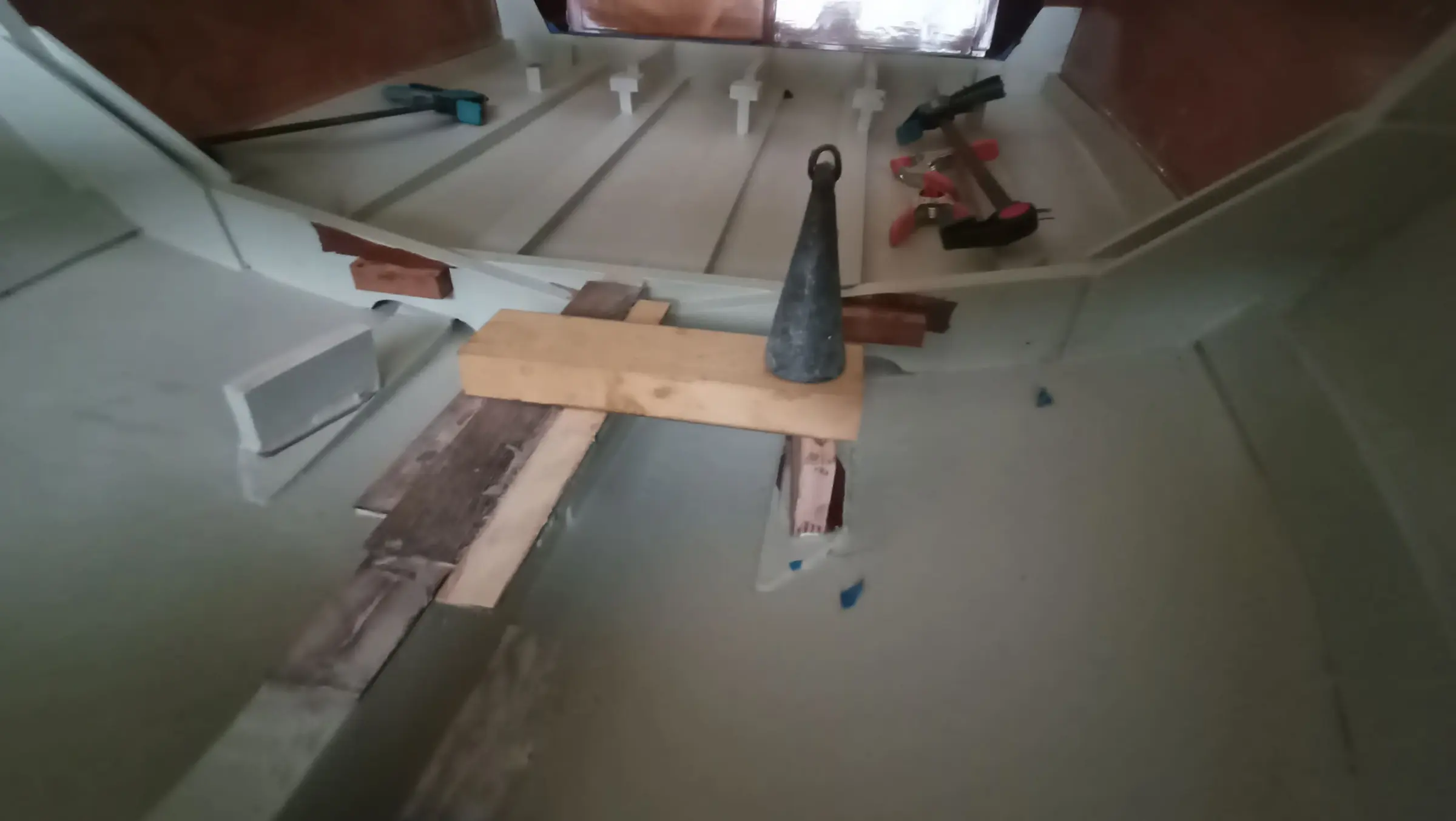
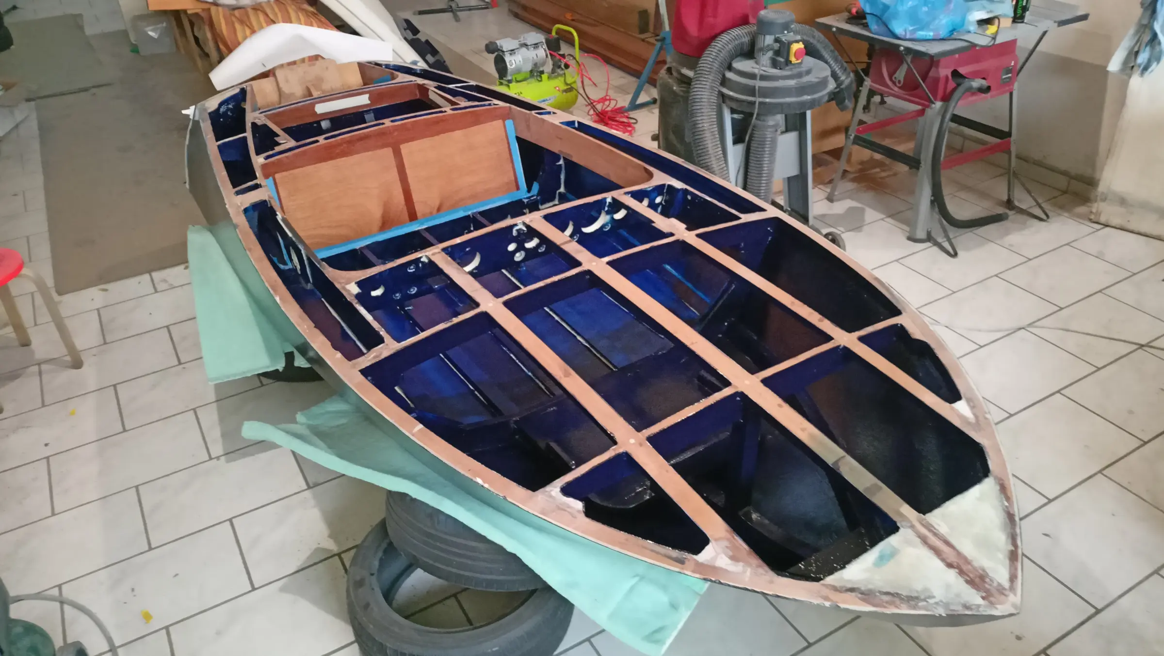
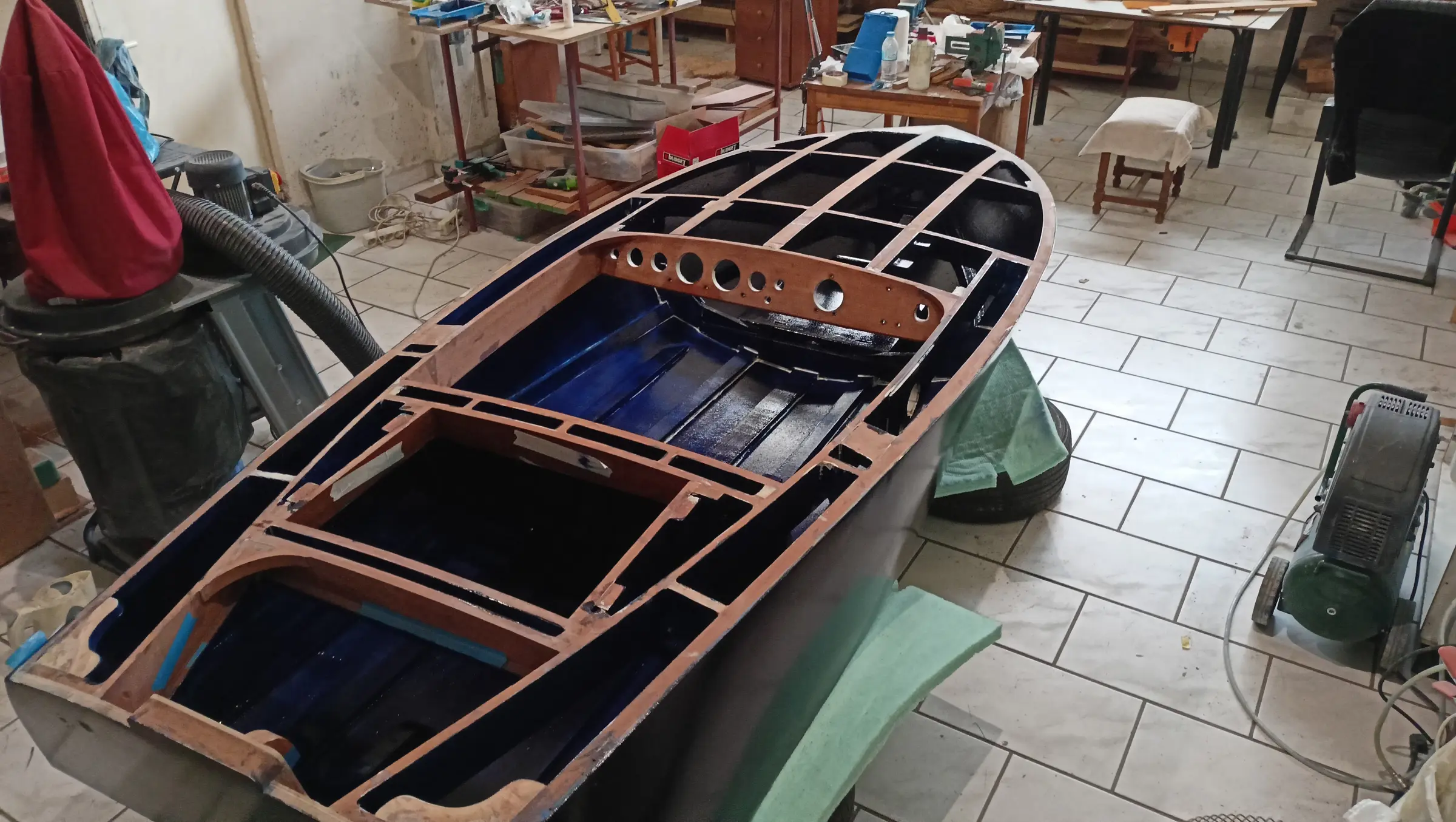
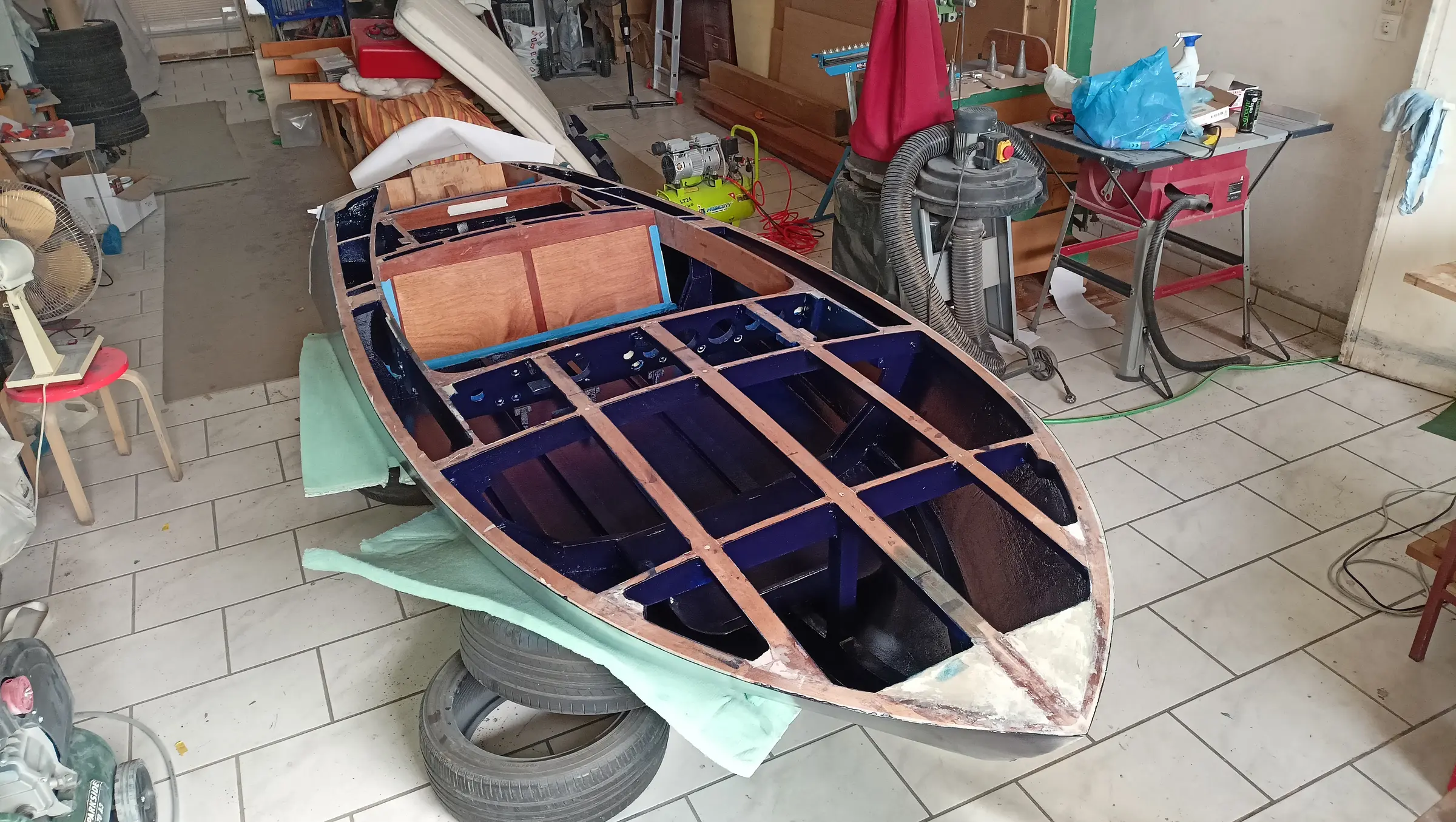
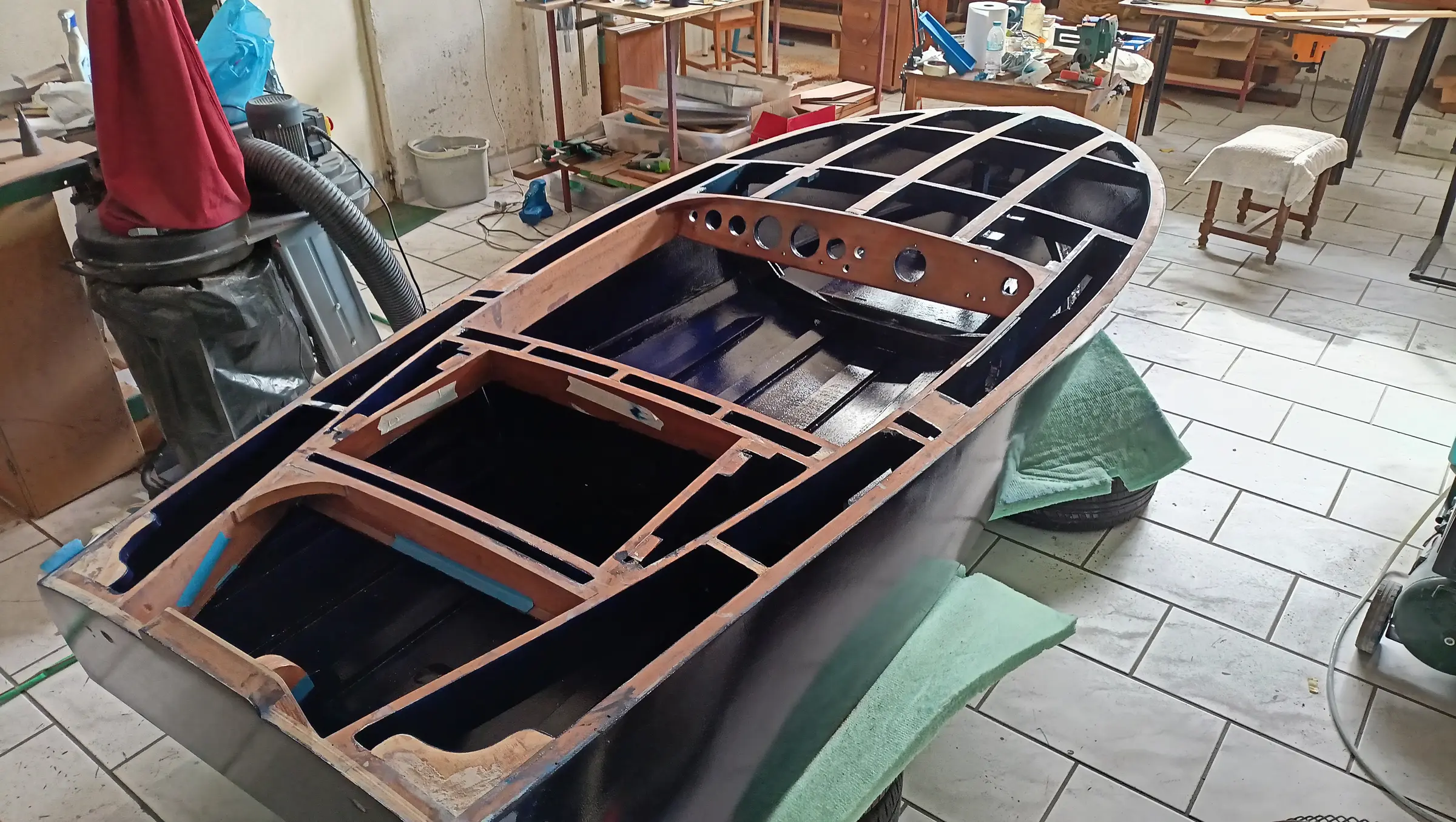
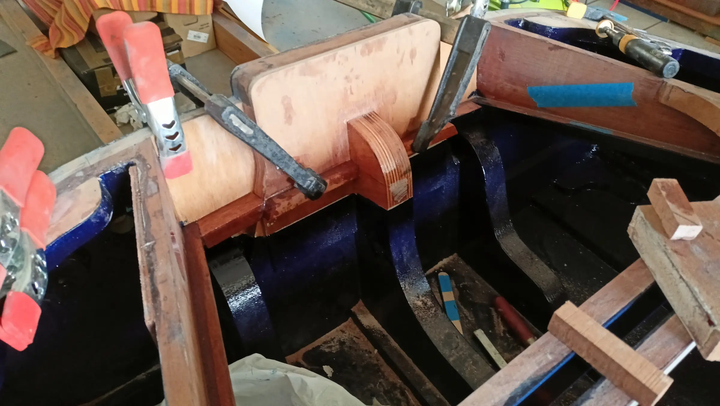
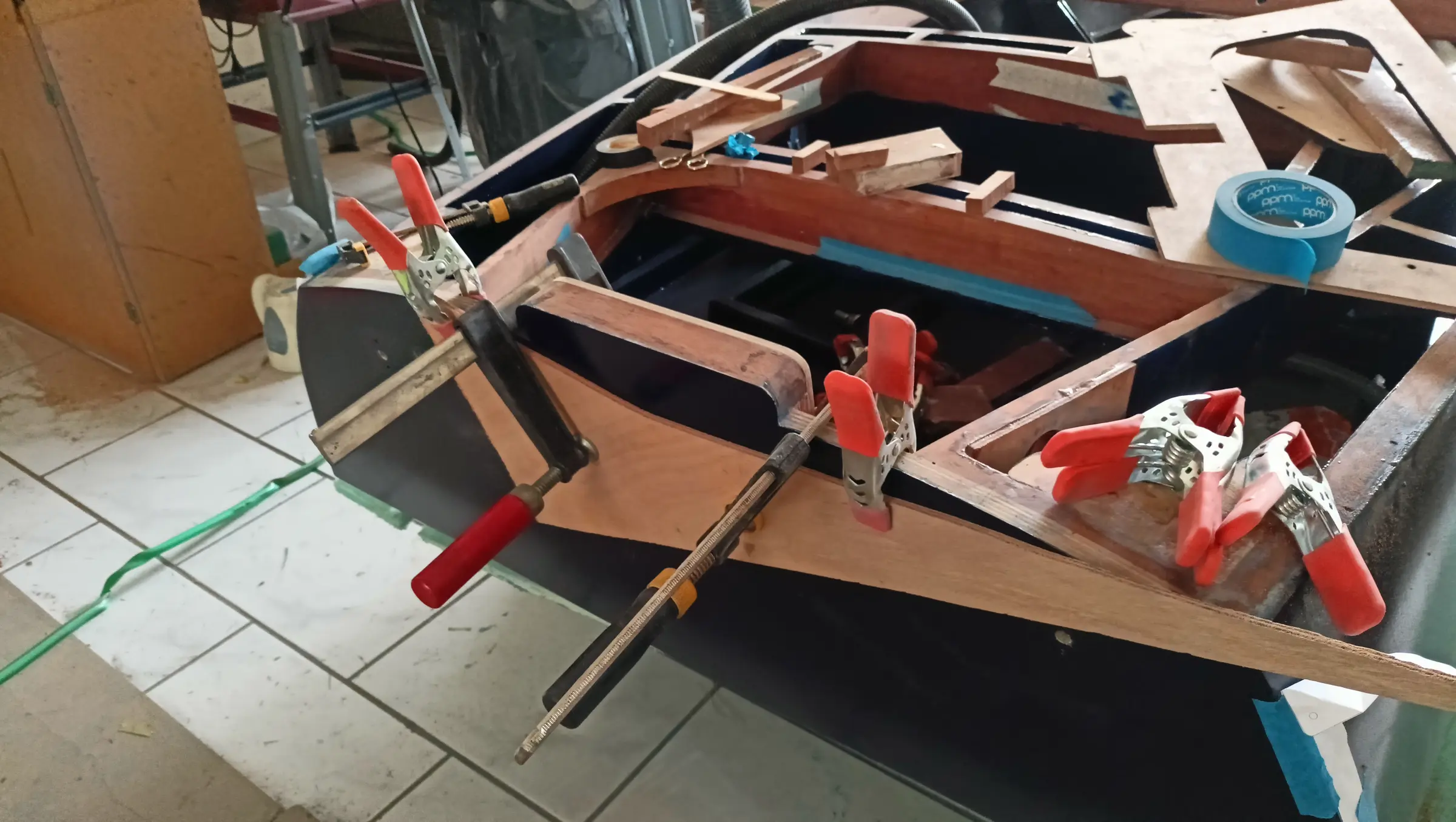
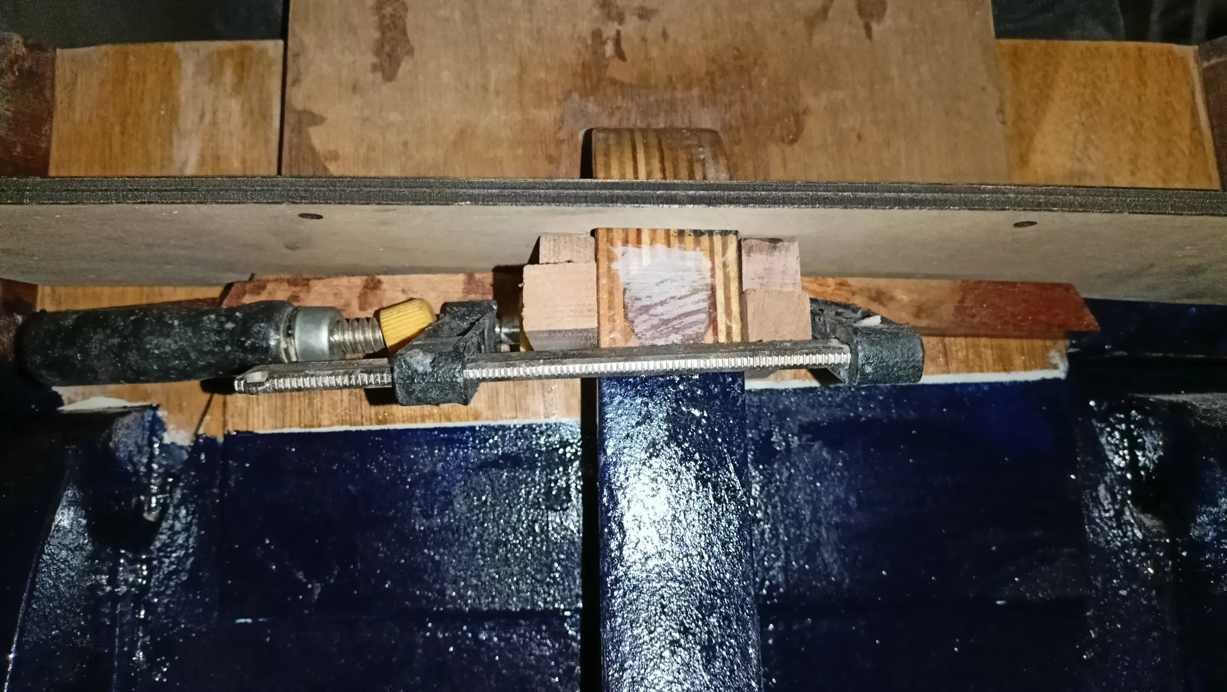
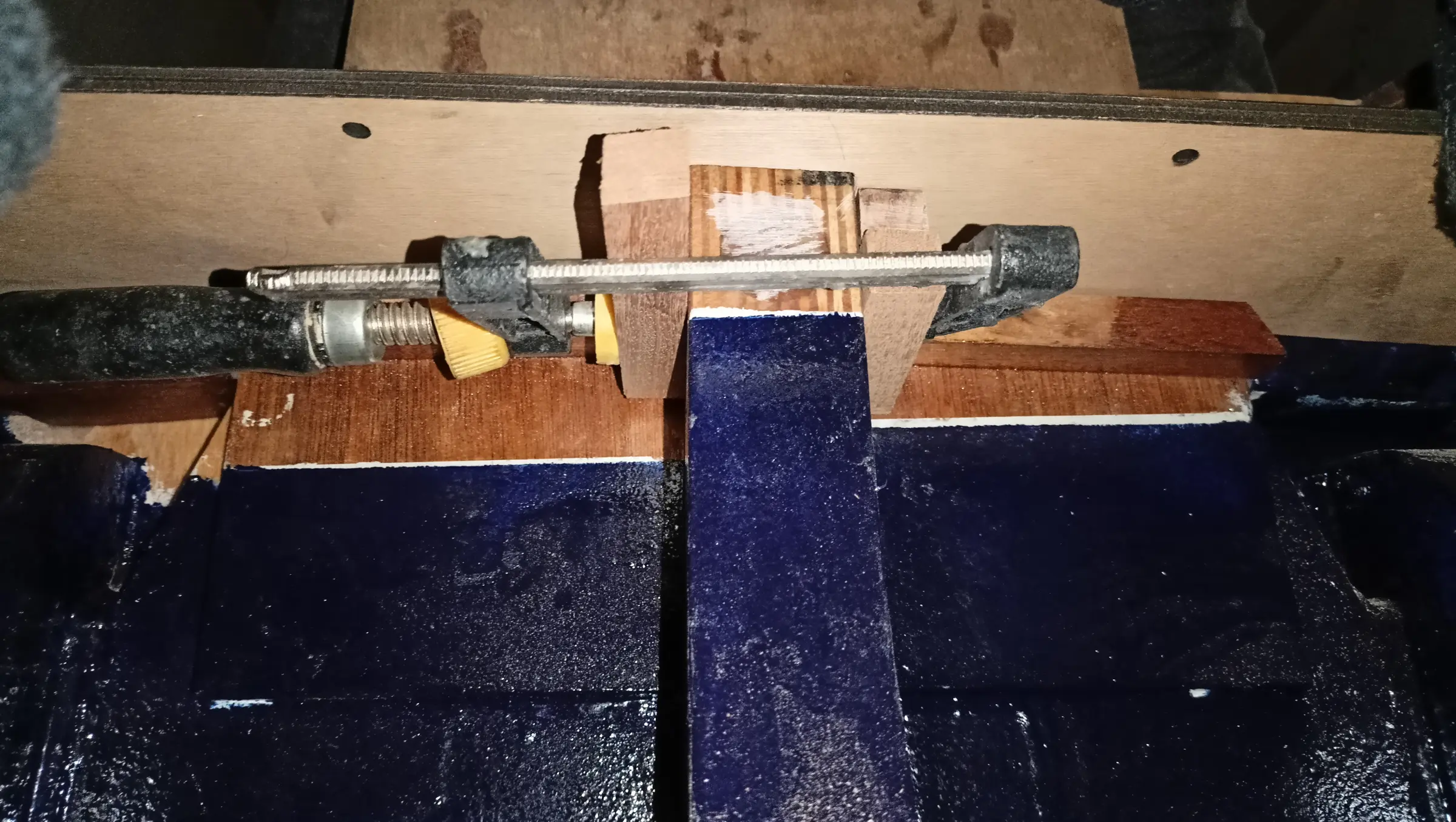
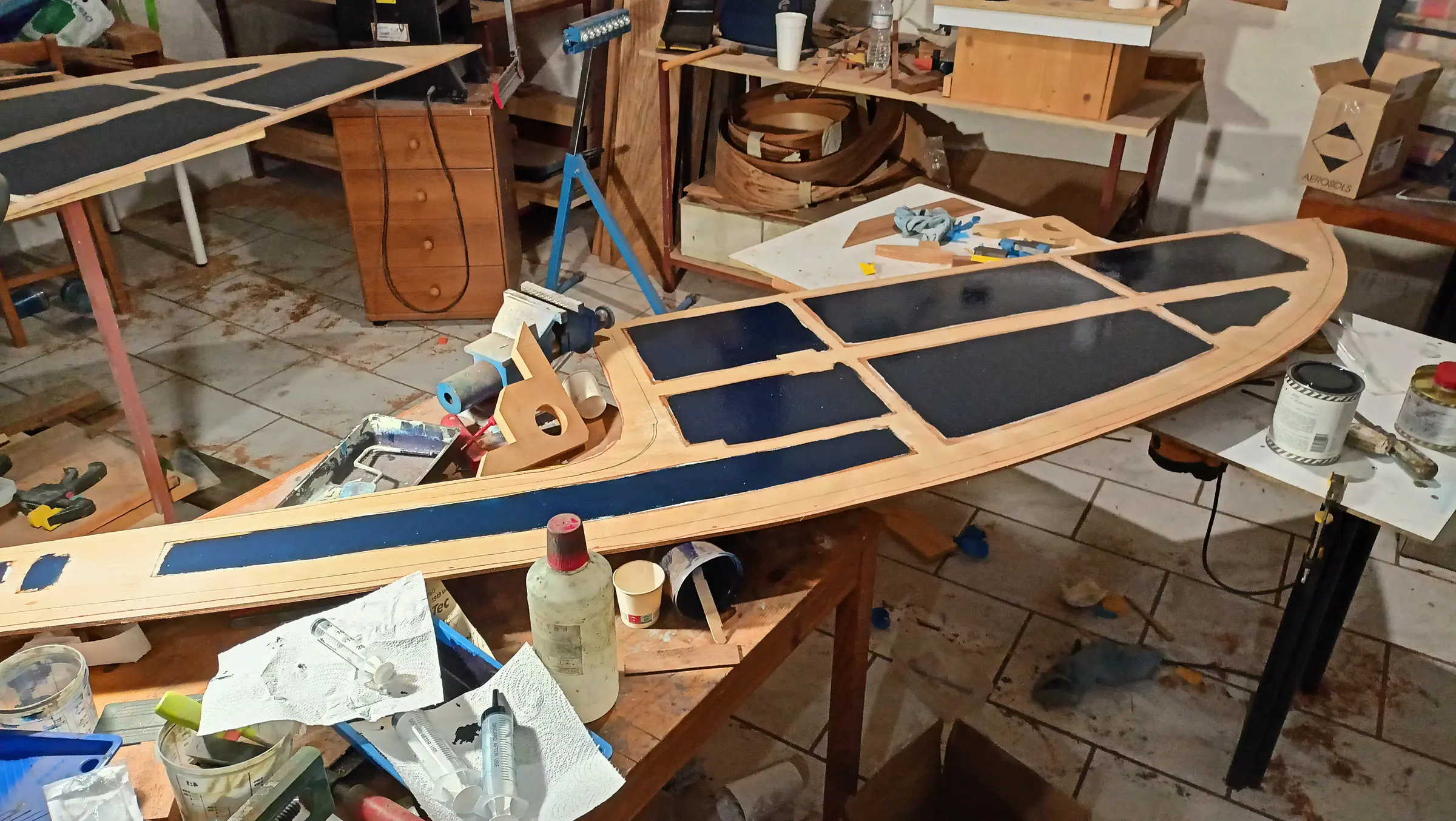
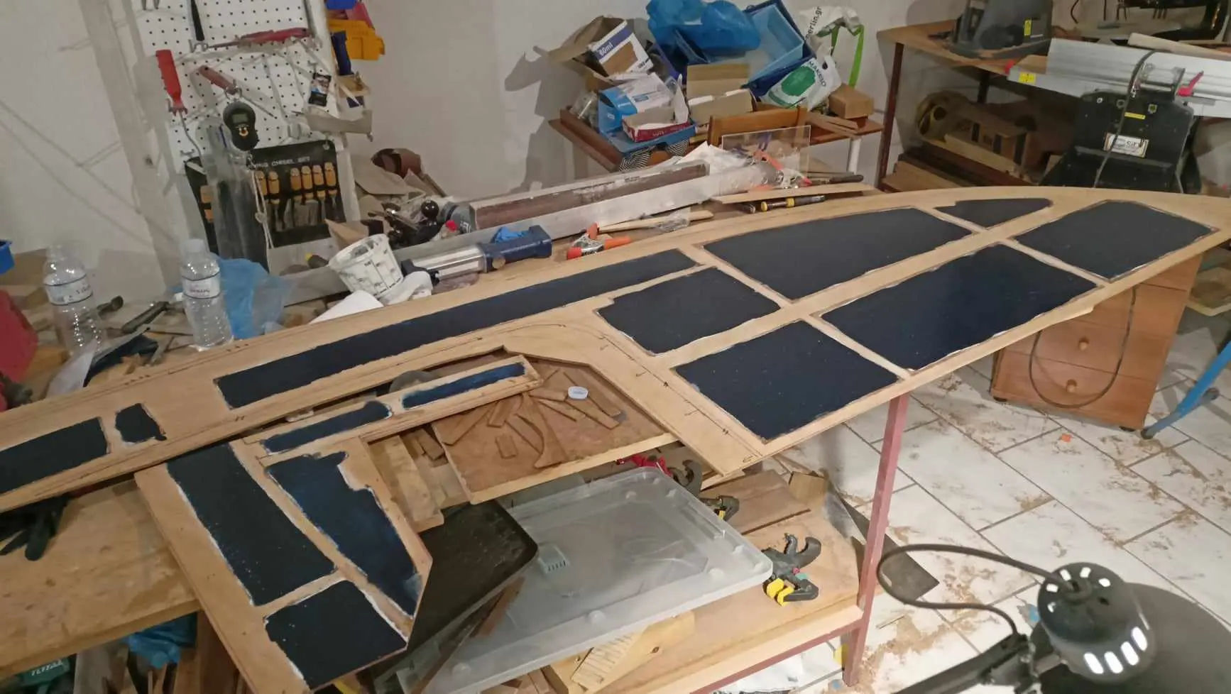
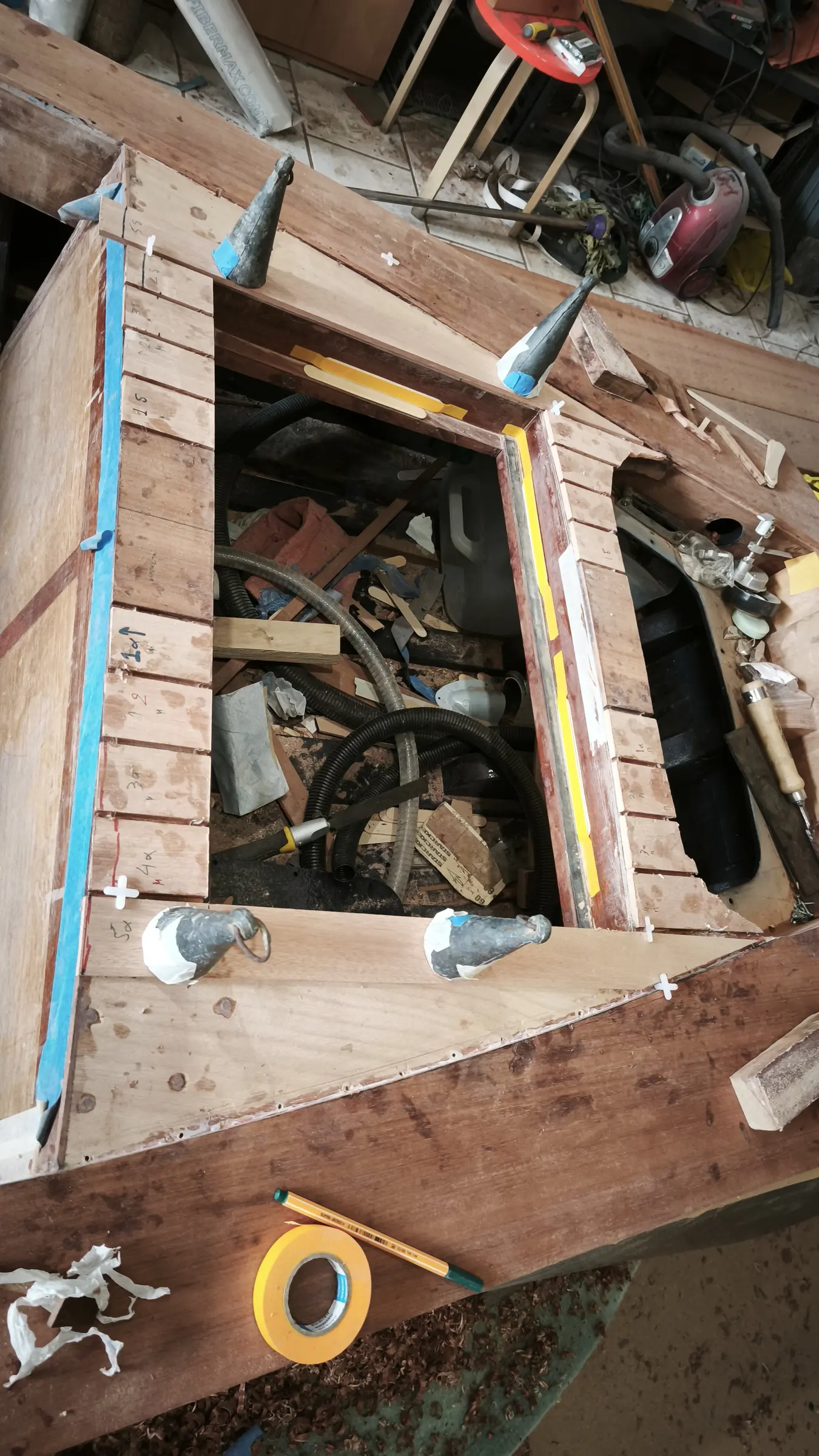
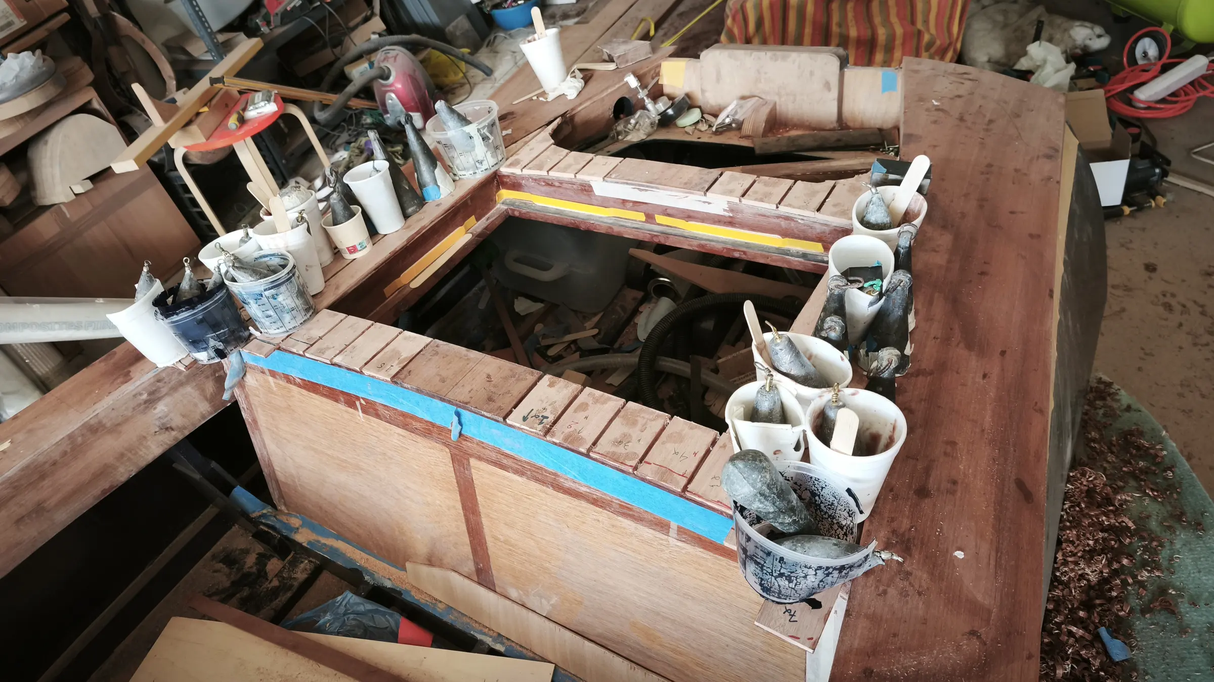
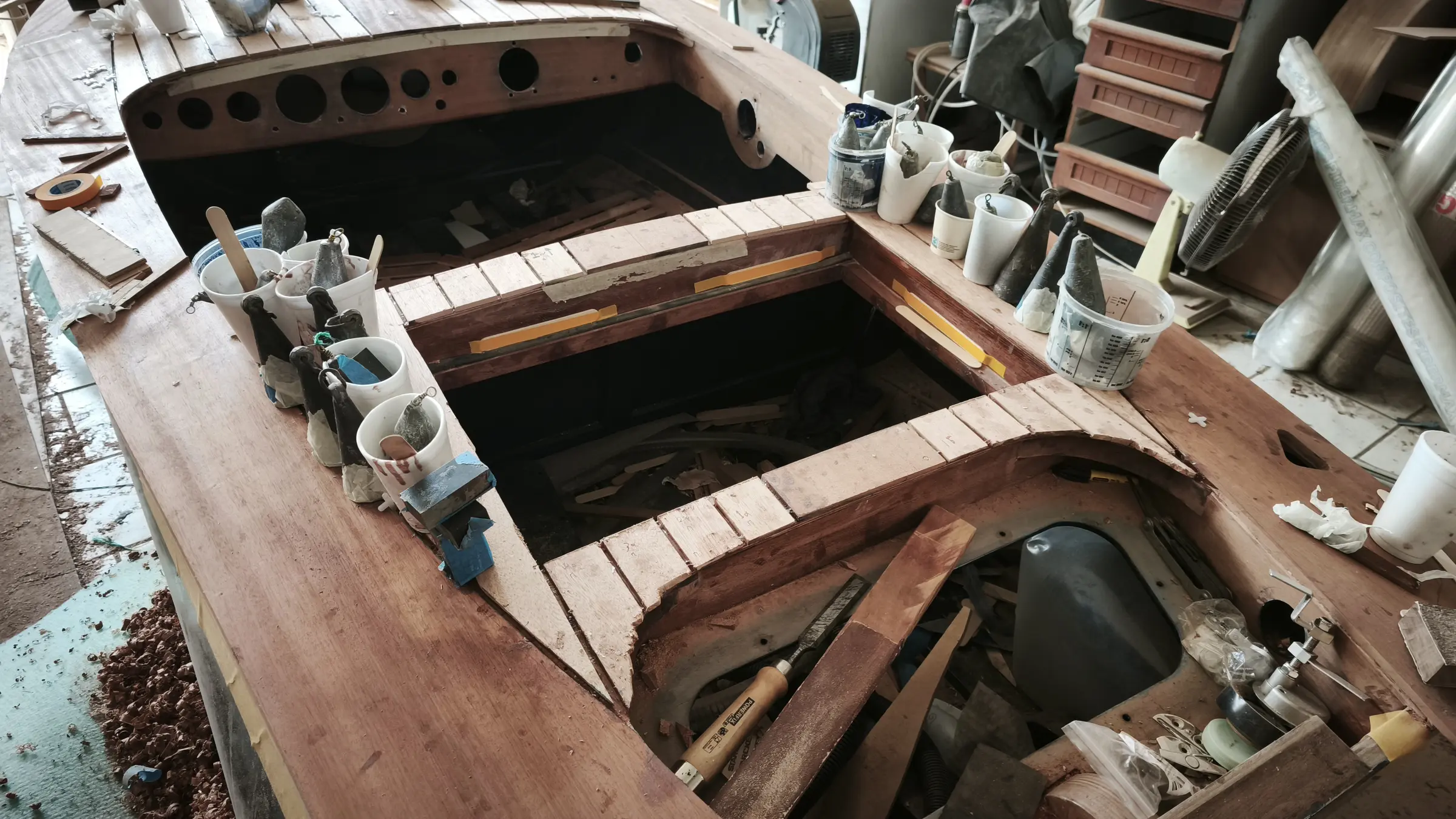
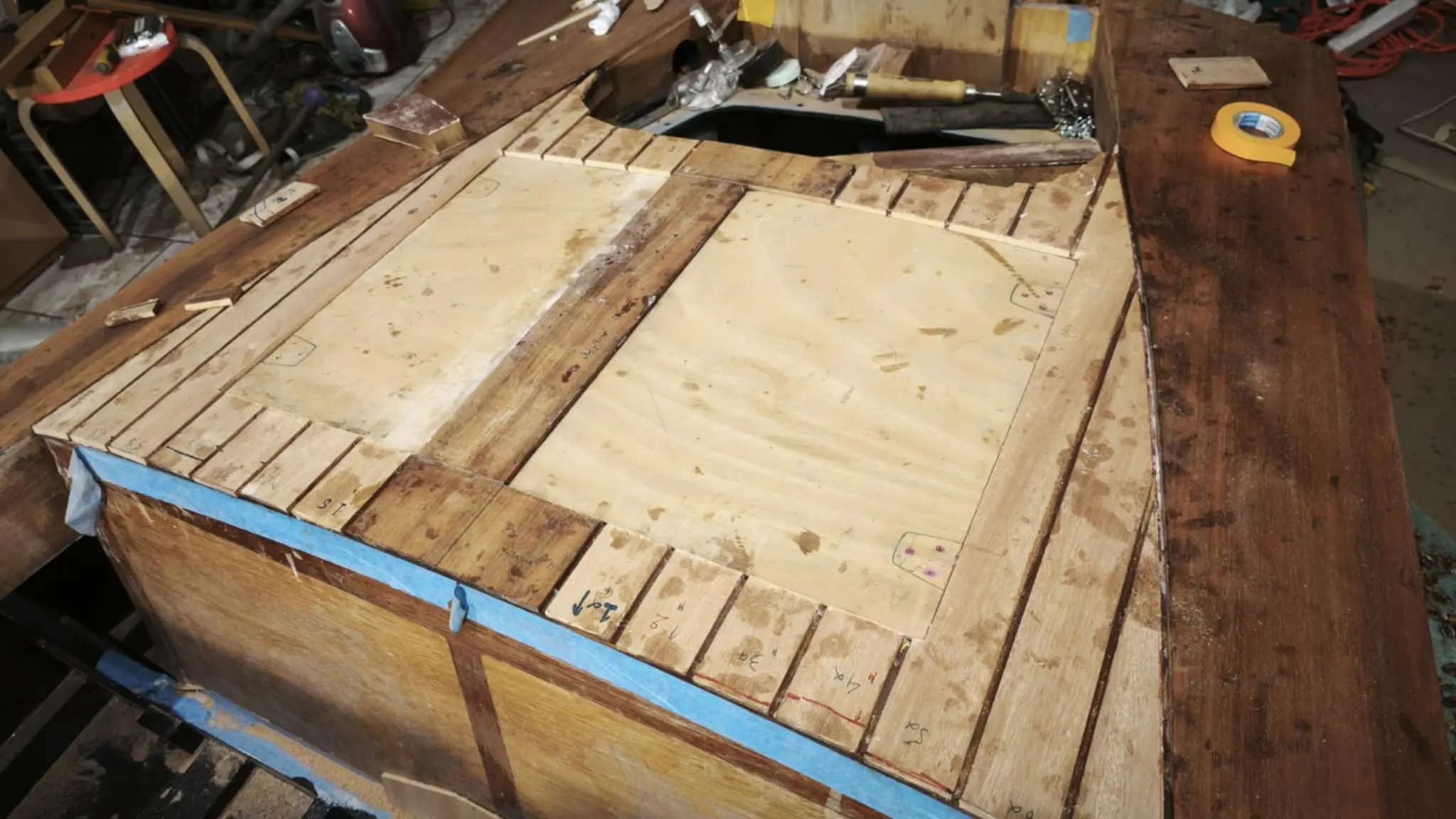
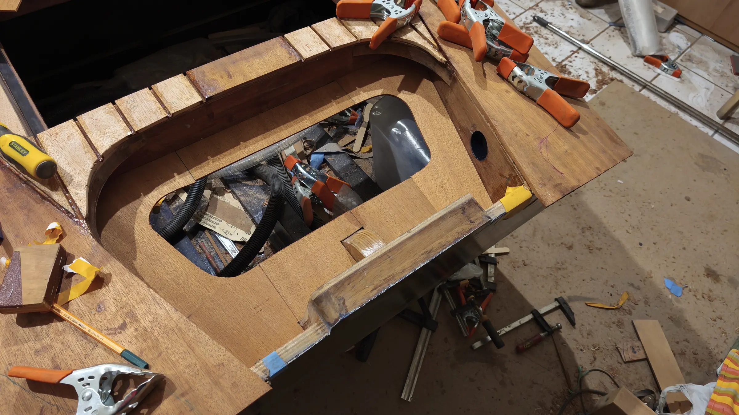
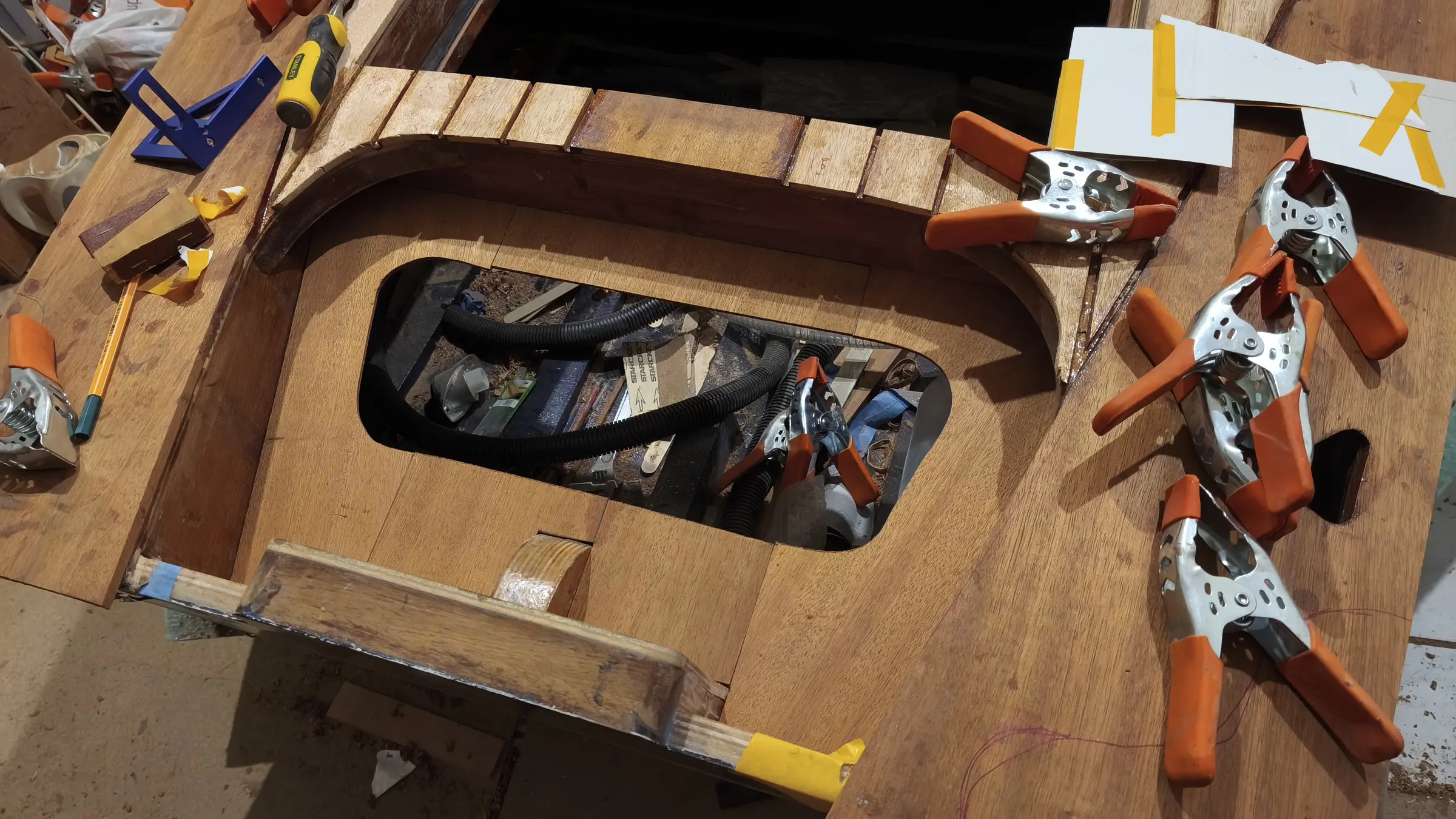
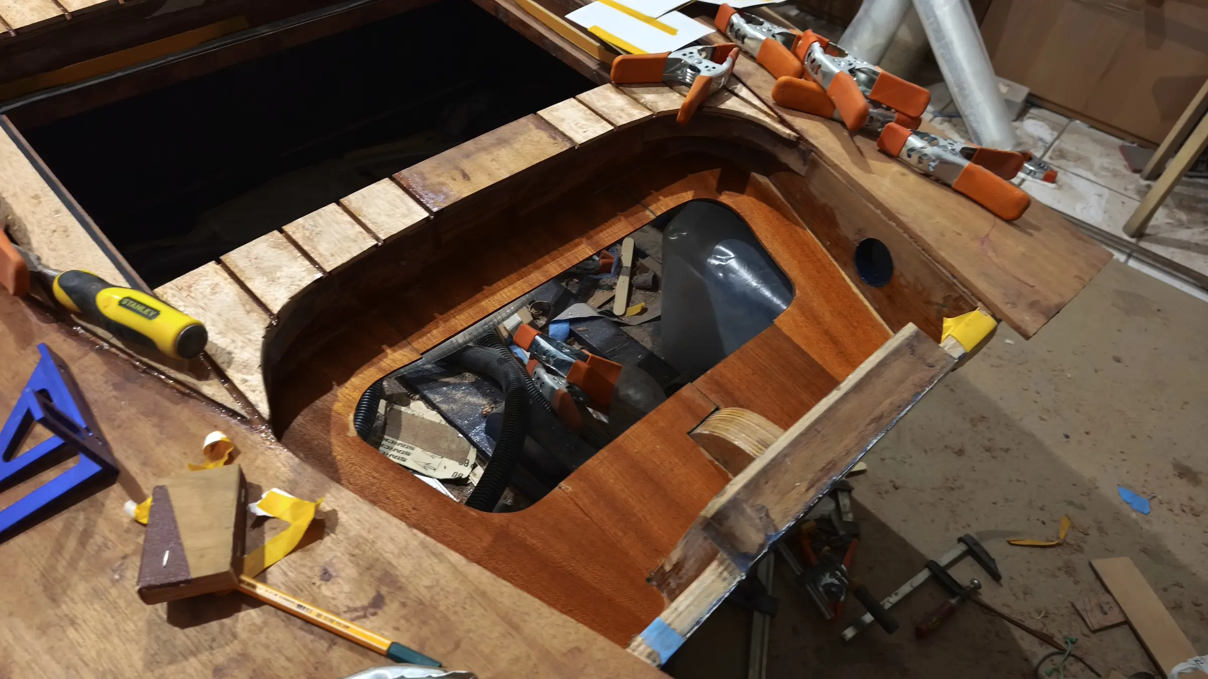
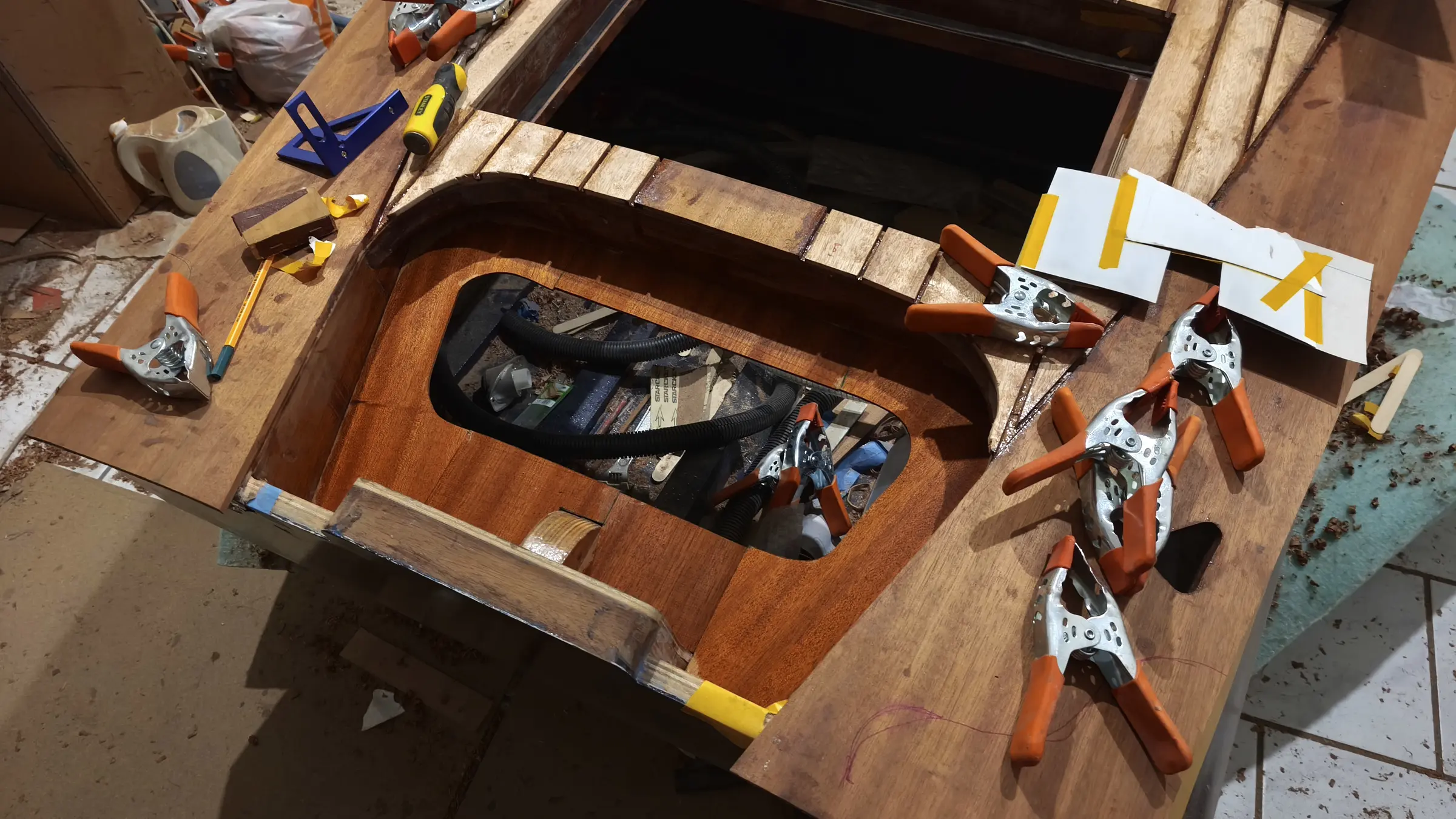
Glen-L Squirt 26 entries, 861 photos Back to the log

Set the paper to A4 or Letter, turn background graphics on so the cover photograph prints, and leave margins at their default. The page numbers and the chapter running heads are drawn by the browser into the page margins, so they exist only on paper: check the print preview rather than this screen for them, and turn Headers and footers off there so Chrome's own furniture does not crowd them out. Chrome and Edge print them, Safari and Firefox print the same book without them.

new build

Glen-L Squirt

Glen-L Squirt

George · 2021 to 2026

A build log

Glen-L Squirt

Glen-L Squirt


kept by George, Greece

2021 to 2026

The boat

Glen-L Squirt

Built by
George
Built at
Greece

What it took

By the numbers

371
Hours at the boat
61 months
From first day to last
26
Days written up
861
Photographs
15,905
Words written
€8,937
Spent in all
Went into the boat €7,767.94
Tool or consumable €1,168.70
Total€8,936.64

20 h

Choosing the boat, and getting ready

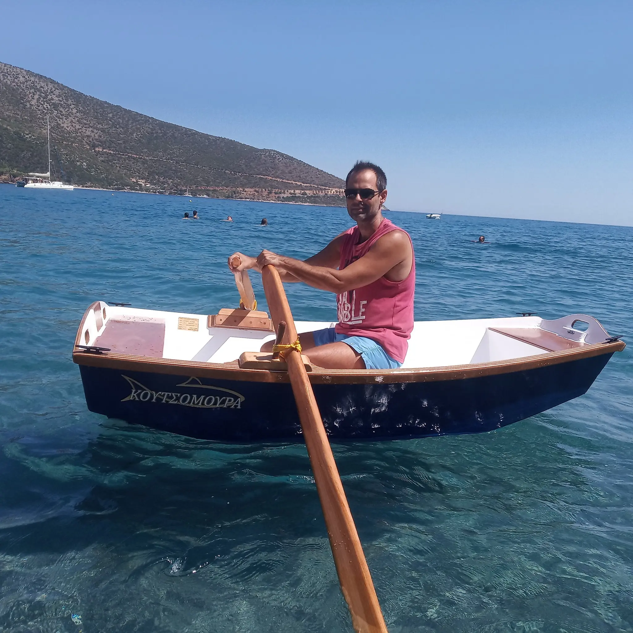
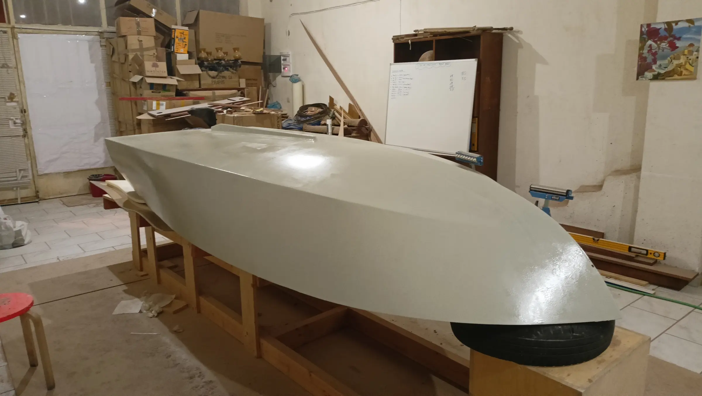
The idea of building a boat came to me very early, in childhood. The first attempt was a failed surfboard. Thirty-five years later came the second attempt, a very small boat for fishing close to shore. At the time of writing this post it is 90% finished and being built back in the village. If I manage to get there at Easter it should be done.

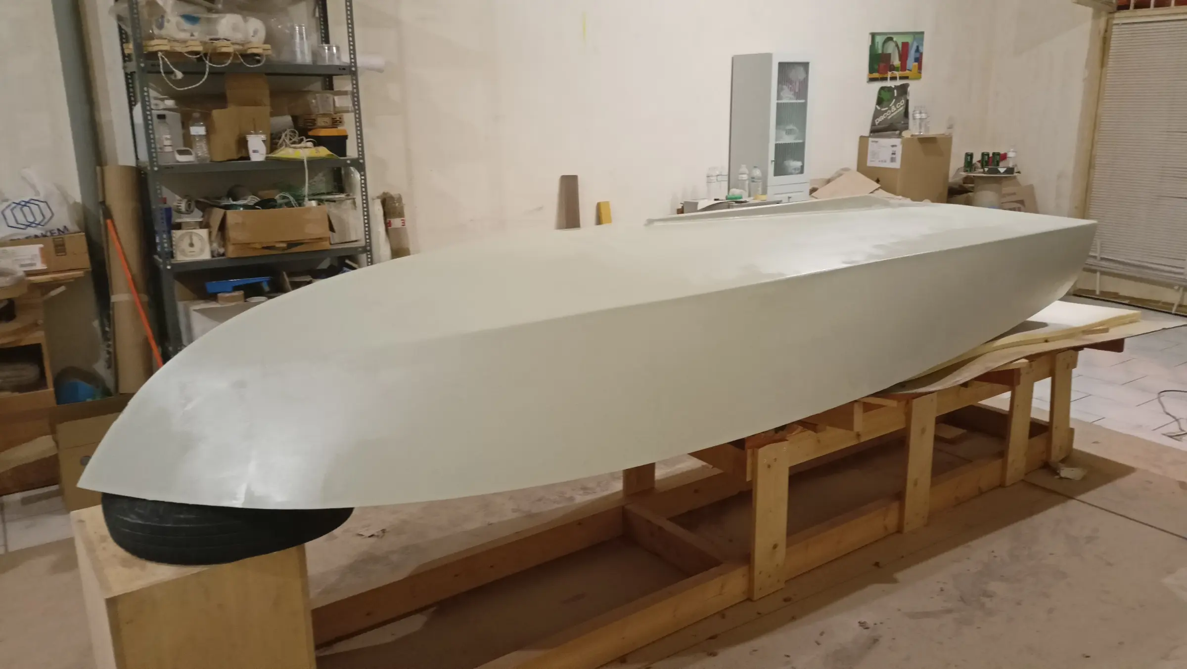
(edit: it's finished!!! it's the one below)

Now it is time for something harder. A small runabout.

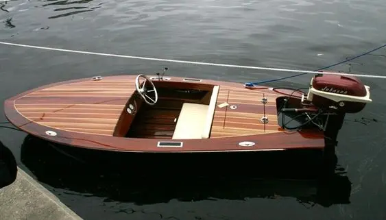
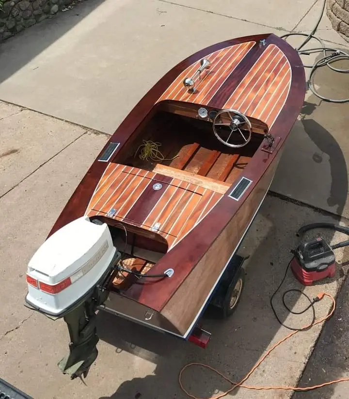
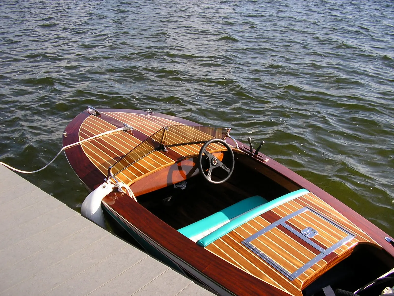
The choice was easy, the moment the photograph below landed in front of me.

It is a 1950 design, the Squirt, from Glen-L.

The boat will be built from sapele, marine okoume plywood, fiberglass cloth and an epoxy resin made for boatbuilding.

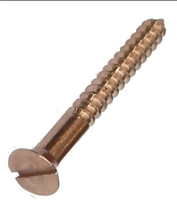
The timber will be joined with silicon bronze screws which, of course, were not available in Greece. I tracked them down and bought them from England.

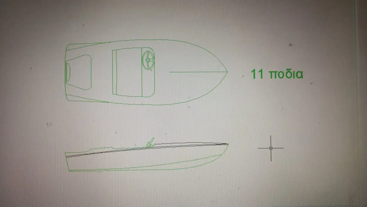
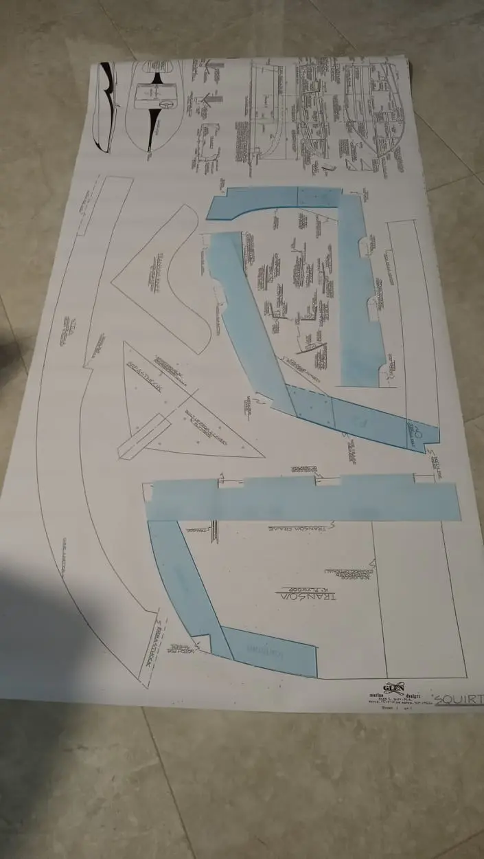
I also bought the plans from the company's website.

After a good deal of thought I decided to stretch the boat slightly and change the plans a little. Overall length will be 3.35 m.

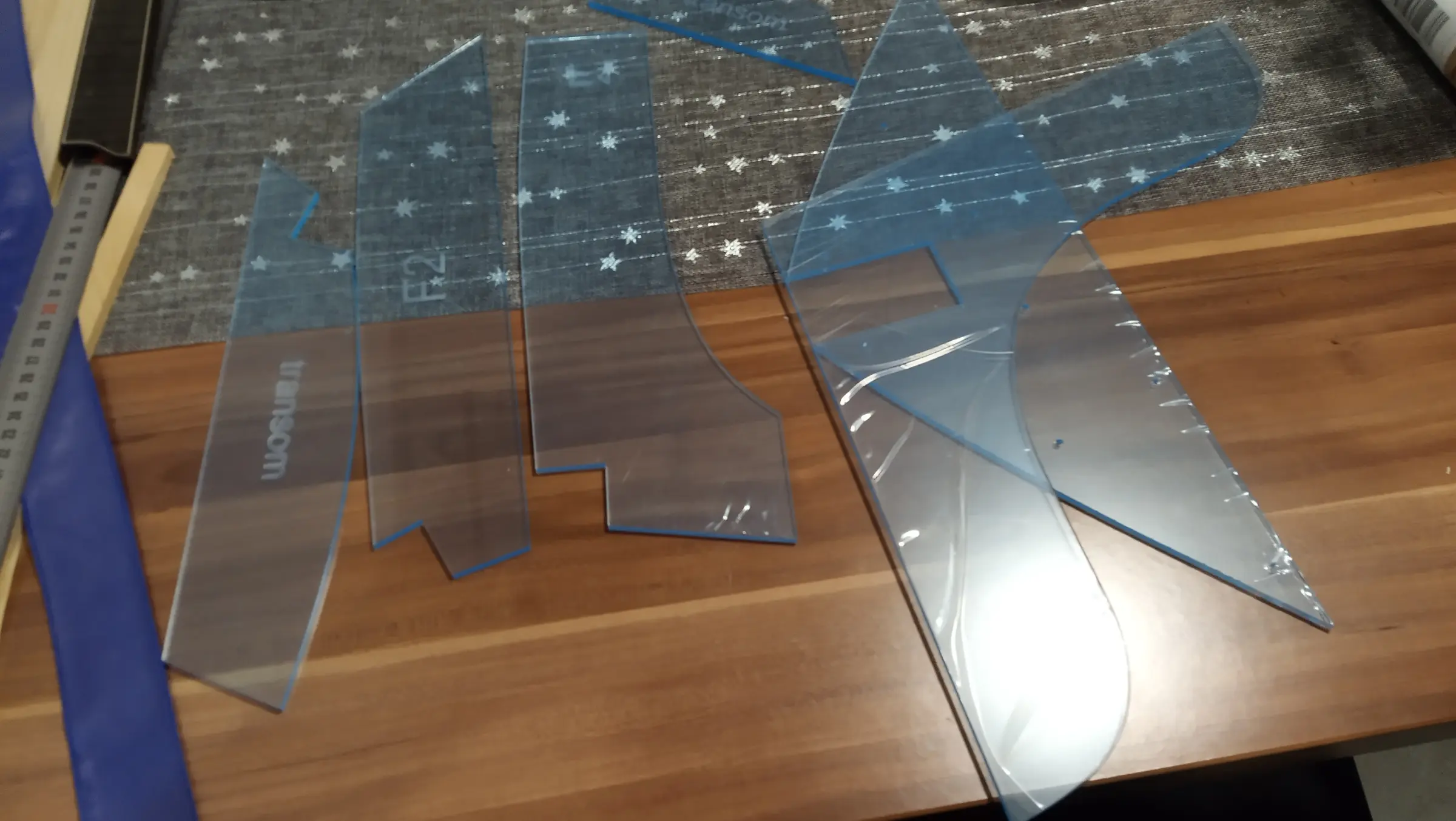
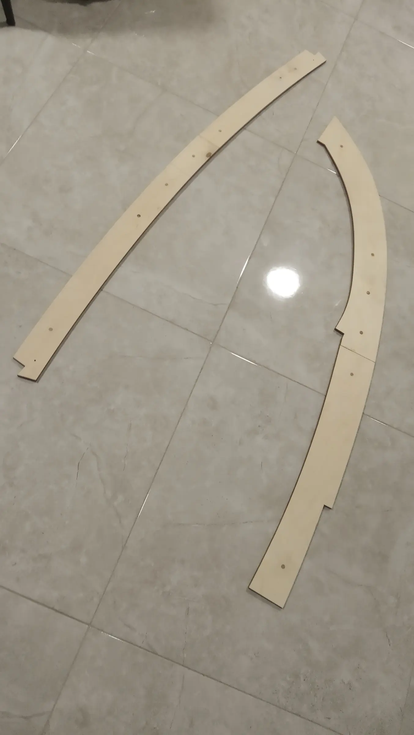
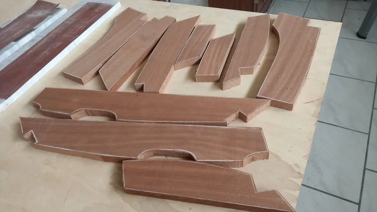
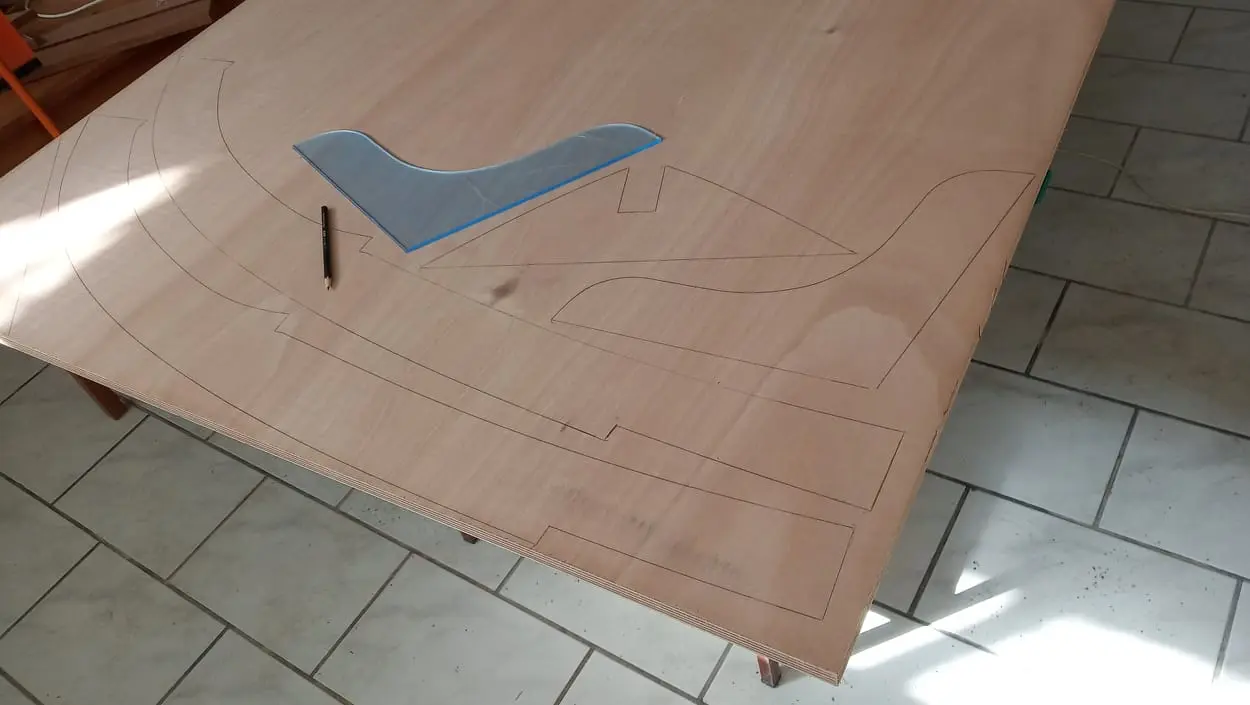
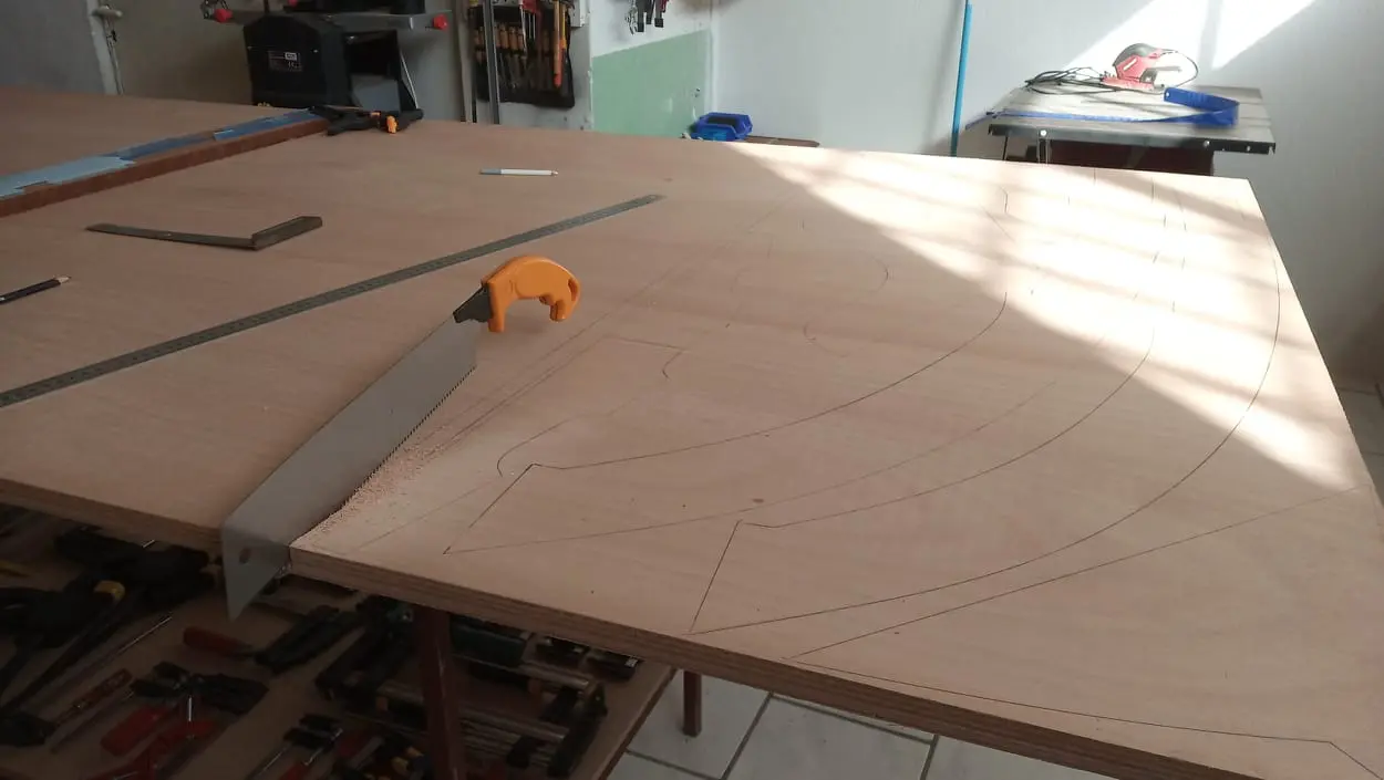
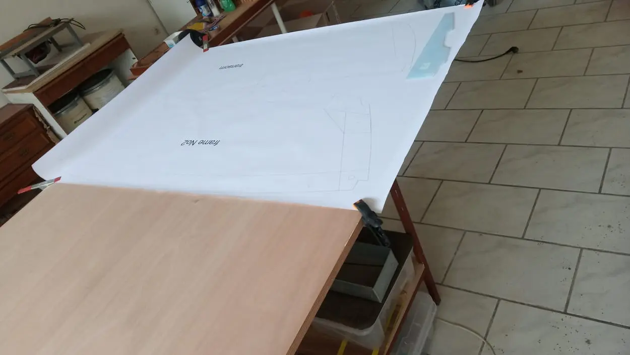
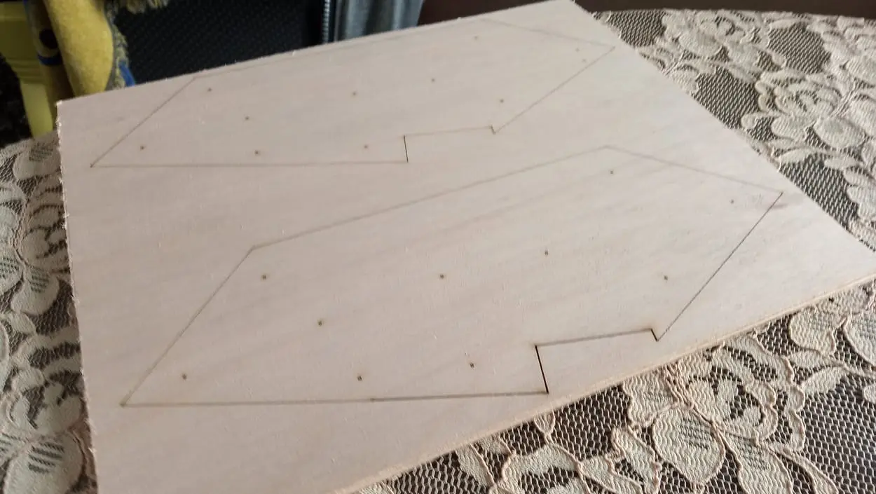
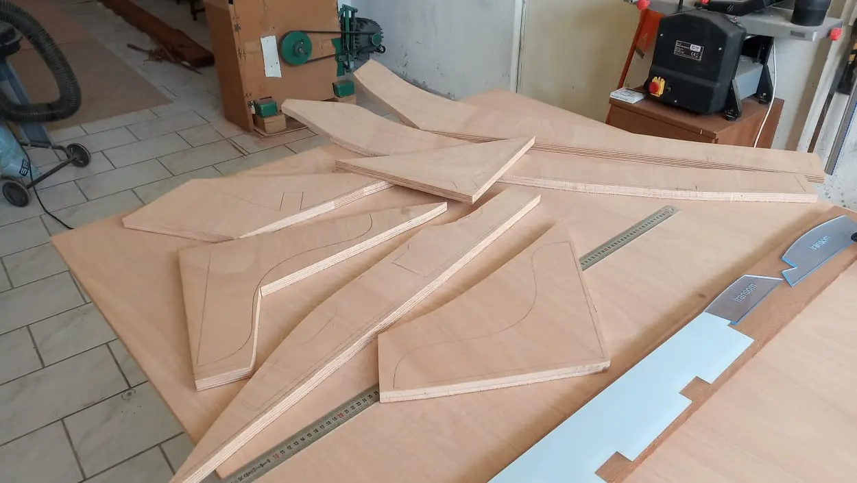
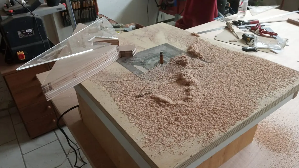
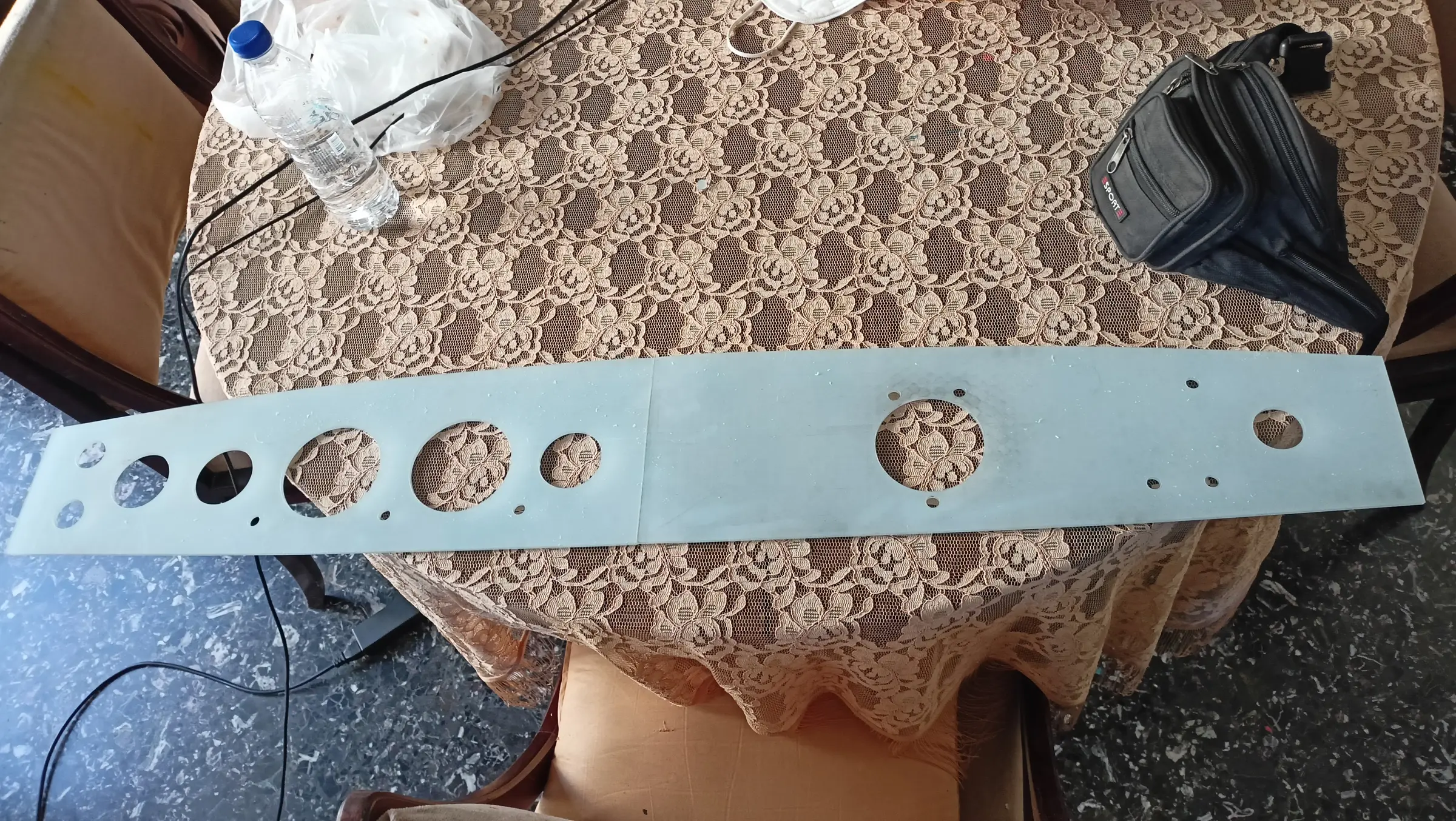
For the frames, the transom and the keel I decided to make templates out of plexiglass. So the plans were digitised in AutoCAD and laser cut. Anything too big to go in the laser was cut on a friend's CNC, in two pieces with an overlapping section on both and dowels to locate them exactly.

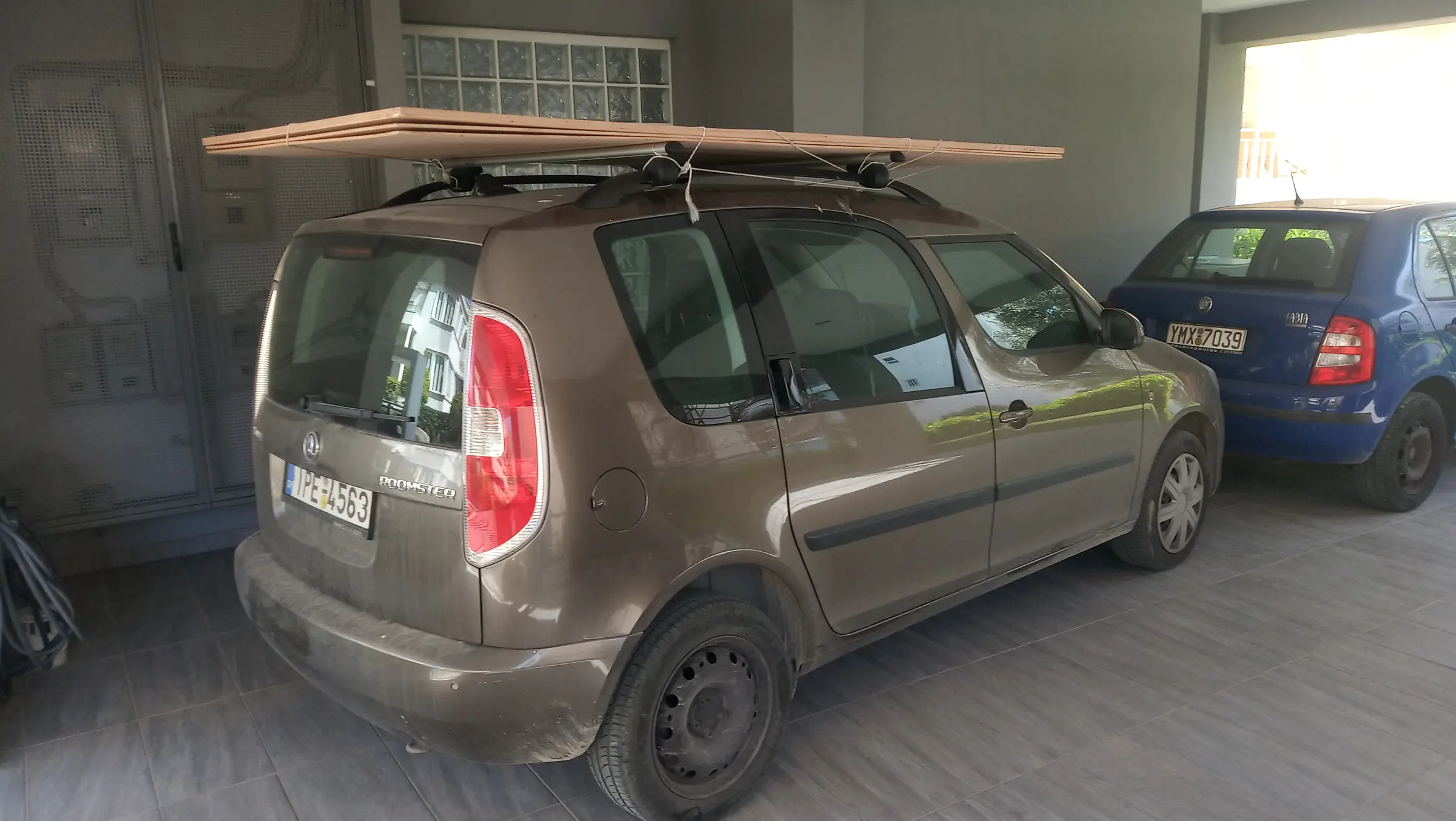
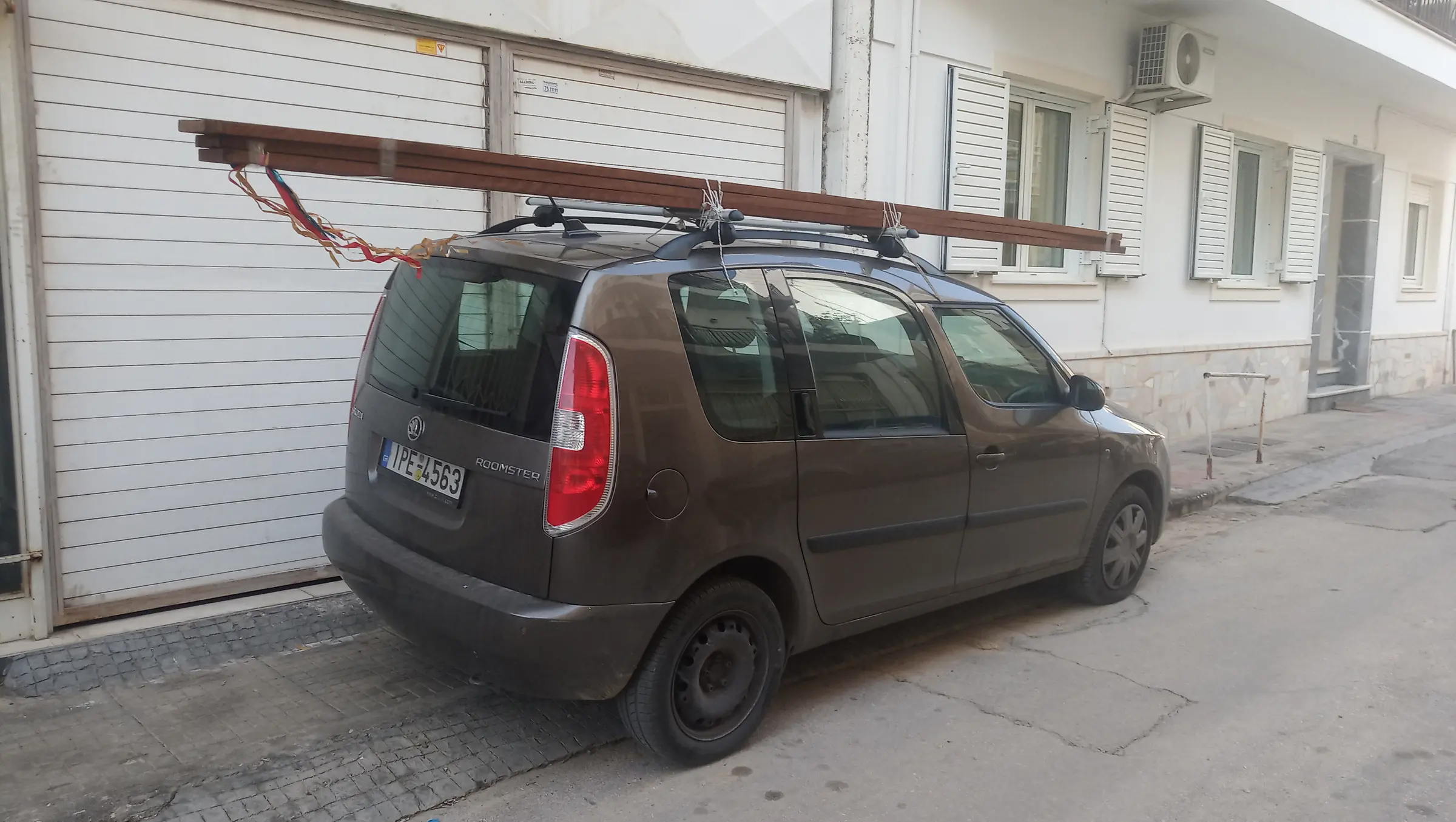
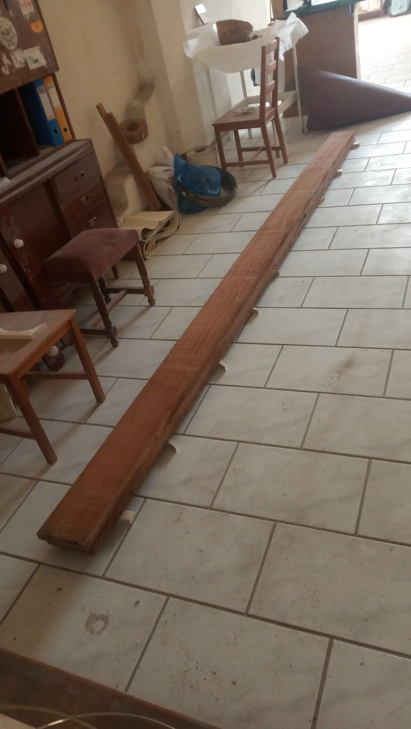
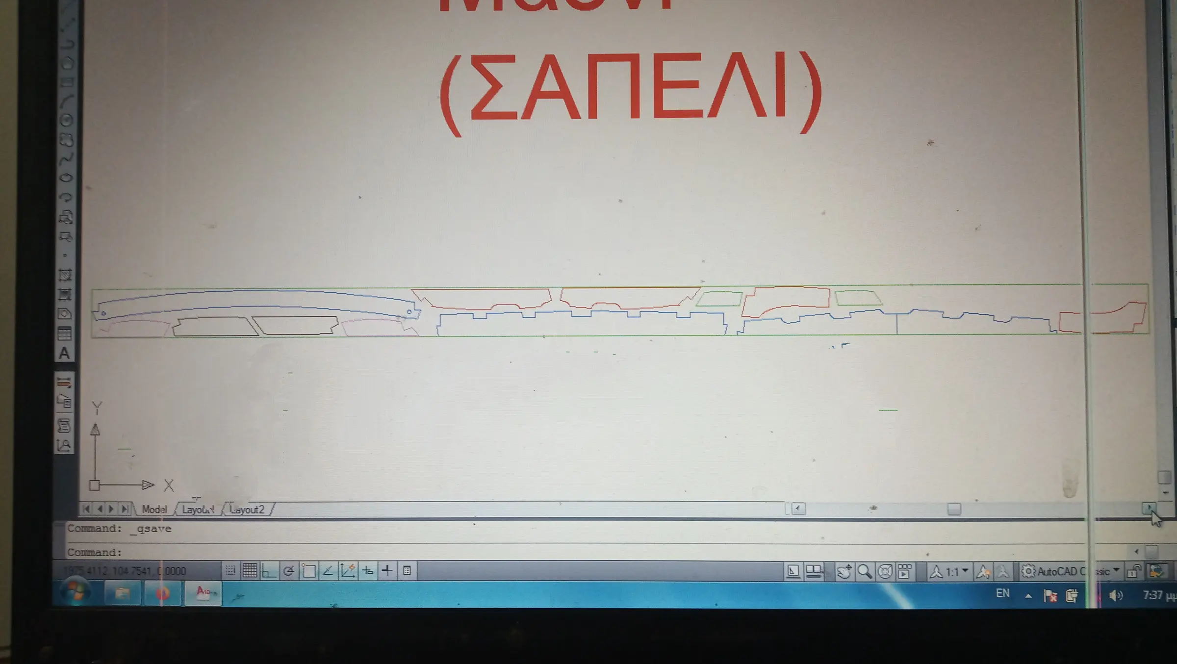
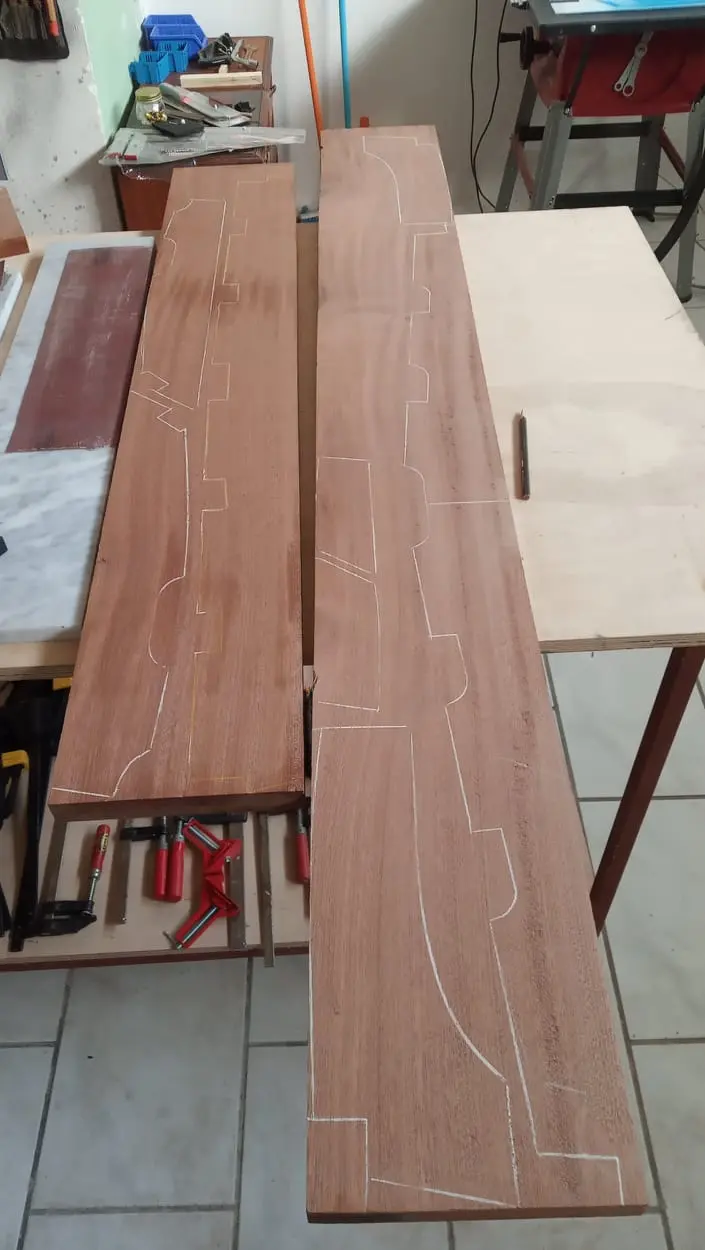
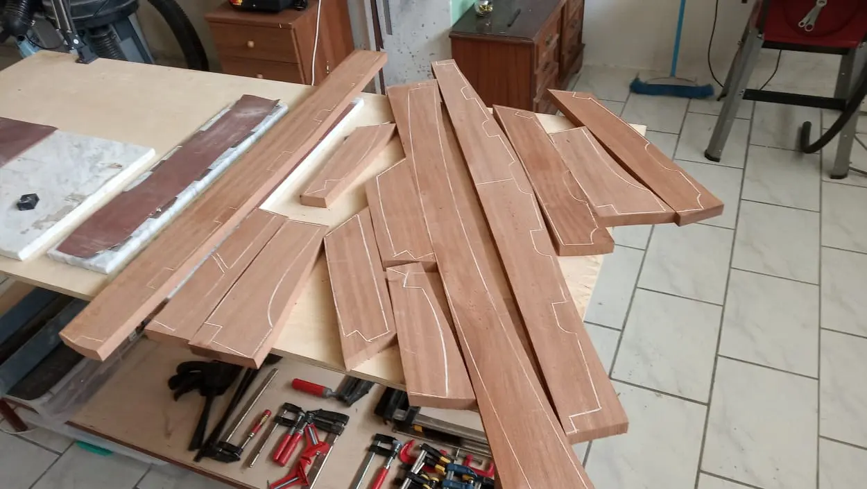
Finally I bought the sapele and the 20 mm and 6 mm marine okoume plywood from a timber merchant in Perama that stocks boatbuilding timber. I picked the straightest grain I could find, though there was not much to choose from. Back in AutoCAD, I worked out how the pieces would be cut from the board.

Cost of materials

So far:

100 euros for the plans

190 euros for the screws

150 euros for the sapele

160 euros for one sheet of 20 mm okoume plywood and two sheets of 6 mm

(and 150 euros for boatbuilding books)

So this is the place where I will show the work as I go. I honestly do not know whether I will manage it, since I am not a naval architect, nor a joiner with a lot of experience in wood, and I do not have professional tools. What is certain is that I am going to enjoy it.

So if you would like to enjoy it too, either to laugh at my mistakes or because you find something of interest in it, you are welcome to follow along.

It will certainly take a good few years...


15 h

Building the frames, keel and transom

With the materials gathered, work began on the pieces that make up the frames, the keel and the transom.

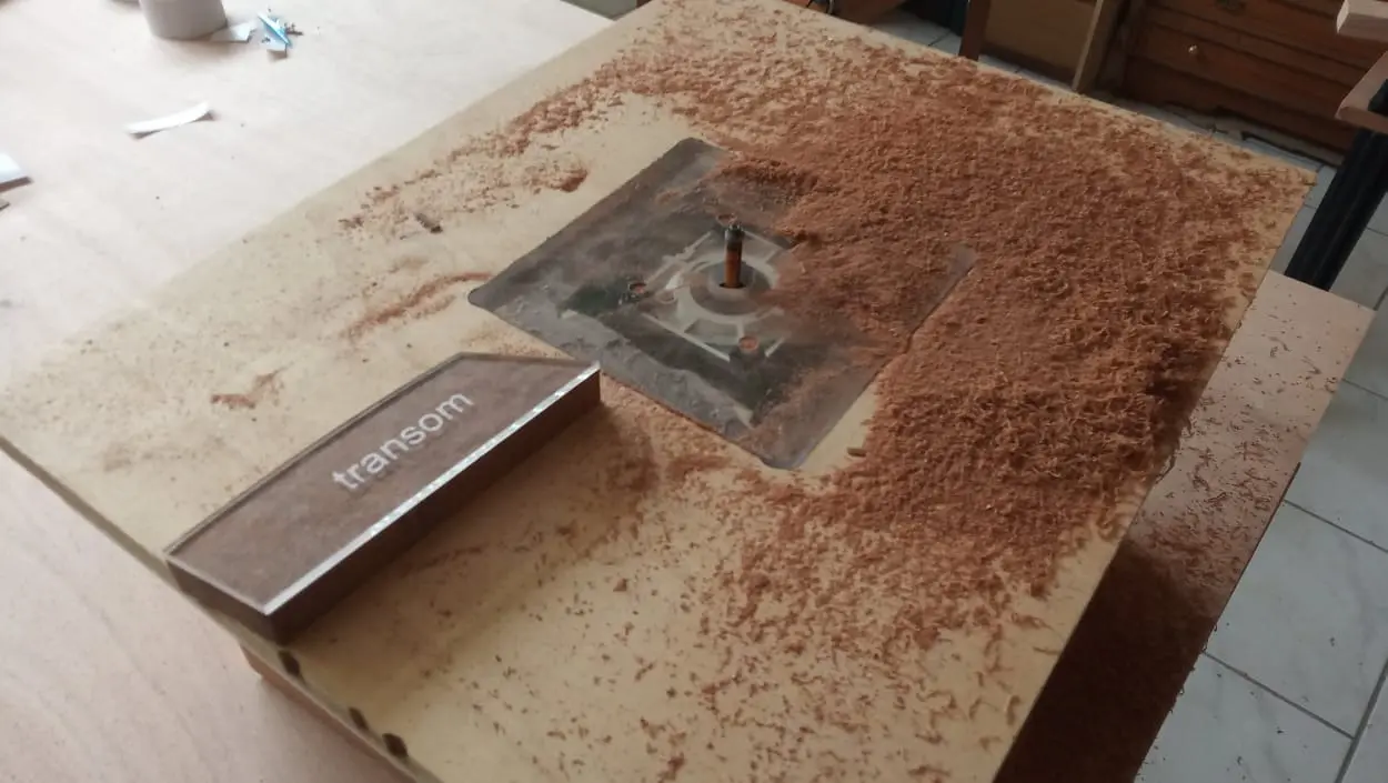
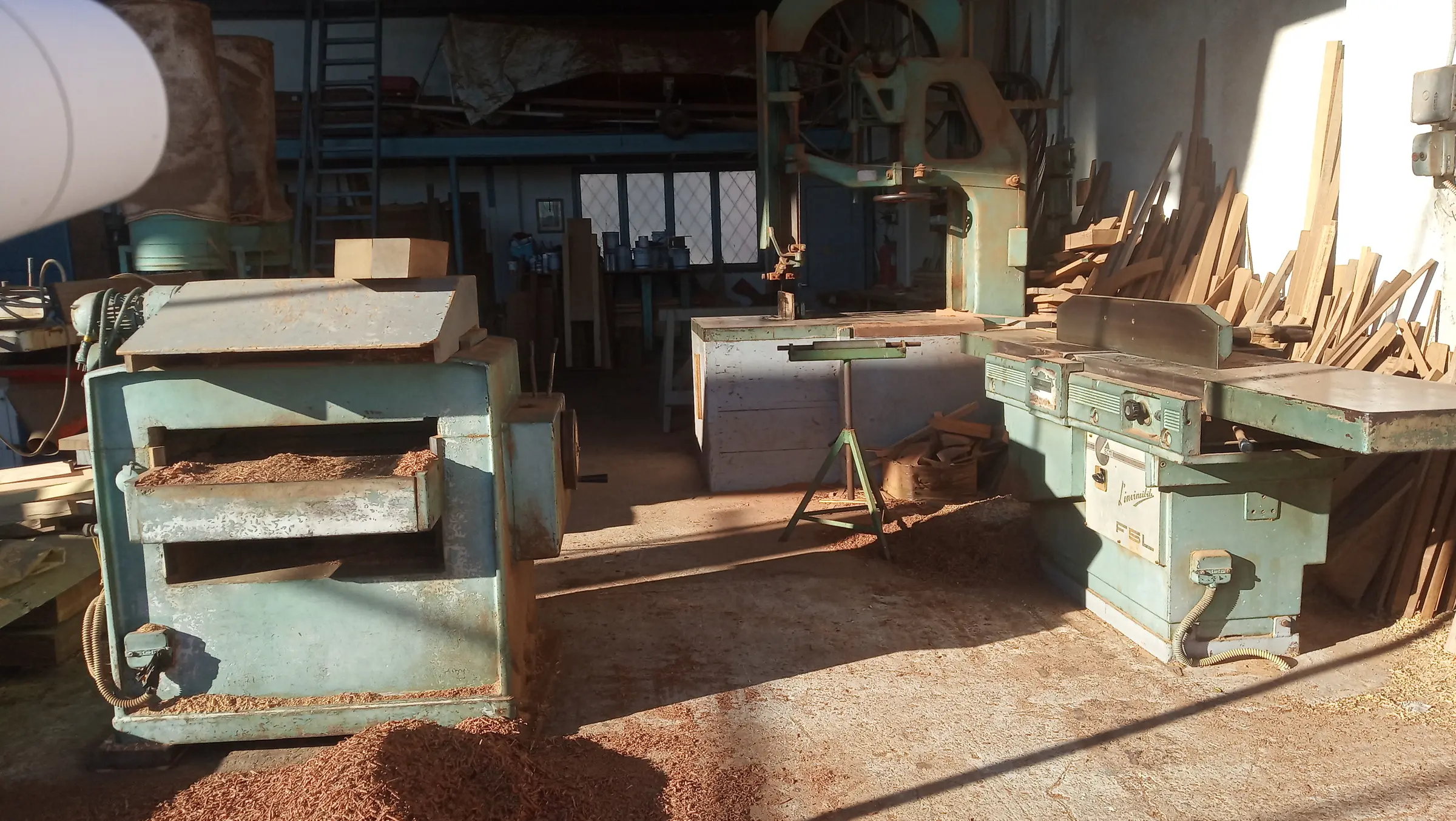
The parts were marked out on the sapele and the plywood, cut on the bandsaw, thicknessed to 20 mm on a joiner friend's planer (after I saw that mine could not manage it very well) and then routing began using the templates. Along the way I realised that the little 600 watt router was not going to do the job, so I bought a bigger 2.2 kW one with 12 mm cutters, and built a new, larger router table for it.

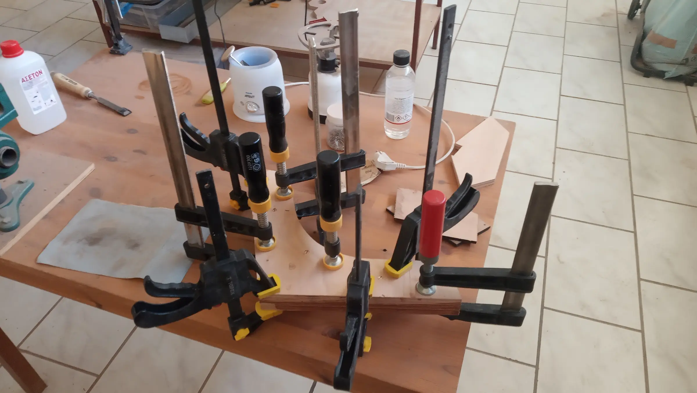
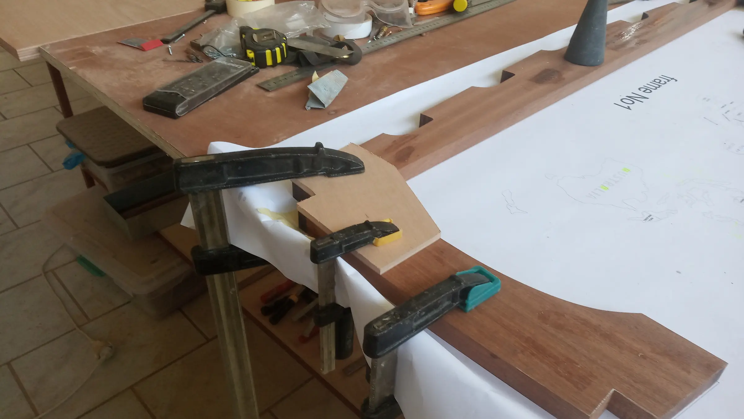
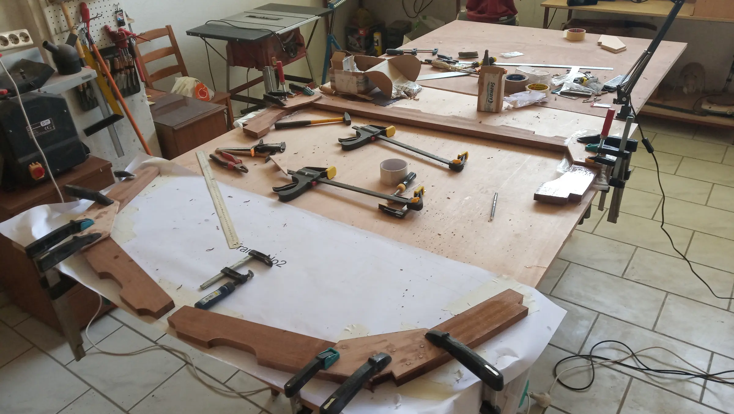
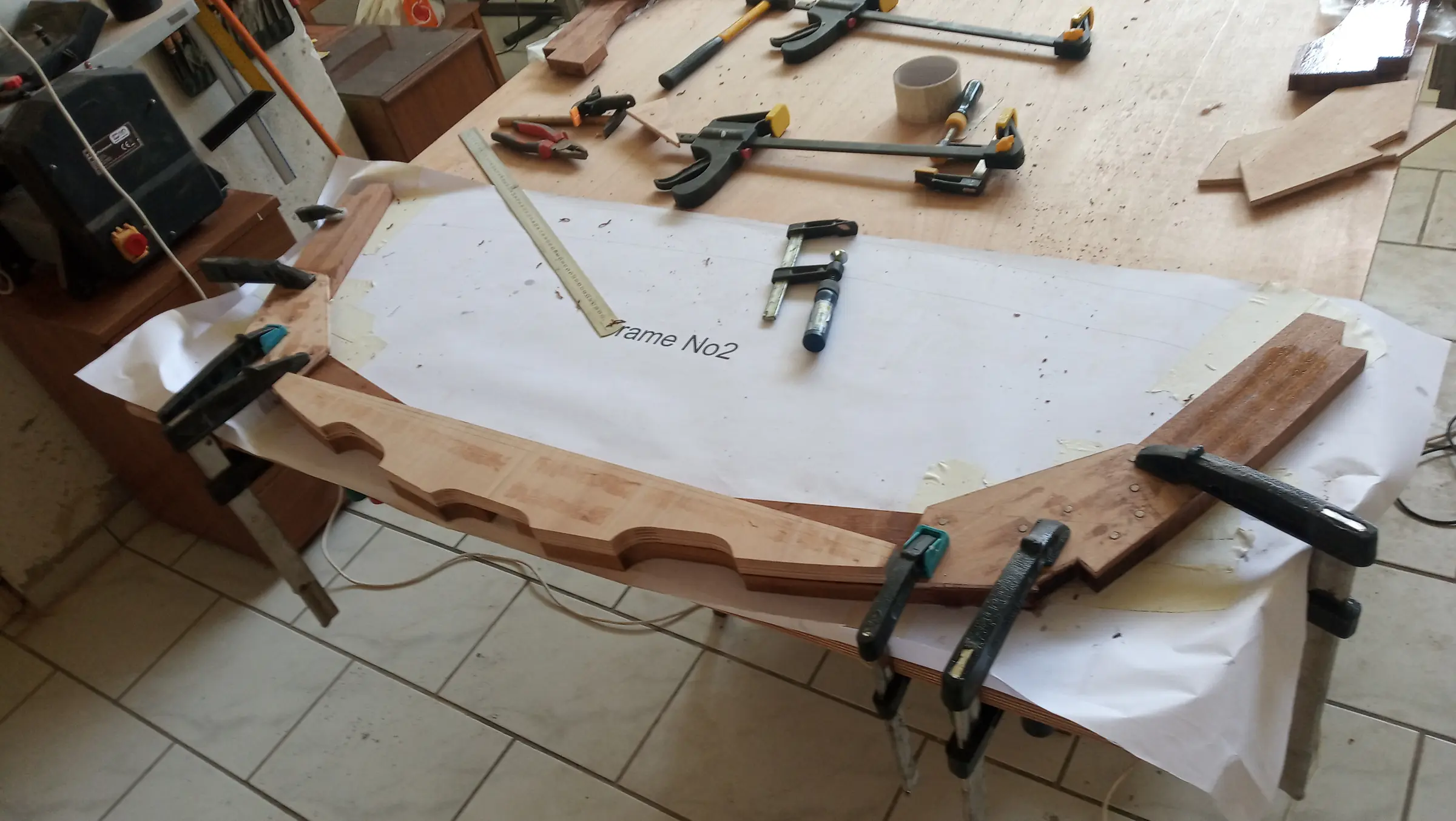
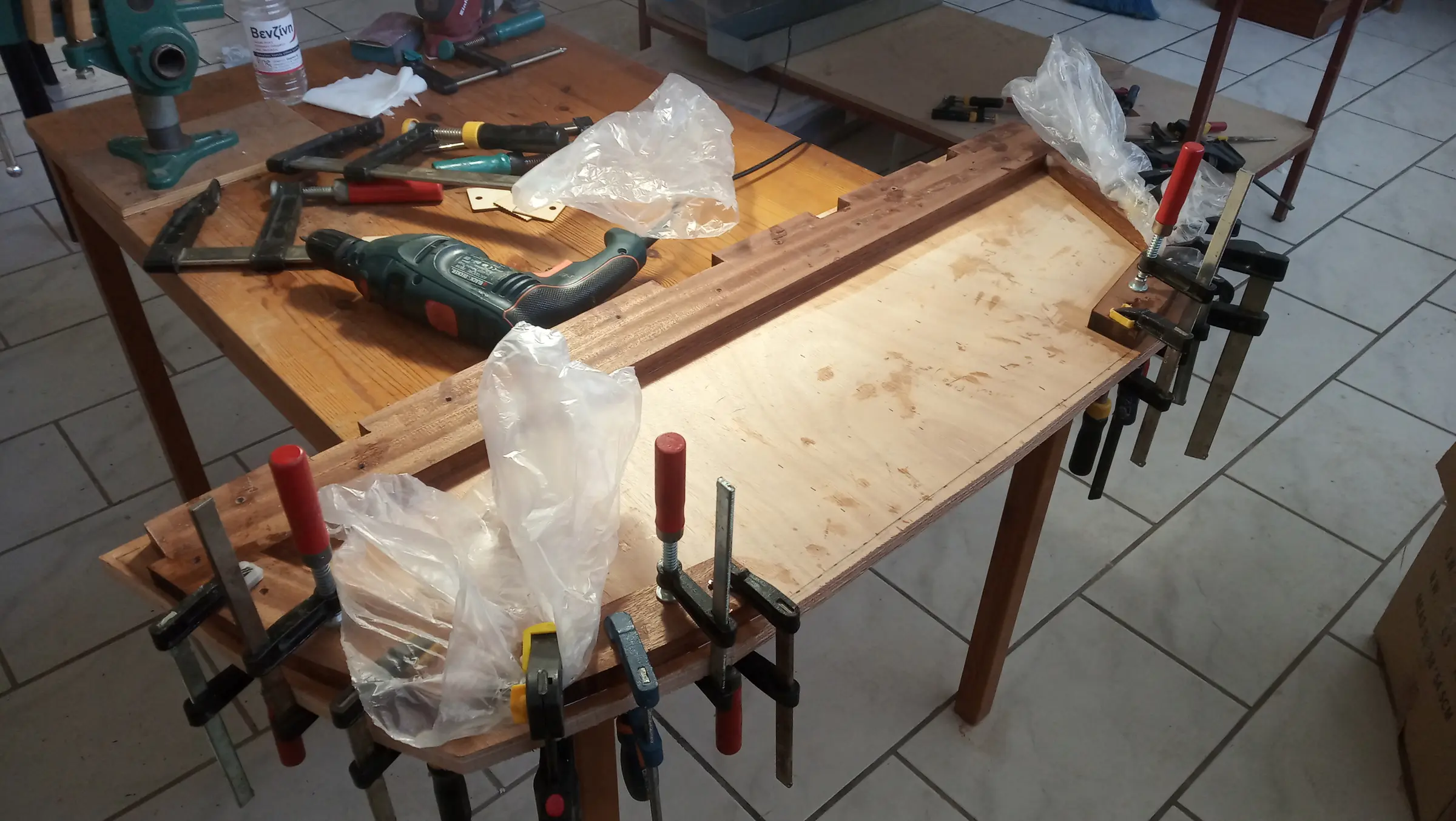
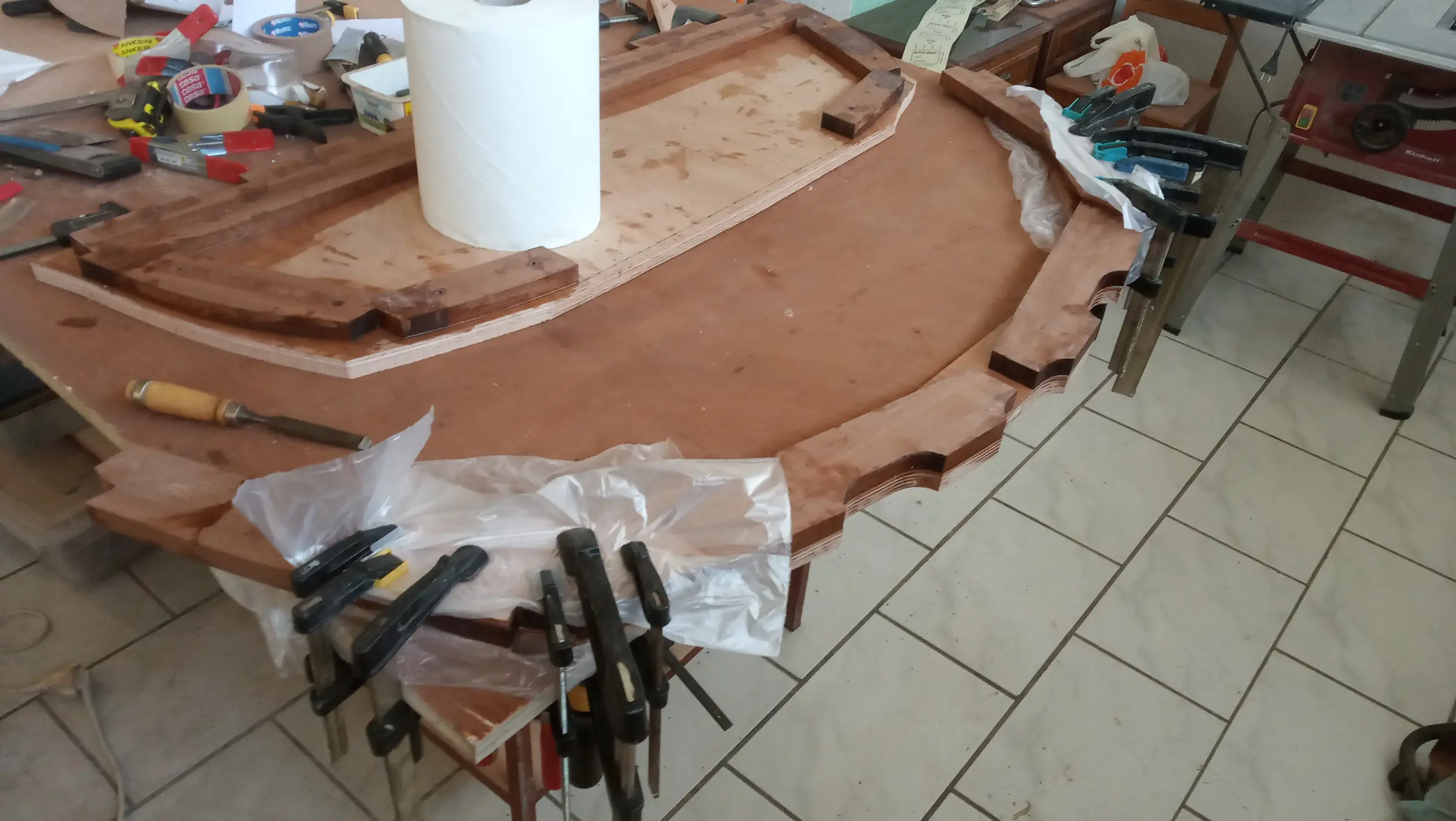
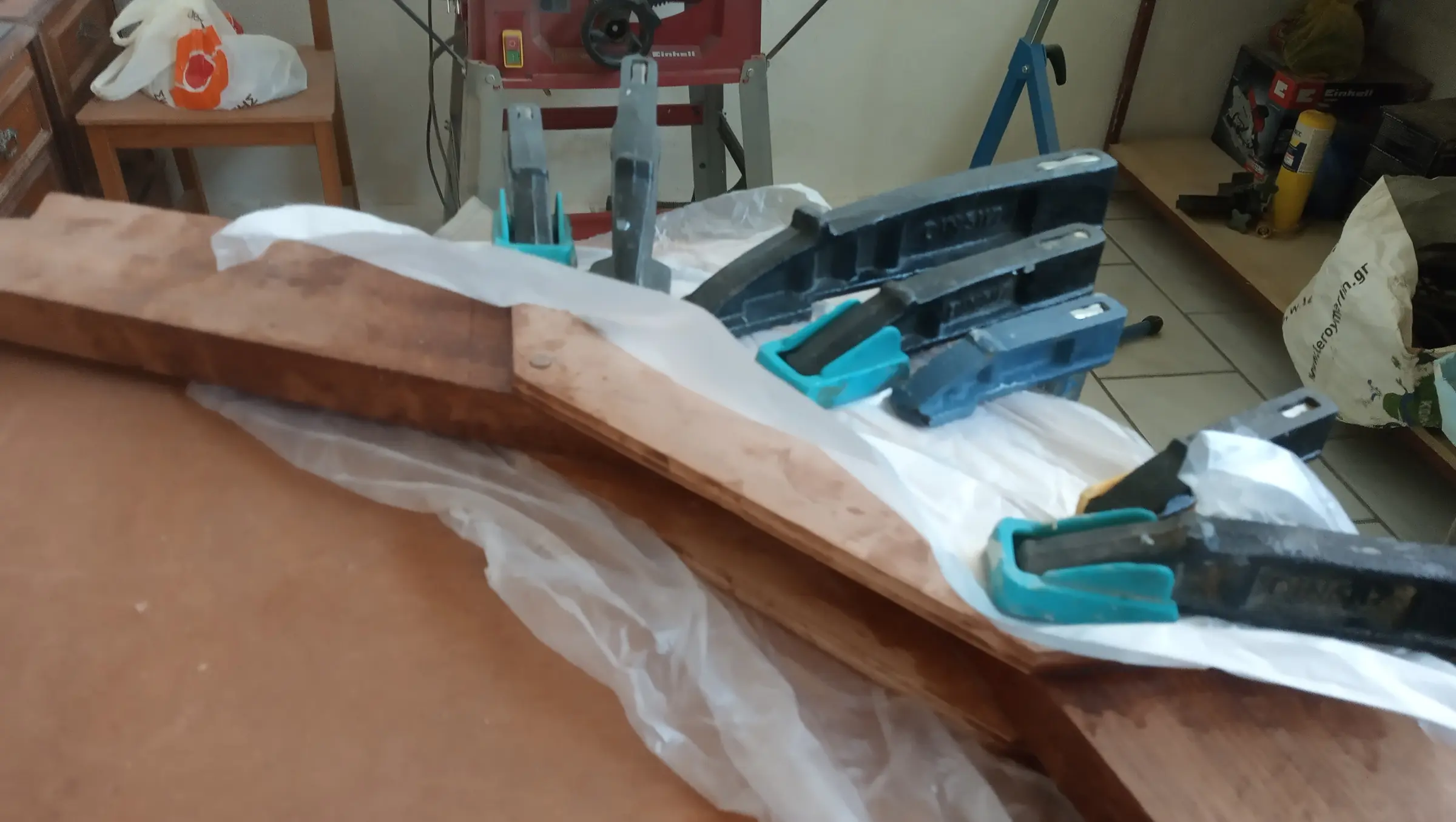
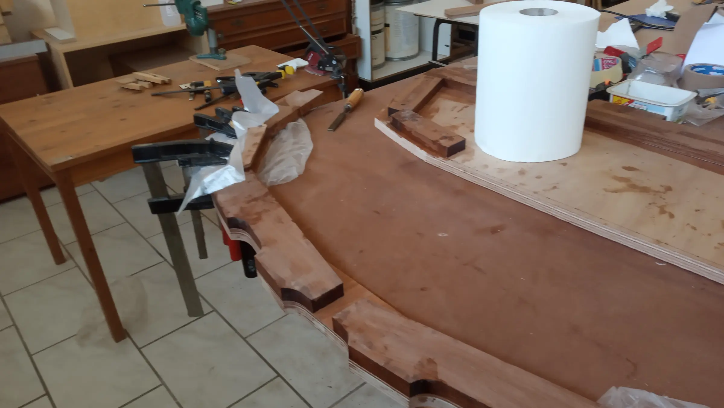
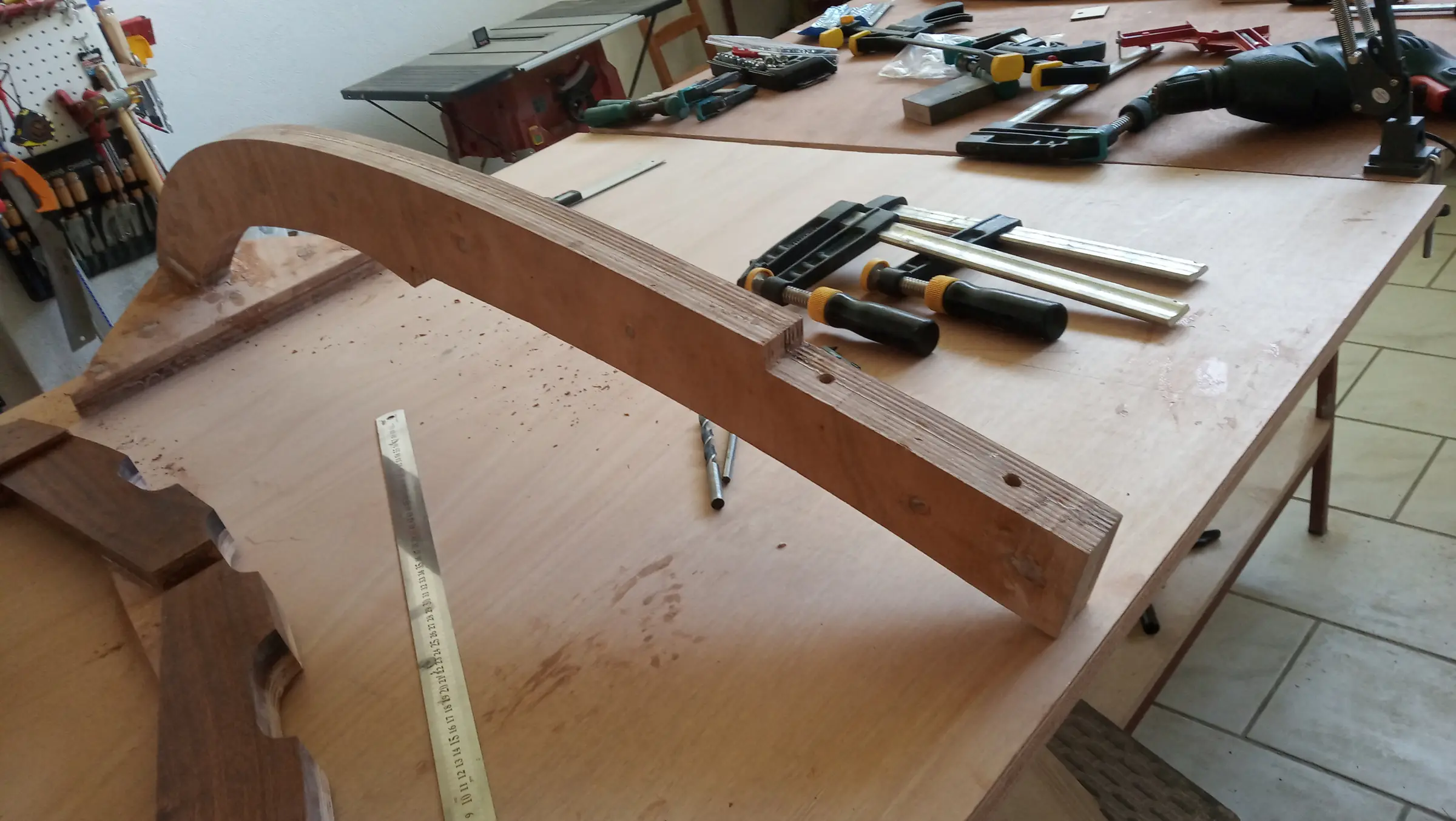
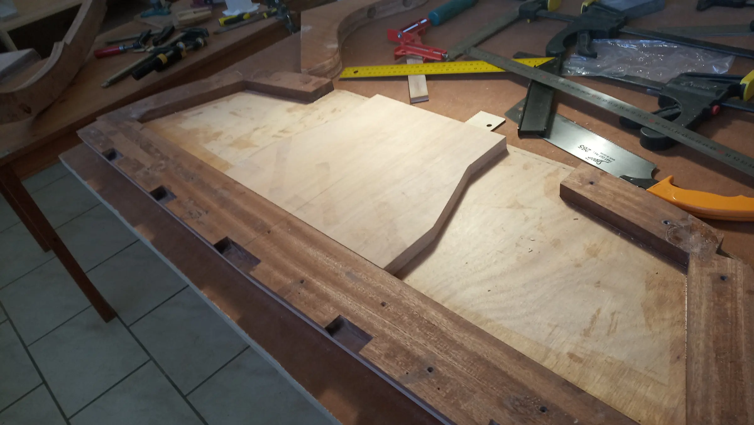
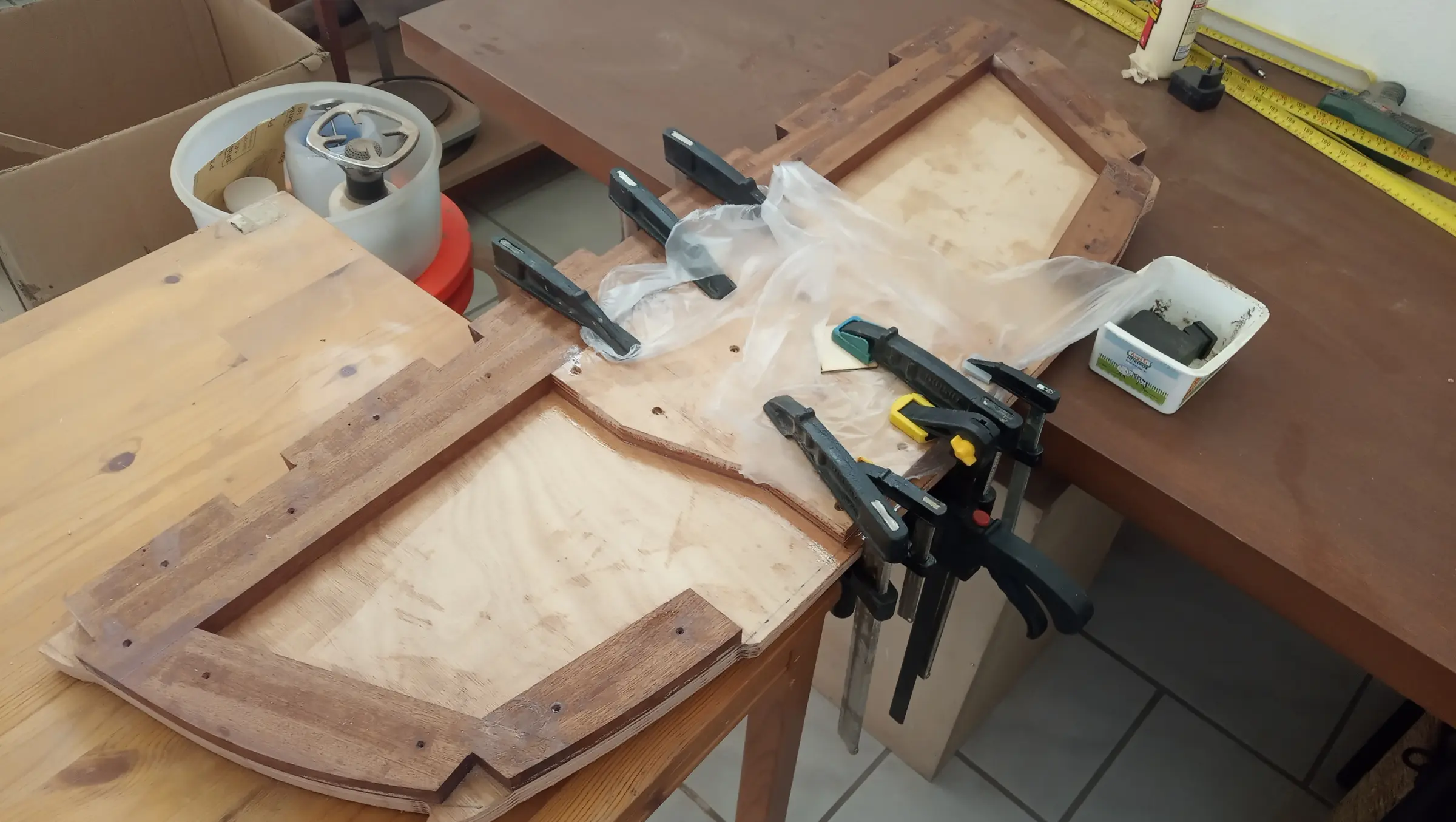
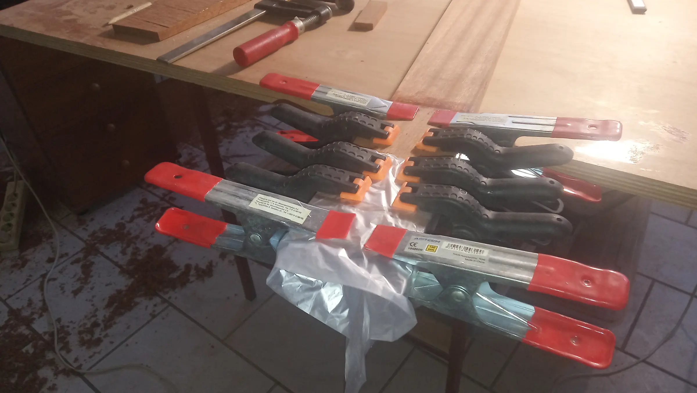
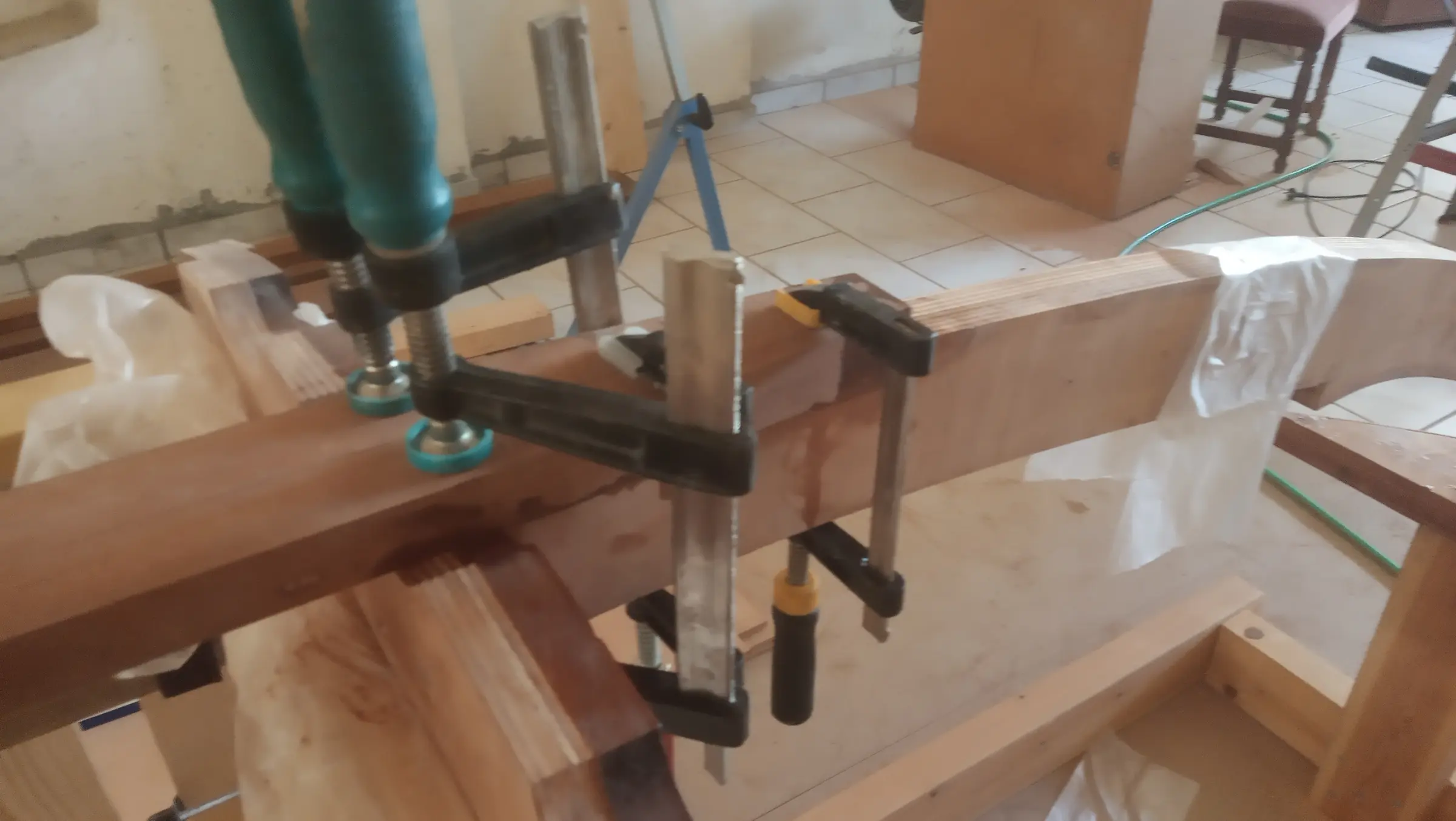
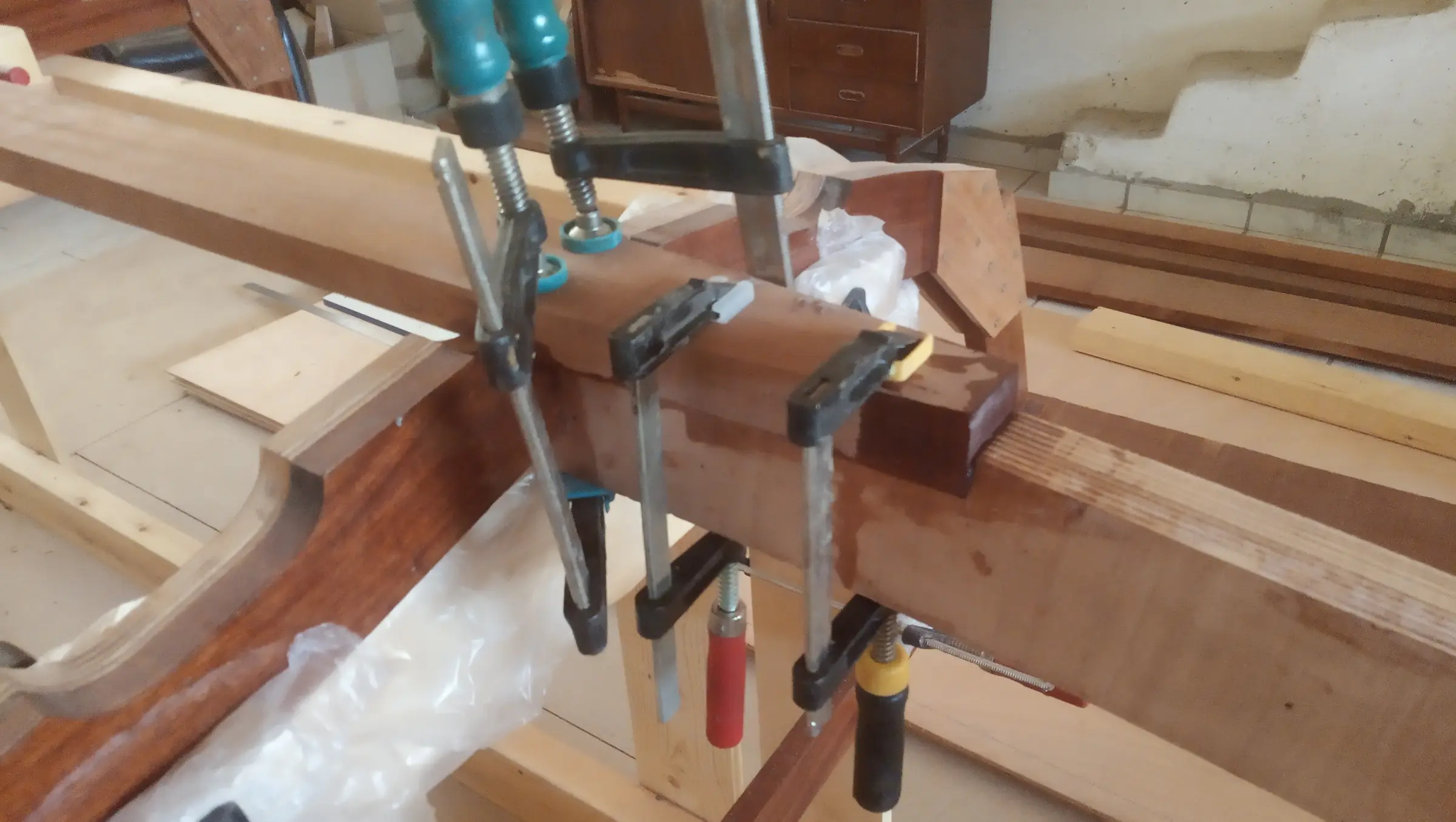
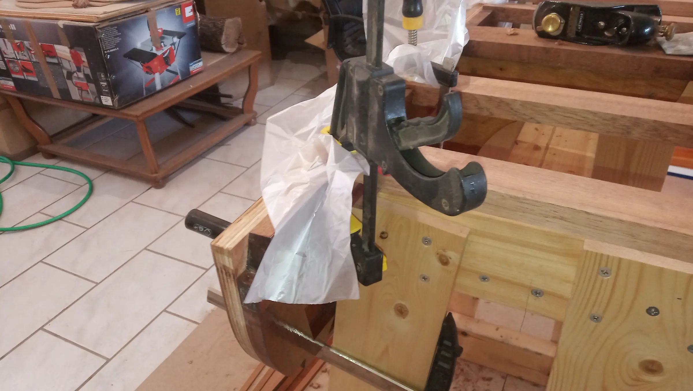
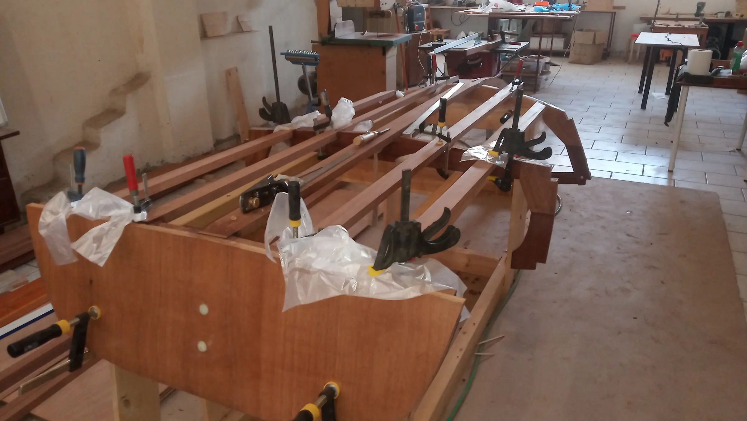
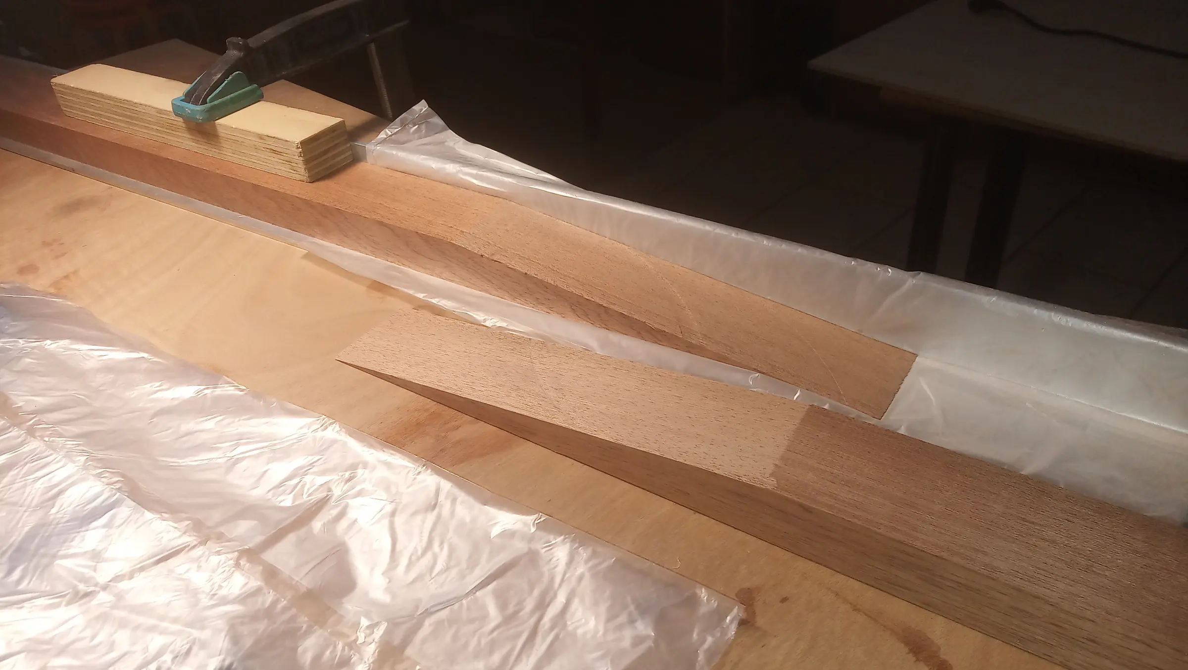
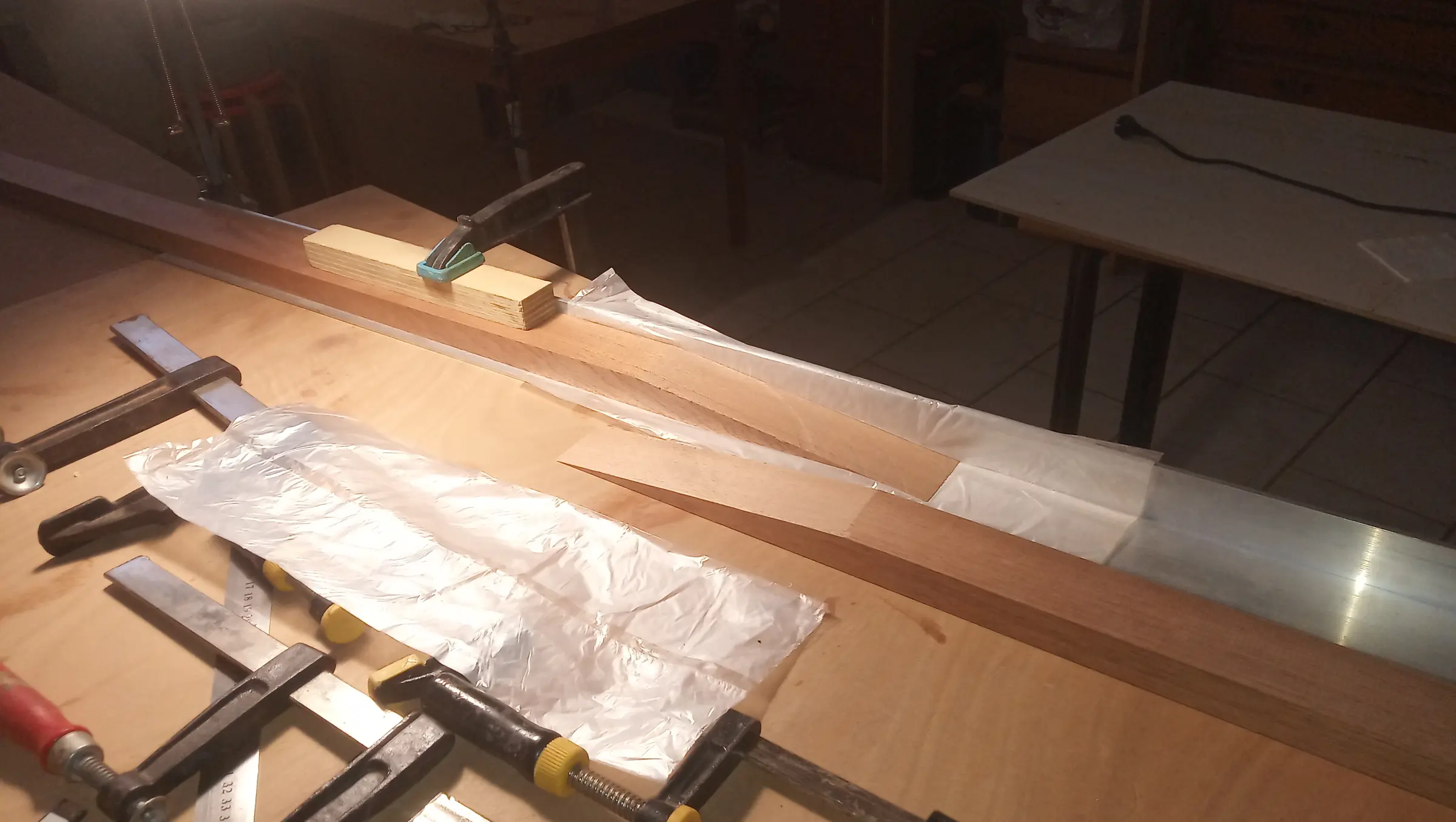
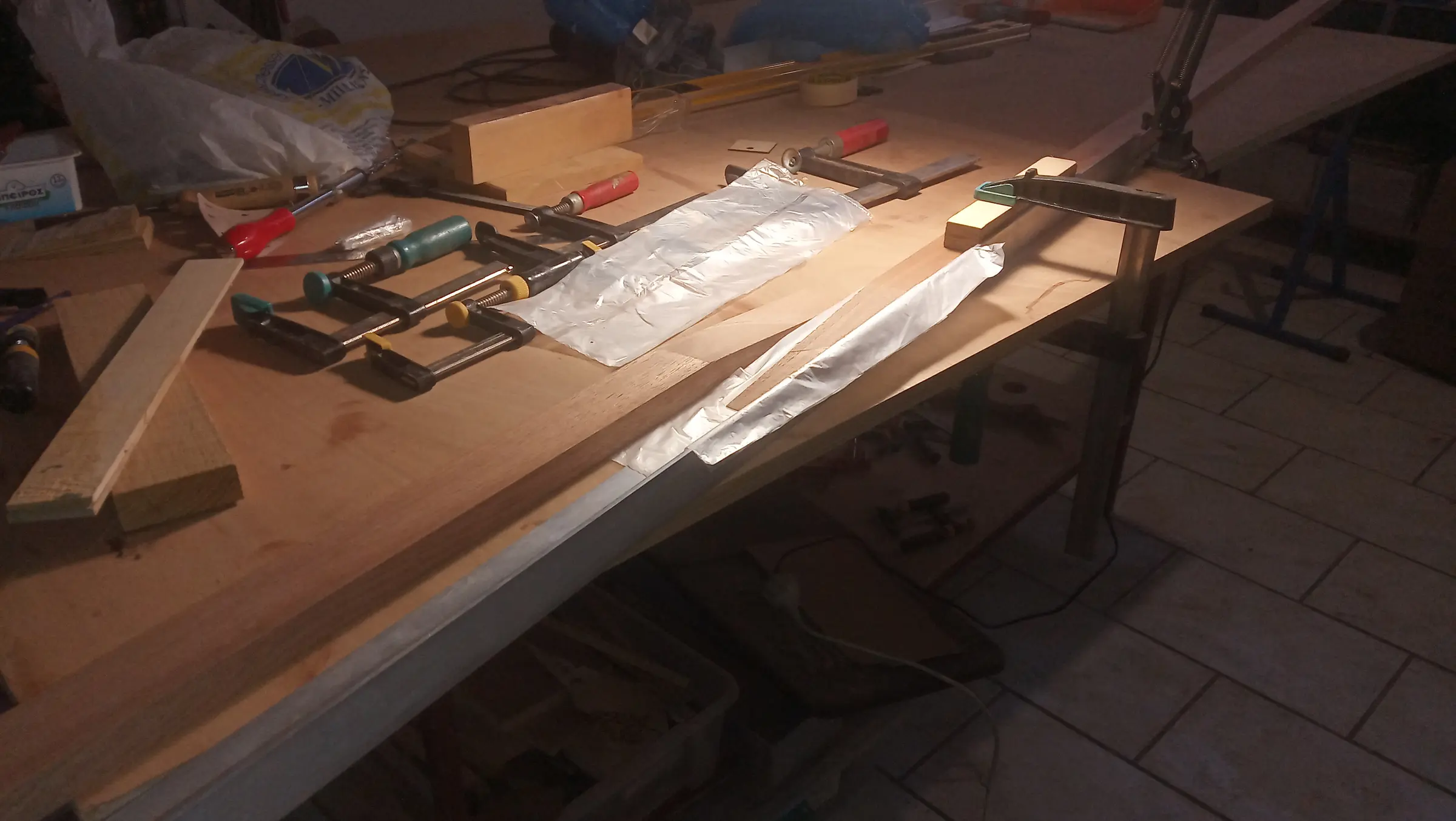
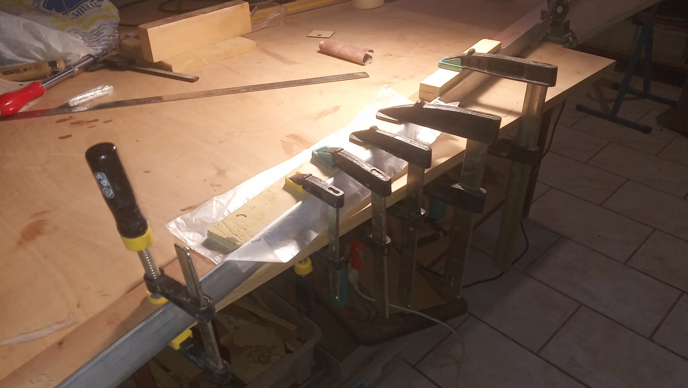
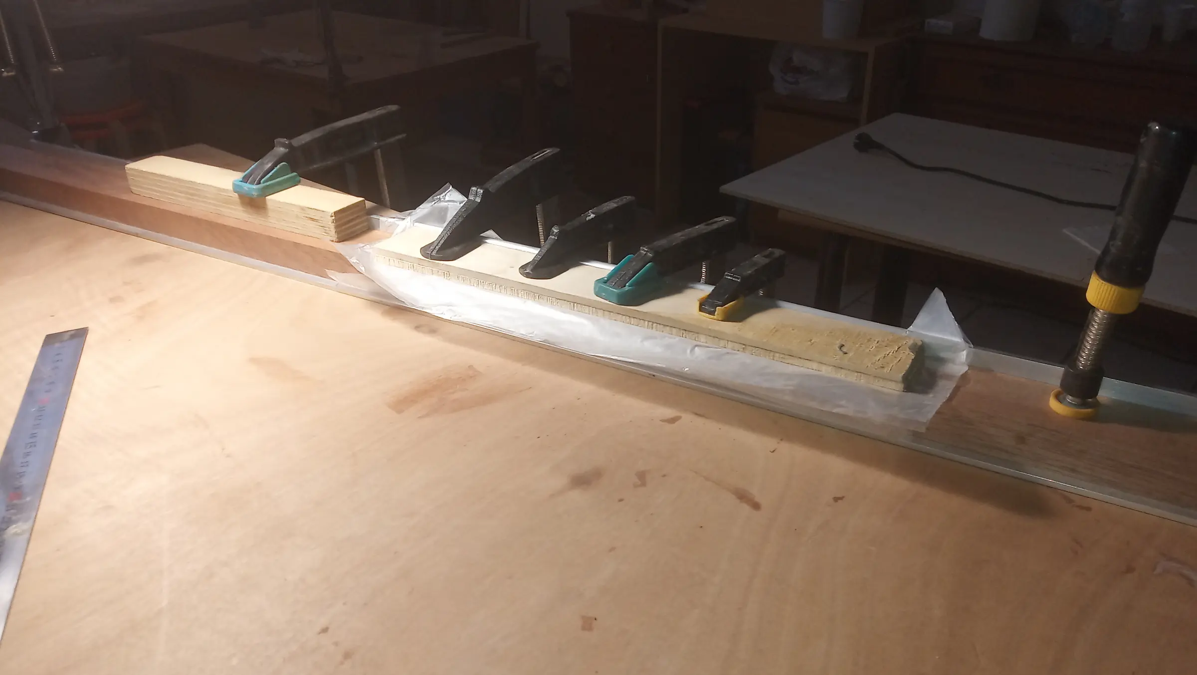
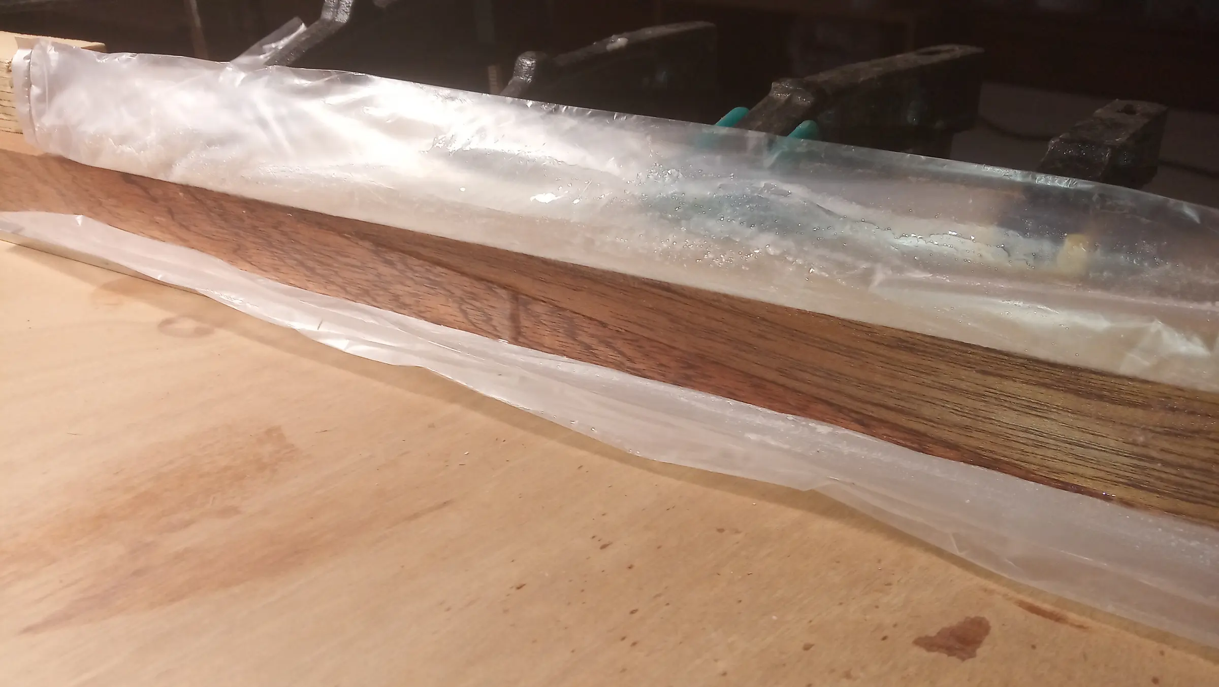
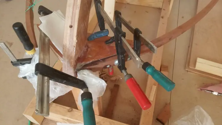
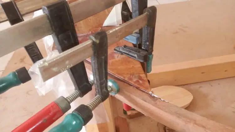
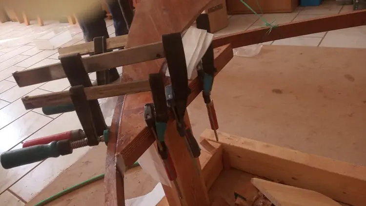
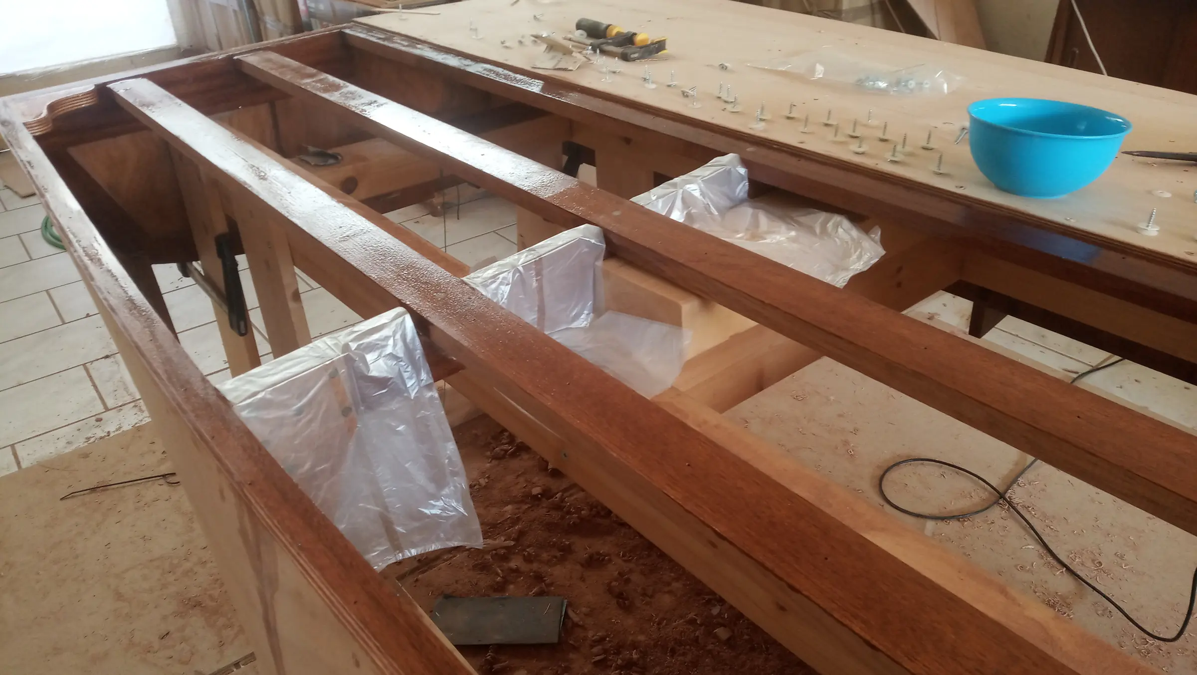
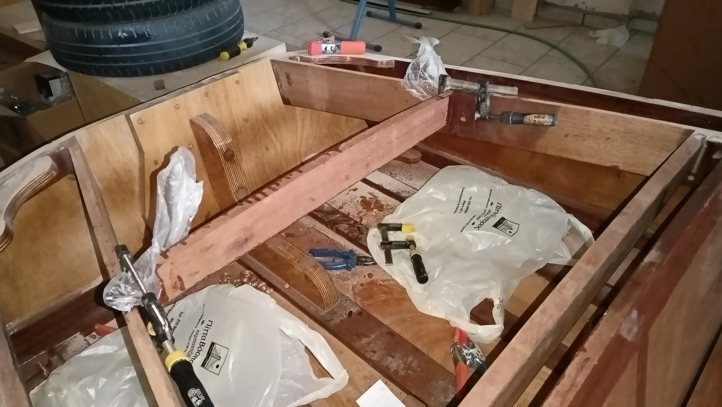
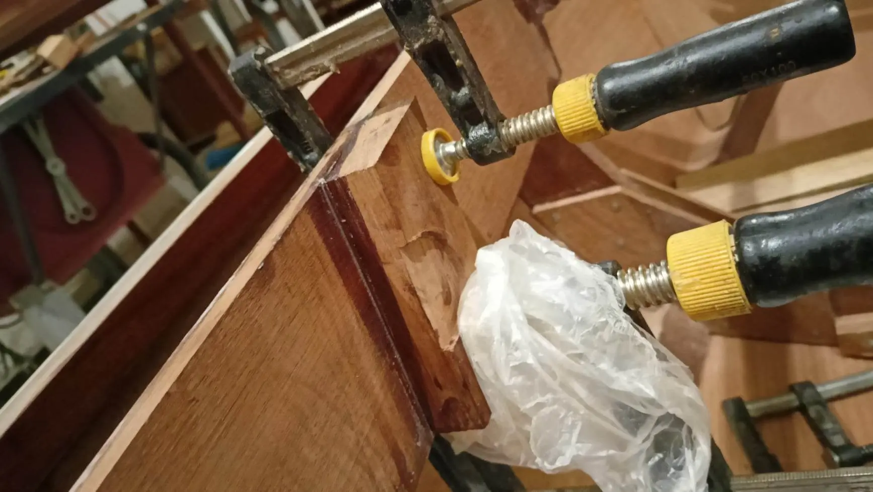
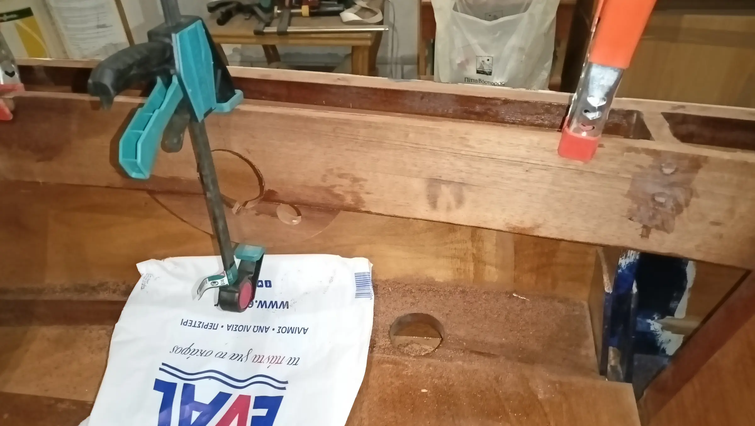
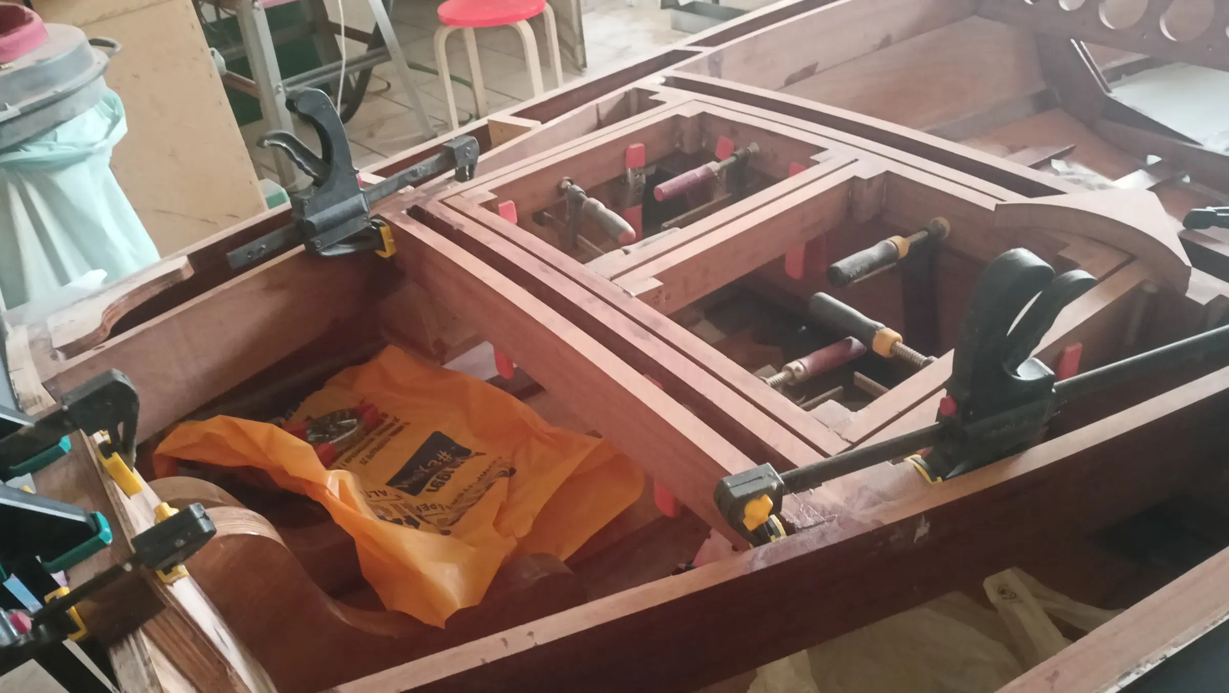
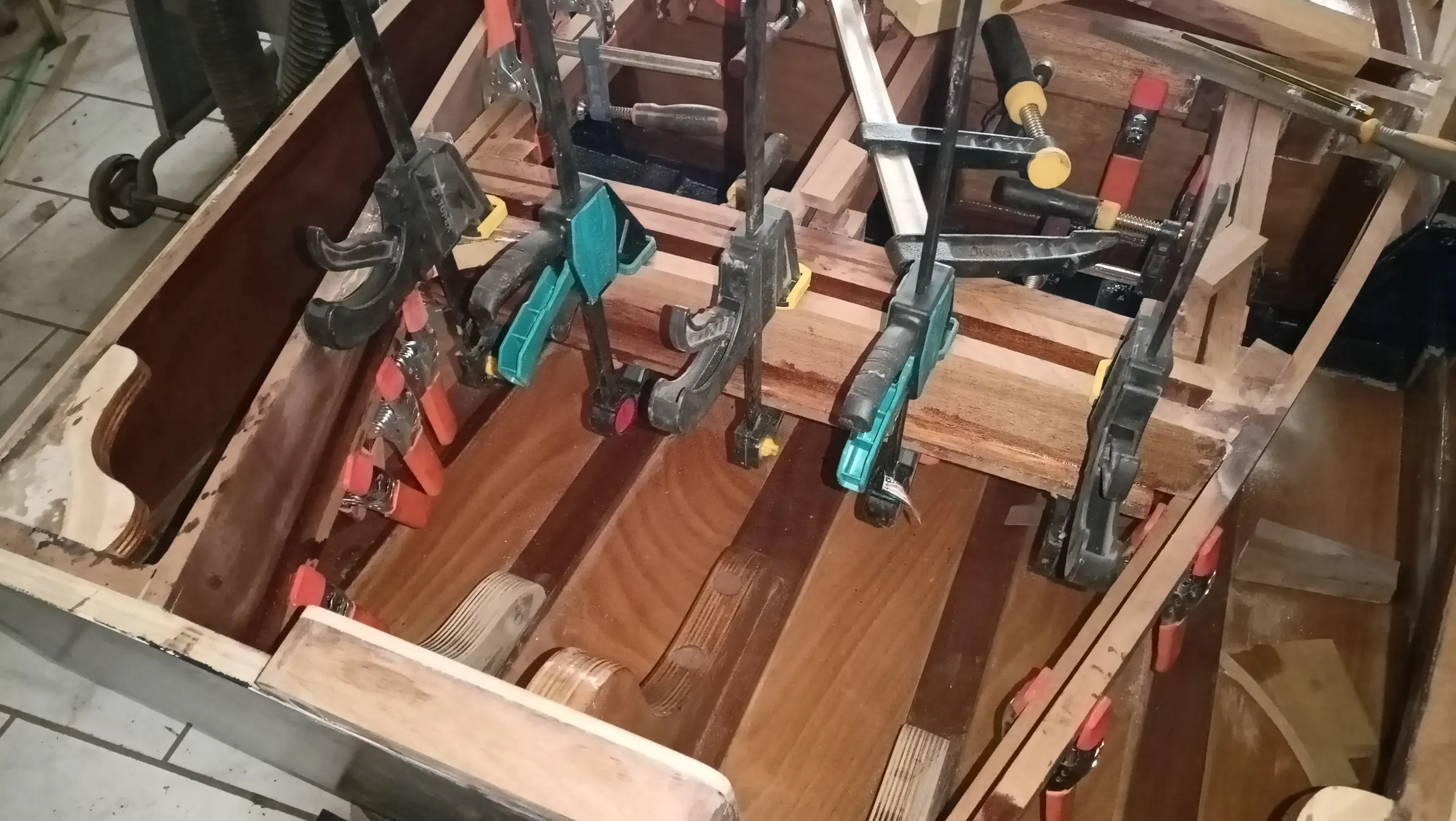
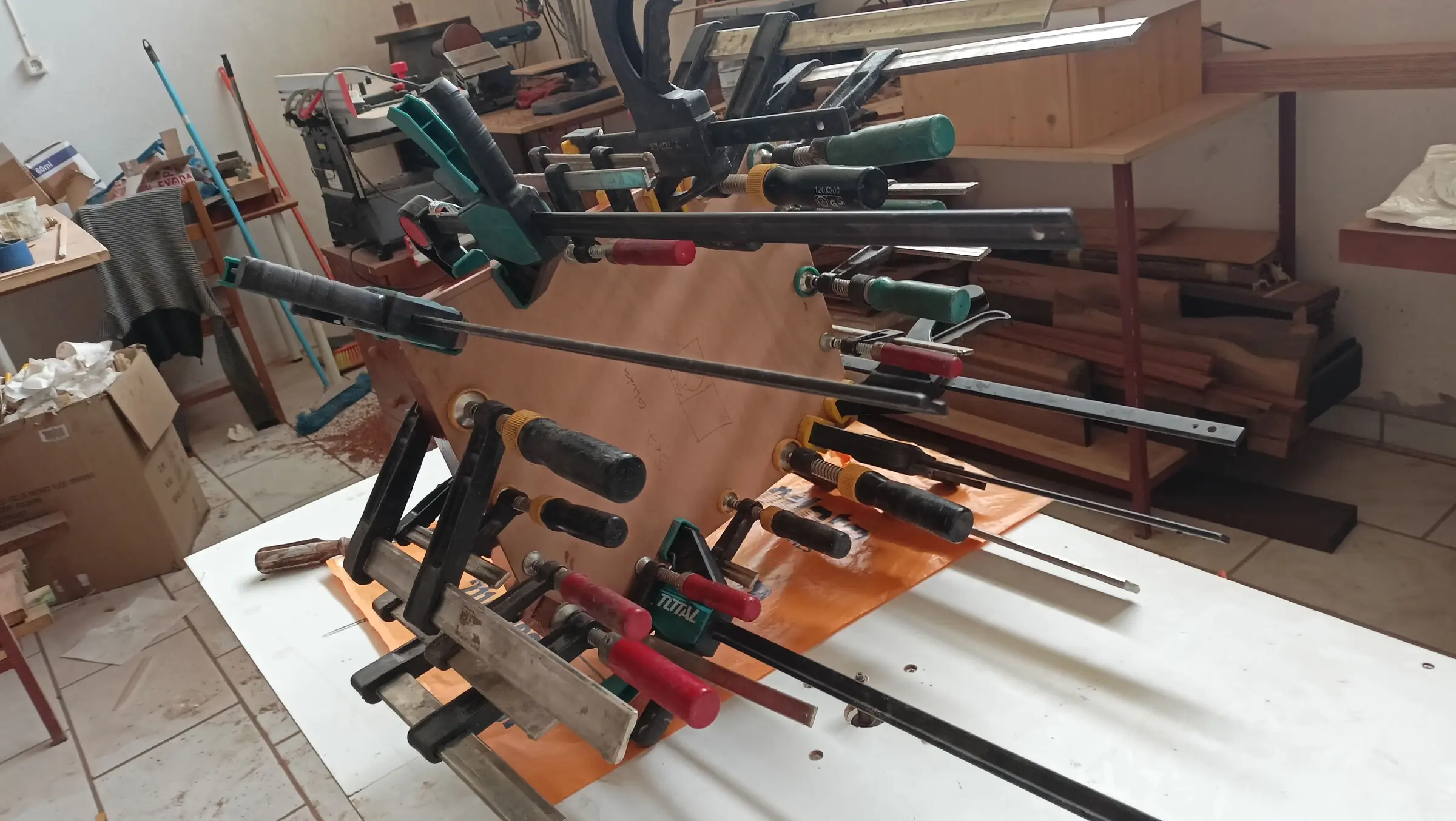
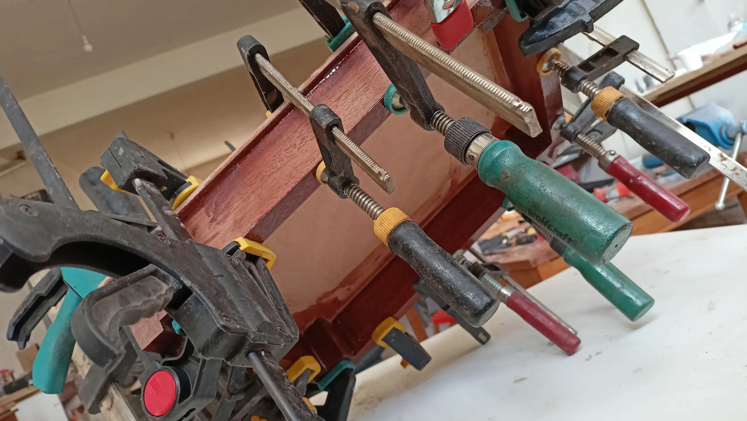
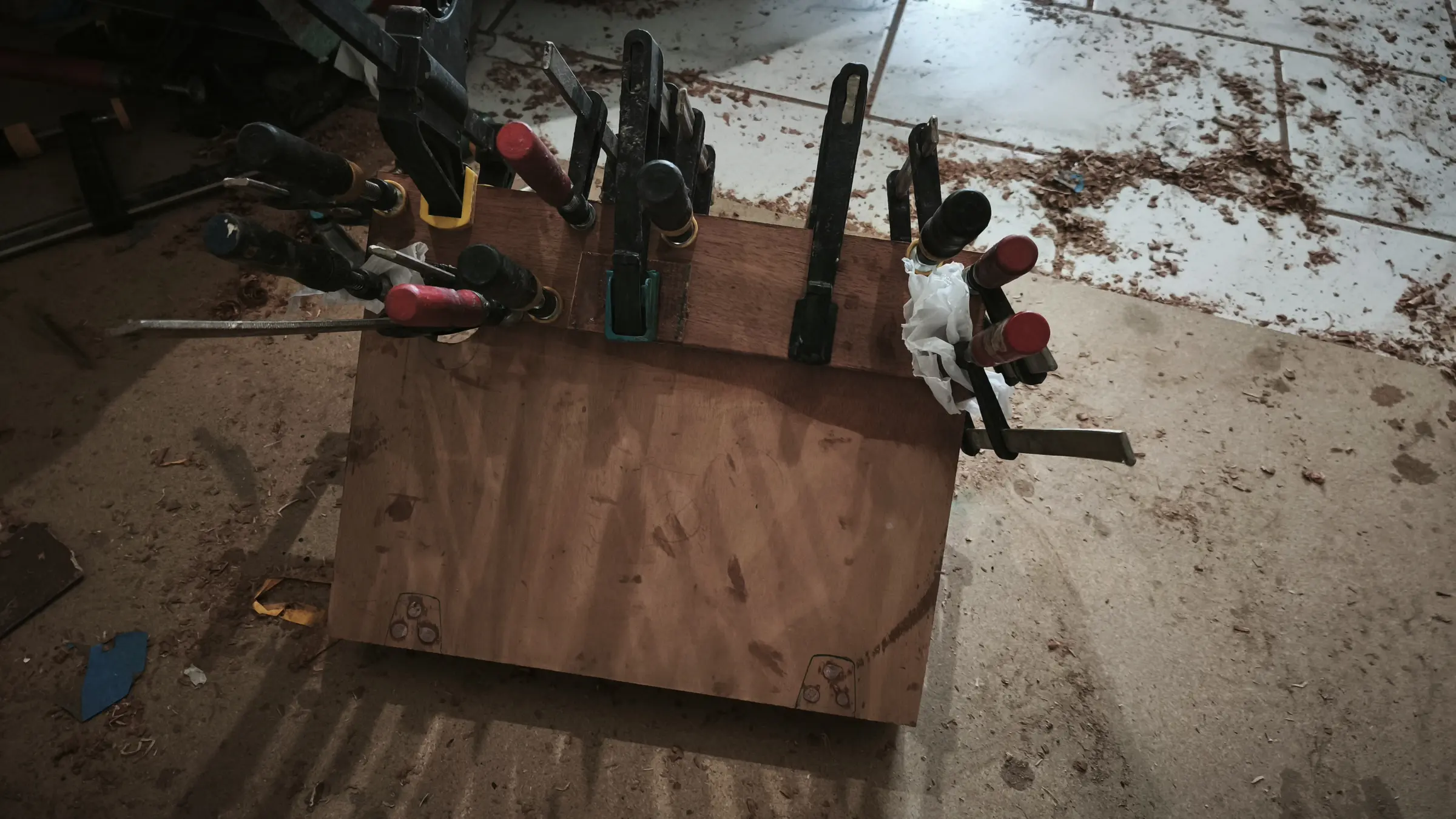
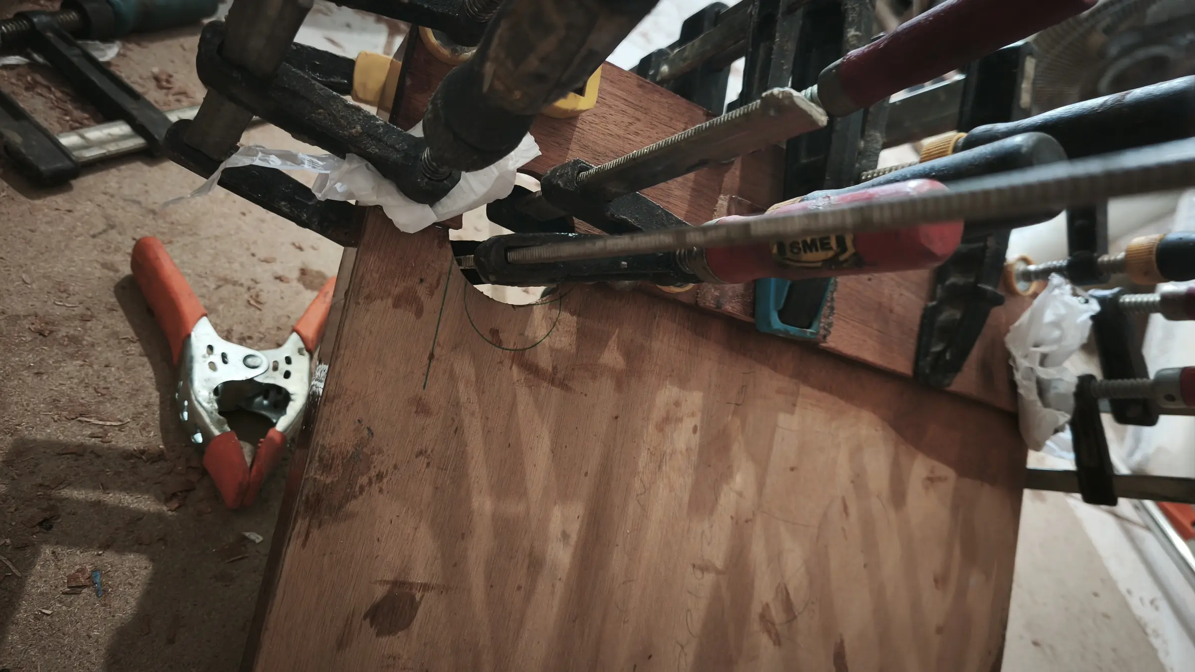
Some photographs of the work (gluing with epoxy, then screwing and nailing). The packaging bags are there because the material they are made of does not stick to resin, so I do not have to worry about the clamps gluing themselves to the timber. To make sure I did not drift away from the plans or lose symmetry, I printed the drawings full size at 1:1 and did all the glue-ups directly on top of them. That could not be done with the transom, because it is a single piece of plywood. There the shape was traced across with carbon paper.

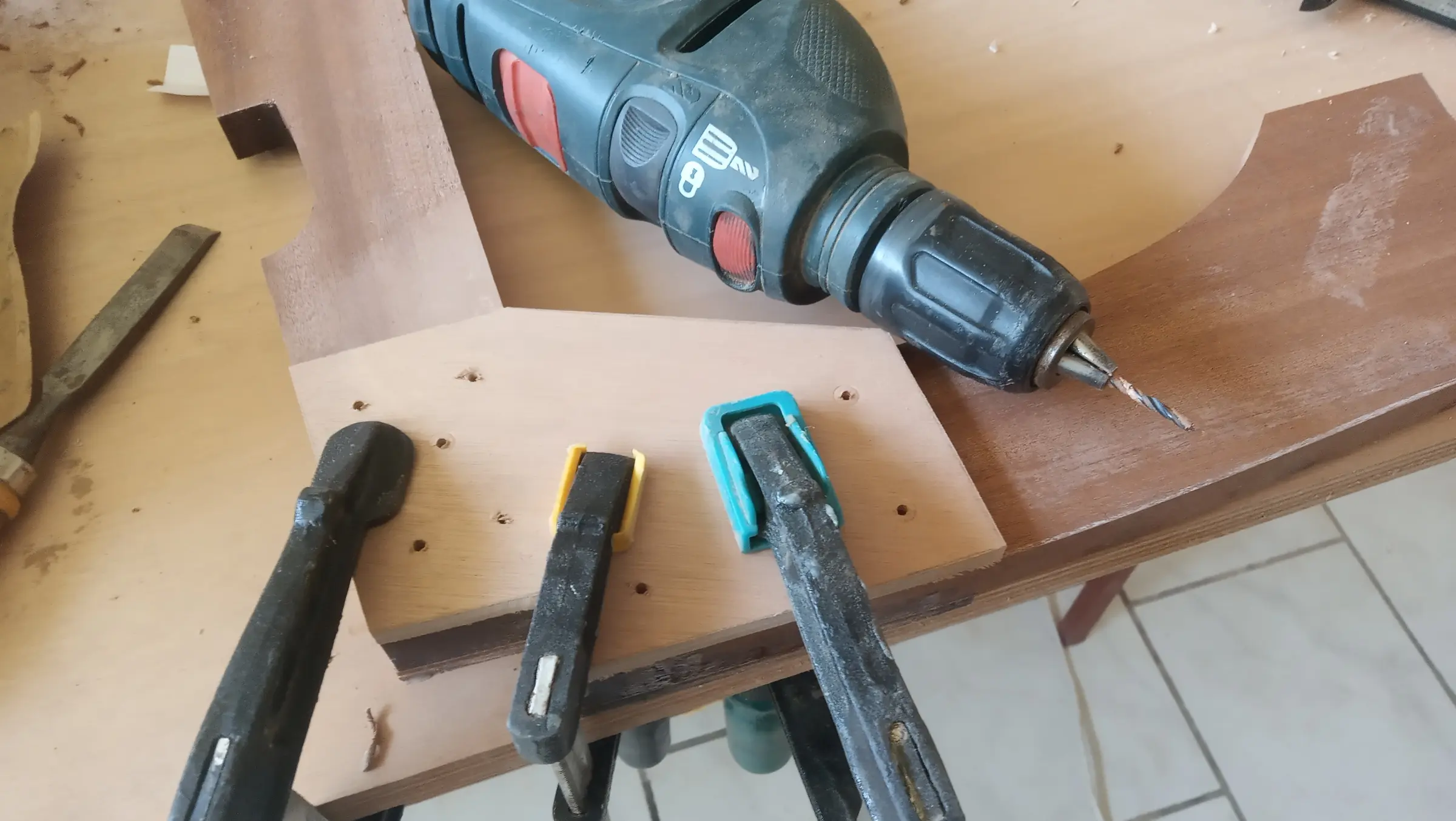
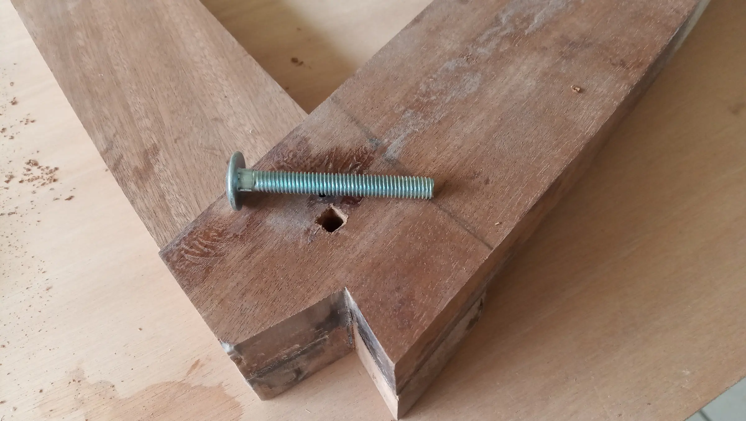
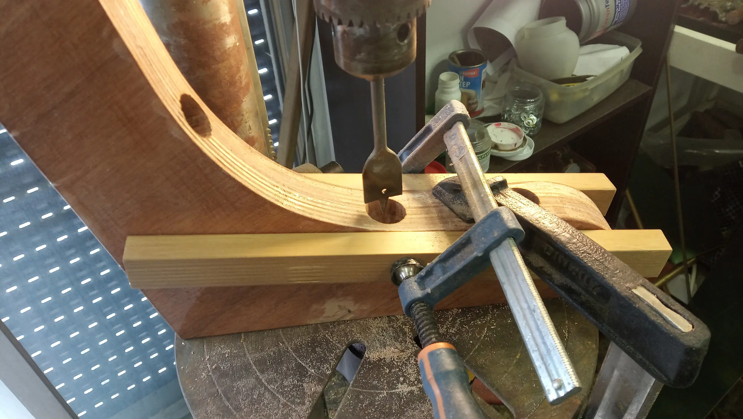
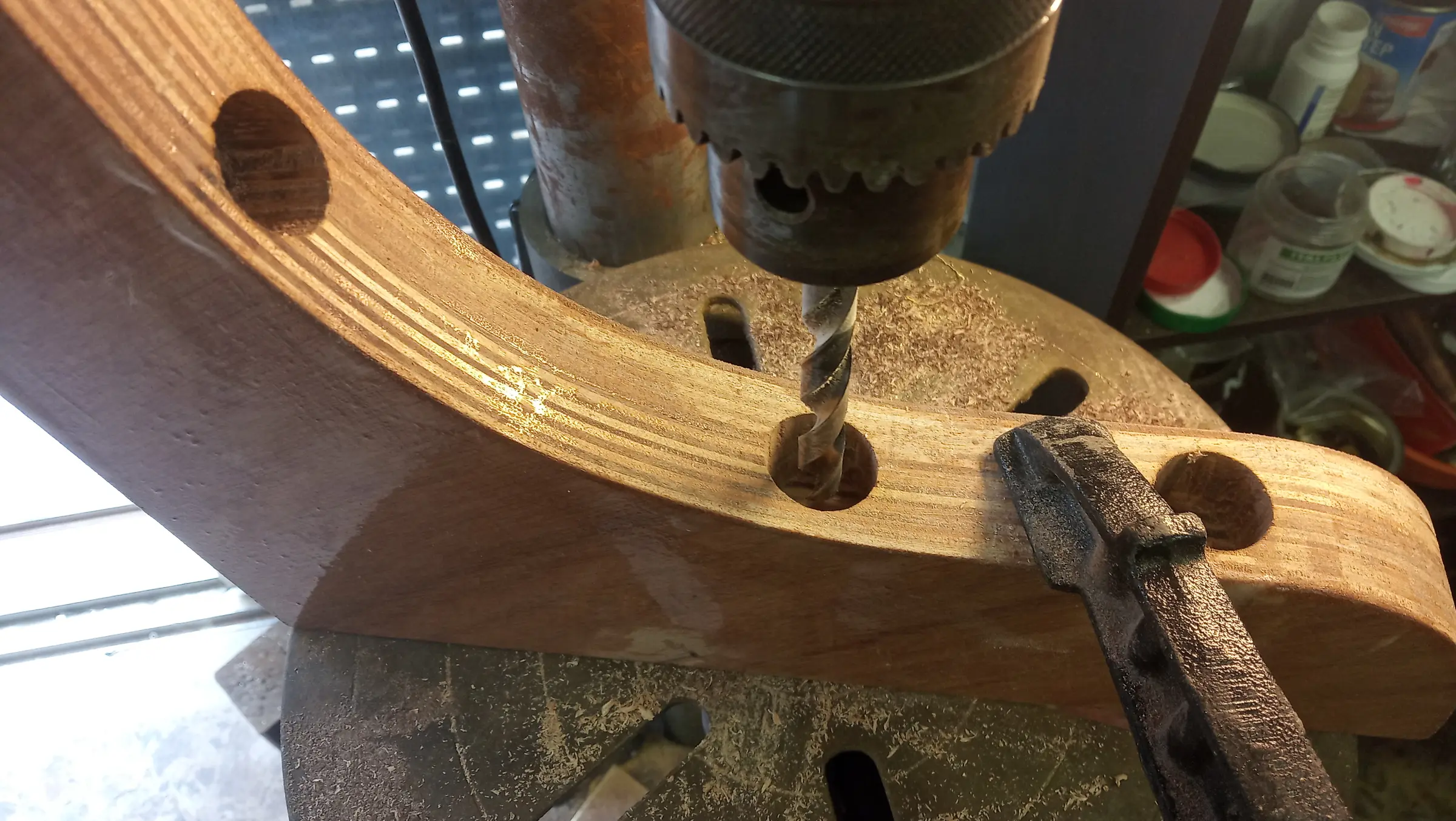
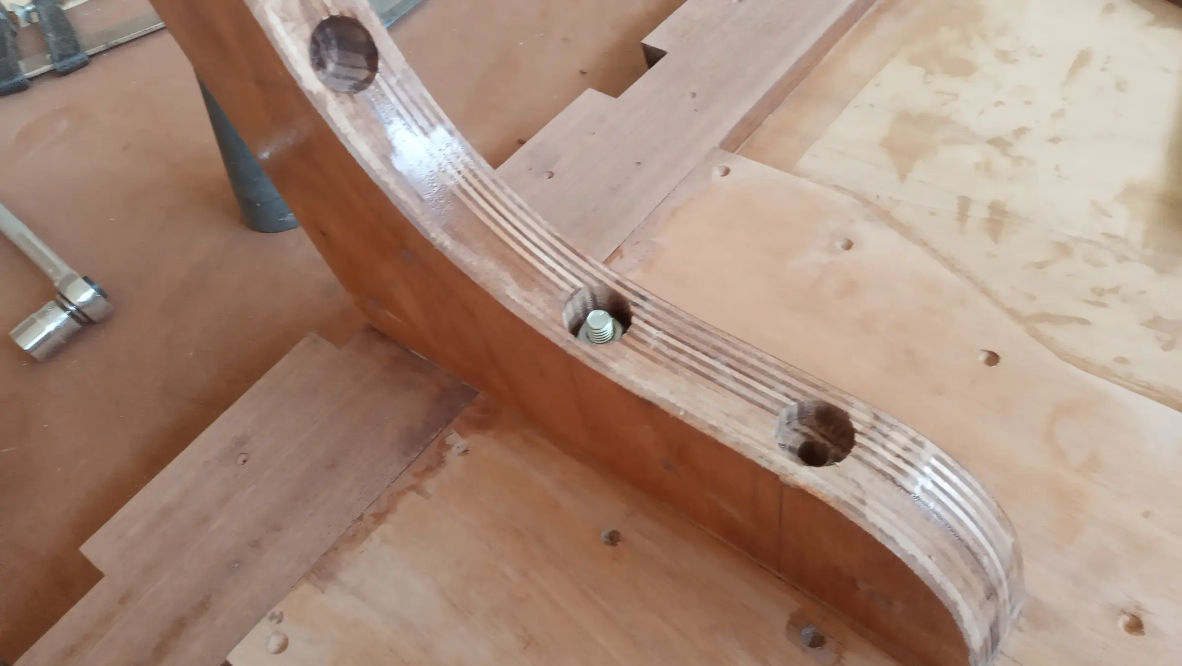
Next, the holes were drilled for the 10 mm galvanised carriage bolts in the transom knee. First the large holes with a 25 mm spade bit, for the nut and the socket that would tighten it, then drilled through with a 10 mm bit for the bolt itself.

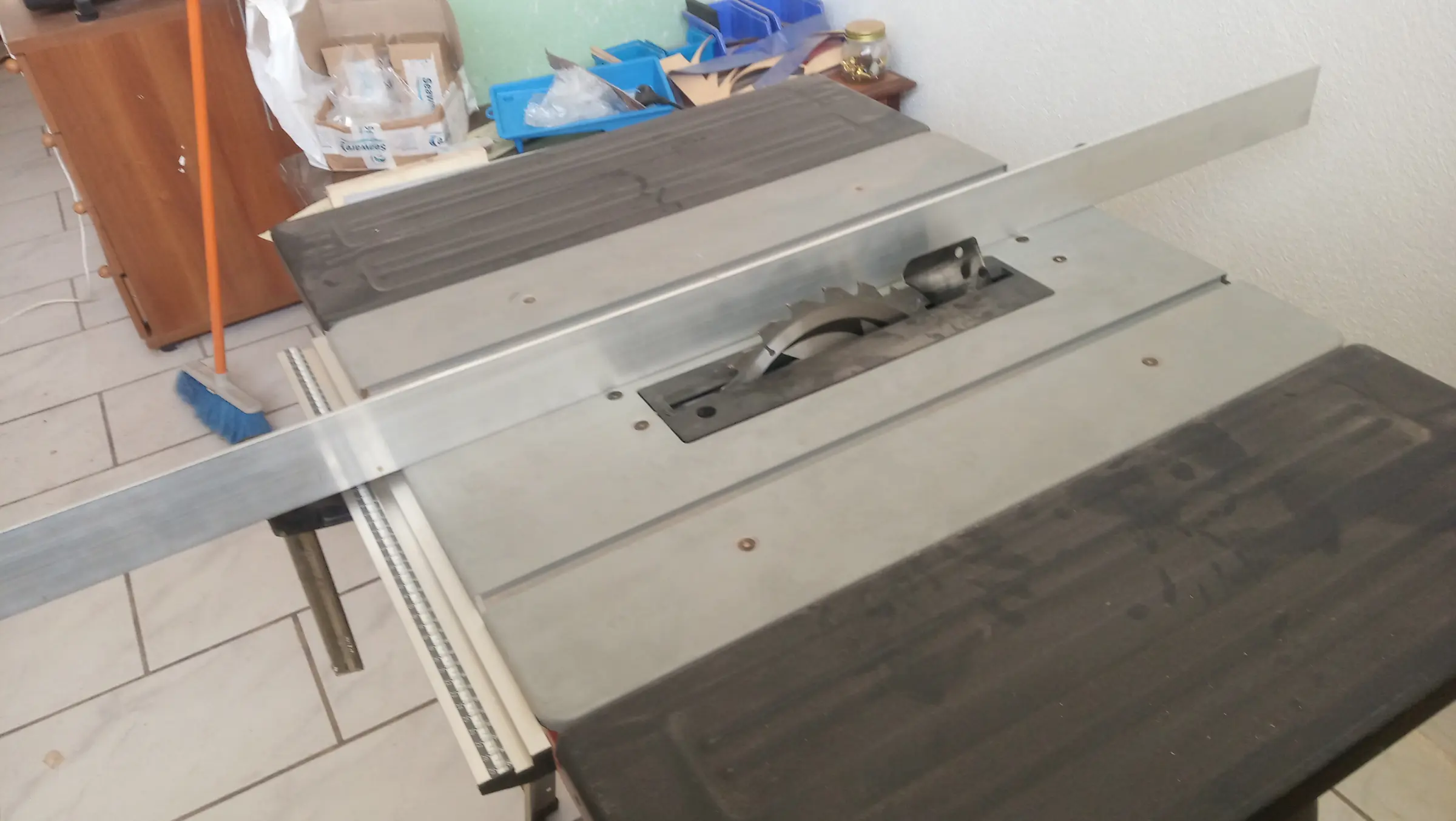
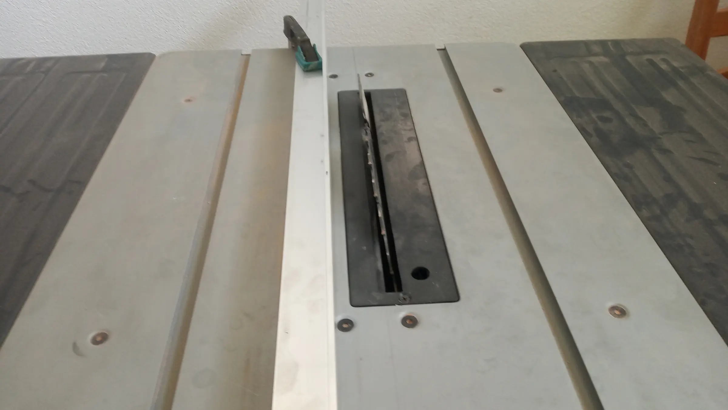
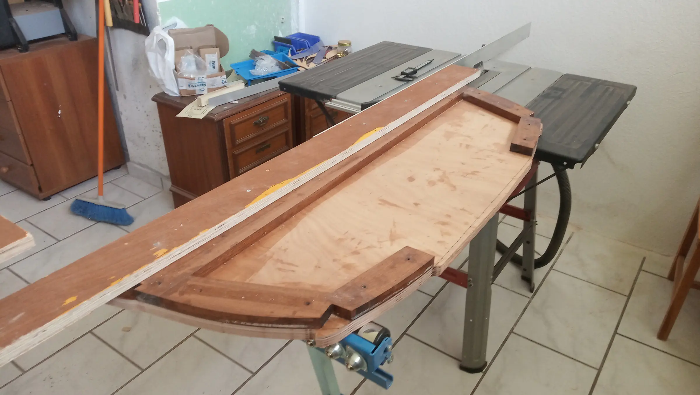
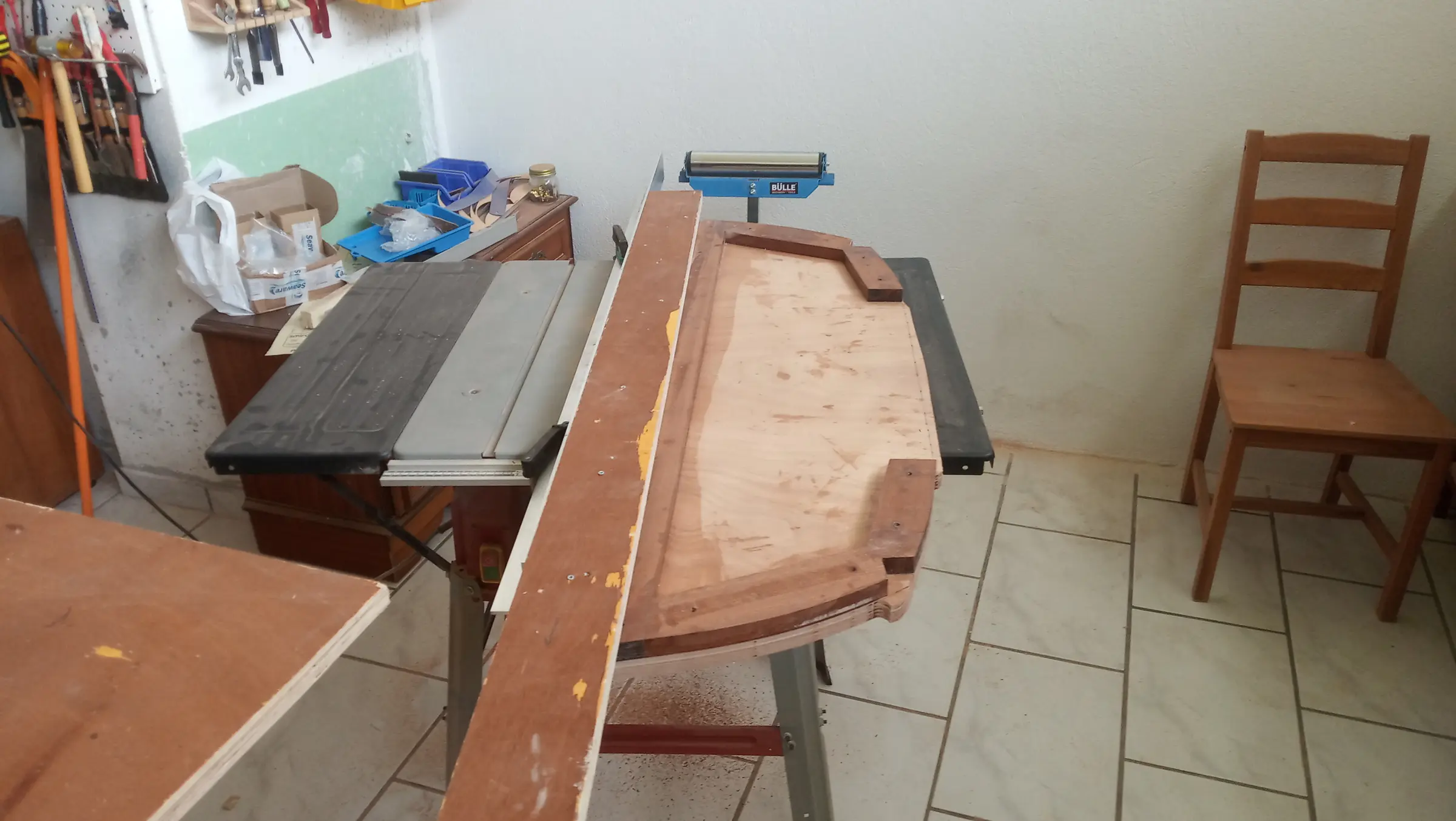
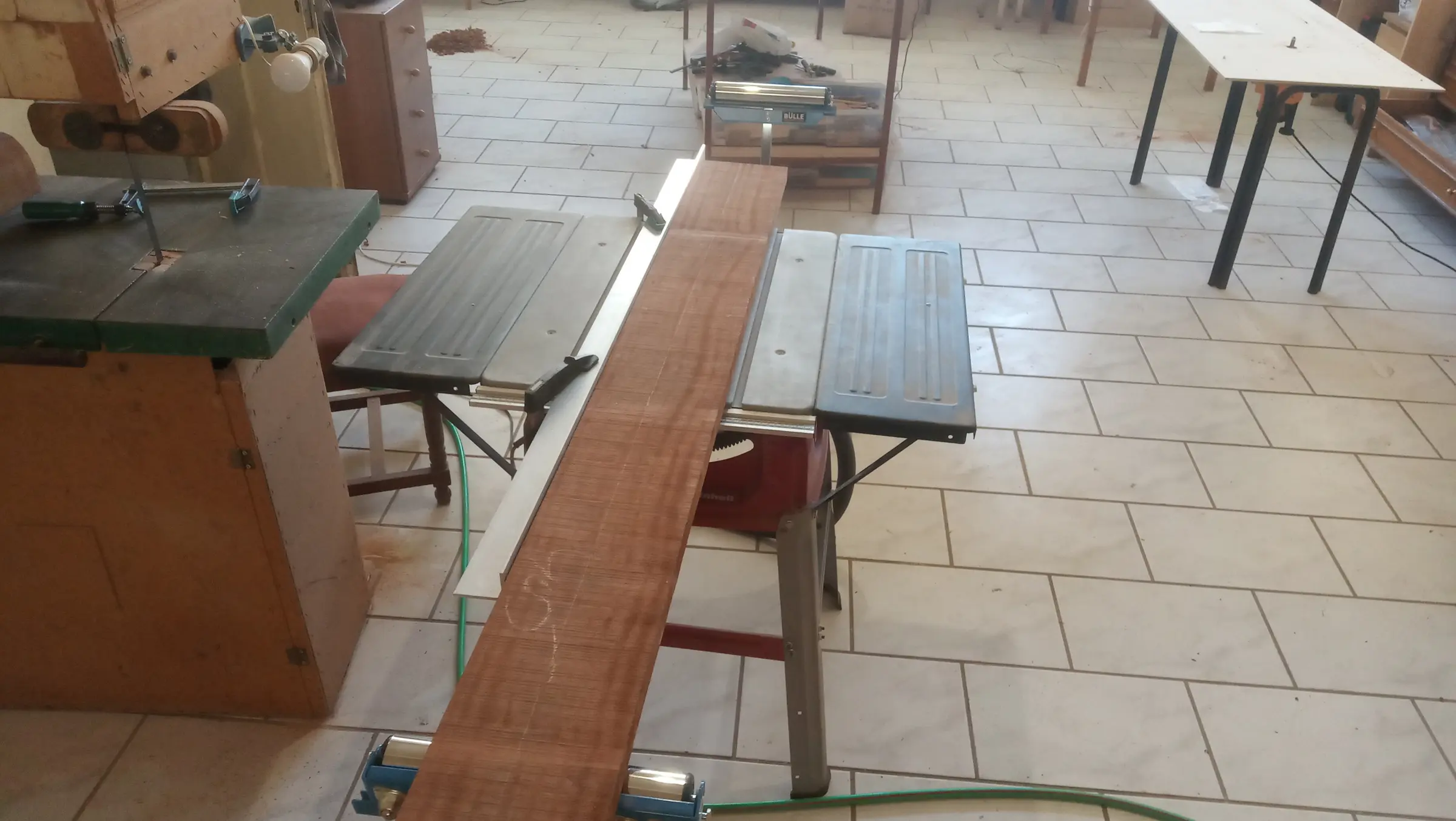
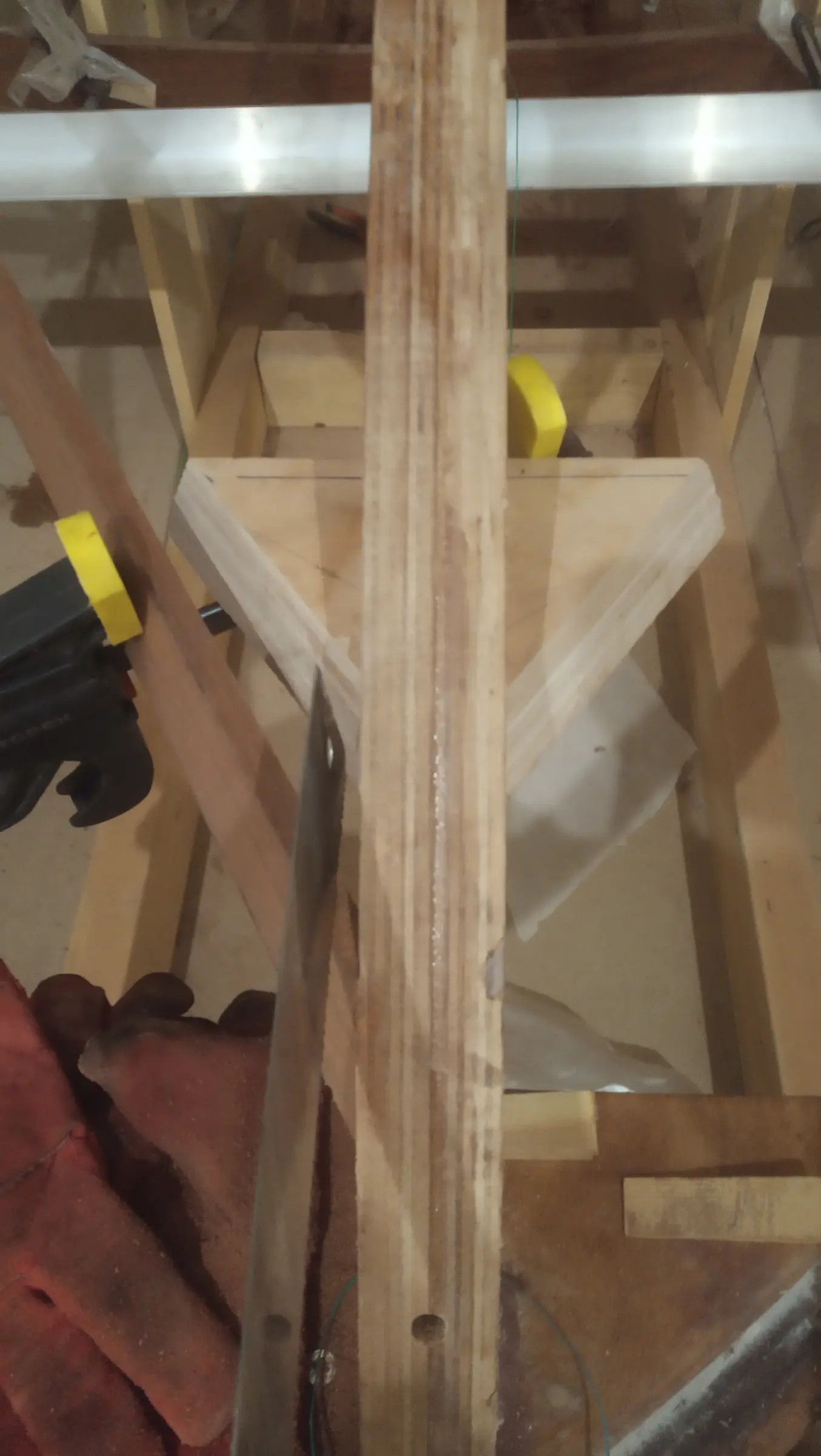
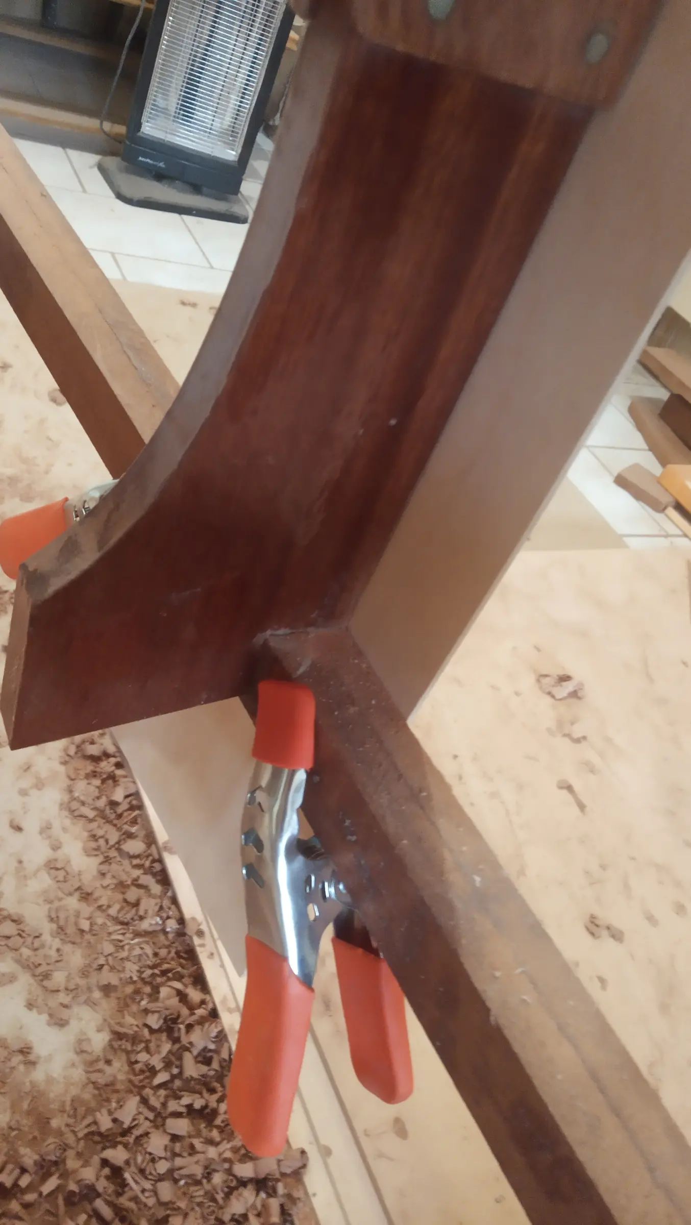
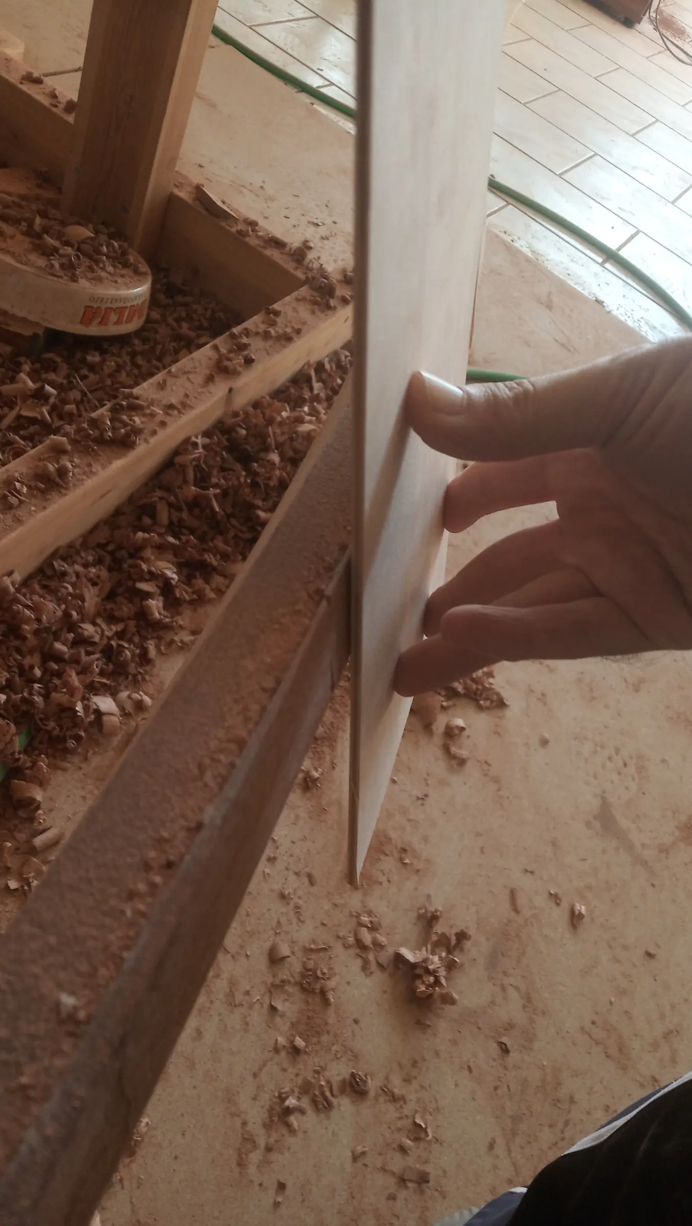
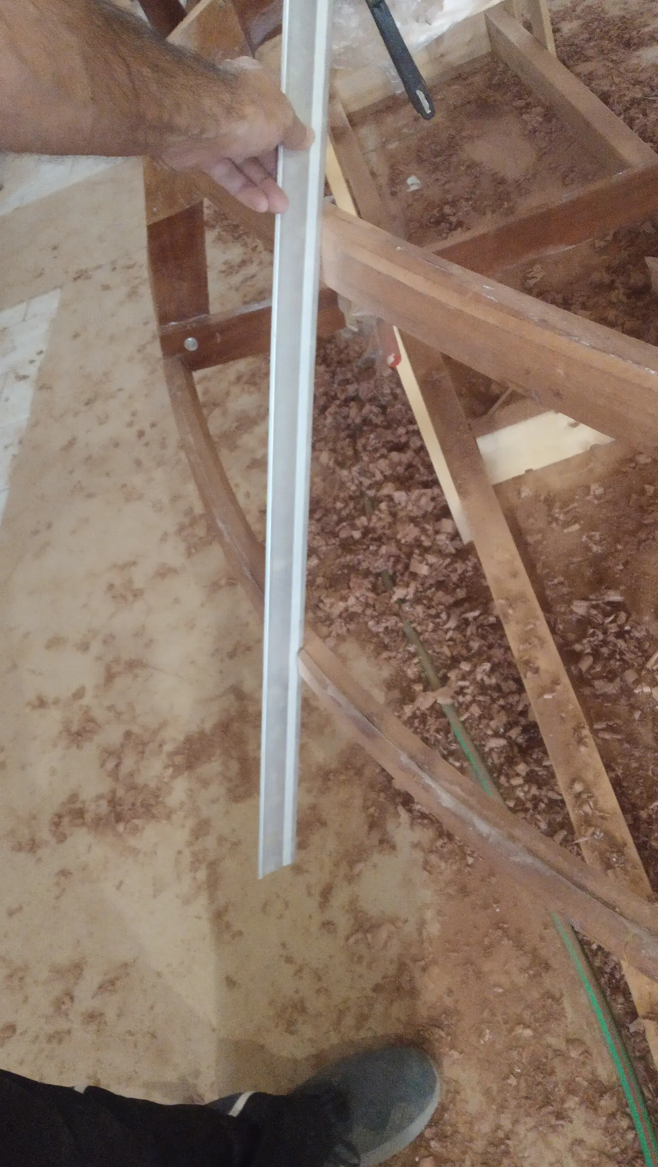
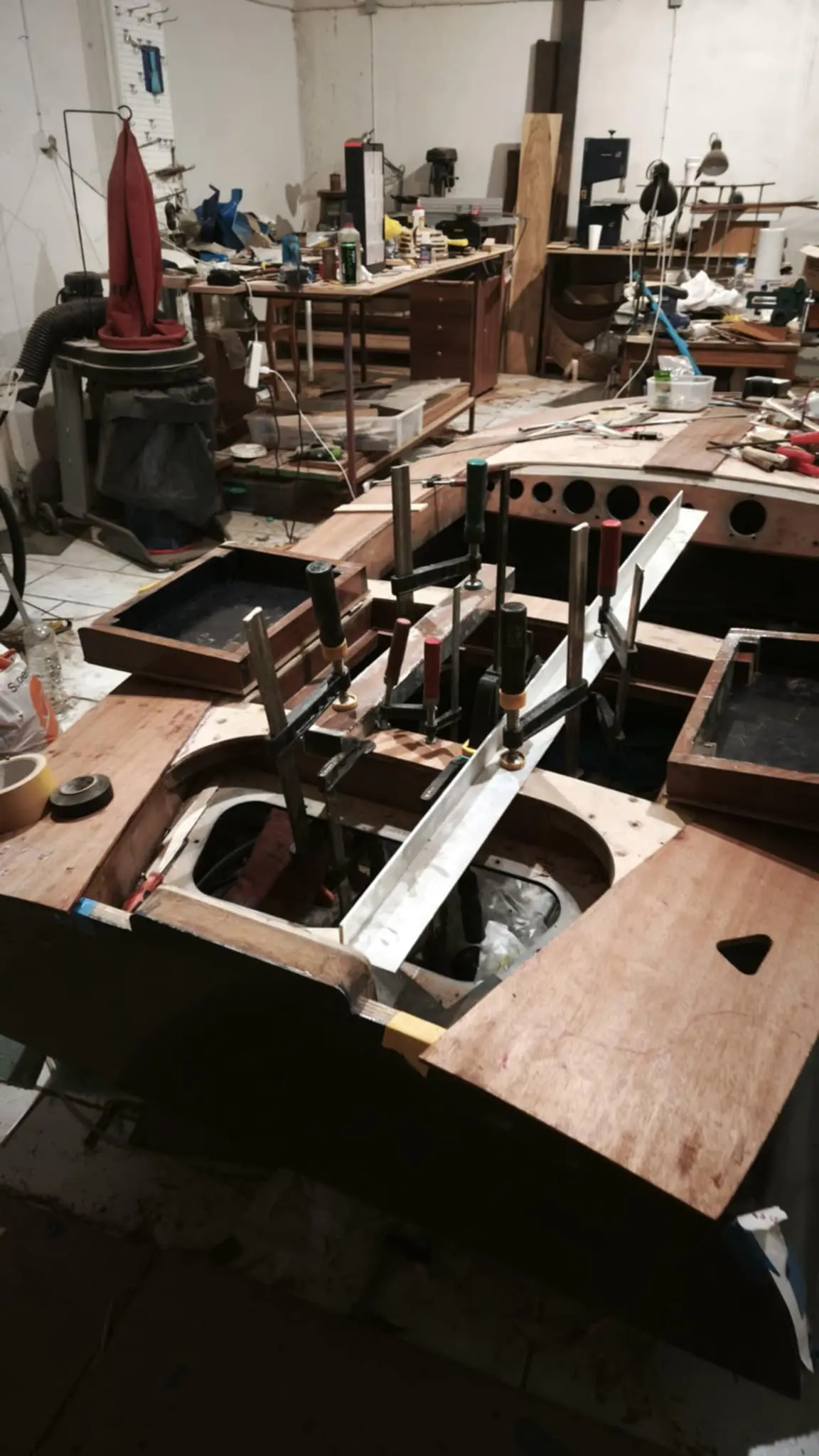
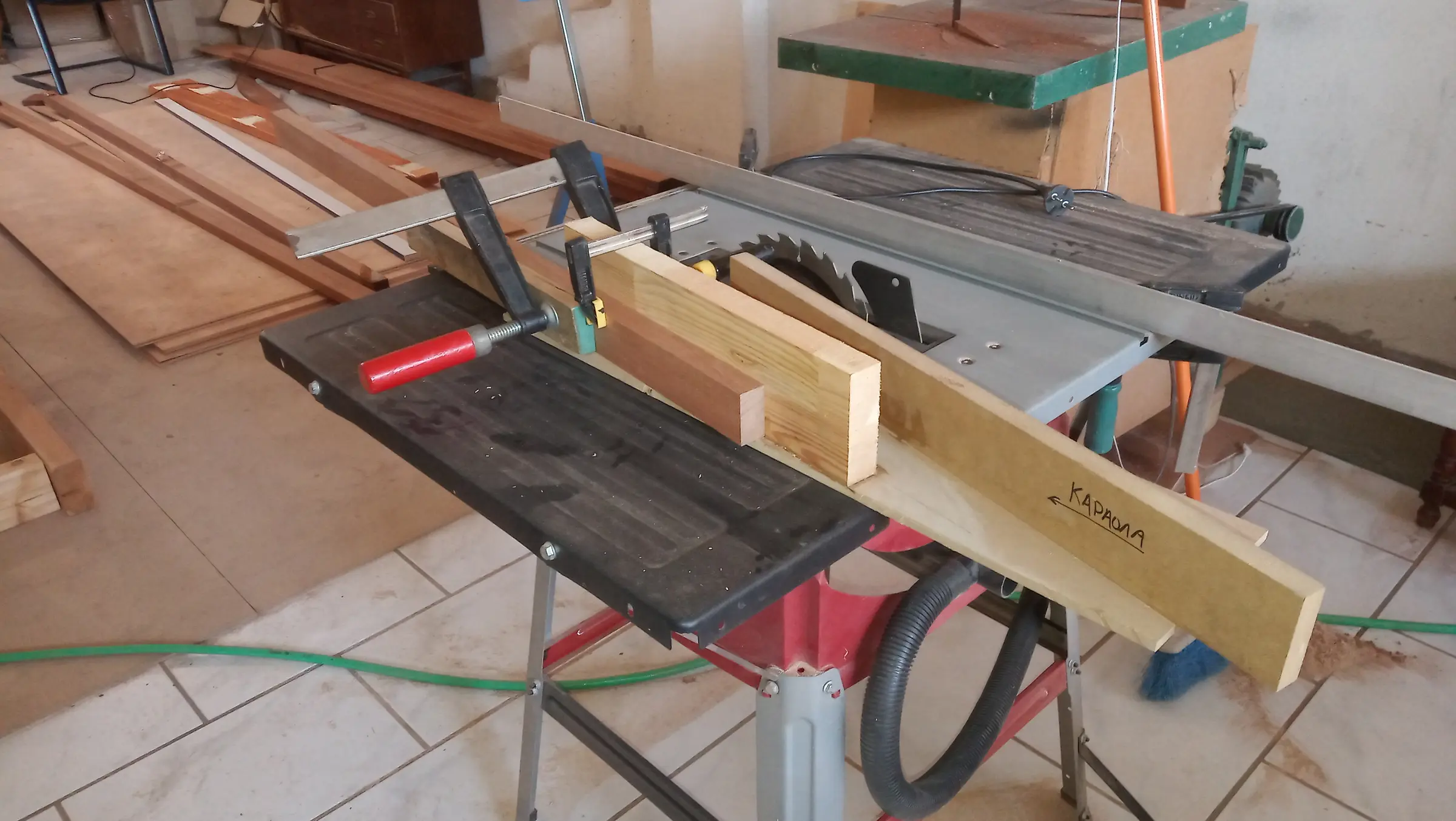
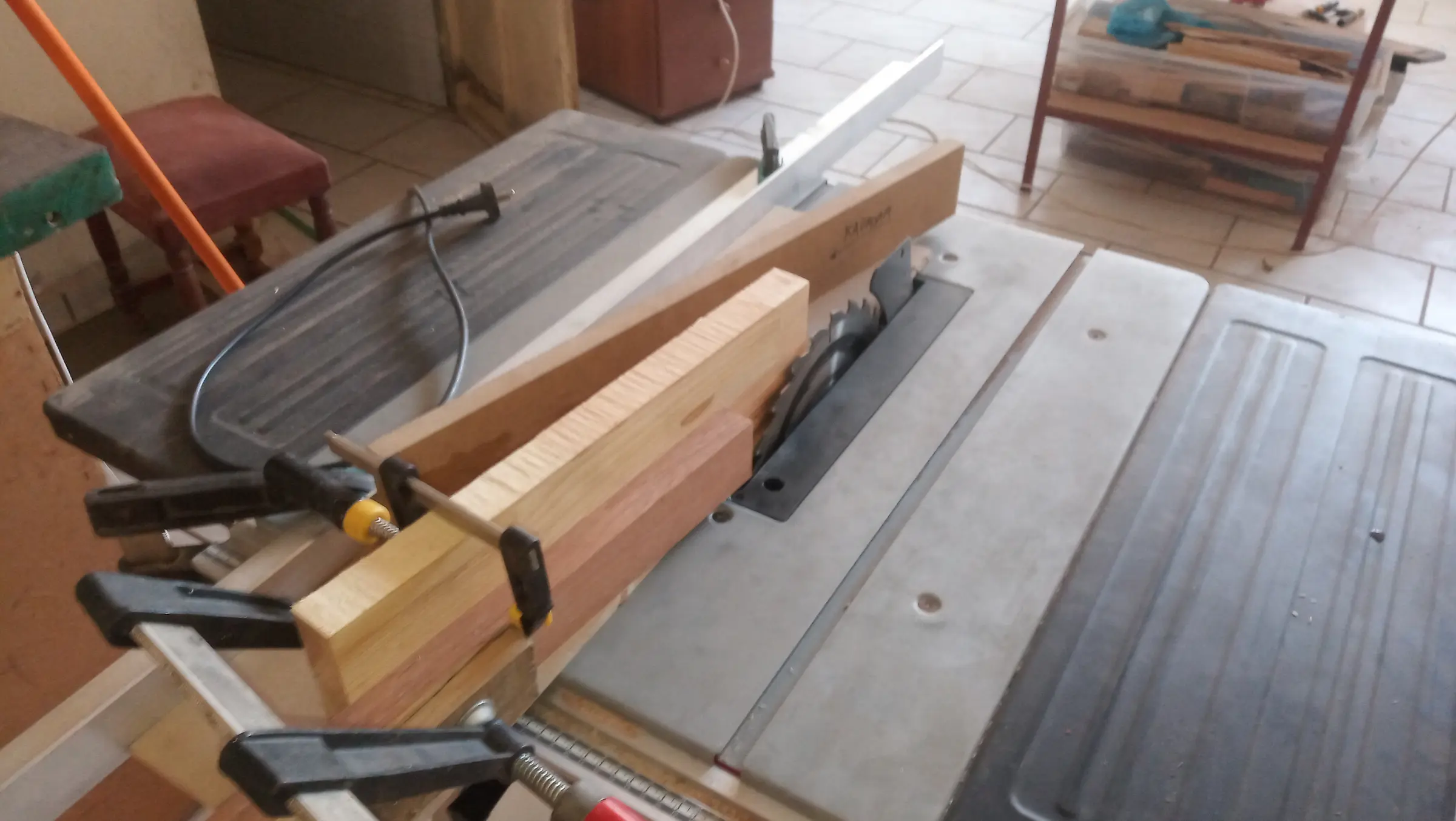
The next job was cutting the bottom edge of the transom to a 12 degree angle. I bought an aluminium angle to use as a fence on the table saw. The angle was set and a sacrificial guide batten was screwed to the transom, parallel to its edges, so it could follow the line of the aluminium. The batten and the aluminium had to be set up twice, because the transom is not straight across but a very shallow V.

Then, in the same way as the transom bolts, holes were drilled for the carriage bolts that reinforce the joint between the two halves of the keel at the frame.

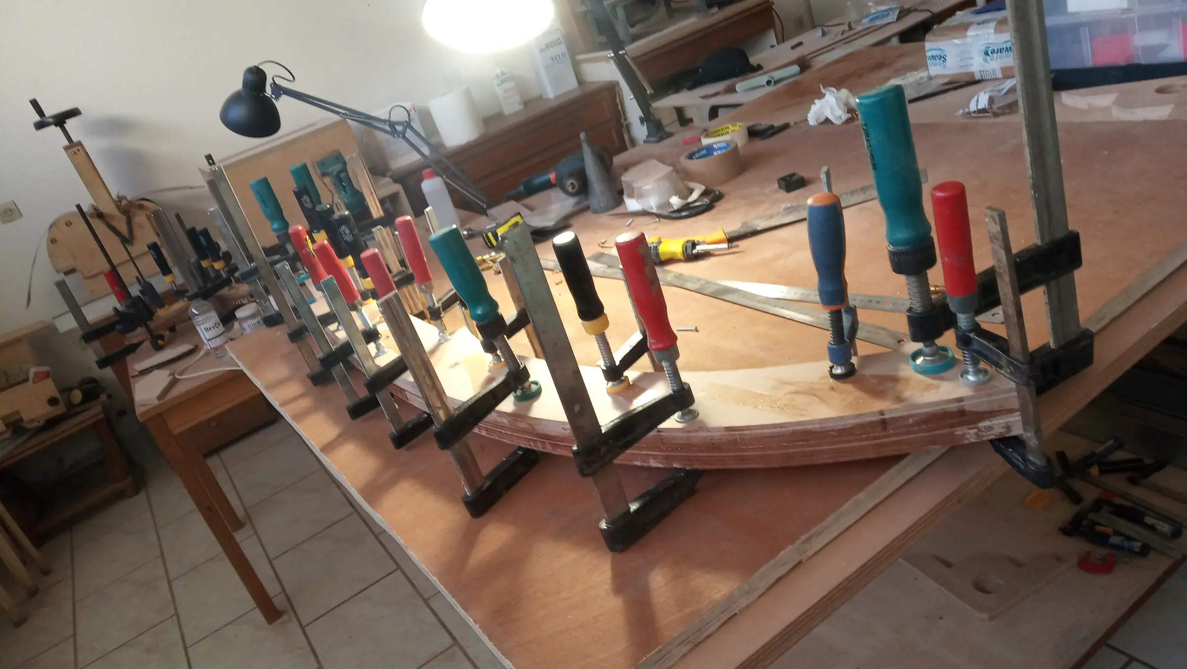
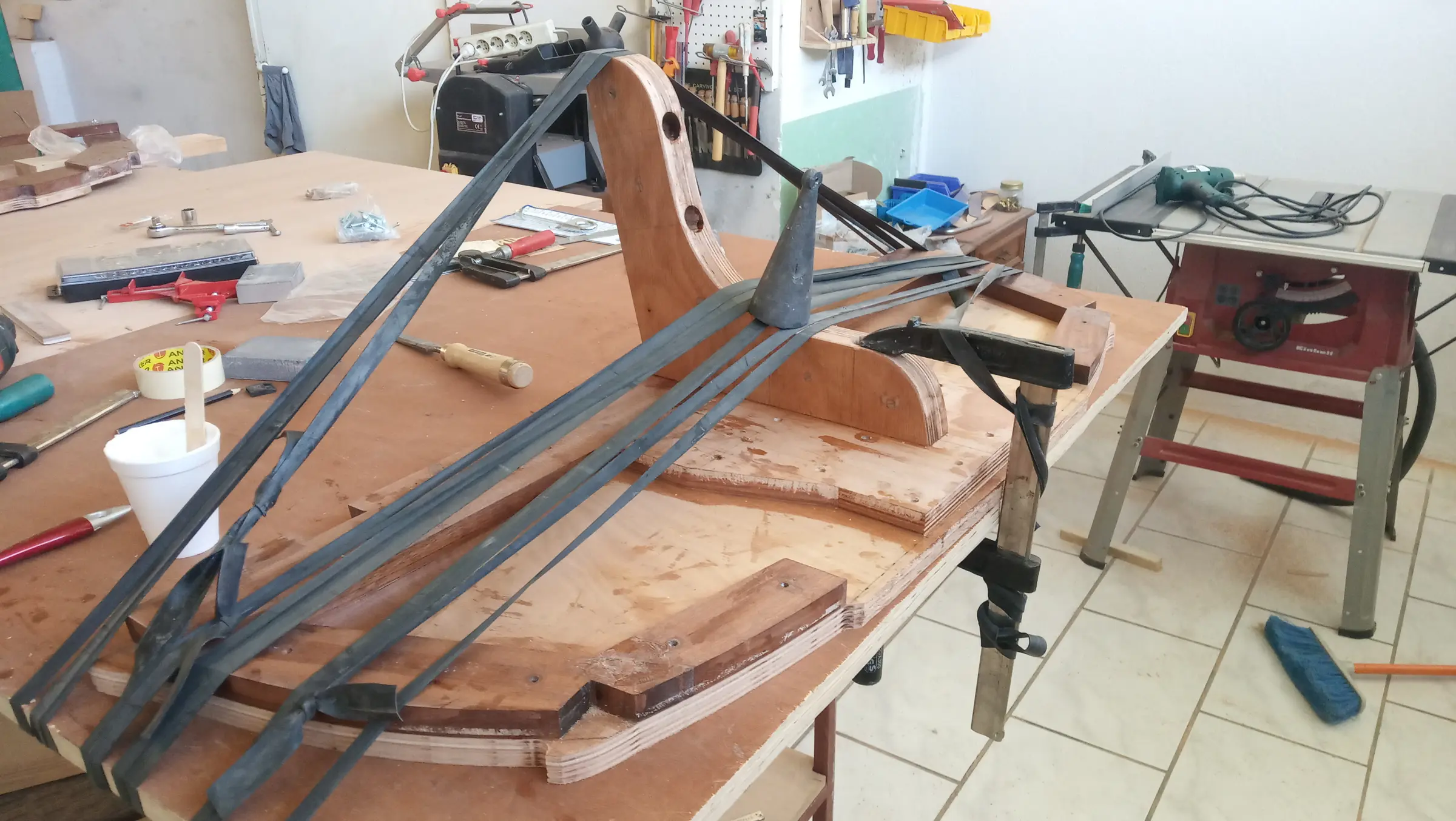
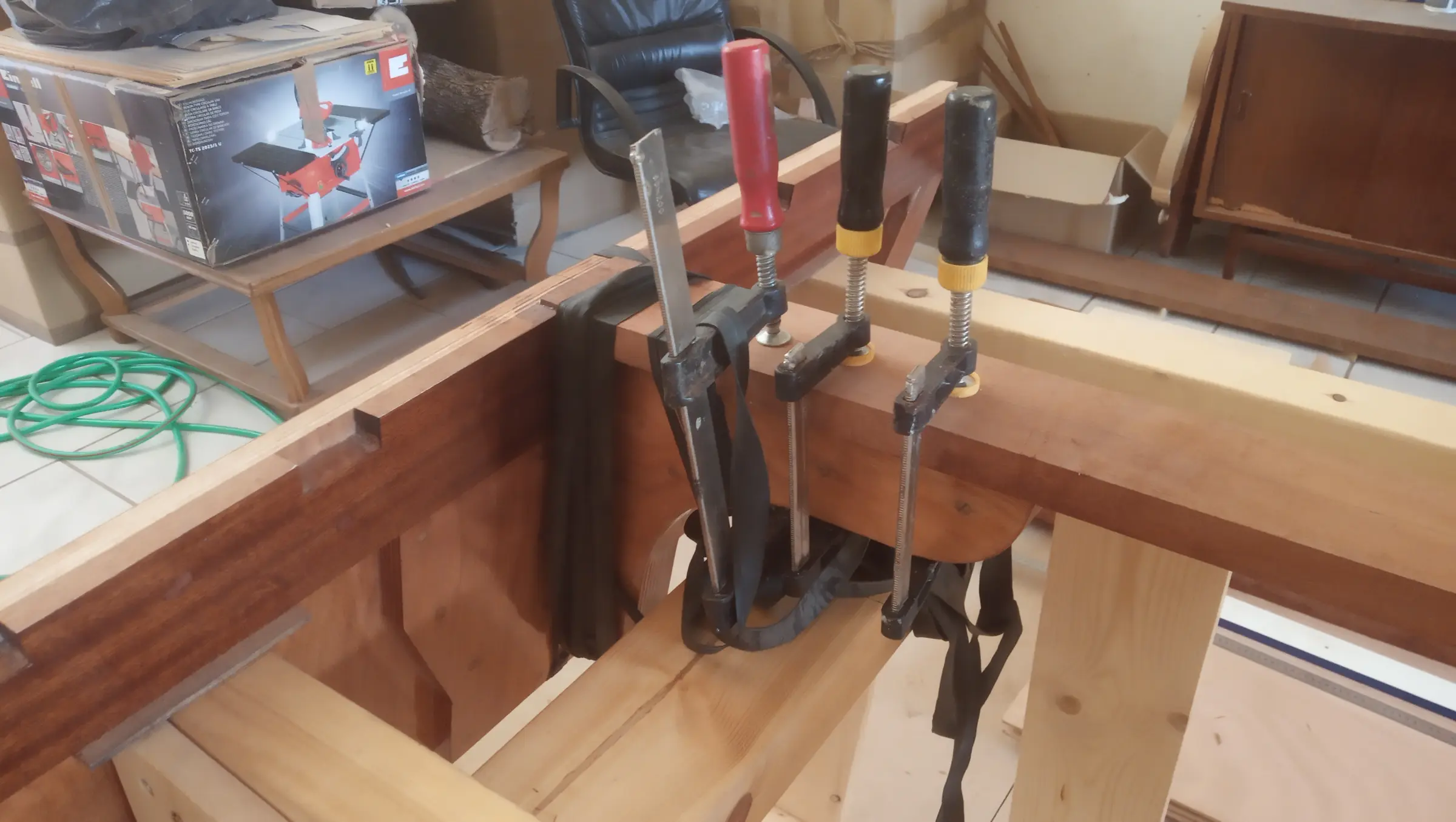
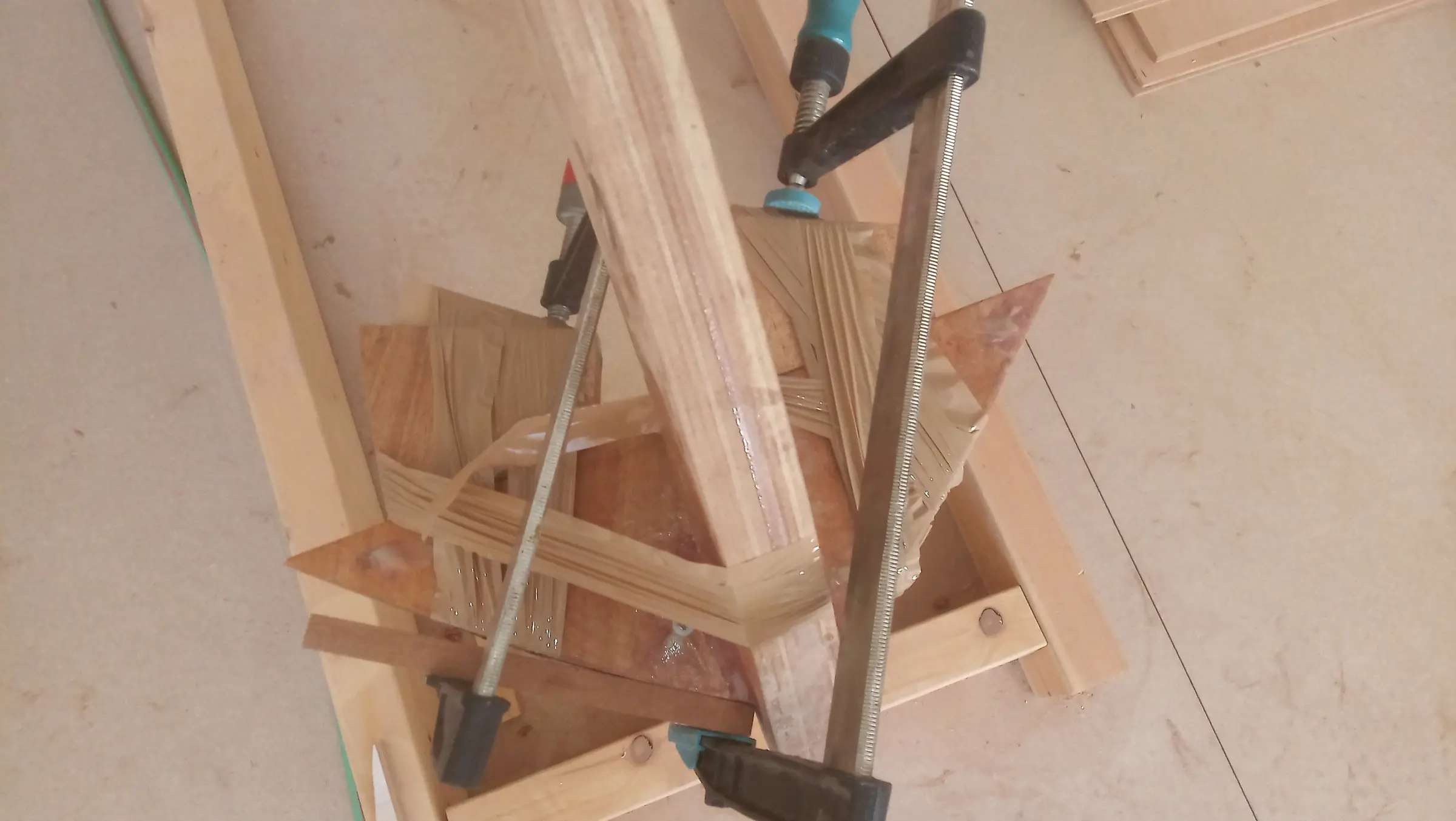
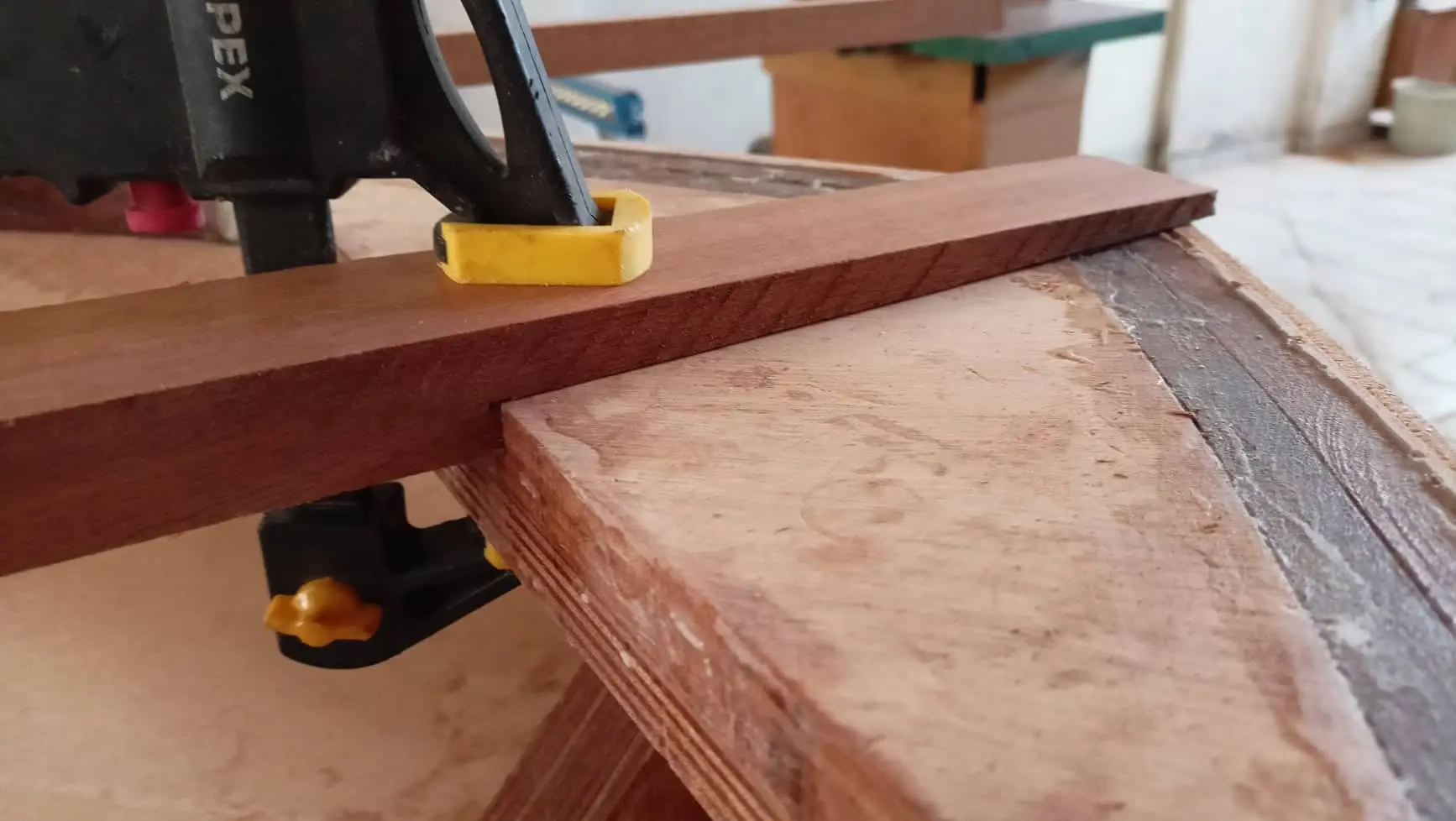
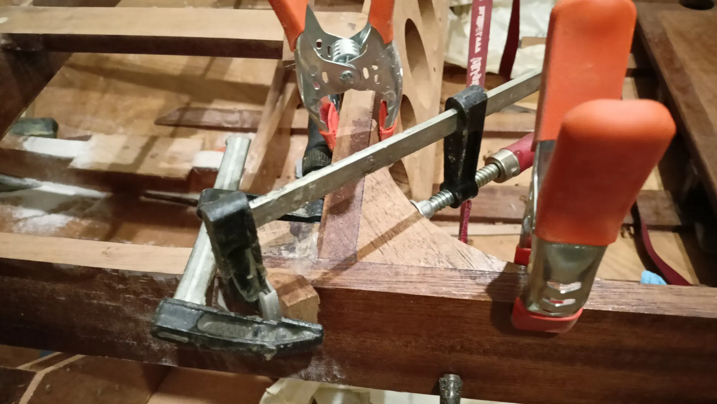
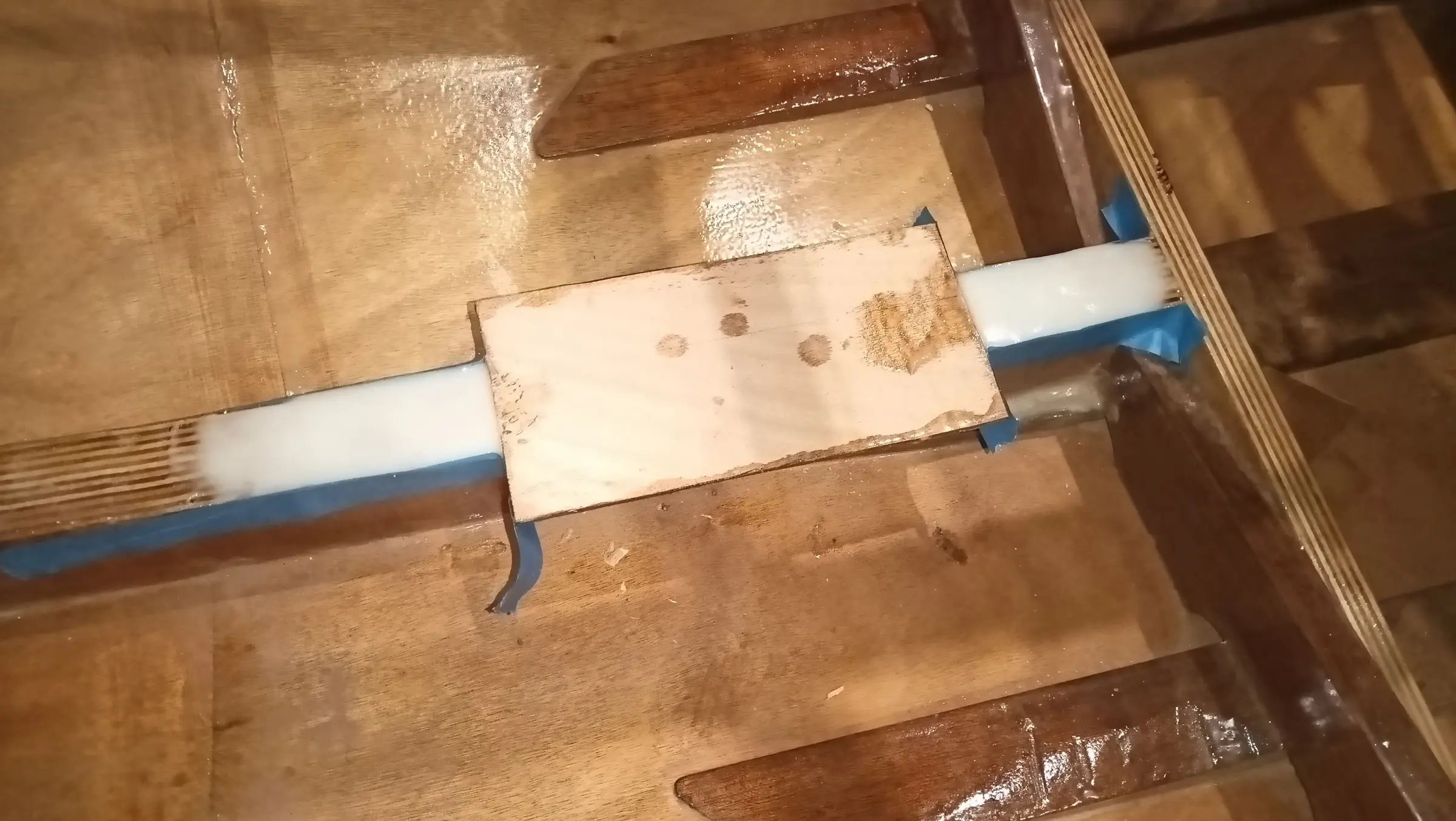
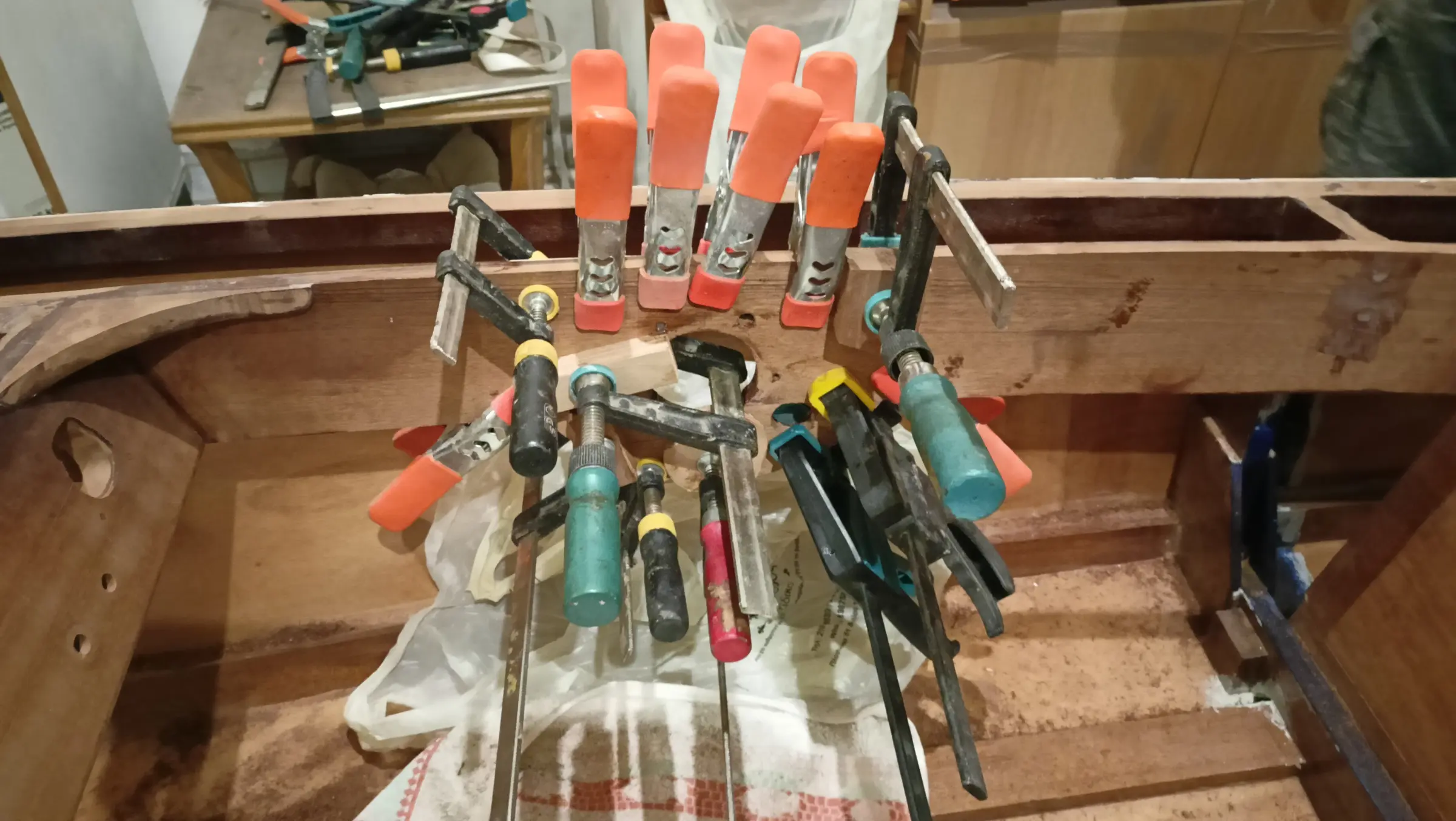
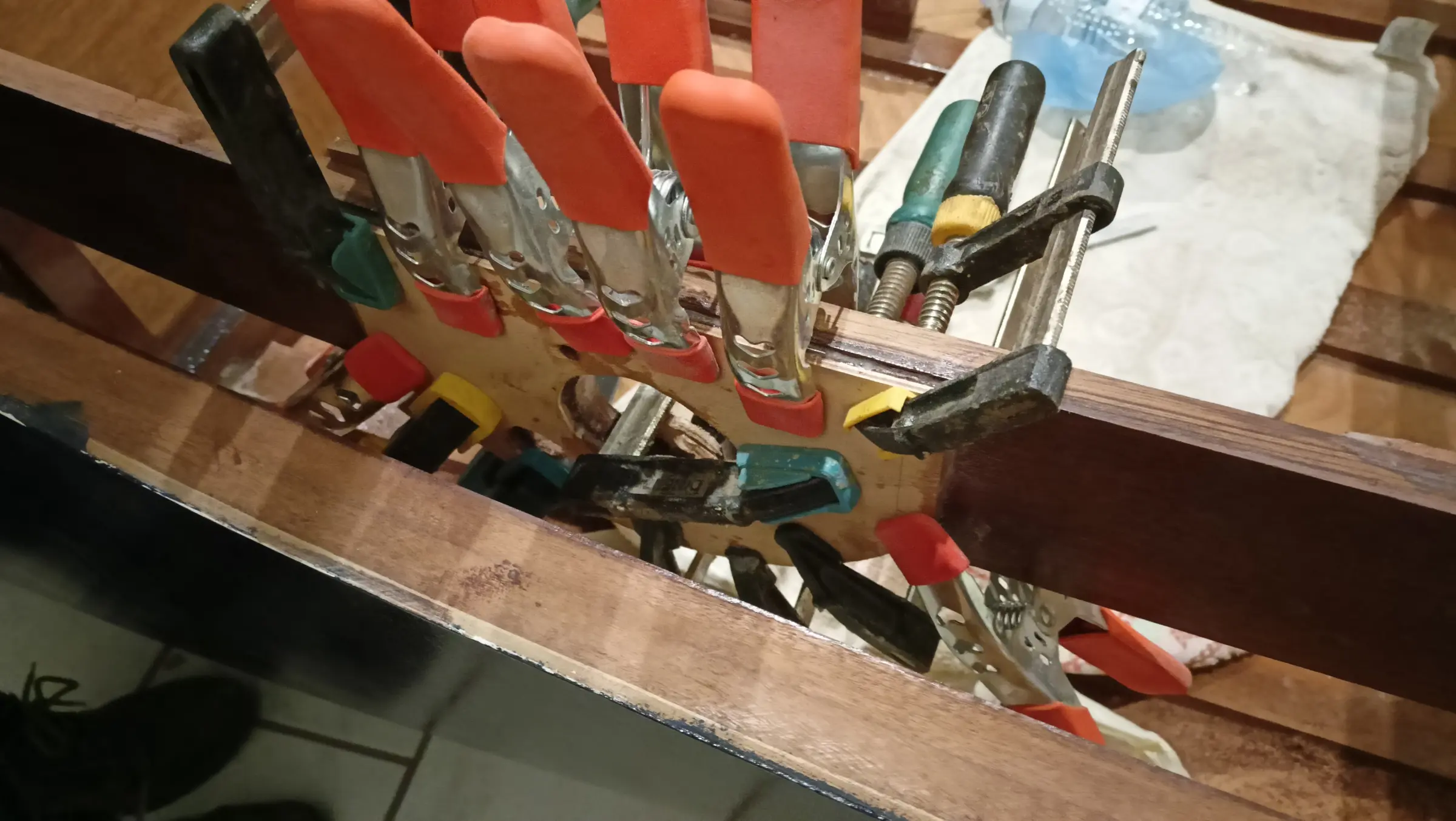
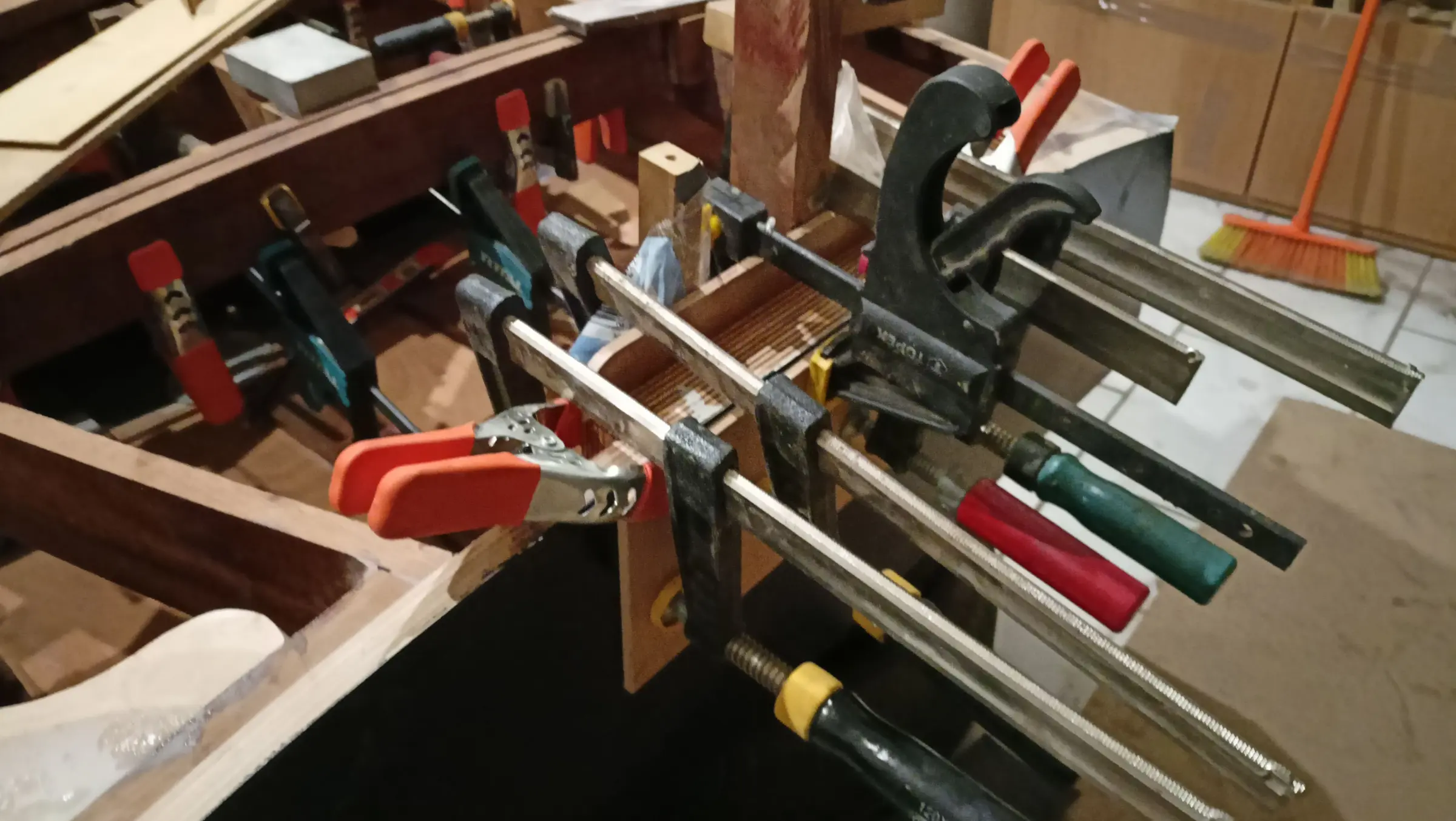
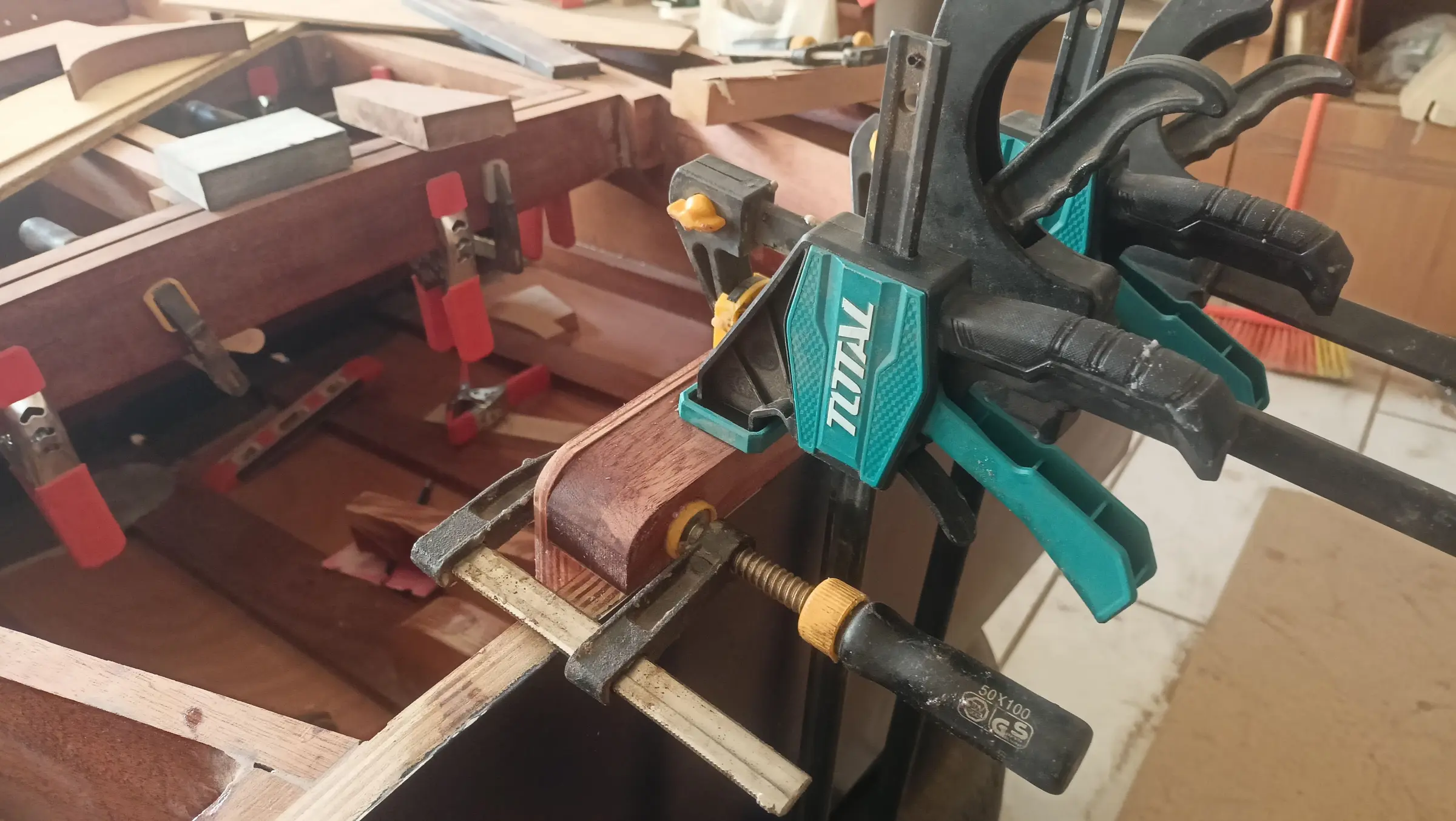
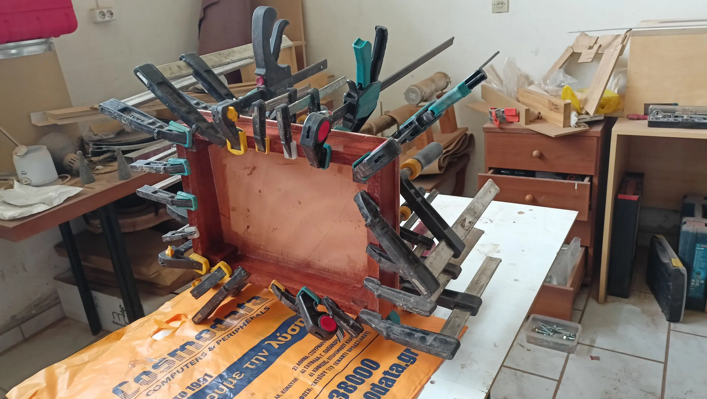
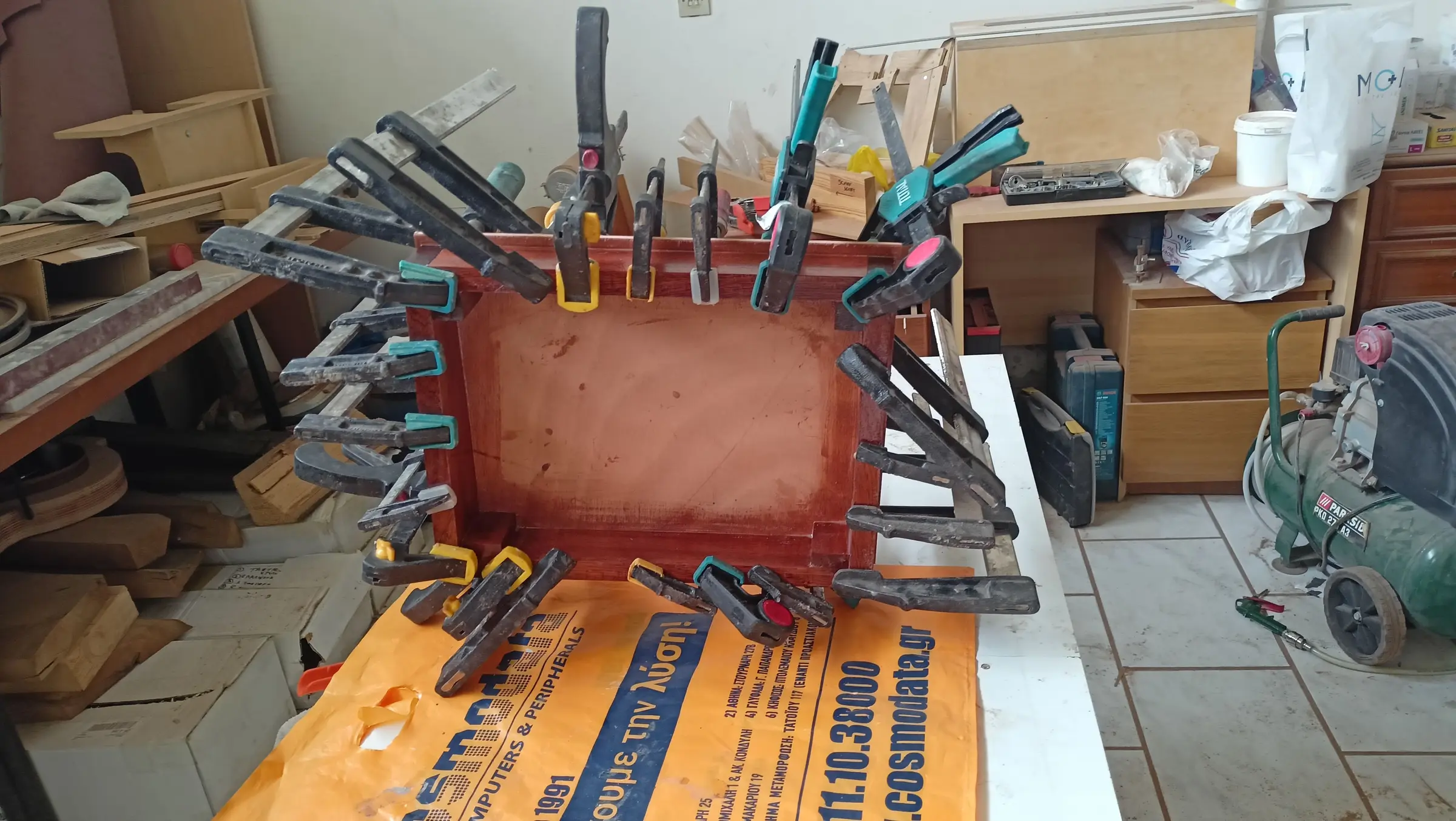
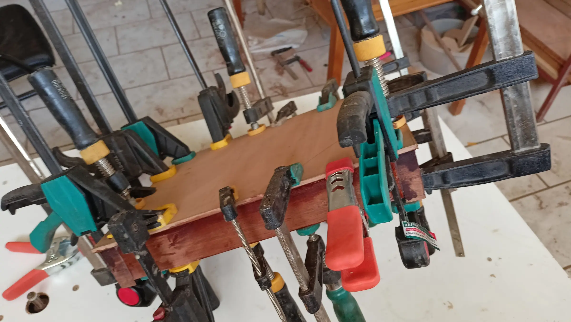
The next job was gluing the motor reinforcement to the transom, and the transom to the keel. Because the clamping had to reach a long way, and because I do not own clamps with that much capacity, I used rubber cut from bicycle inner tubes, quartered lengthways.

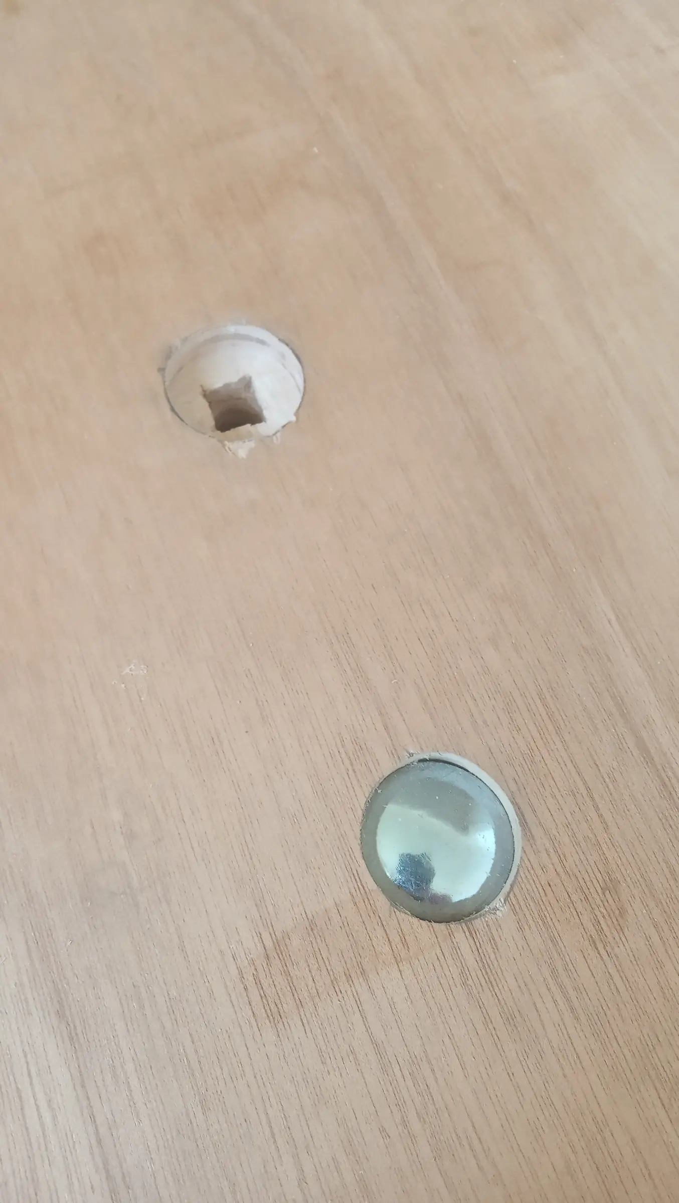
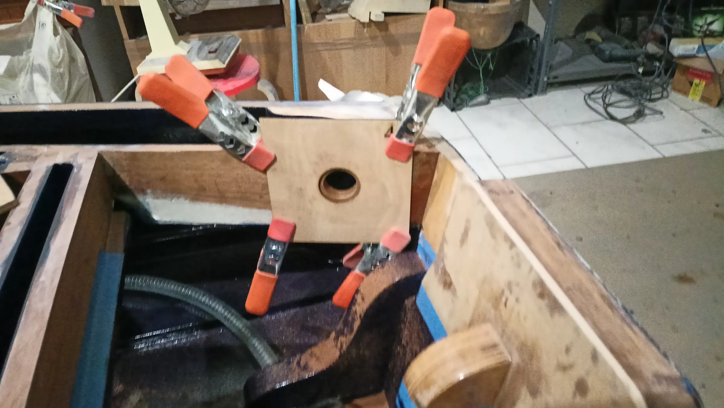
The holes for the carriage bolts in the transom were drilled along with the recesses for their heads. Once they were bolted up, the gap was filled with resin.

The same was done with the bolts that went through the transom and the motor reinforcement.


34 h

Building the strongback, and setting up the frames, transom and keel

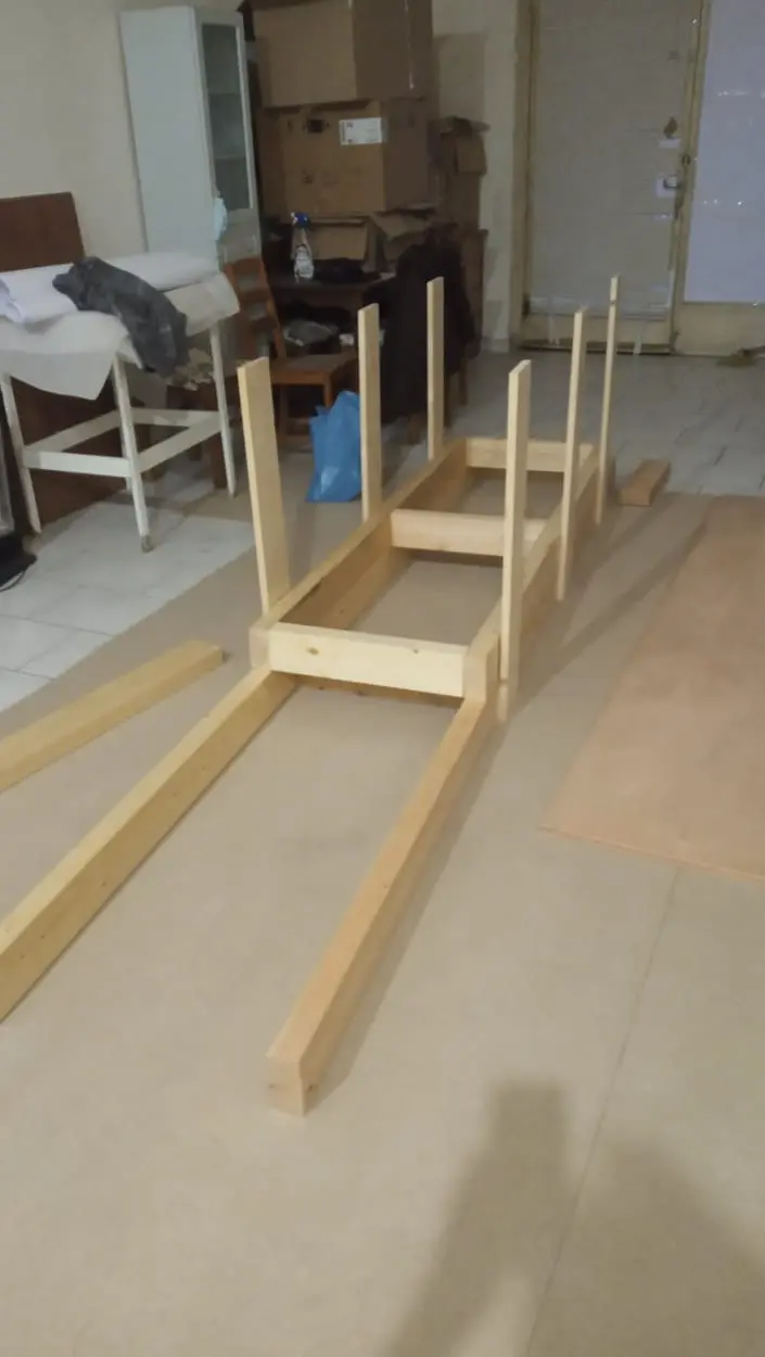
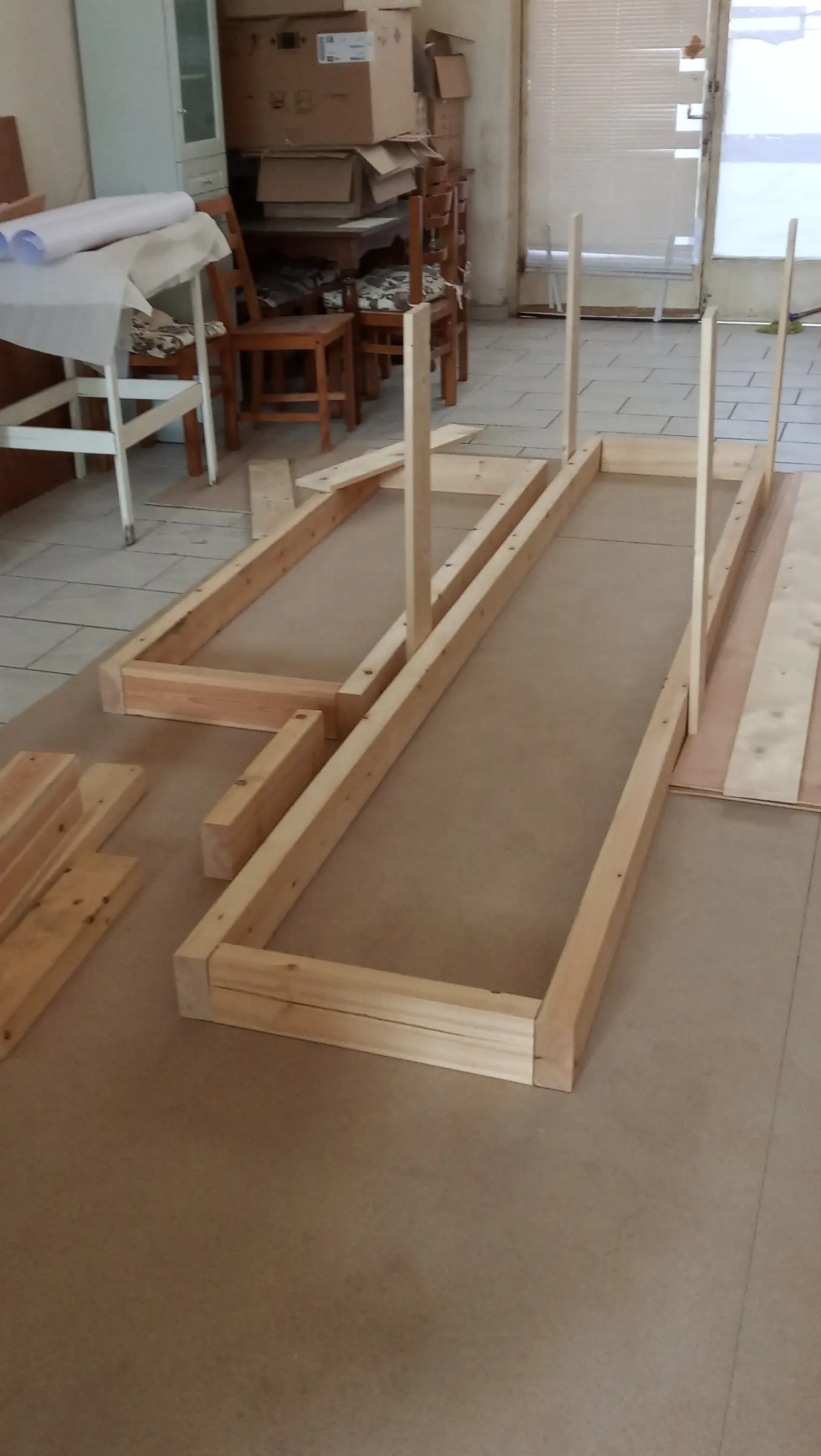
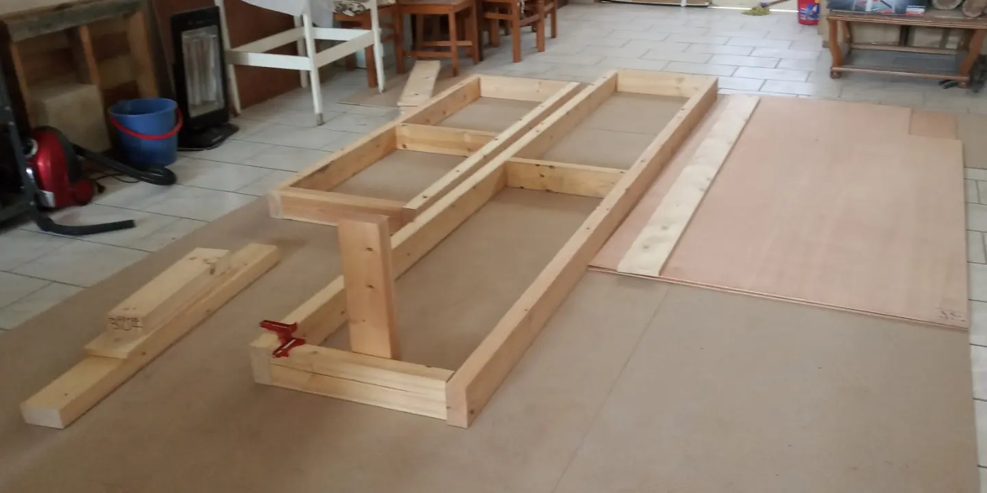
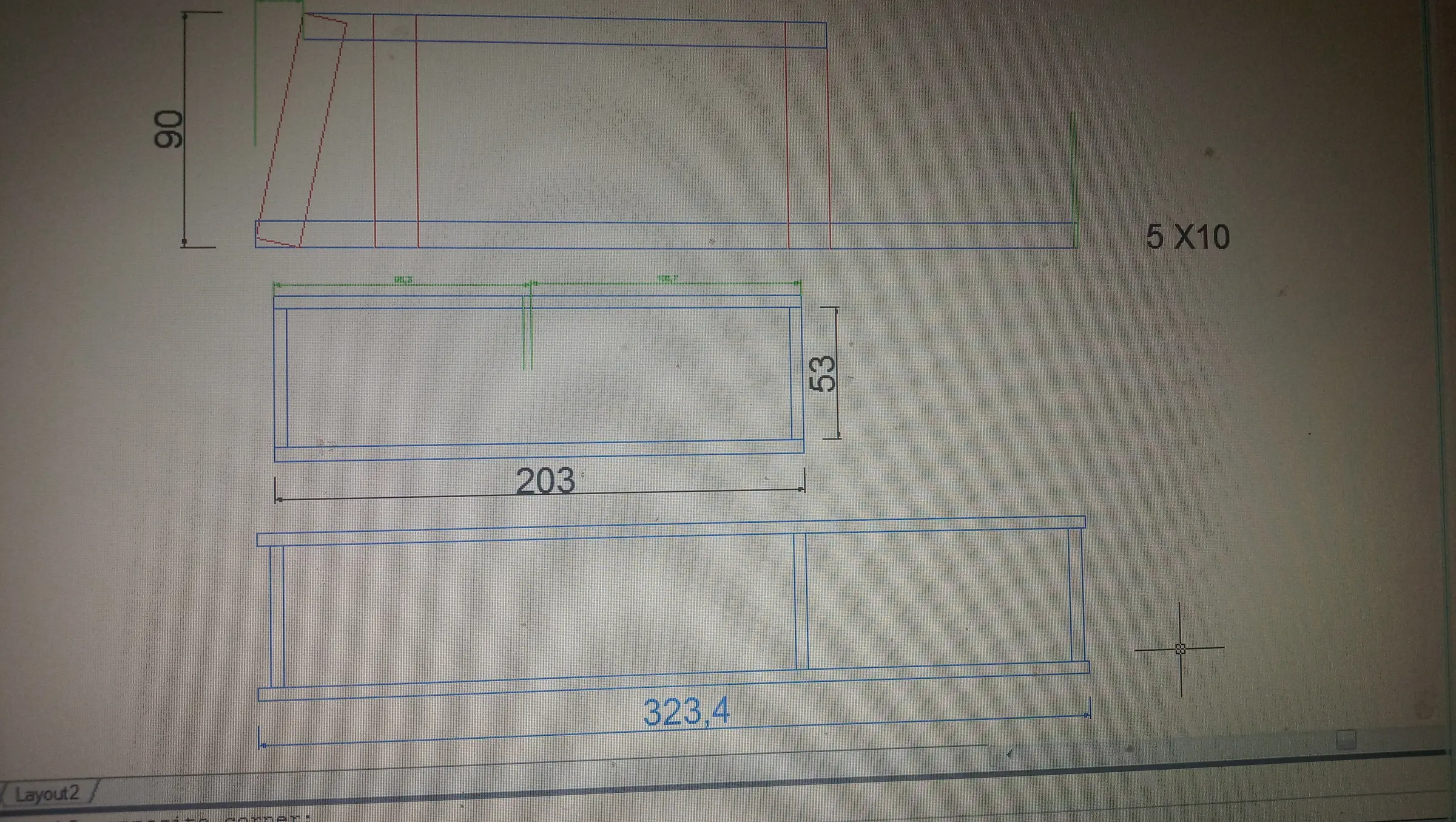
The first building base is made so that the boat's framework can be built on top of it, up to the point where the hull is finished. Once that work is done a new base will be built and the boat will be turned right side up so the interior work can start. It was built out of Swedish pine. It cost around 120 euros including the screws. Below are some photographs of building it and the drawings. Some changes were made along the way because I found it was not entirely practical. It took about 5 hours to build.

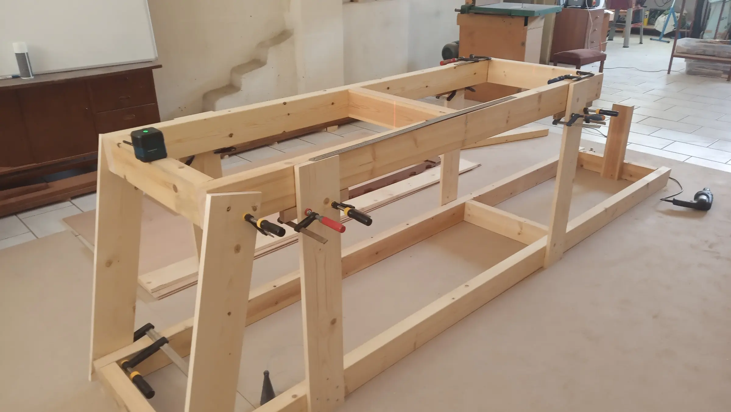
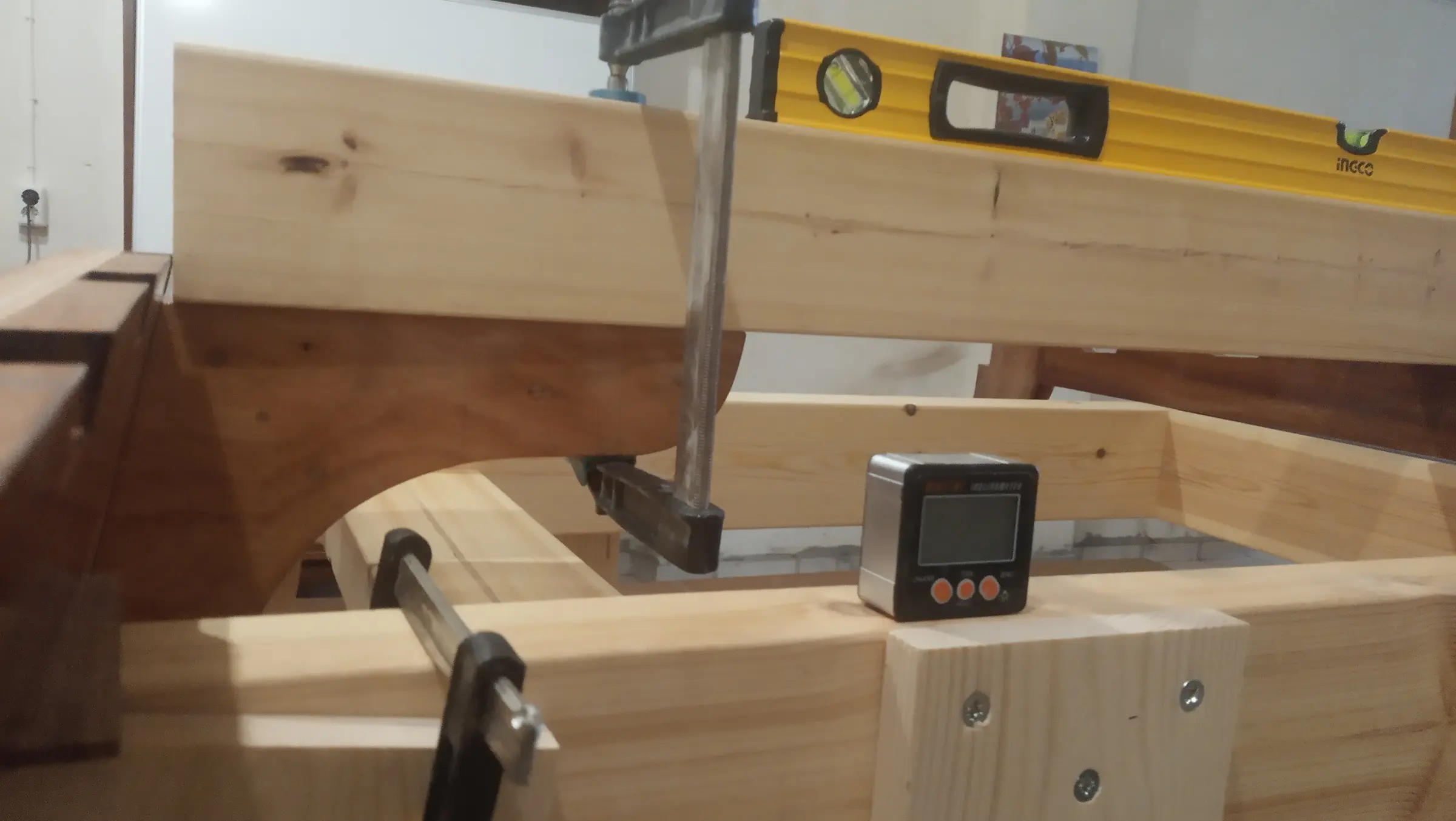
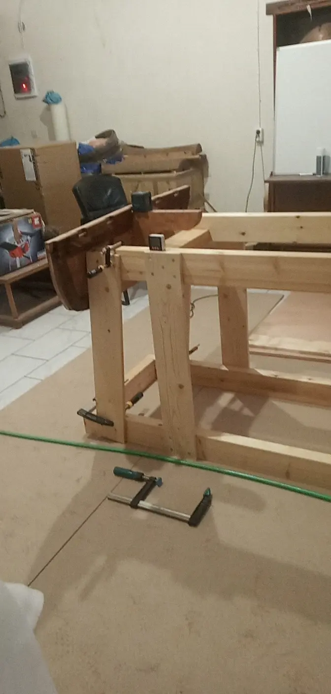
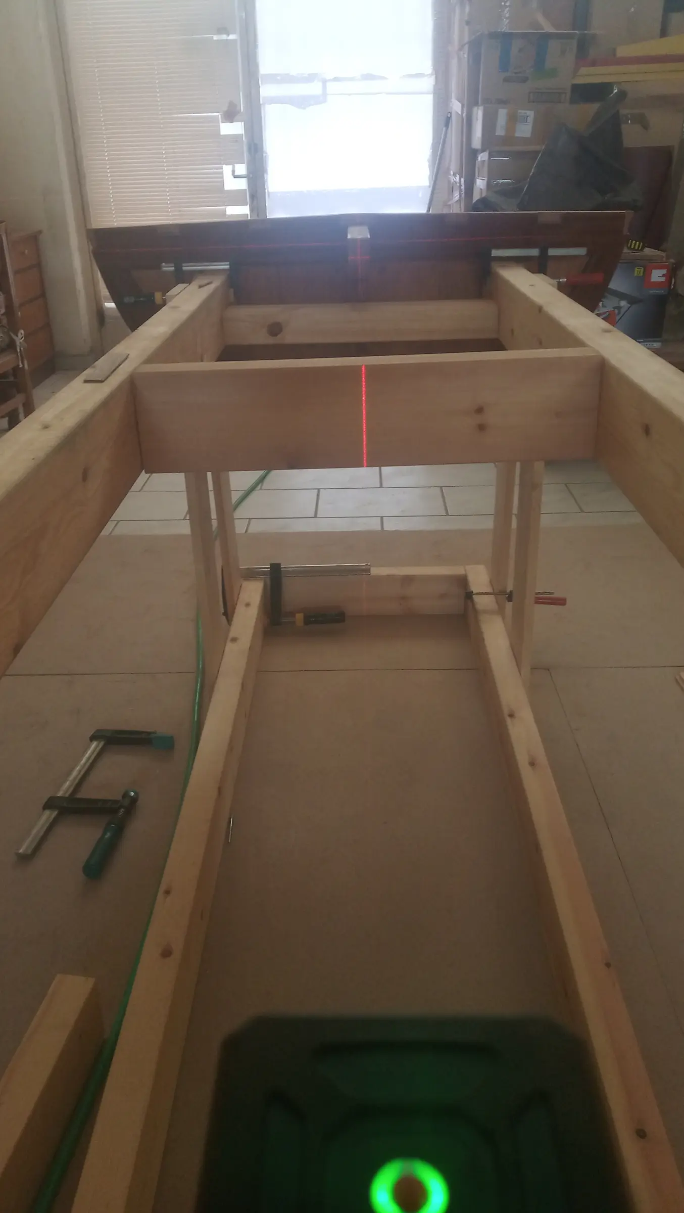
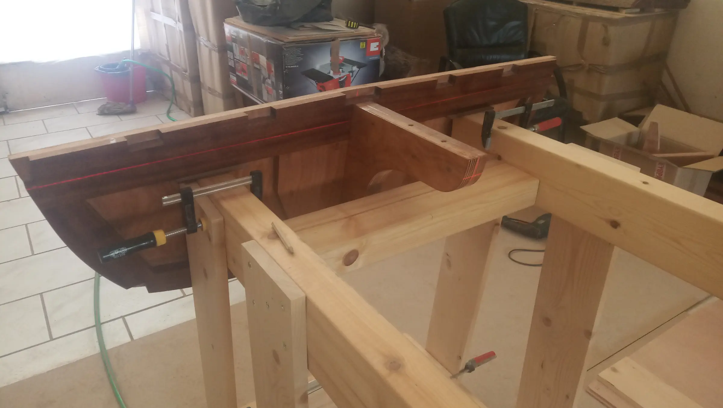
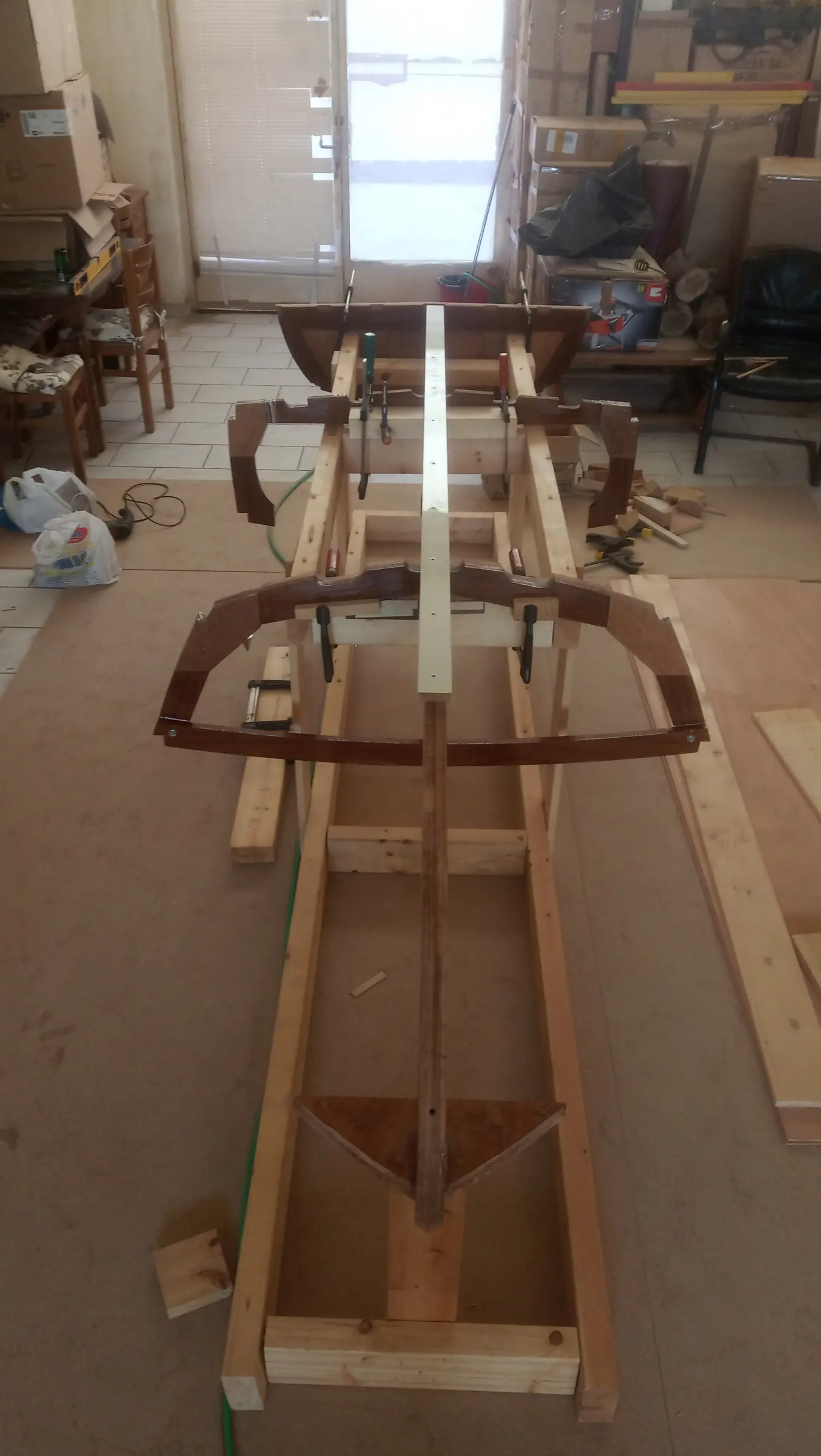
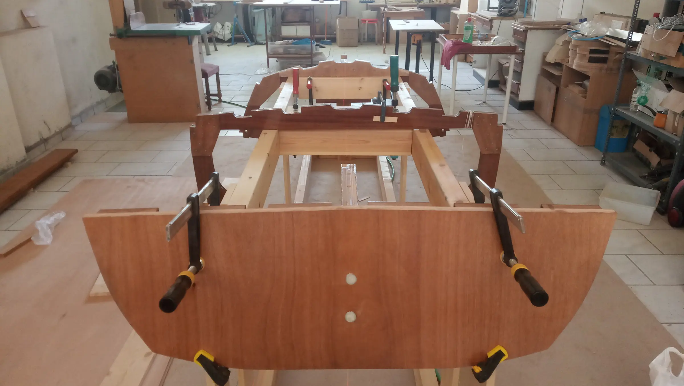
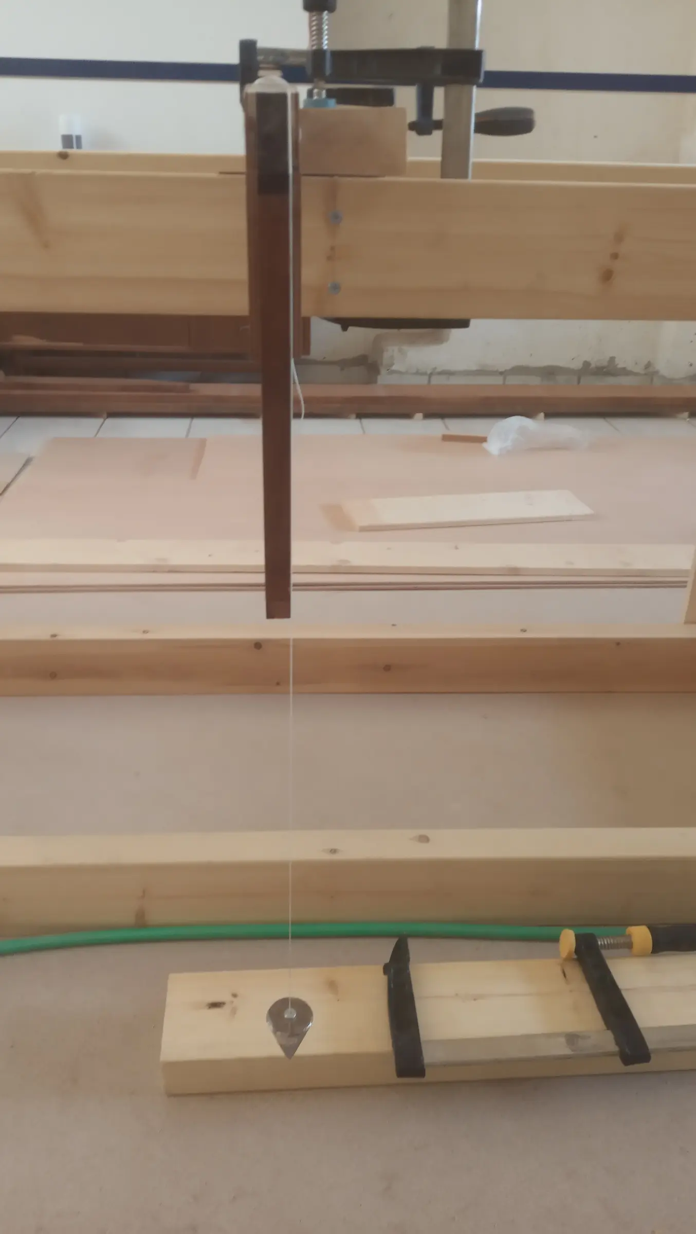
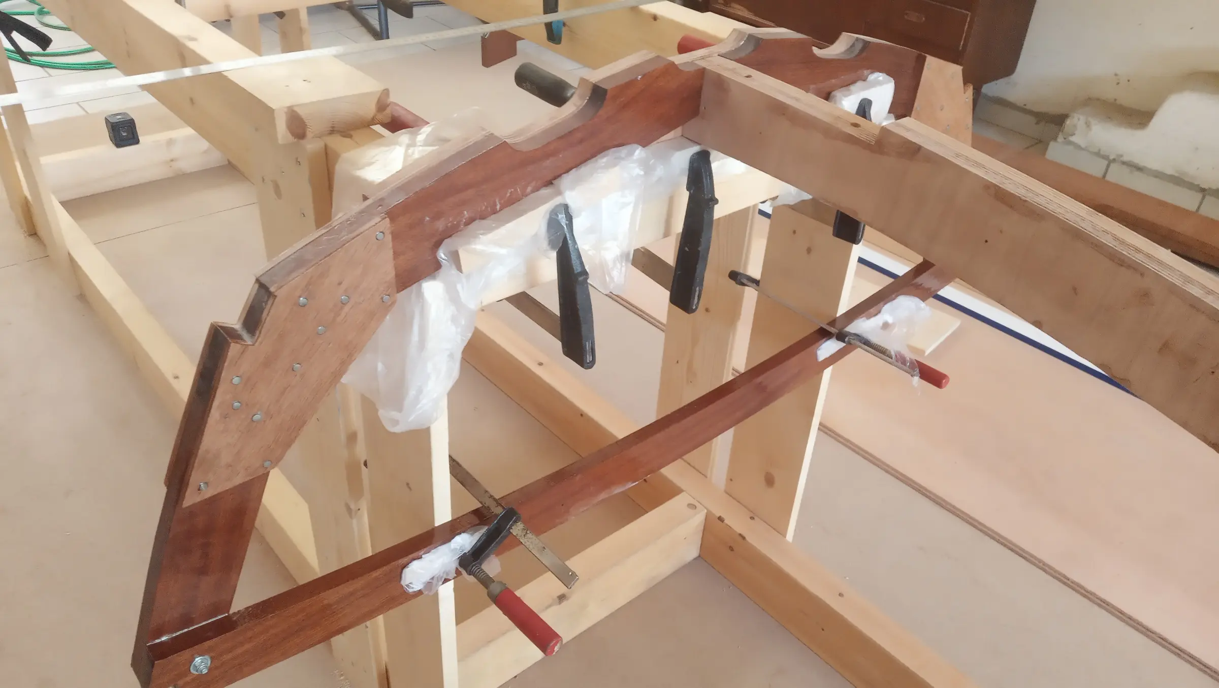
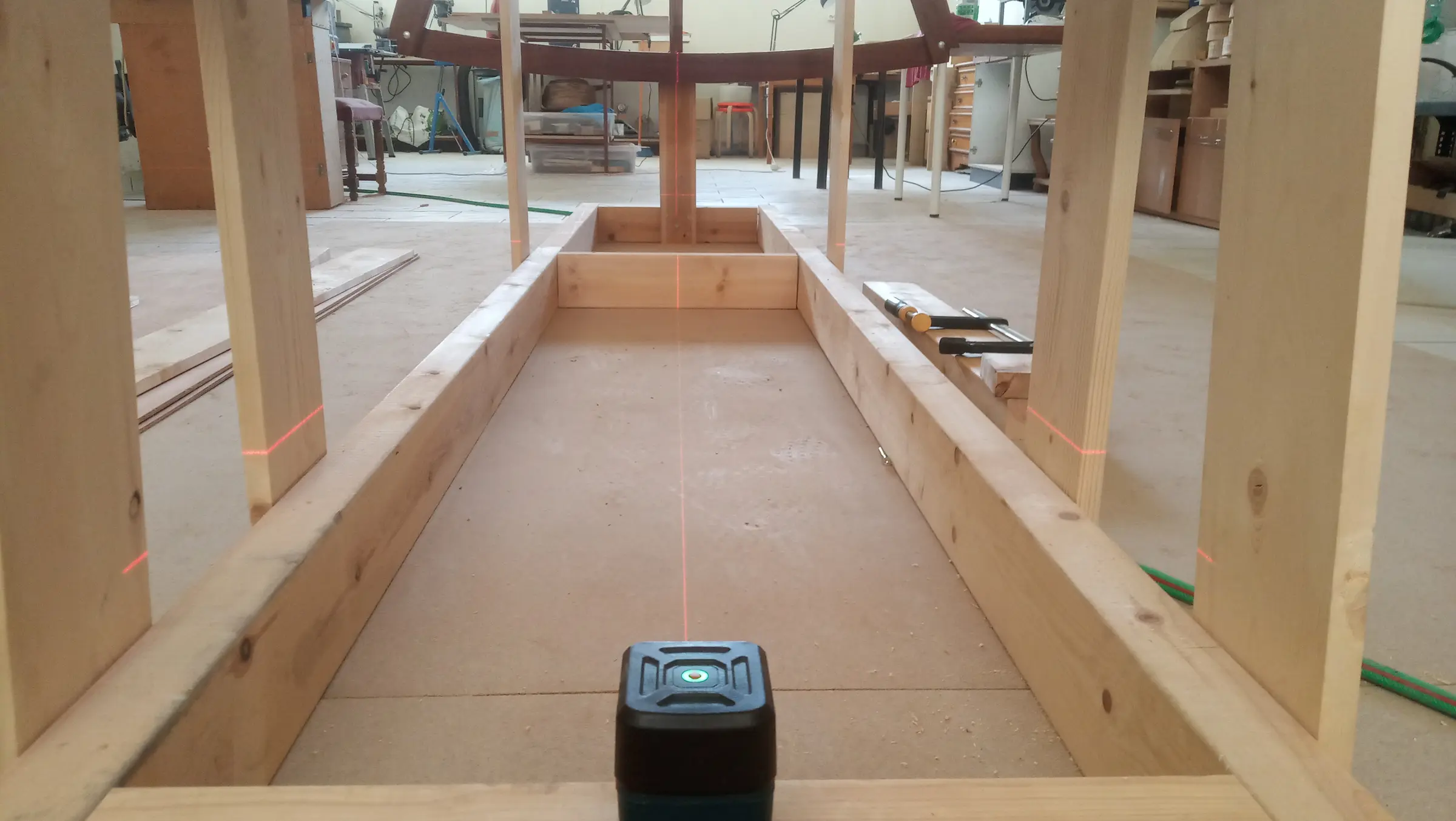
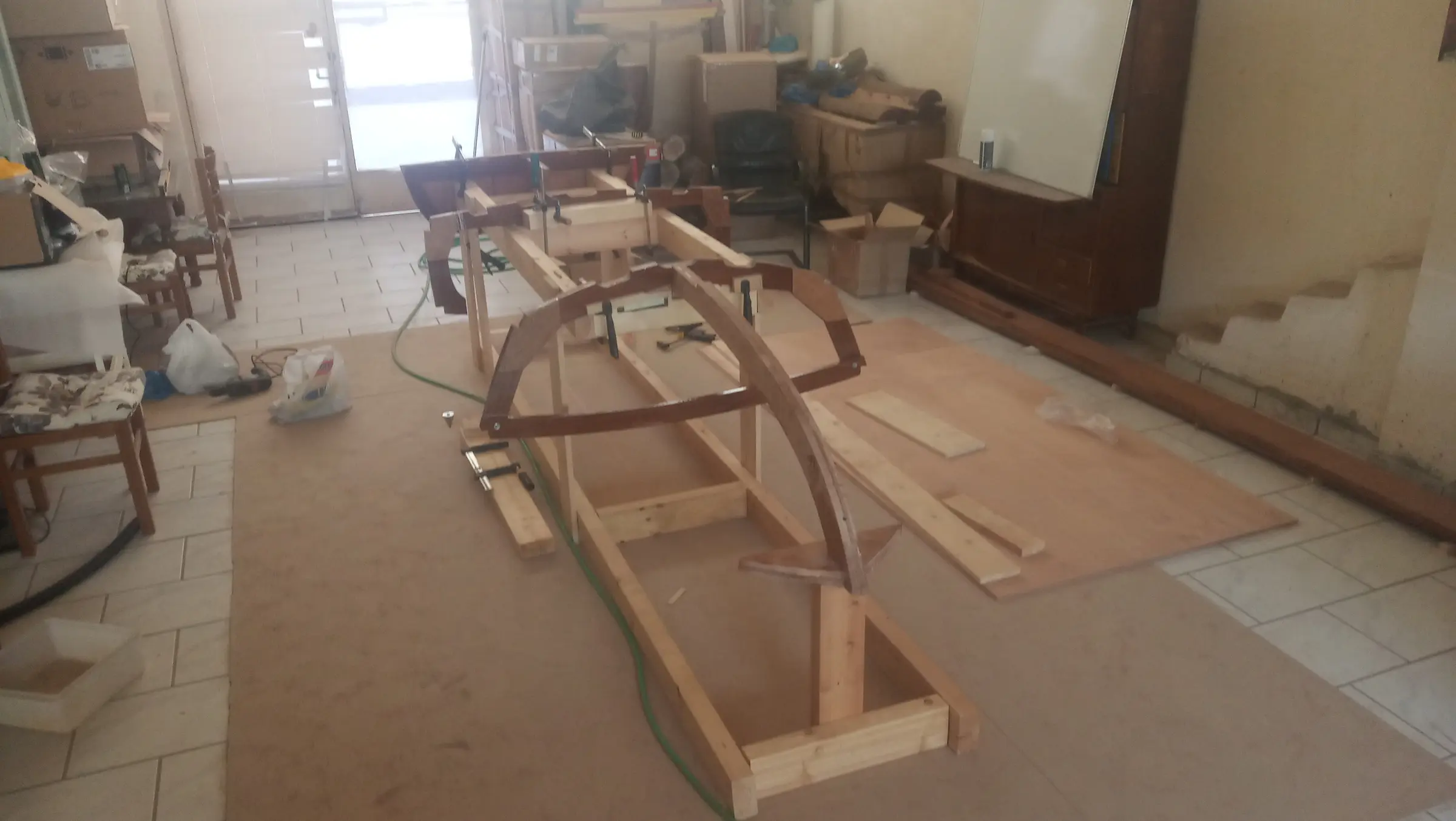
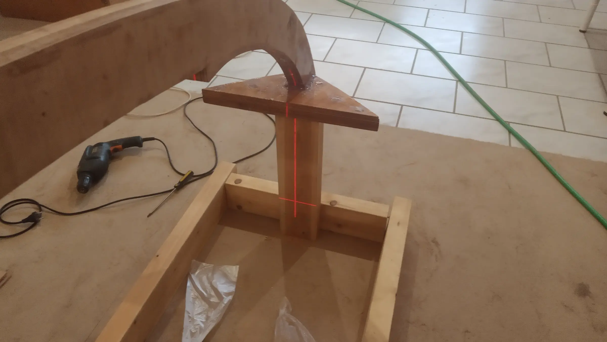
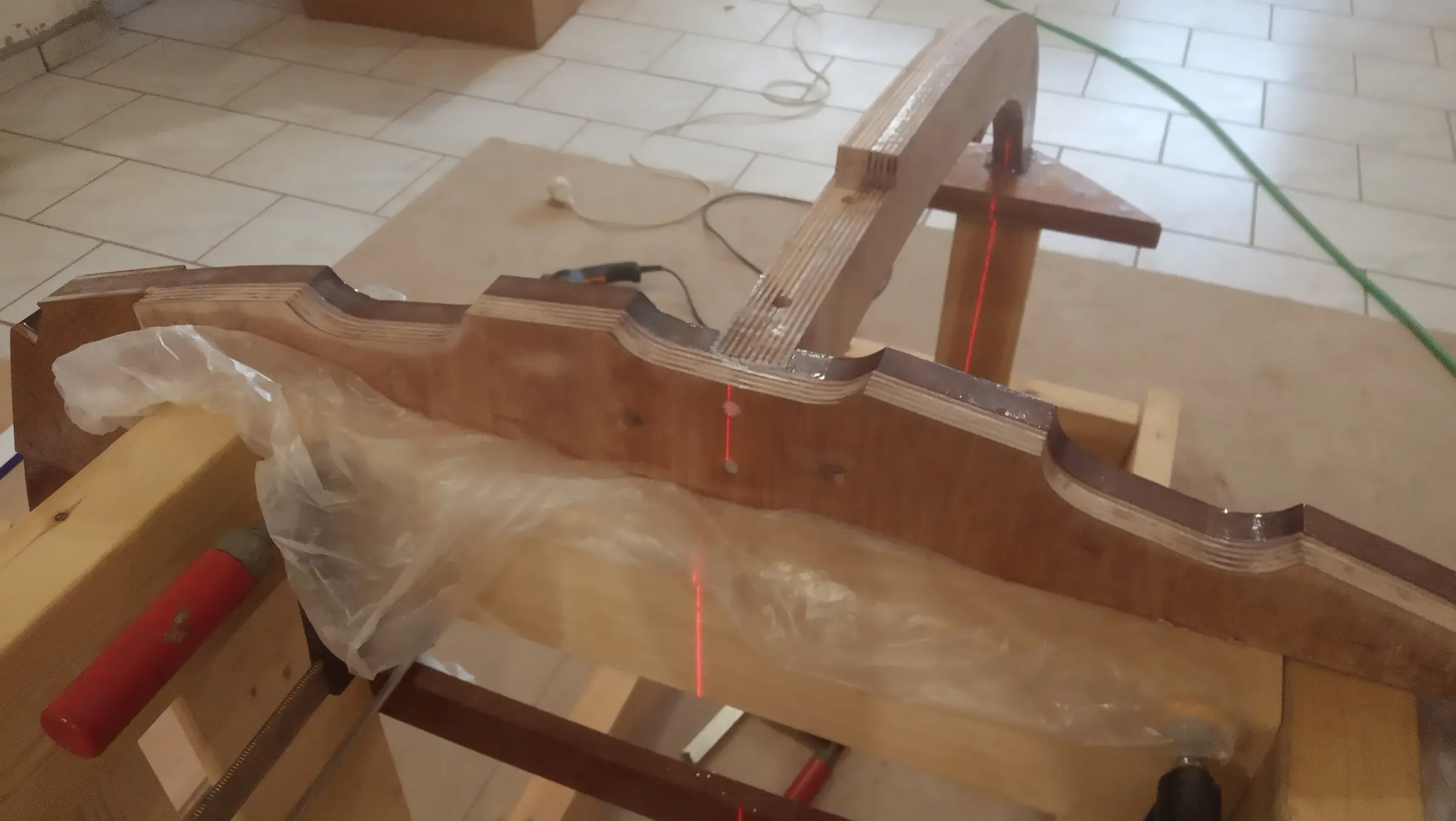
Next the frames and the transom were set up on it, and the hardest job so far began: levelling and aligning them. Unfortunately the Swedish timber was poor quality and warped, so everything needed packing out with blocks, wedges and so on. That, combined with the transom having to sit at 12 degrees to the keel, meant the job took 4 hours, and another 4 afterwards because I found I had made a mistake the first time and pulled the whole lot apart. A laser bought from China was invaluable for this. A few photographs...

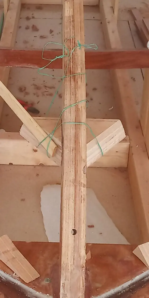
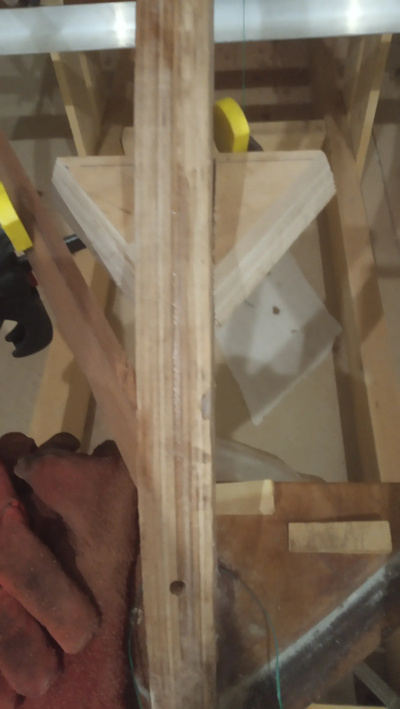
With that done it was time to glue the forward section of the keel onto the frame. The joint was backed up with two screws. A few photographs...

The next job was cutting and gluing the keel and the rest of the timber along the bottom of the boat.

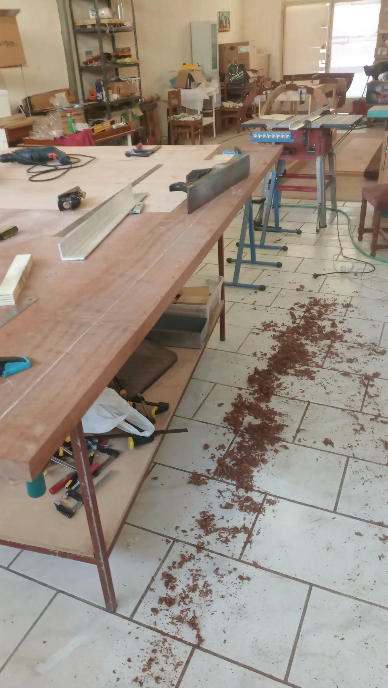
The keel was cut and then dressed with a hand plane, because my thicknesser is completely unsuitable for stock that long.

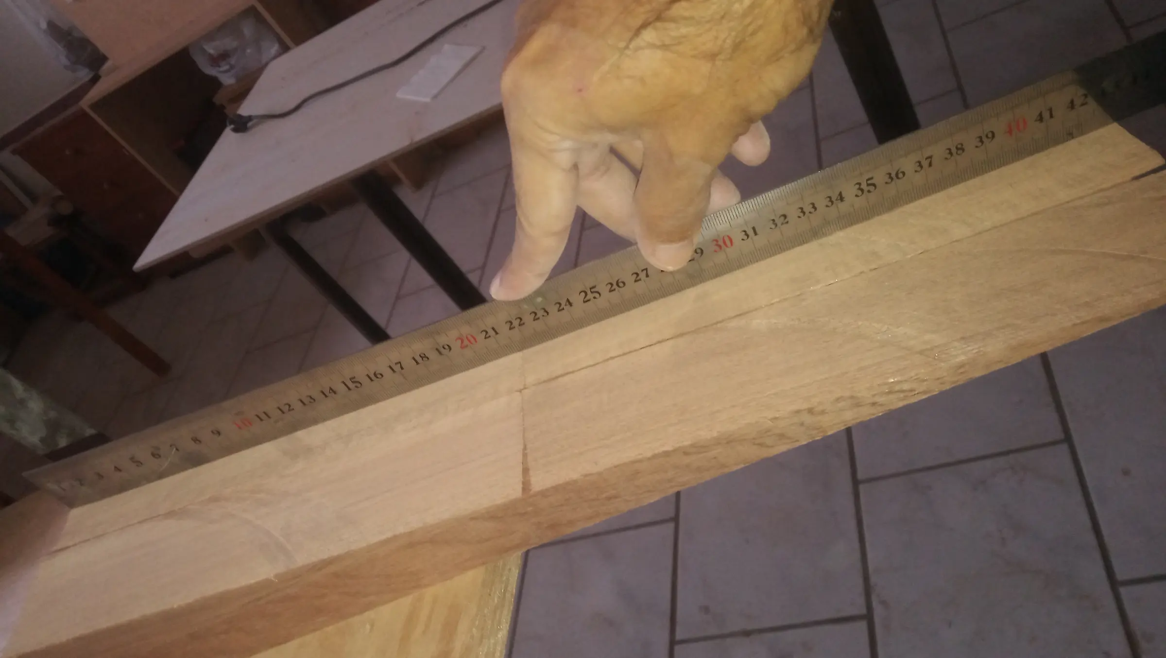
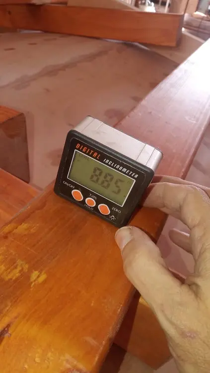
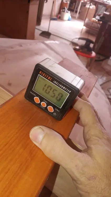
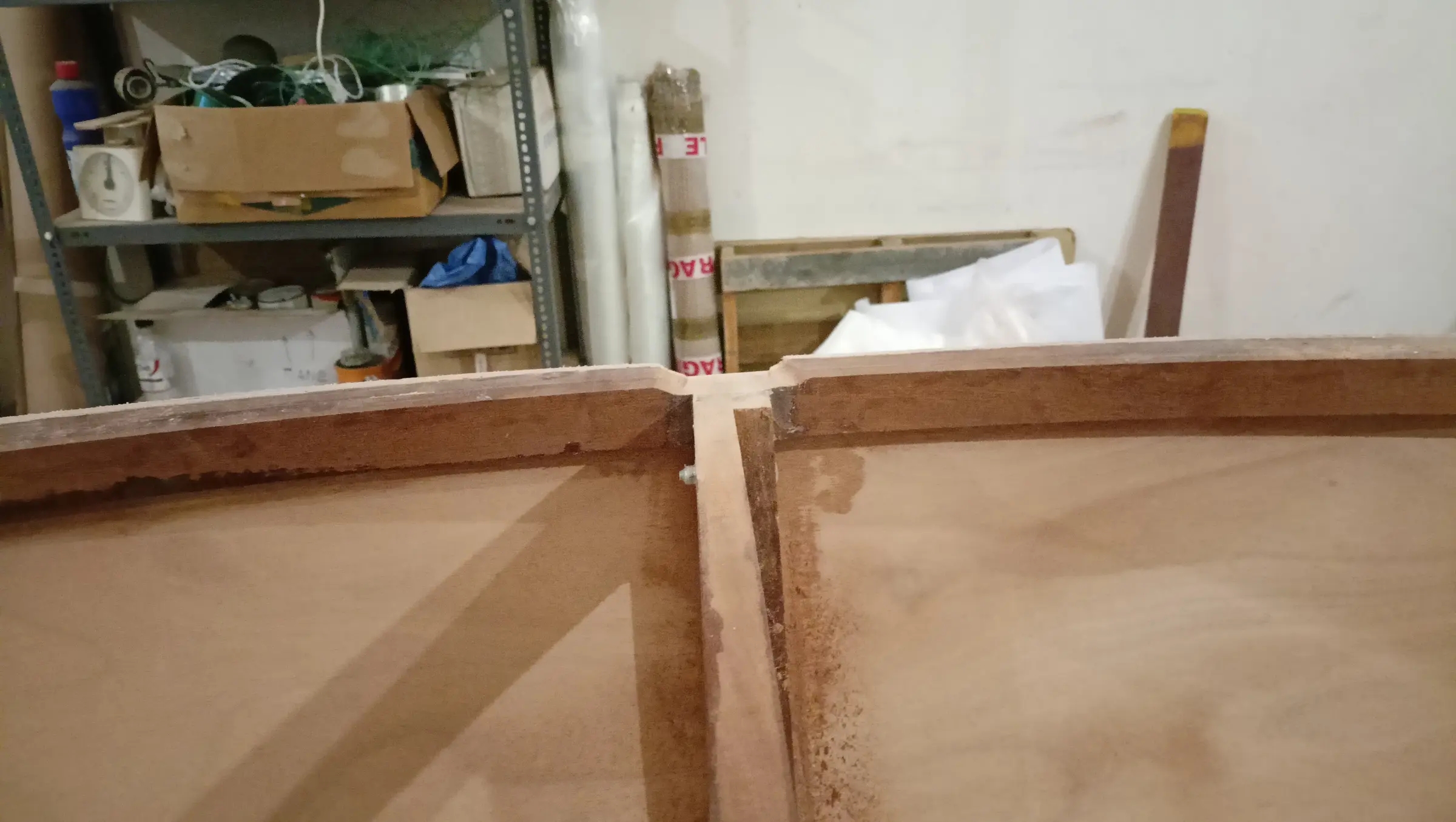
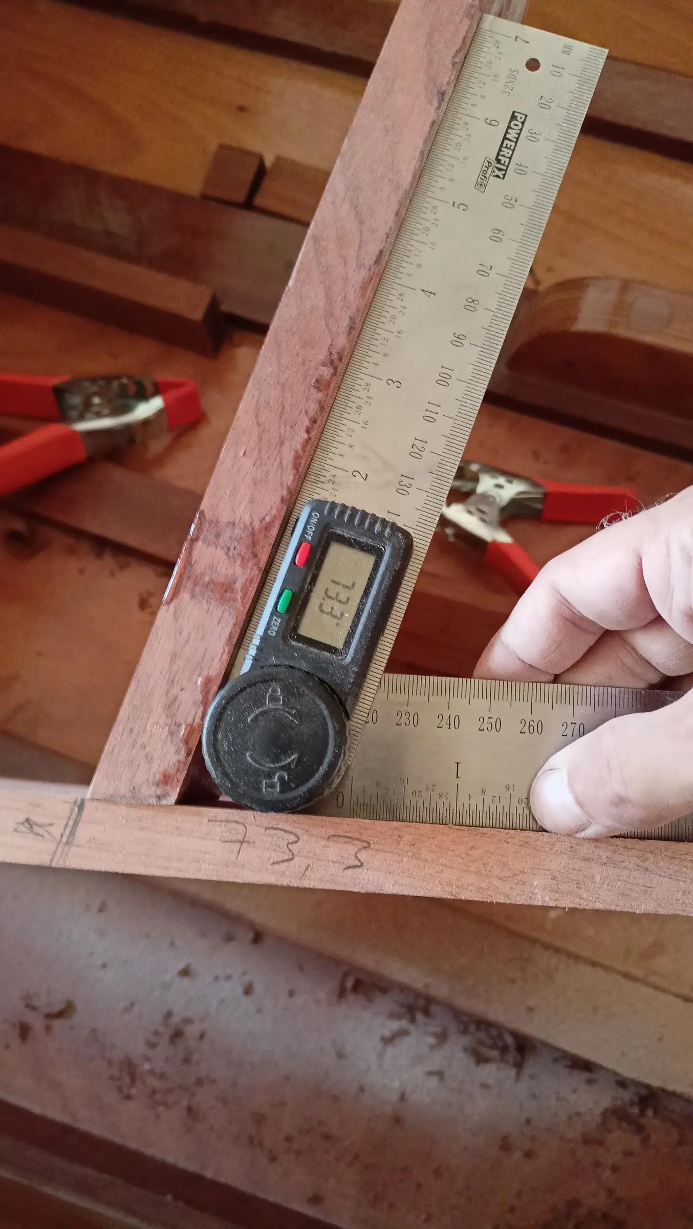
I found that the plans have an error. Where the two pieces of the keel meet they are not parallel, there is a small angle of 2 to 3 degrees. To get them to glue up properly, a wedge was glued onto one of the pieces.

The rest of the timber was shaped at a wooden boatyard.

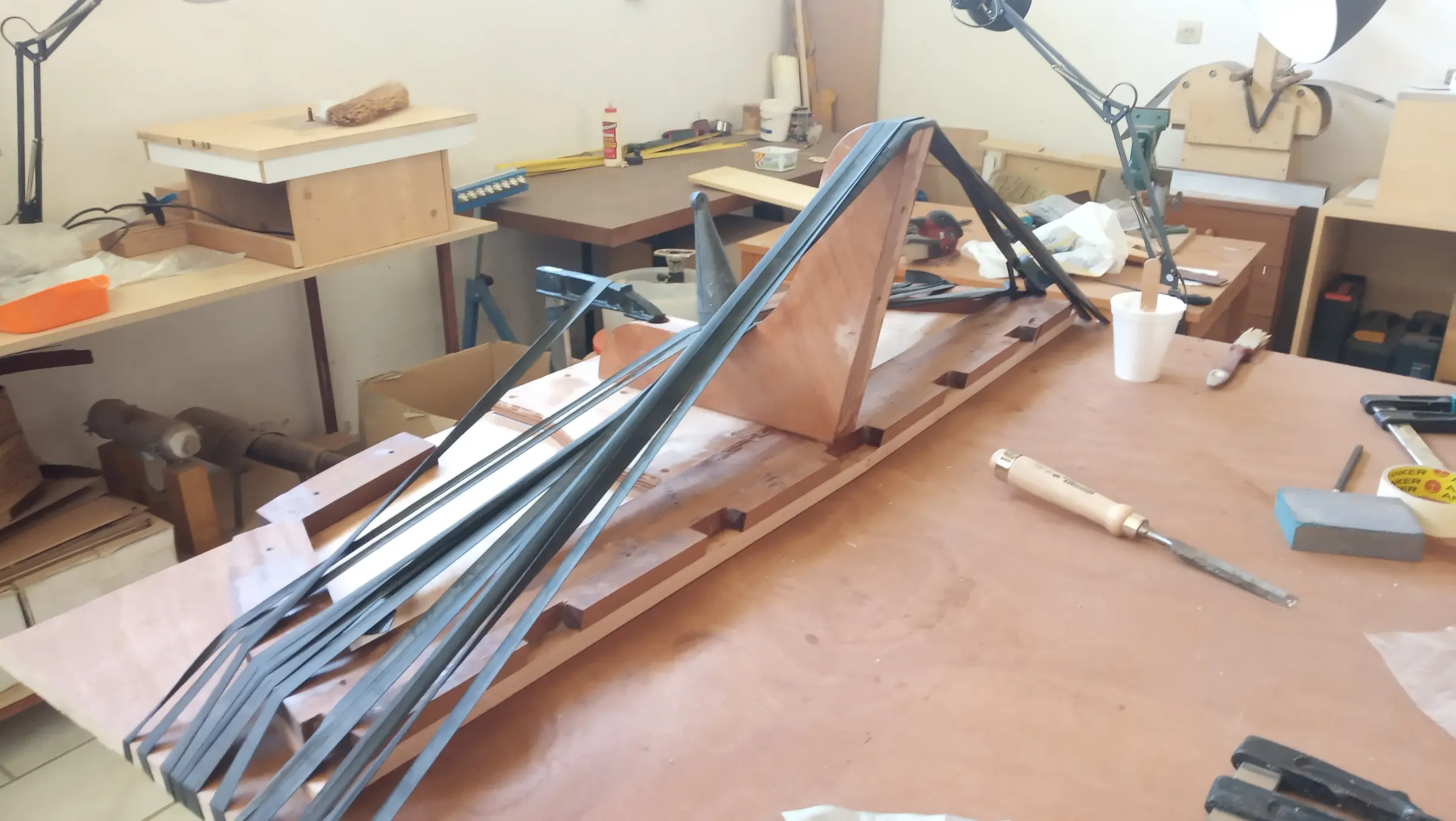
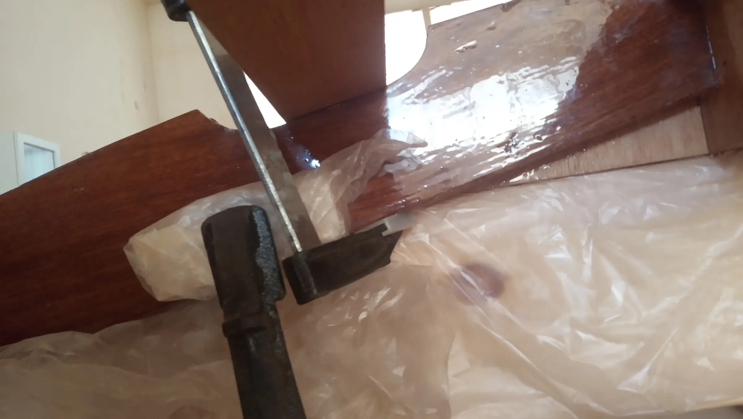
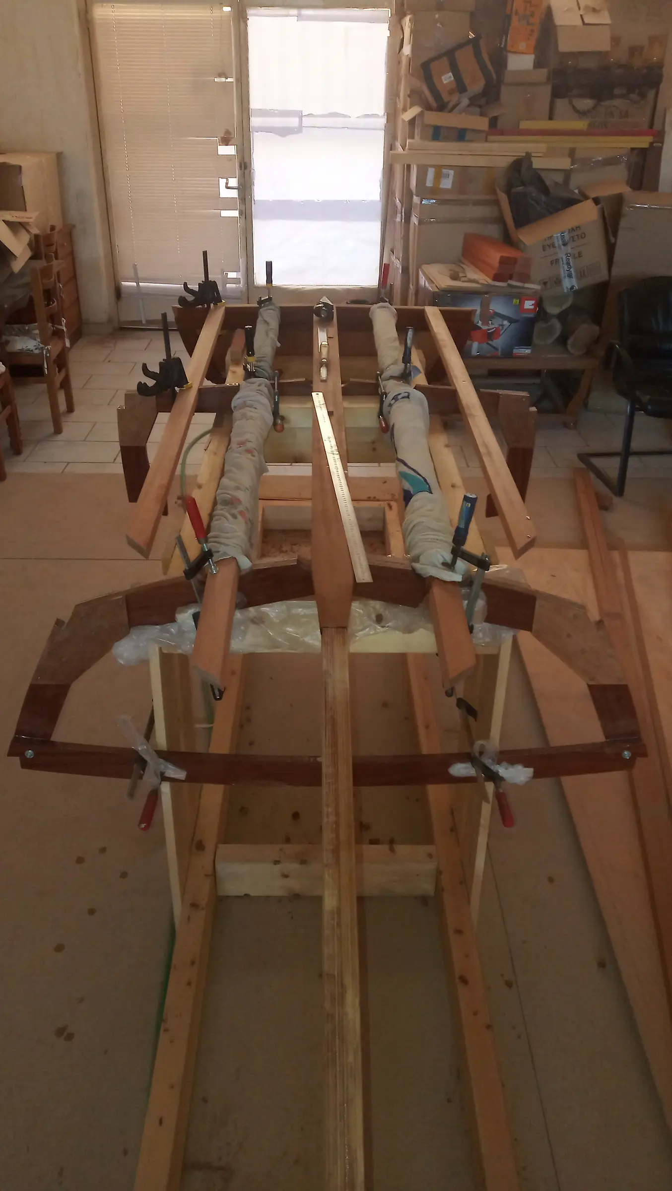
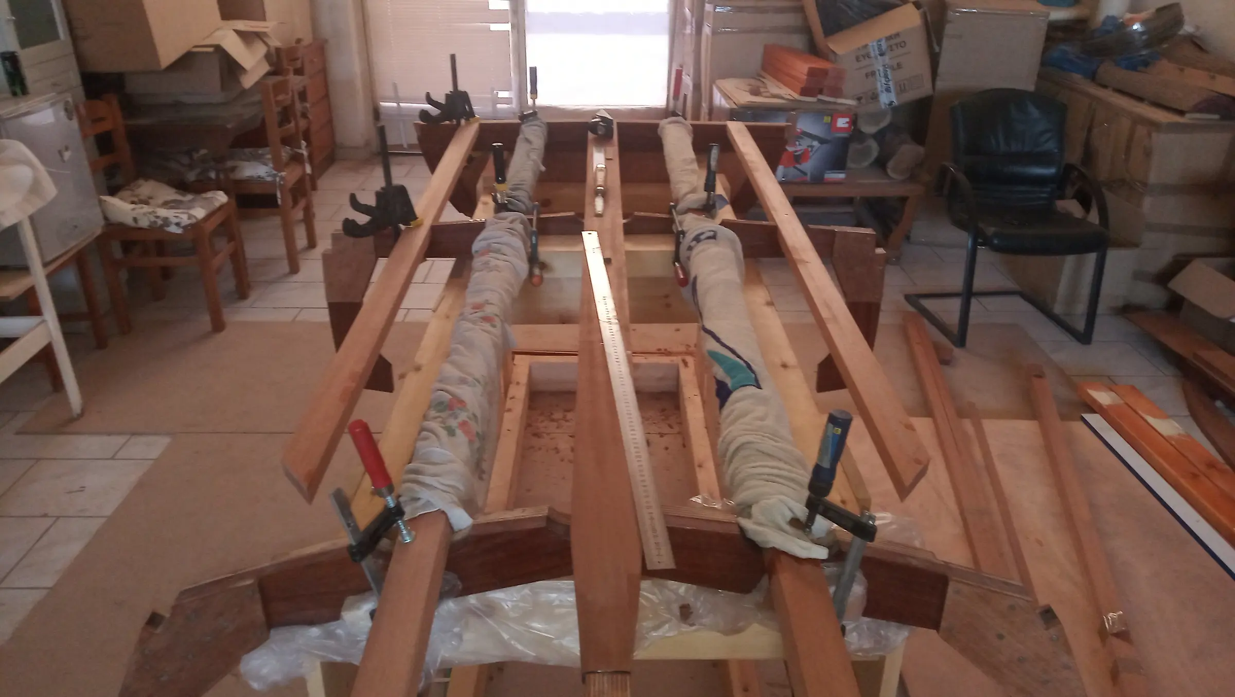
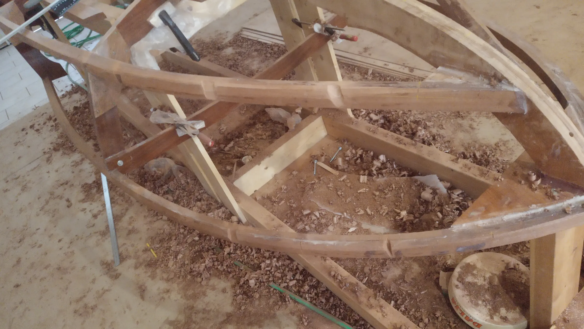
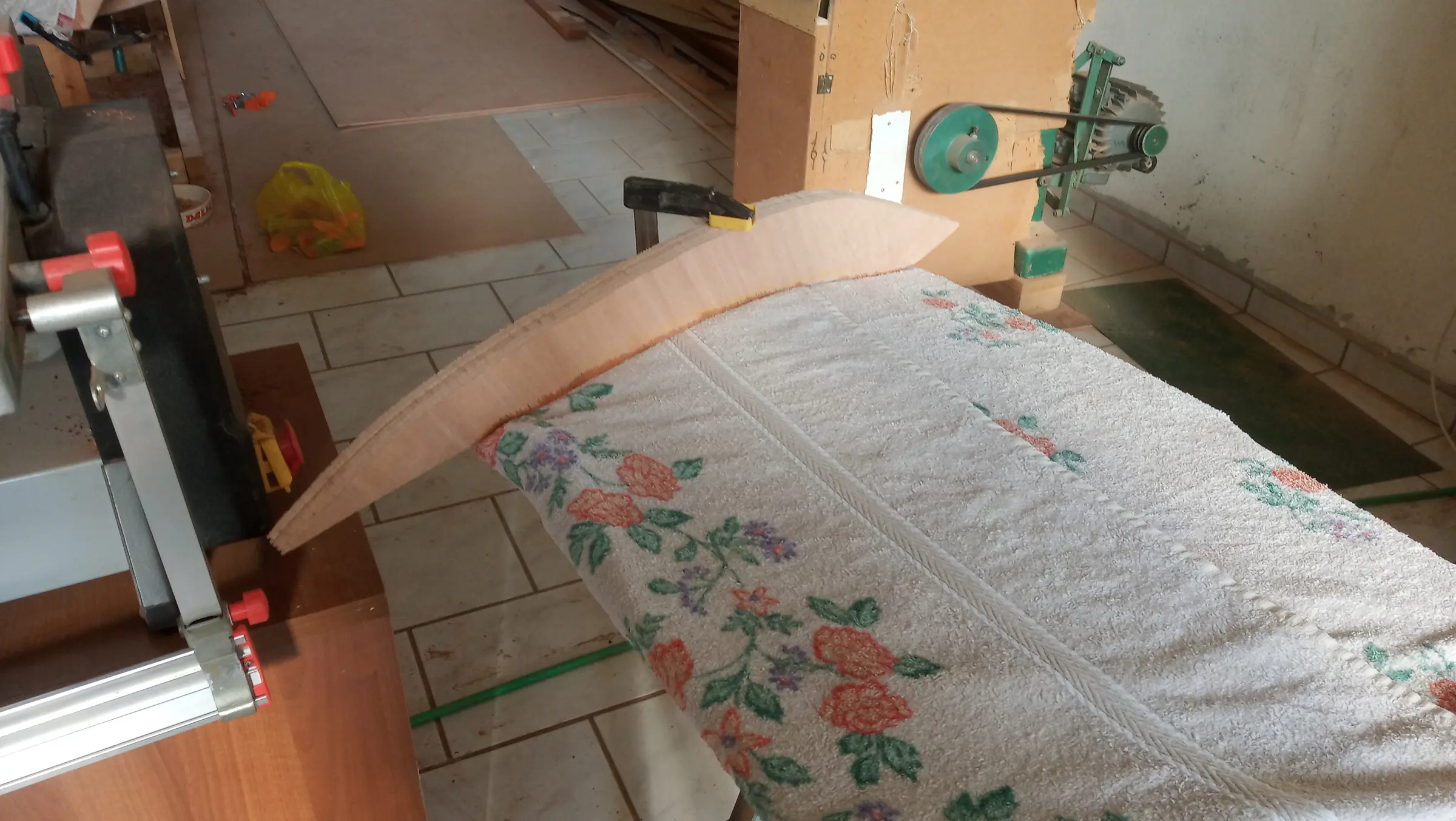
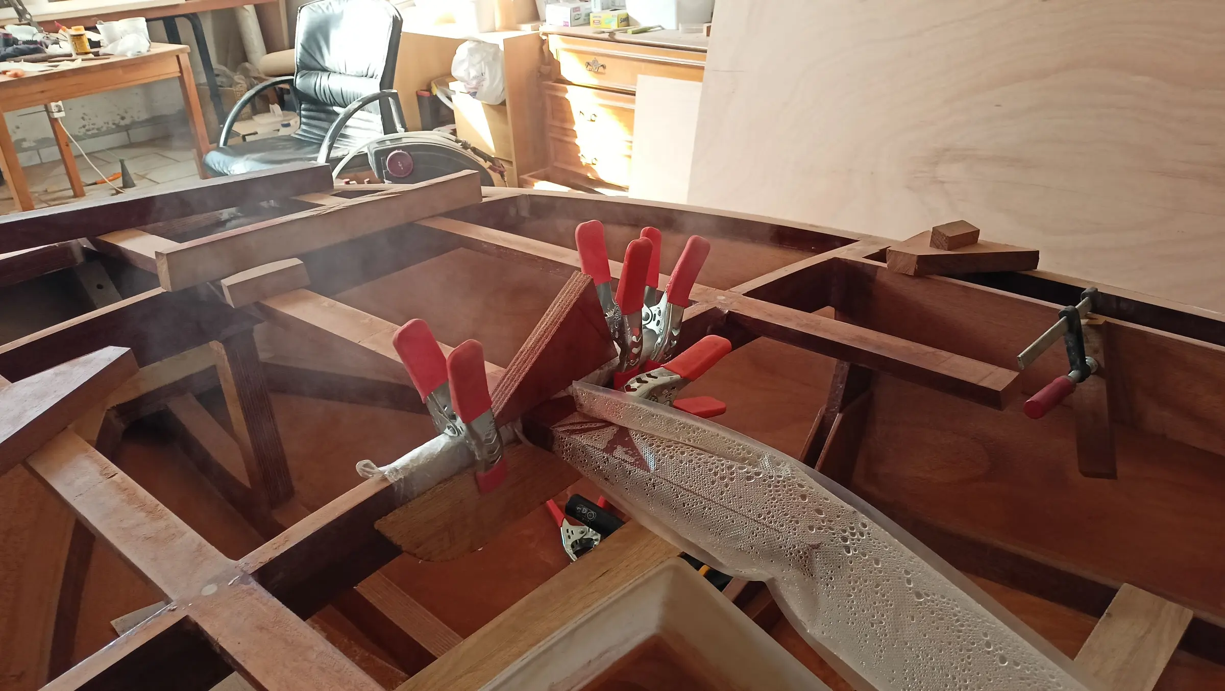
Then, once I had cut the notches in the transom, I offered the pieces up to see how they sat. I found they were not bedding down properly on the frames and would need to be twisted a little along their length. To do that I wetted the timber, wrapped it in wet towels and clamped it in place. I left it for 3 days with the towels and another 2 without, and then glued it.

The next job was gluing timber end to end to get the length I needed.

The sipo I had bought is 3.05 m long and I need about 3.70.

The join was made using a scarf joint.

The rule is that the length of the tapered section being glued should be eight times the thickness of the timber. Working it out (tangent of the triangle) gives an angle of about 7 degrees.

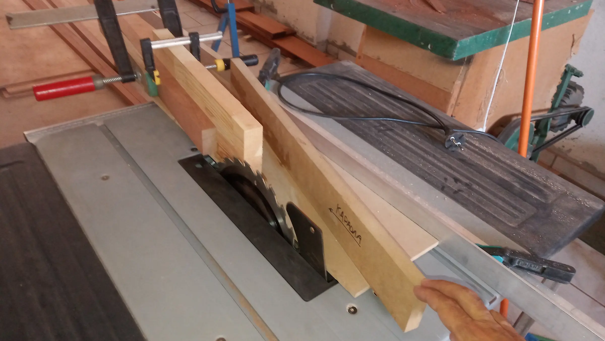
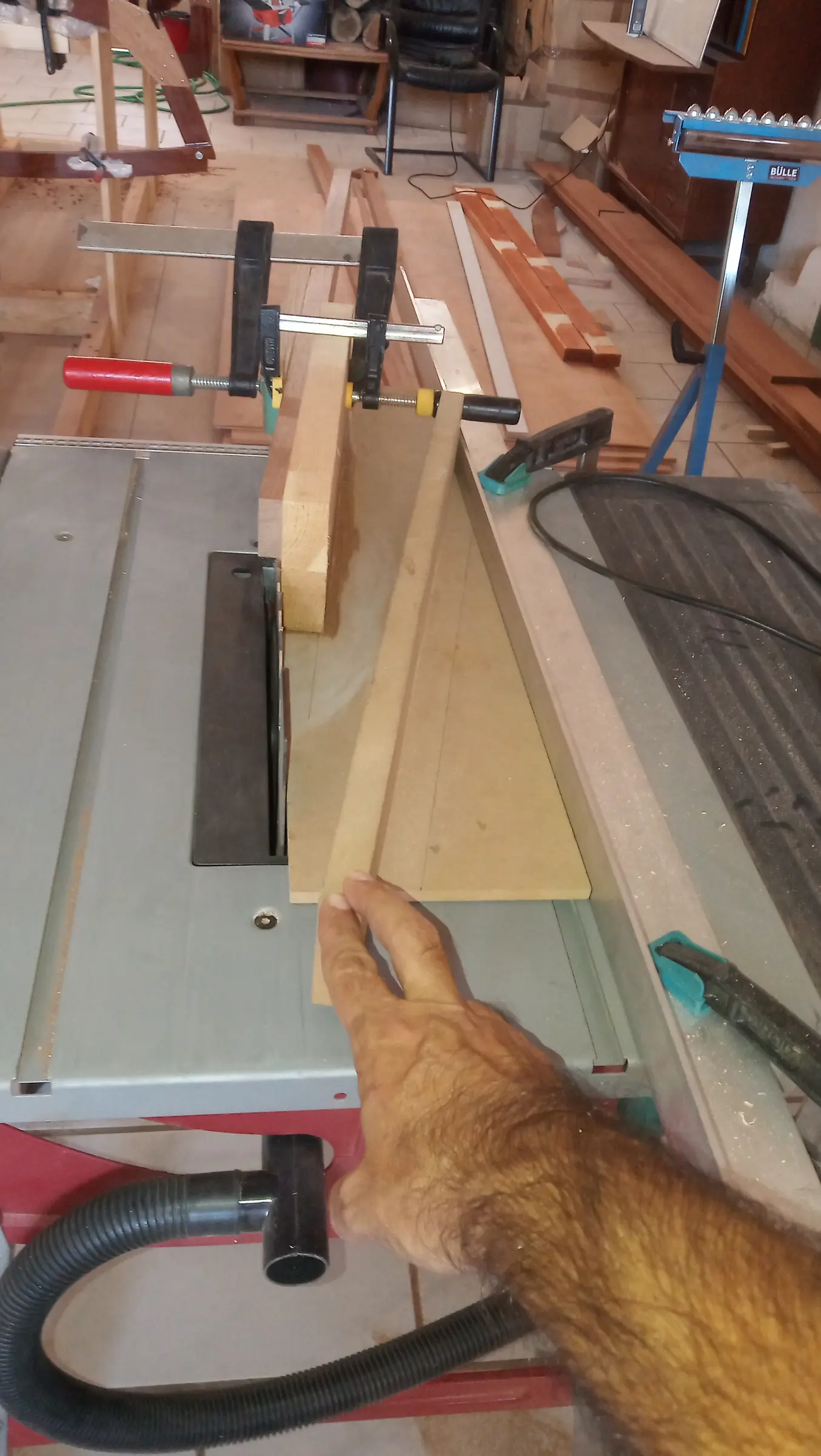
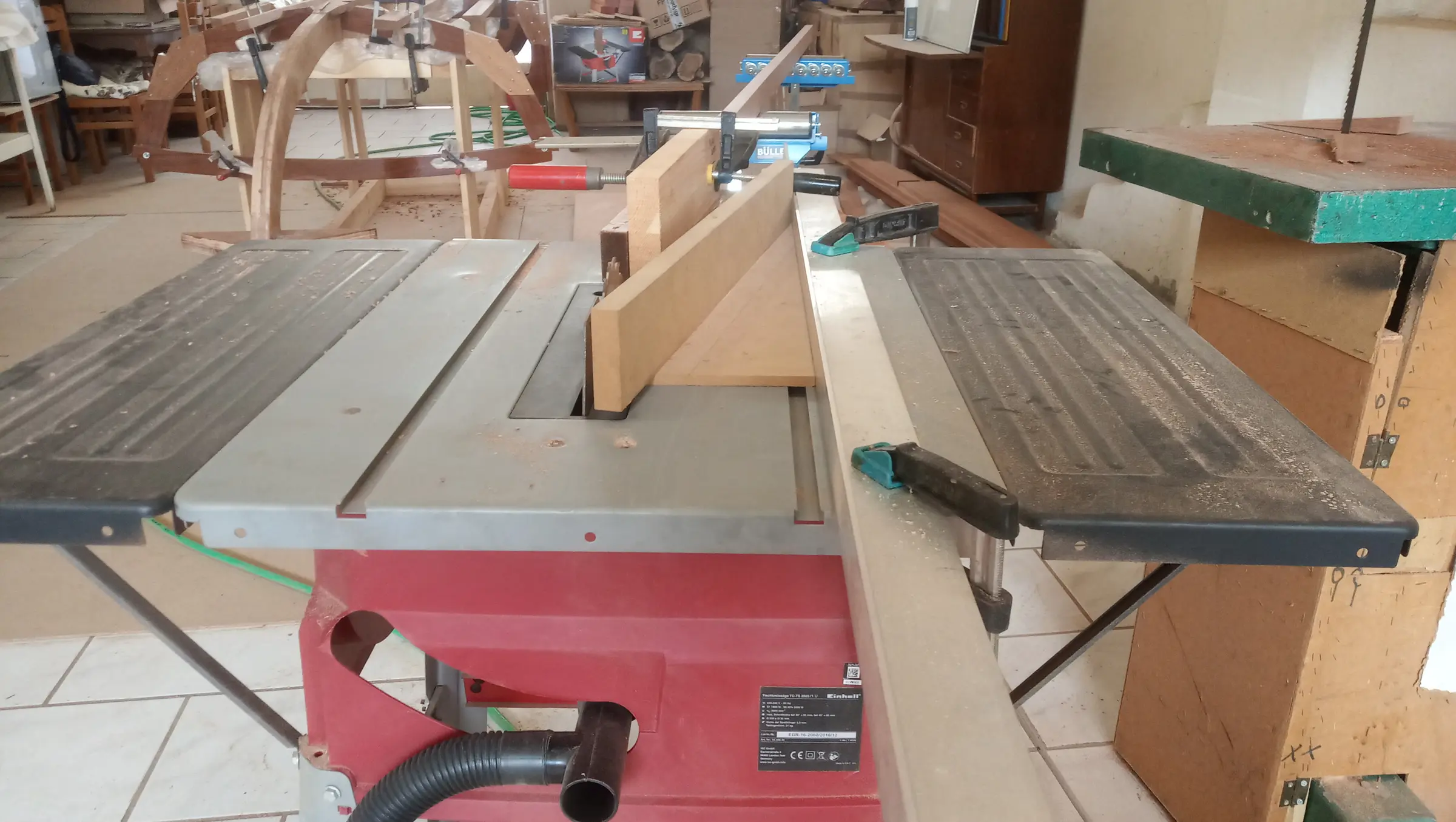
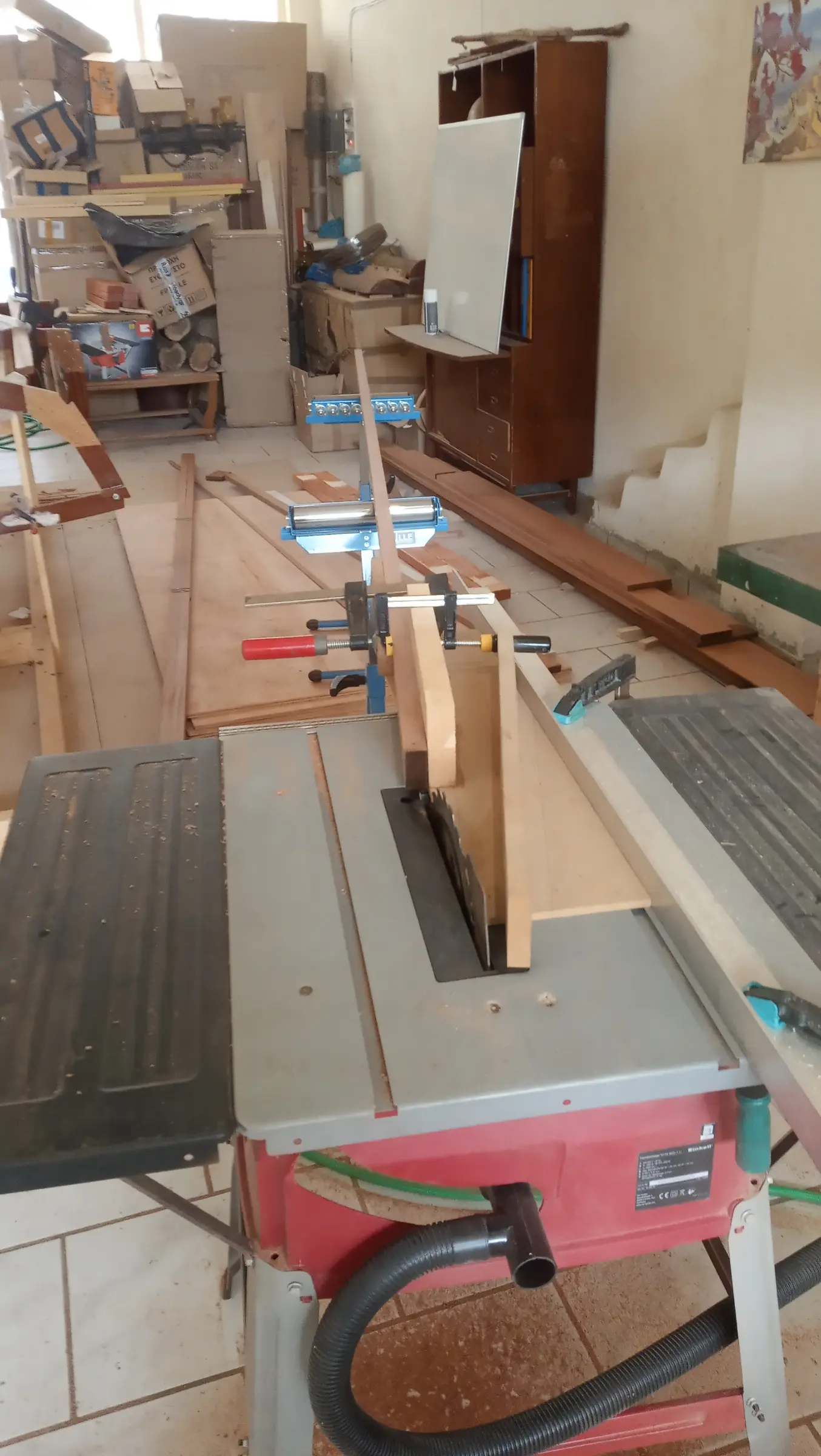
For the cut I used the table saw with the help of a jig I made. In fact I had built the jig some time ago for gluing the binding onto the necks of musical instruments, and that was a 13 degree joint. A second fence was added at 7 degrees for the scarf joint.

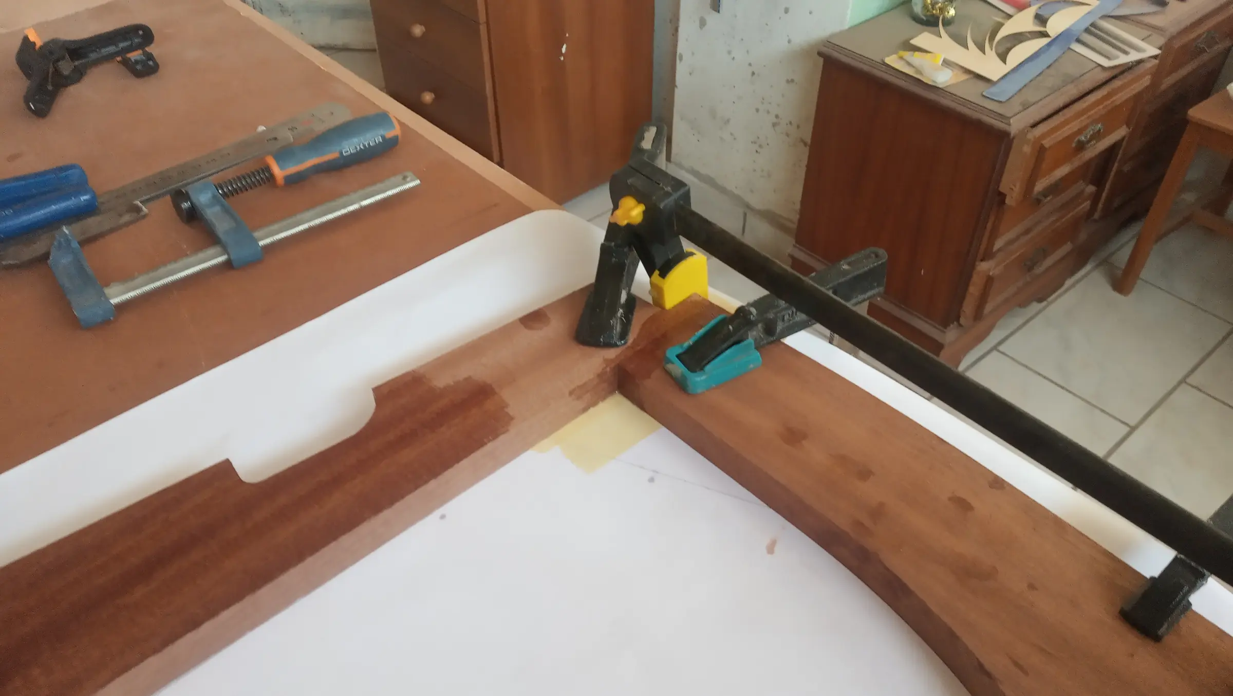
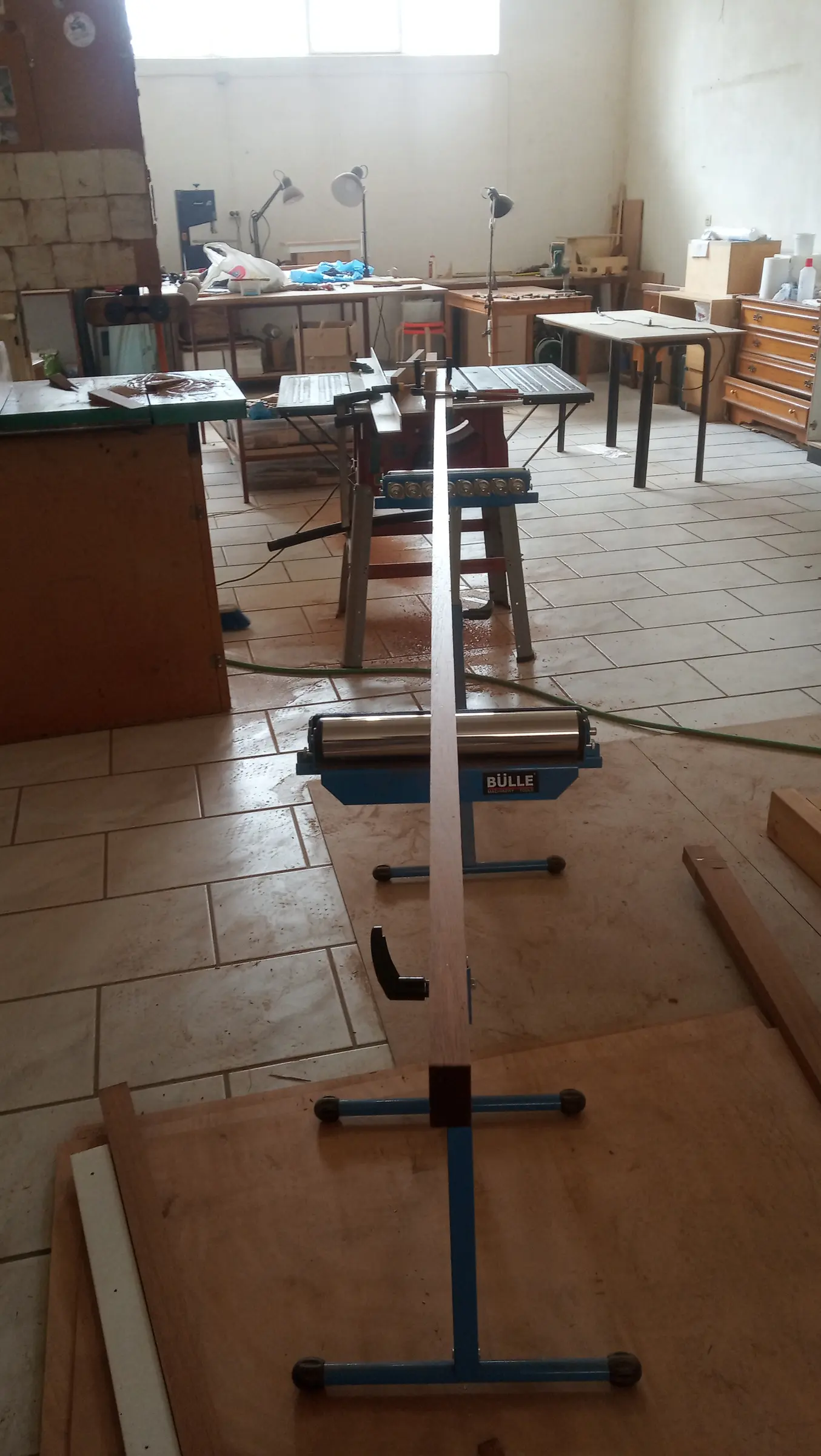
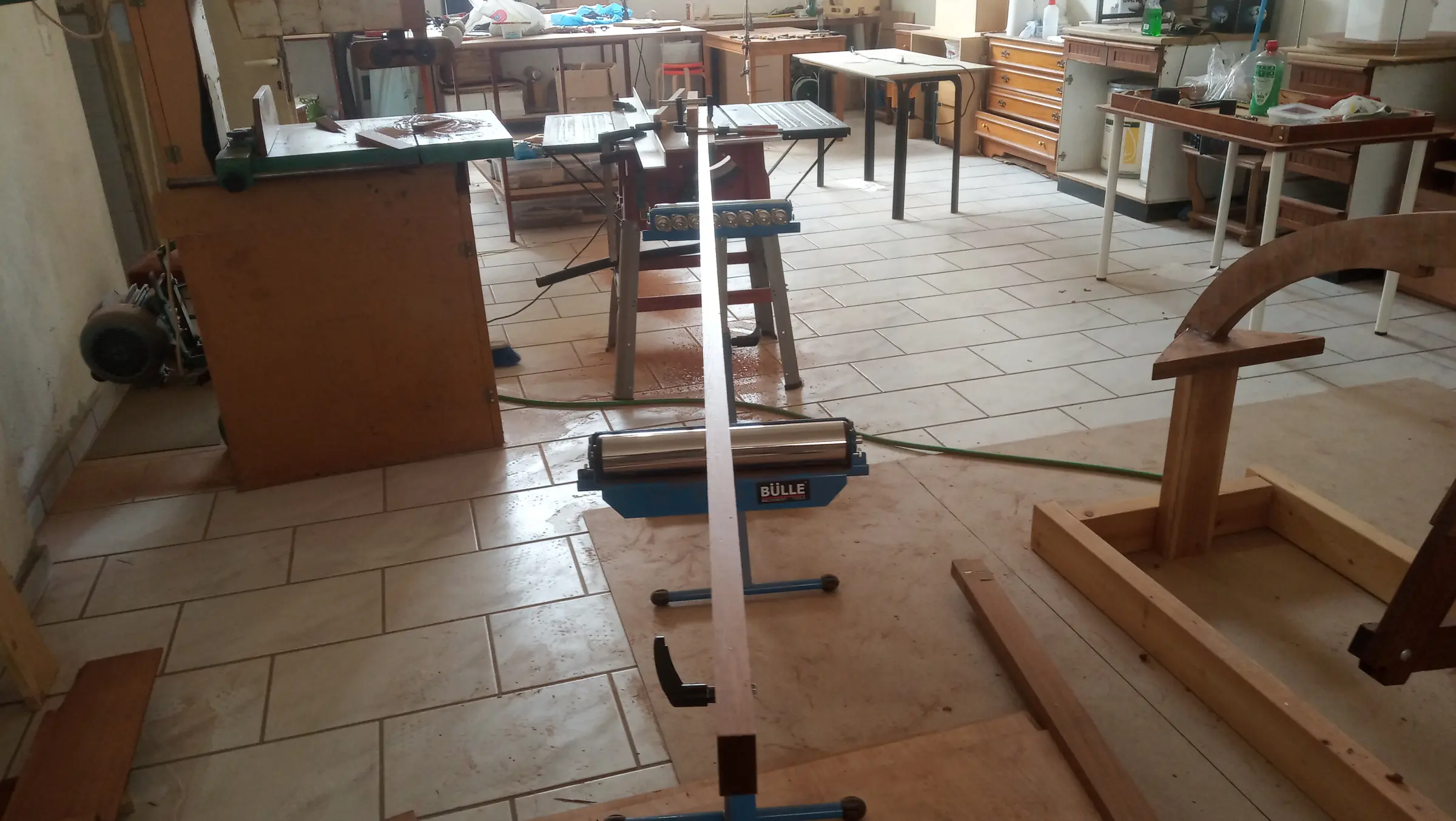
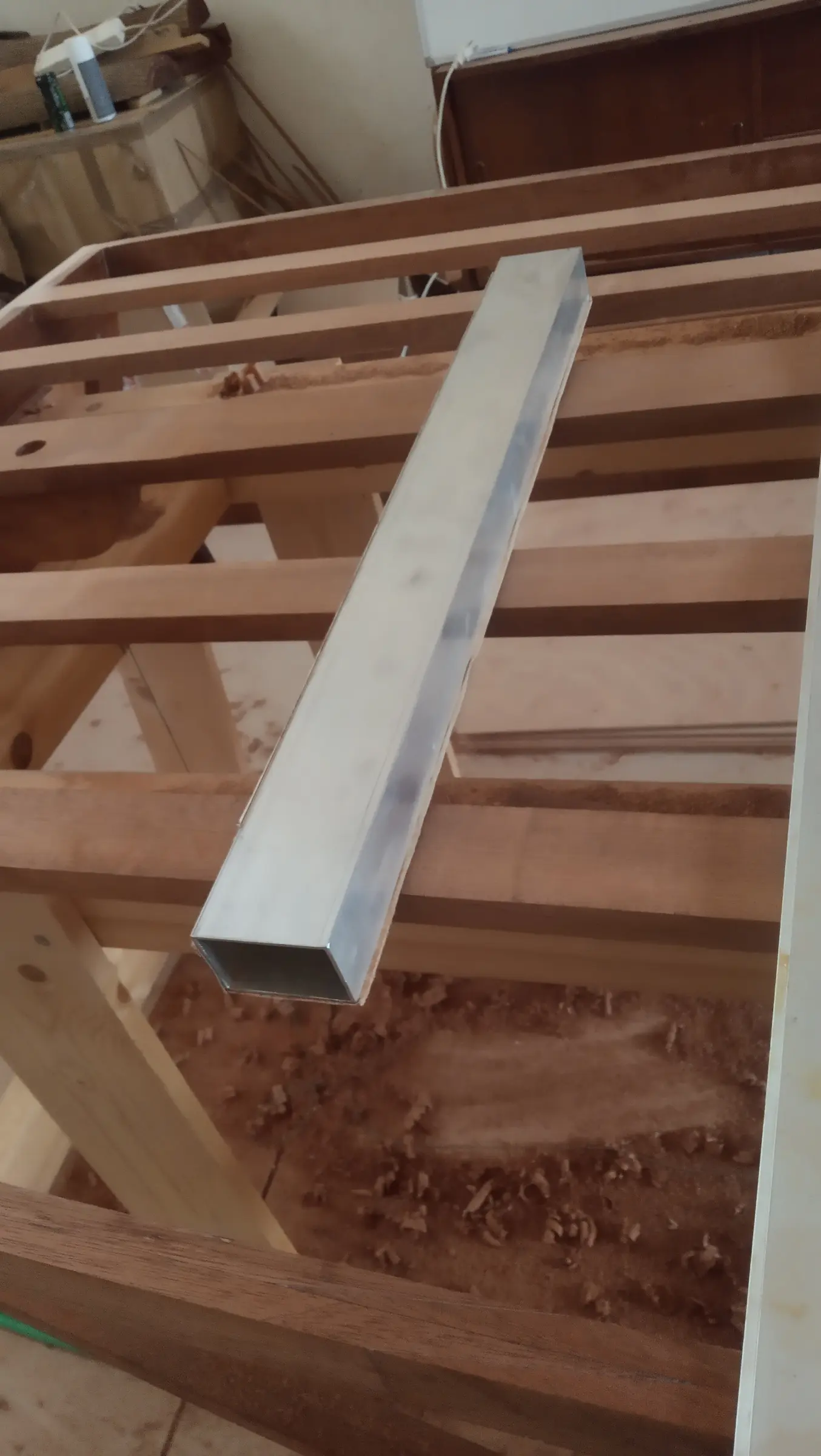
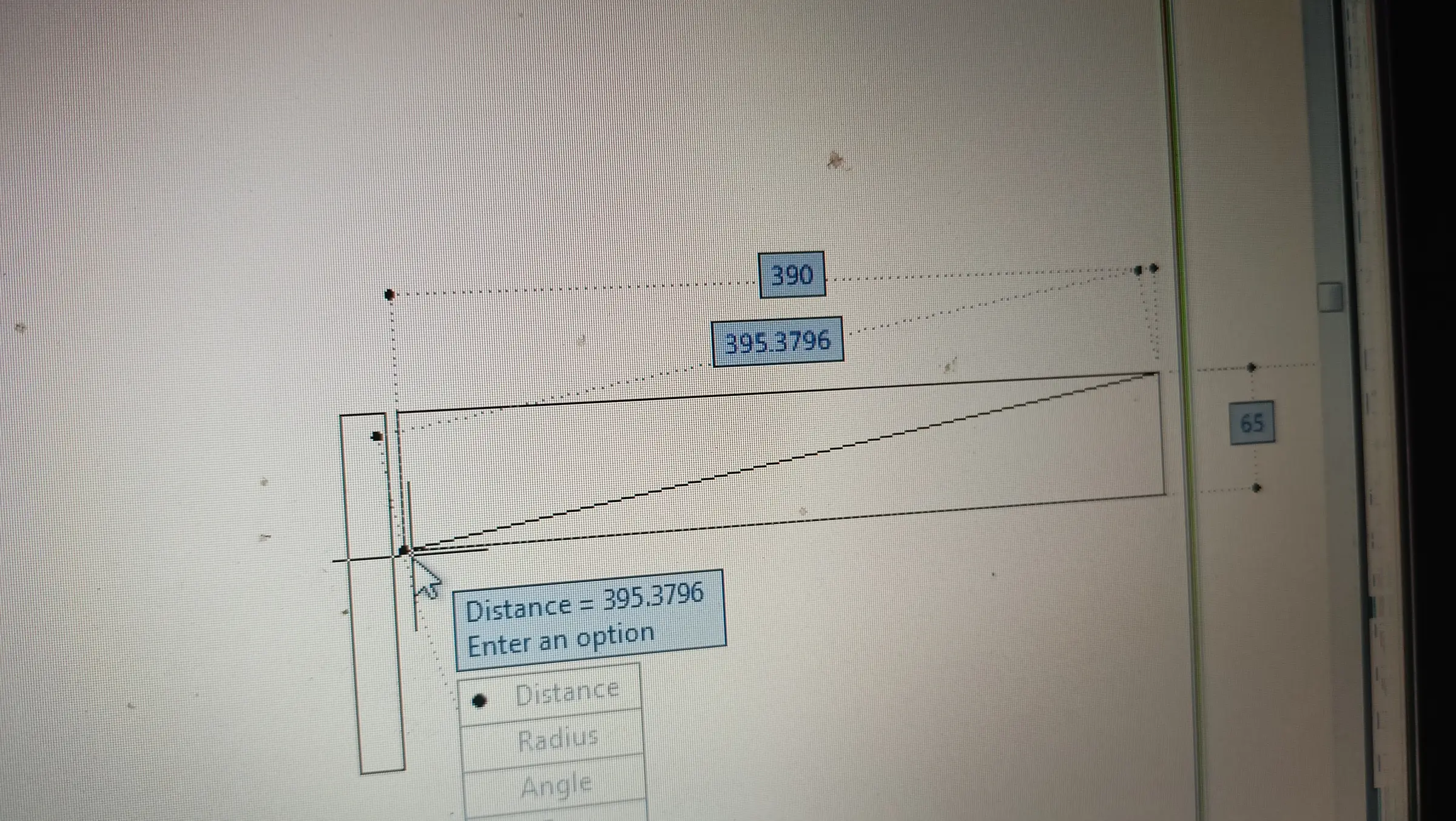
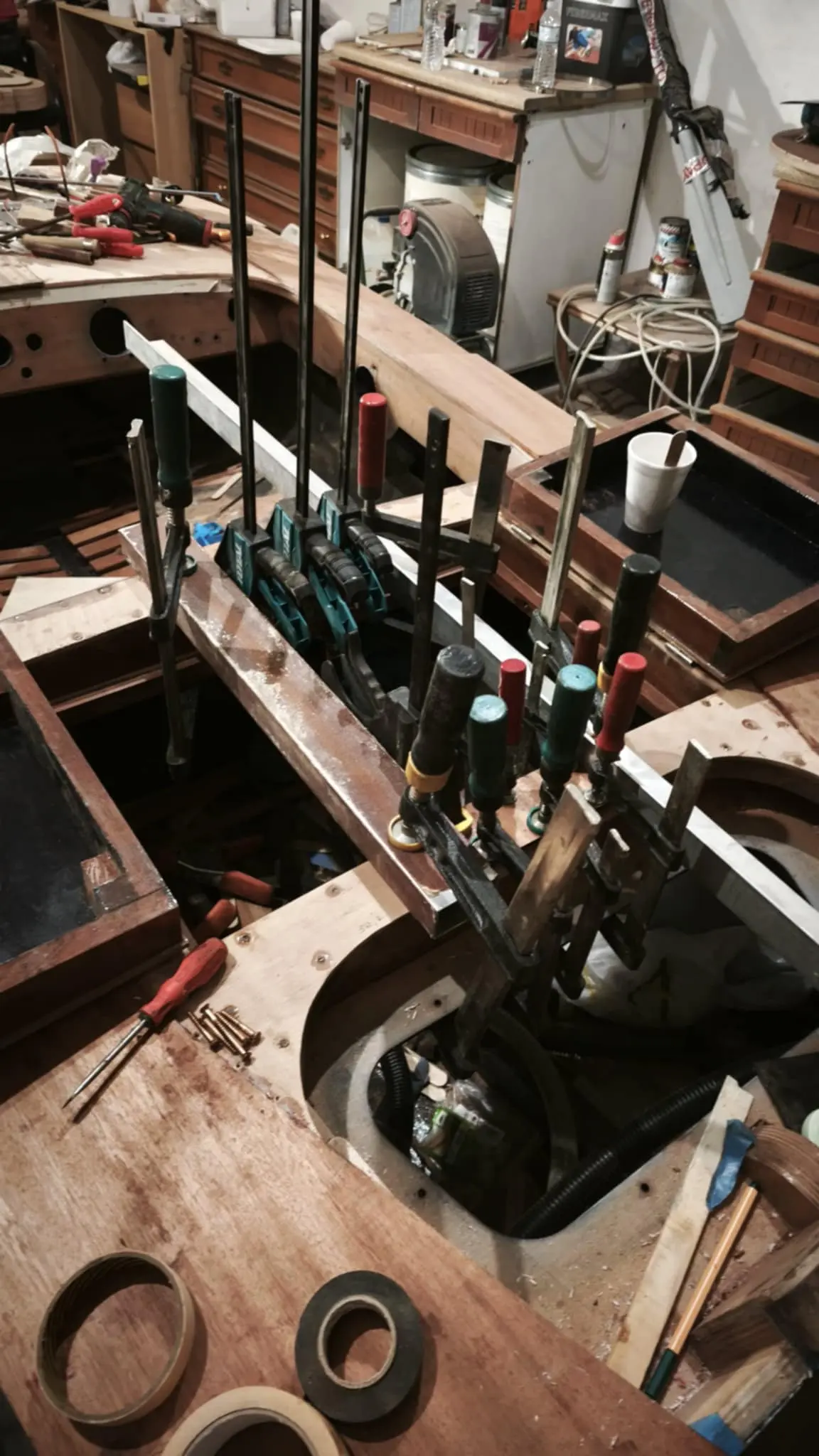
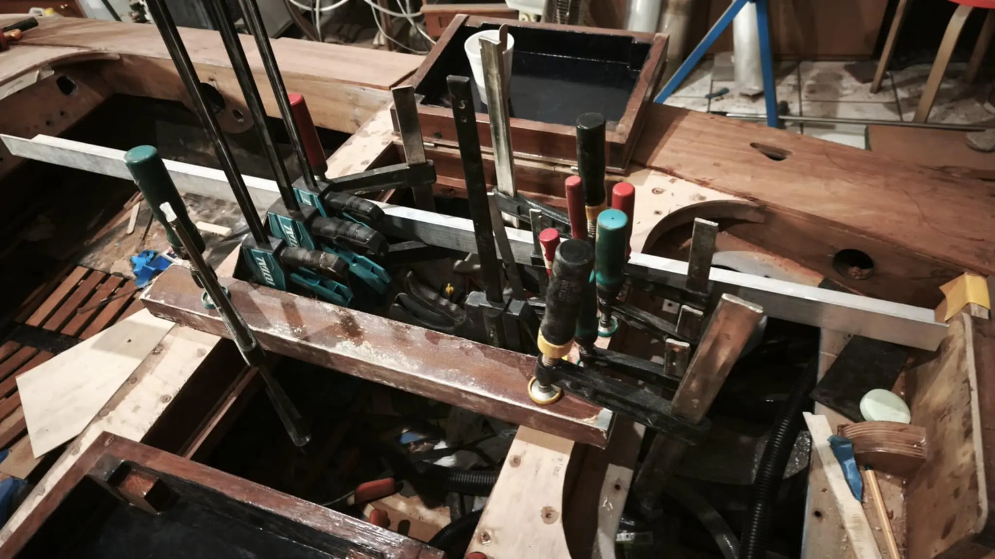
Once the pieces were cut they were sanded while clamped together, to take out the imperfections of the cut, and then glued using an aluminium angle to hold them straight, along with clamps.

Next the notches had to be shaped so these long pieces would sit down and glue in place.

All of these notches have been cut square along their length. However, because these pieces are going to be bent, they land in the notches at an angle.

At the first frame the pieces are still opening out, while at the second they are closing in. This process took a fair while, testing with some thin battens that bent very easily.

Once the twisted pieces had been left clamped and glued for 7 days, so the resin could reach its full strength, the clamps came off and screws went in for extra strength. I ran resin into the holes drilled for the screws. Finally the carriage bolts went into the keel, in the same way as the earlier ones.


62.5 h

Steam bending and gluing the chines and sheers

For the side timbers that tie the transom to the frames and the keel (the chines and sheers) I again used sapele and sipo, bought at 8 and 6.5 cm thick. The dimensions are 355 x 32 x 16 (two pieces glued together) for the sheers and 340 x 45 x 25 for the chines (a single piece, which in the end I could not bend. Read on).

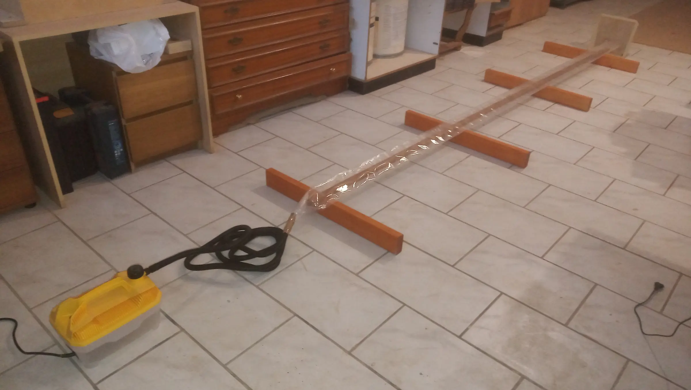
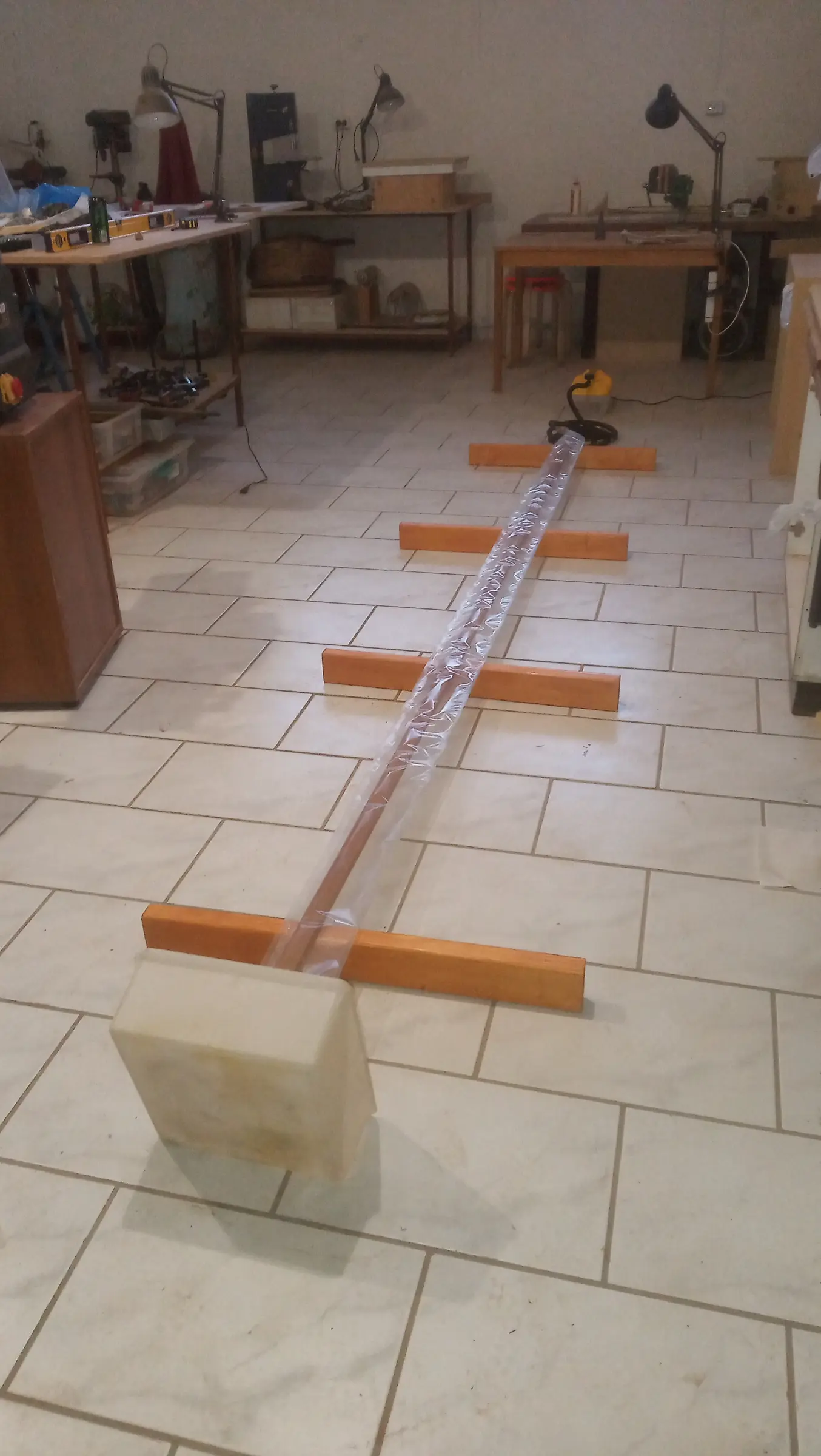
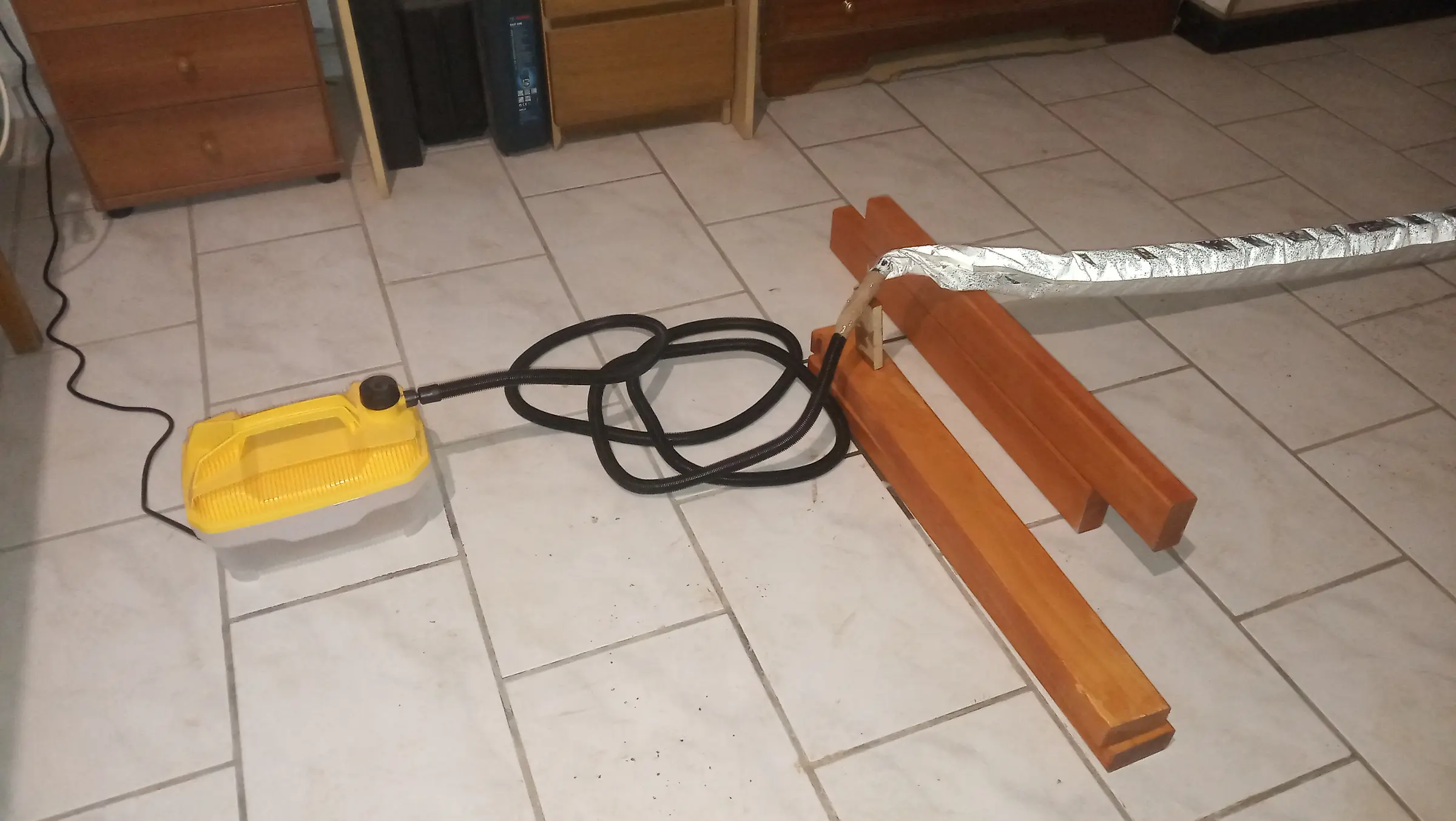
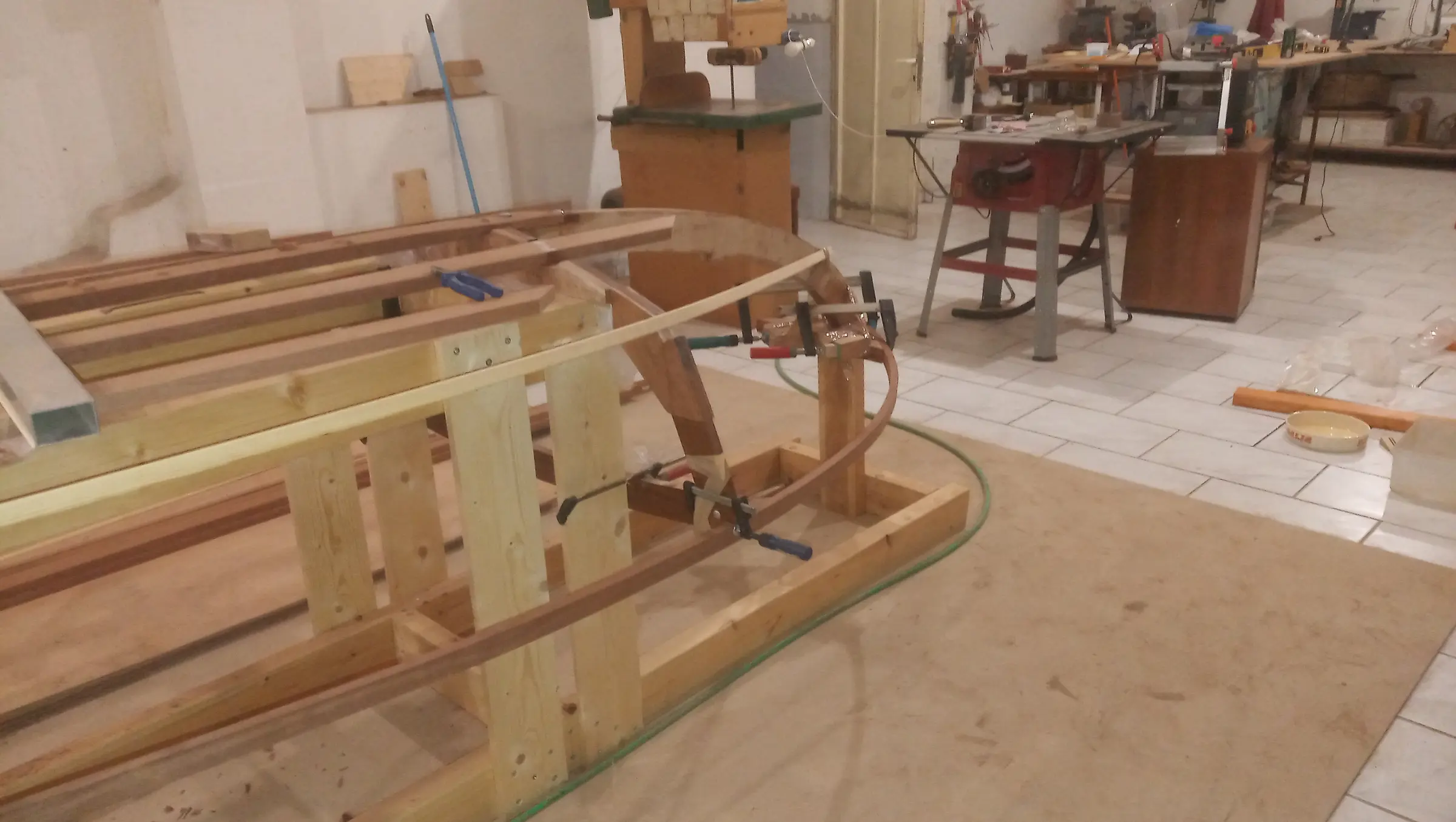
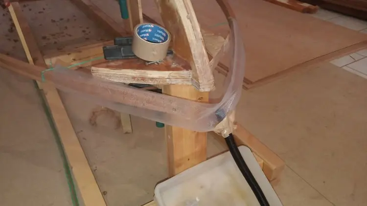
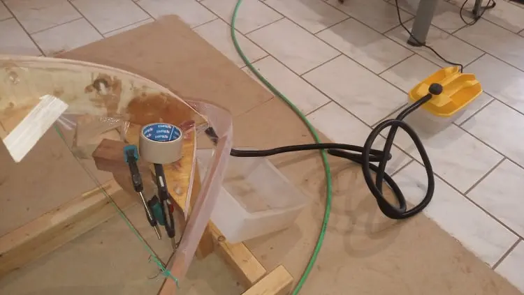
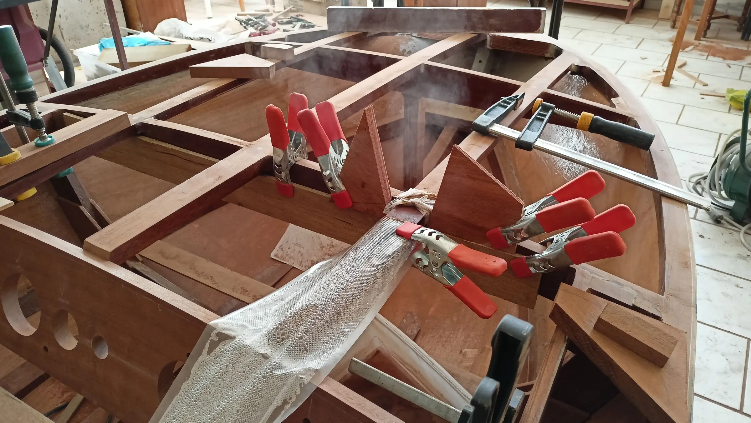
For the bending I used a steamer bought from amazon.com for around 60 euros. I did not make a wooden box or a PVC pipe to hold the steam, I used food packaging bags 5 m long instead. The process I followed is shown below. The bag was closed at one end around the pipe while the other was left open so I could drain off the water as it condensed. Small holes were made in the underside of the bag so water could escape there too, but the damp seems to have stuck the walls together and it did not drain from those. Every so often I lifted the whole arrangement slightly so it would run out of the end.

A few notes on timing. The theory says an hour is enough to bend an inch of timber (about 2.5 cm). Of course a lot of things affect that (the equipment, the species of wood and plenty more, I imagine).

I filled the steamer almost to the top with water (half a finger below the max) and plugged it in. Fifteen minutes later steam started coming into the bag. Four minutes after that it had filled to the far end and steam started escaping. After about 20 minutes I decided to take some water out, I reckon a finger and a half to two fingers, because I thought it would boil more easily. The steamer switched itself off exactly when I was going to switch it off anyway (the water inside reached the limit) after 50 minutes. Even though the timber was 1.6 cm thick and the theory says 35 to 40 minutes would have been enough, I left it a little longer to be safe.

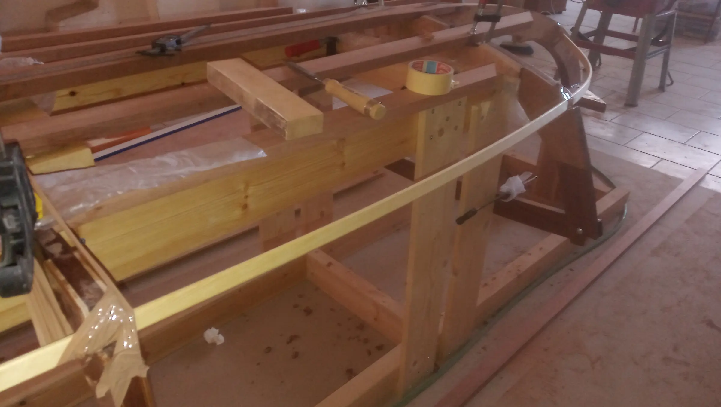
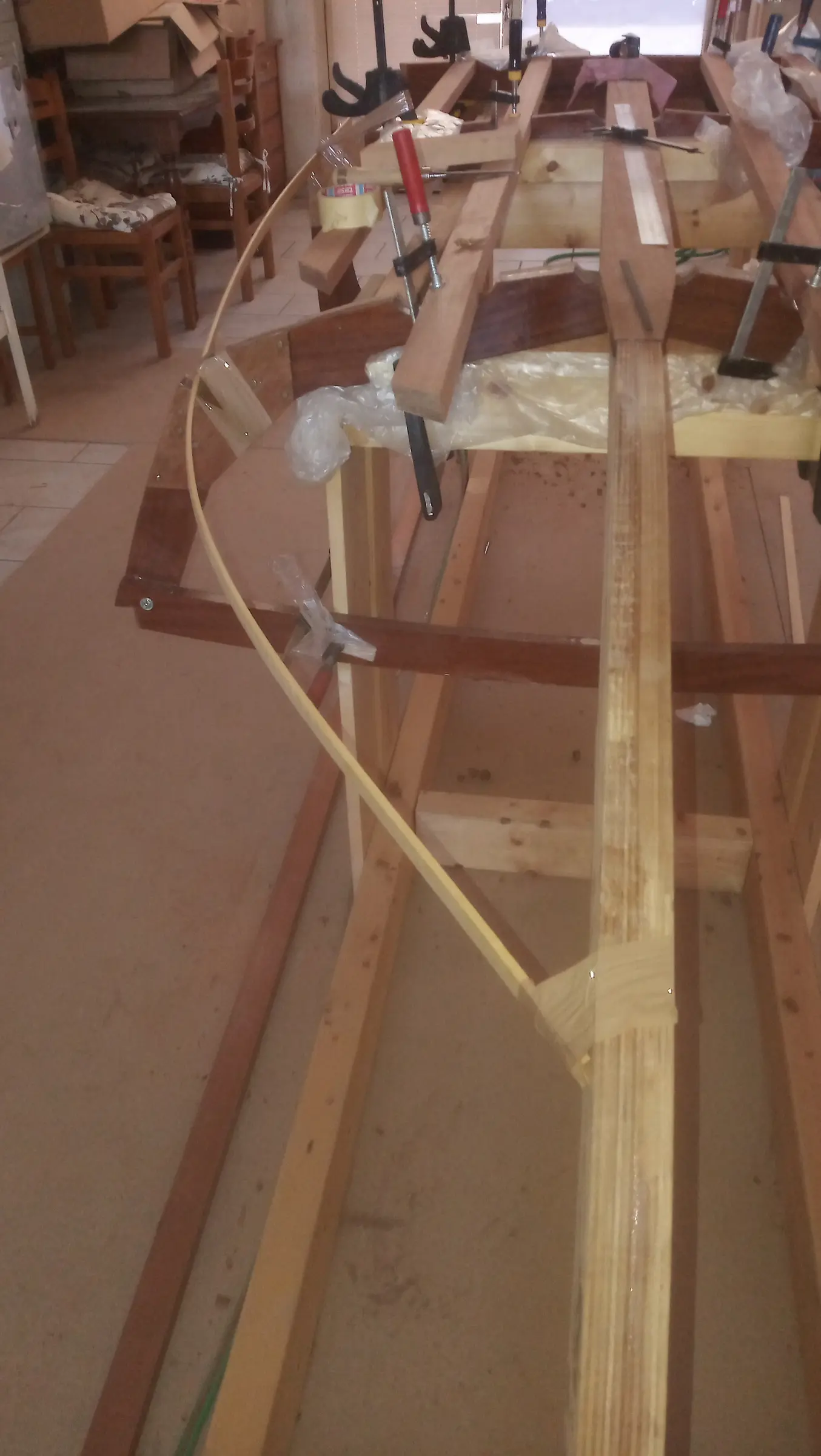
The bending started at the front and worked aft. The day before I had spent a little time working out how the bent timber would be held onto the rest of the boat. I tacked on some wedges so a clamp would have something to grip. In some places it was very easy to get hold of.

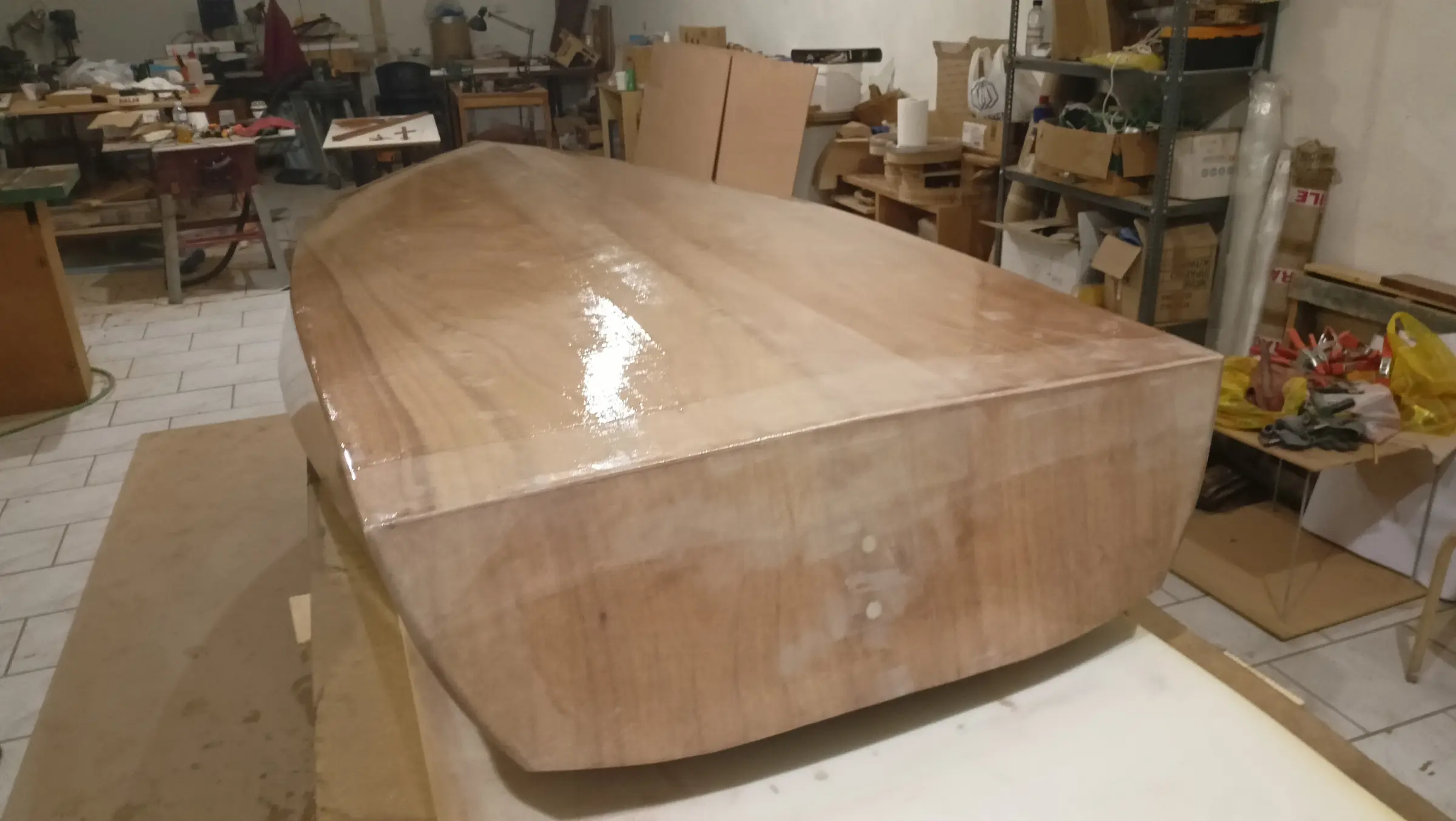
The final result is shown below. I have left the timber slightly long so it can be cut to its exact length later.

A few short videos of the process. Unfortunately there was no way to film the actual bending, as there was nobody else there.

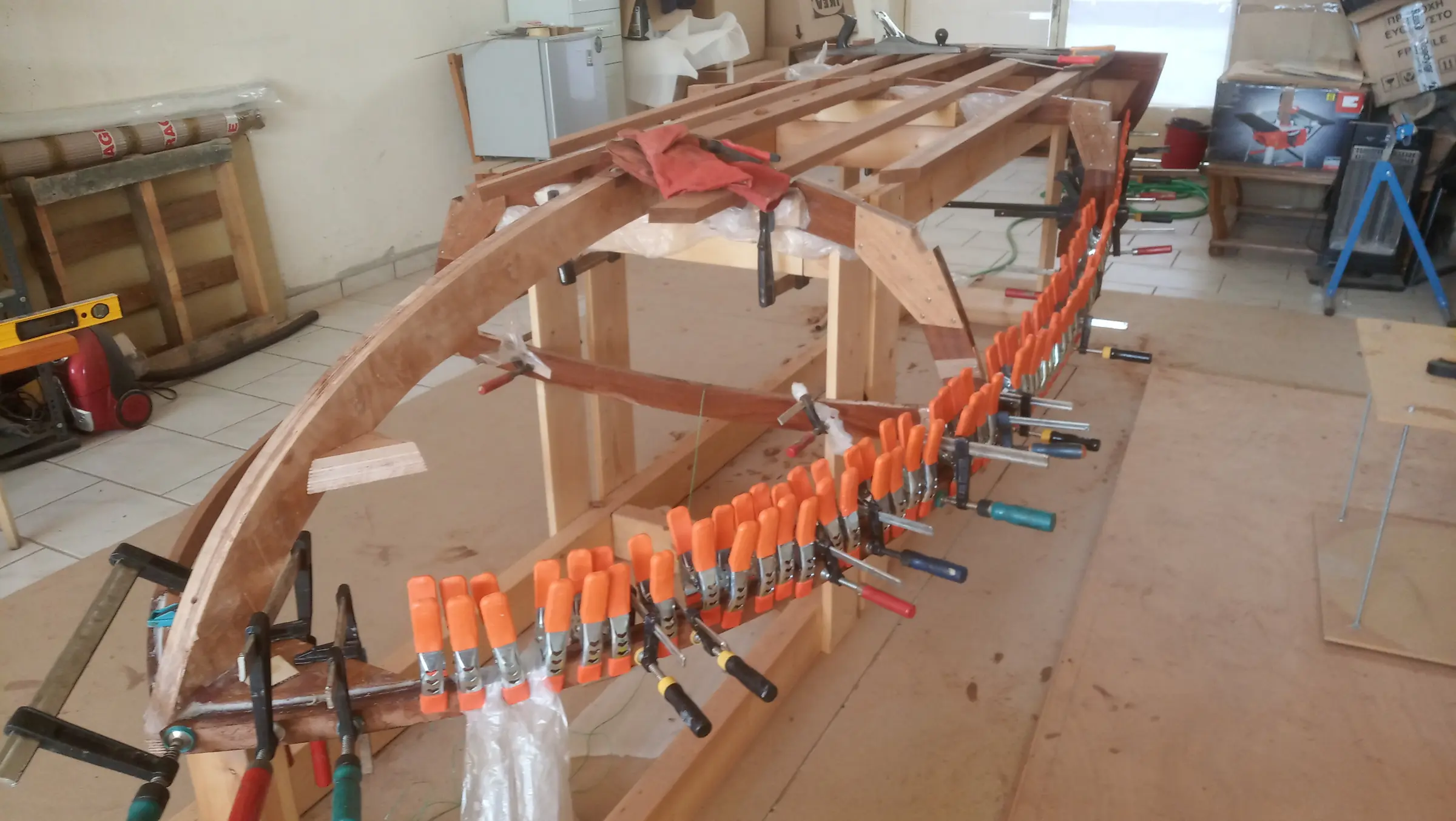
The pieces were left clamped up to dry and take their shape.

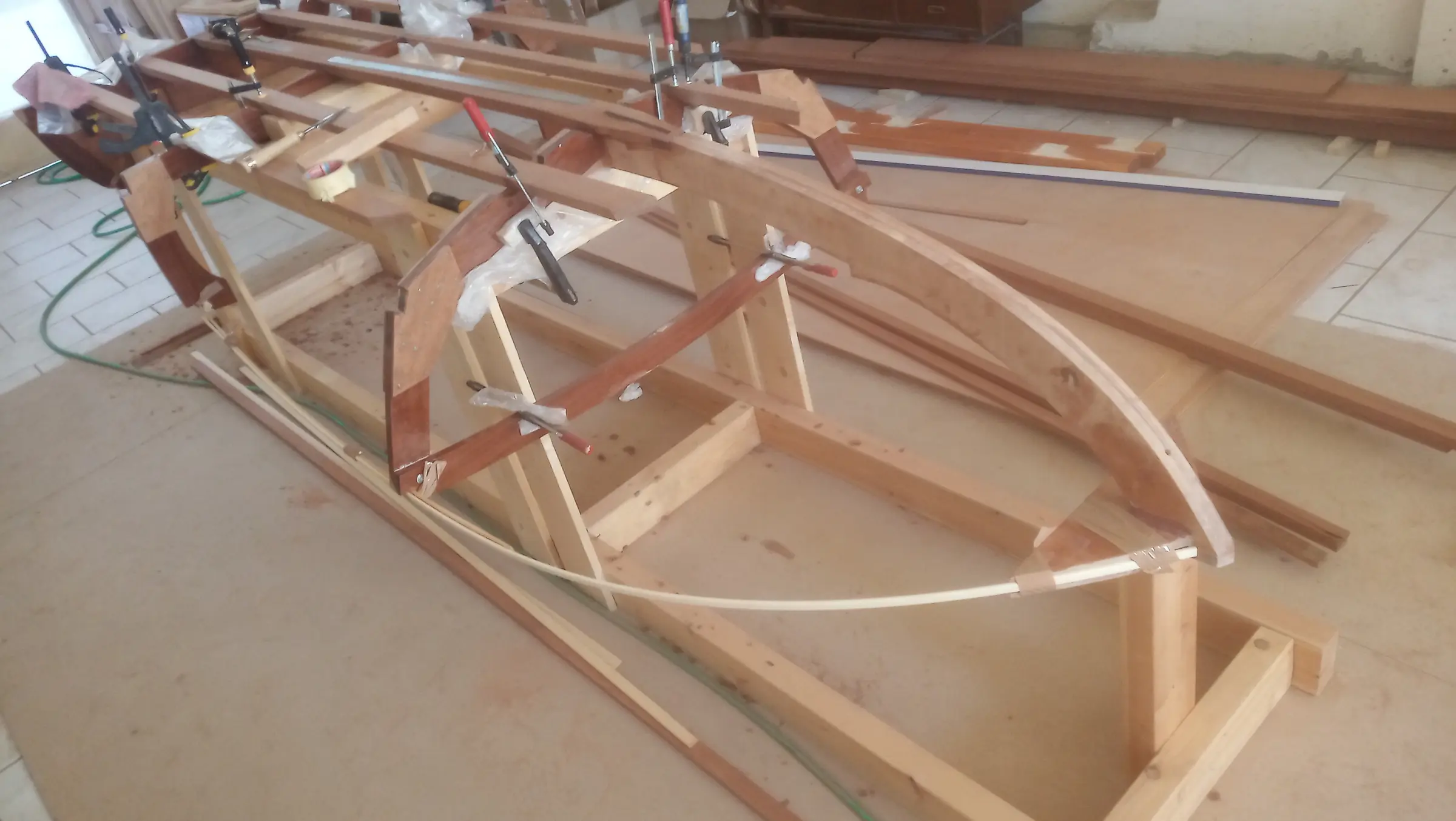
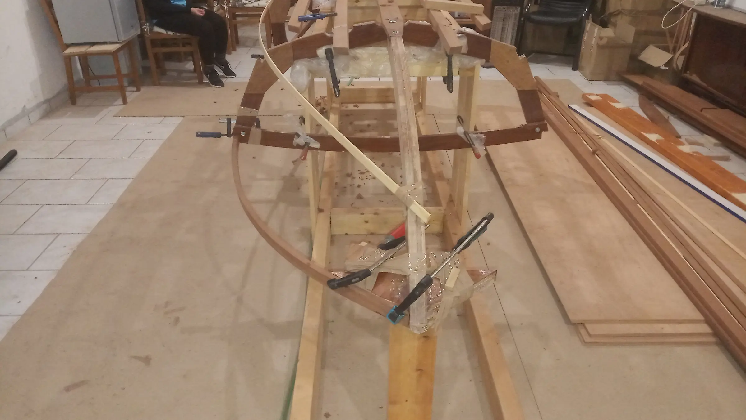
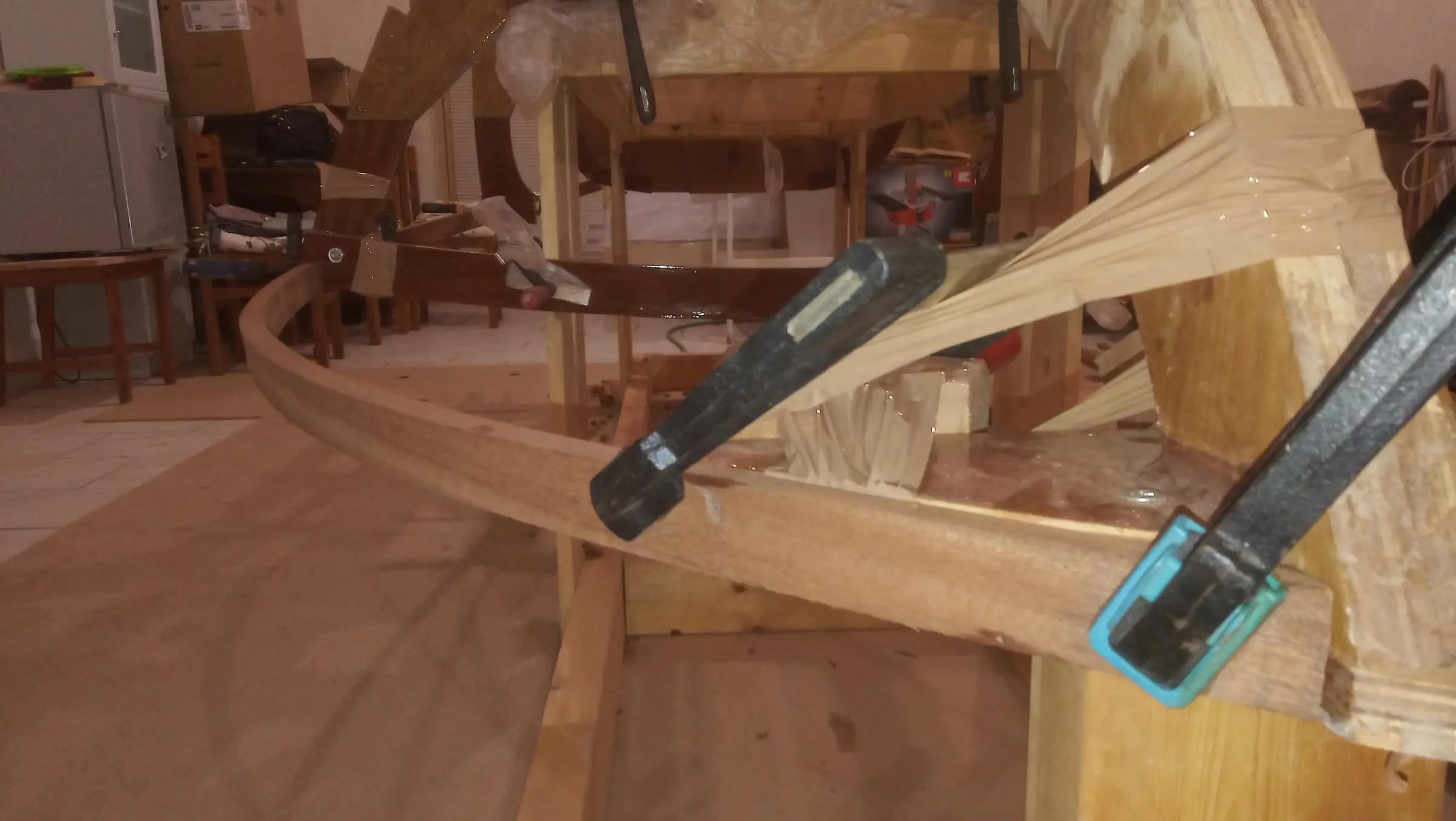
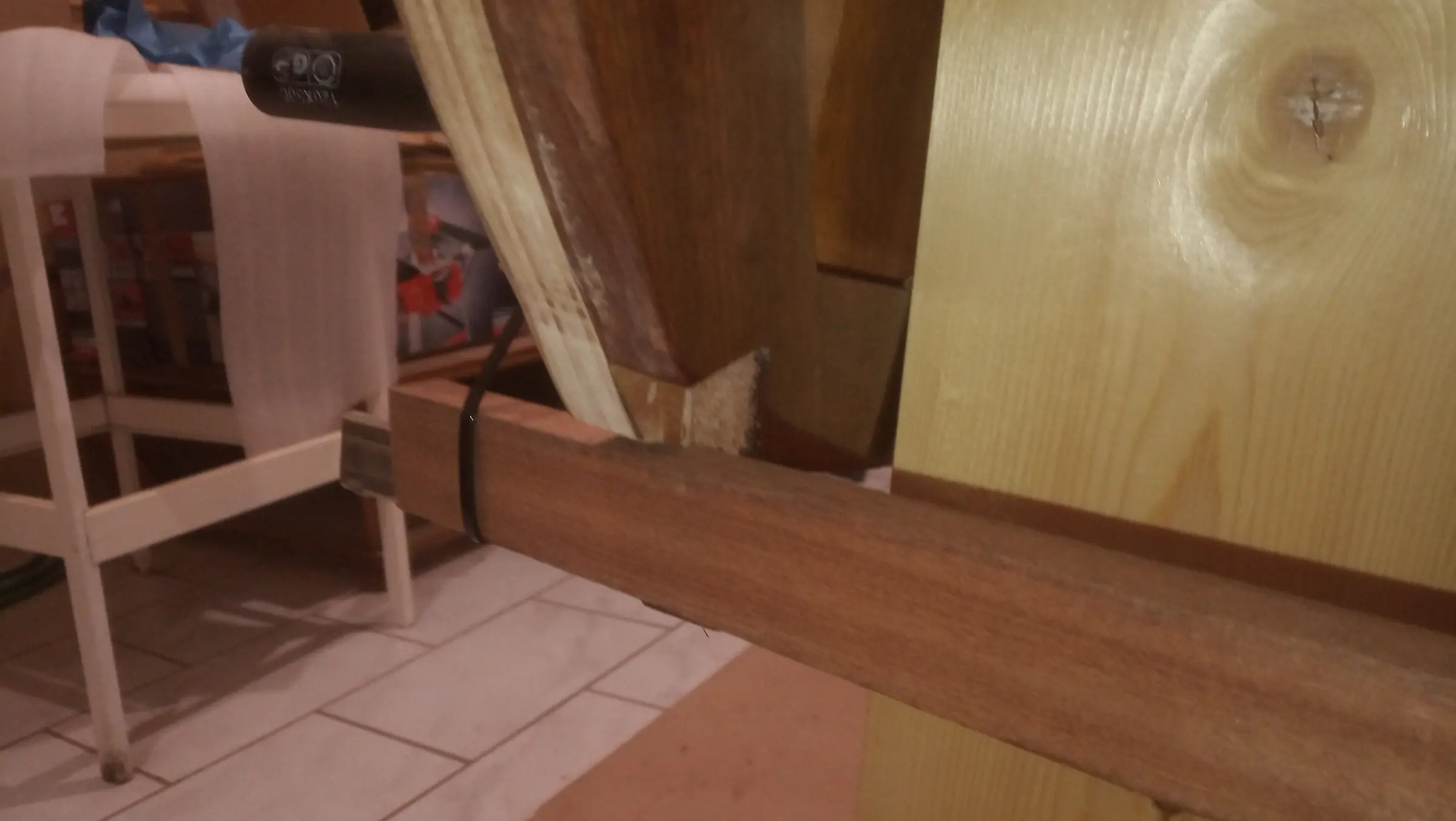
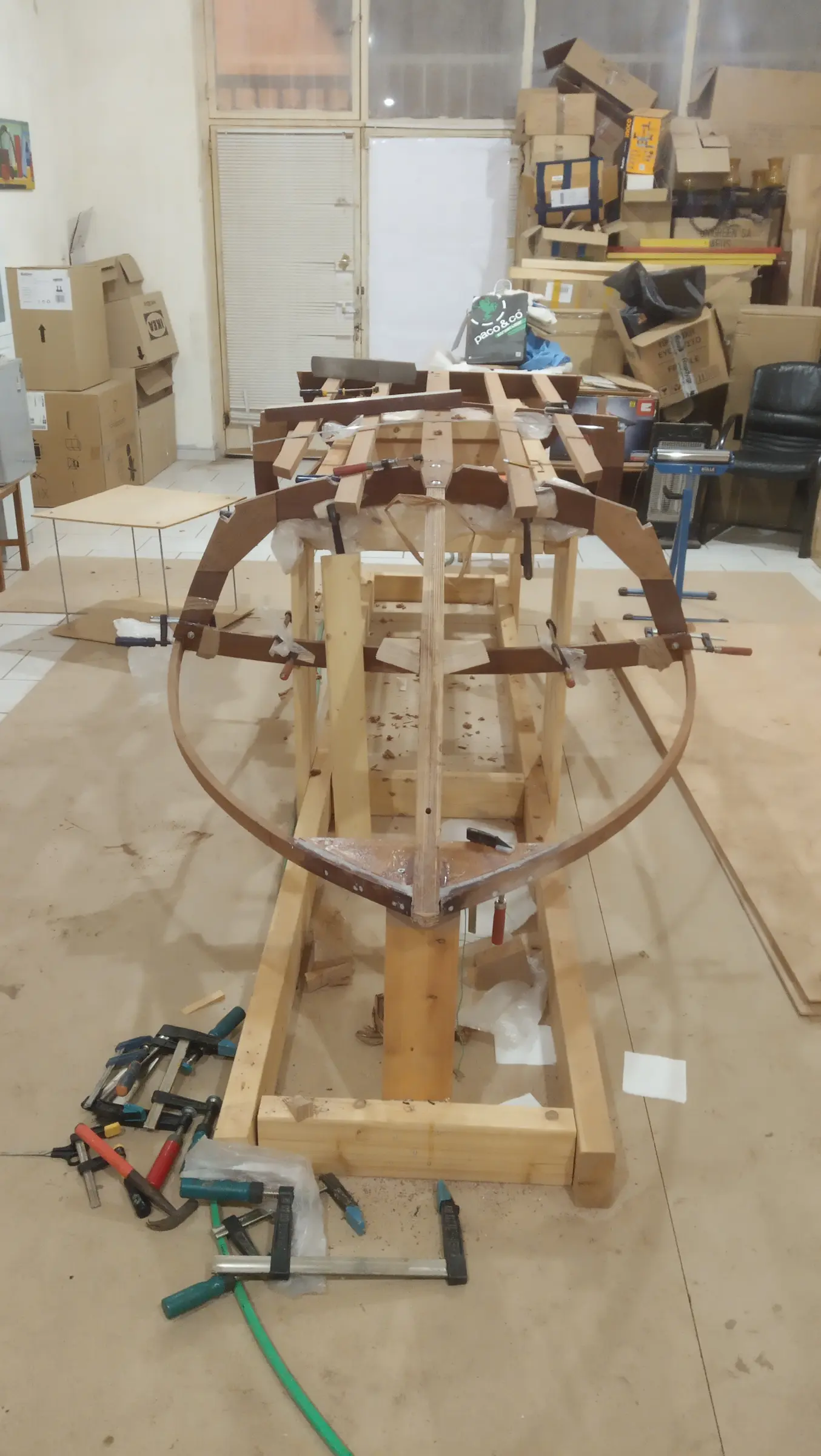
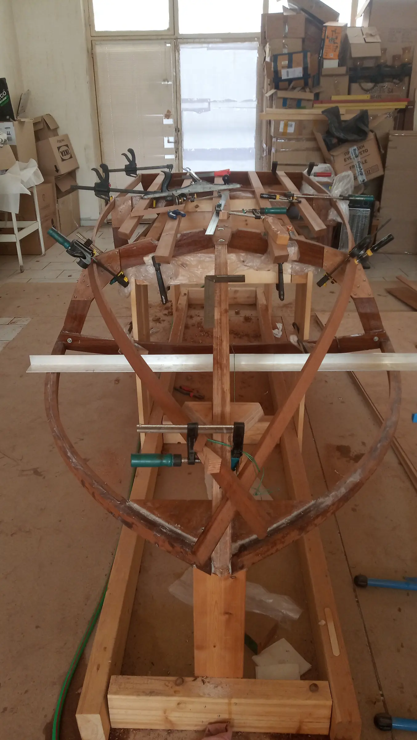
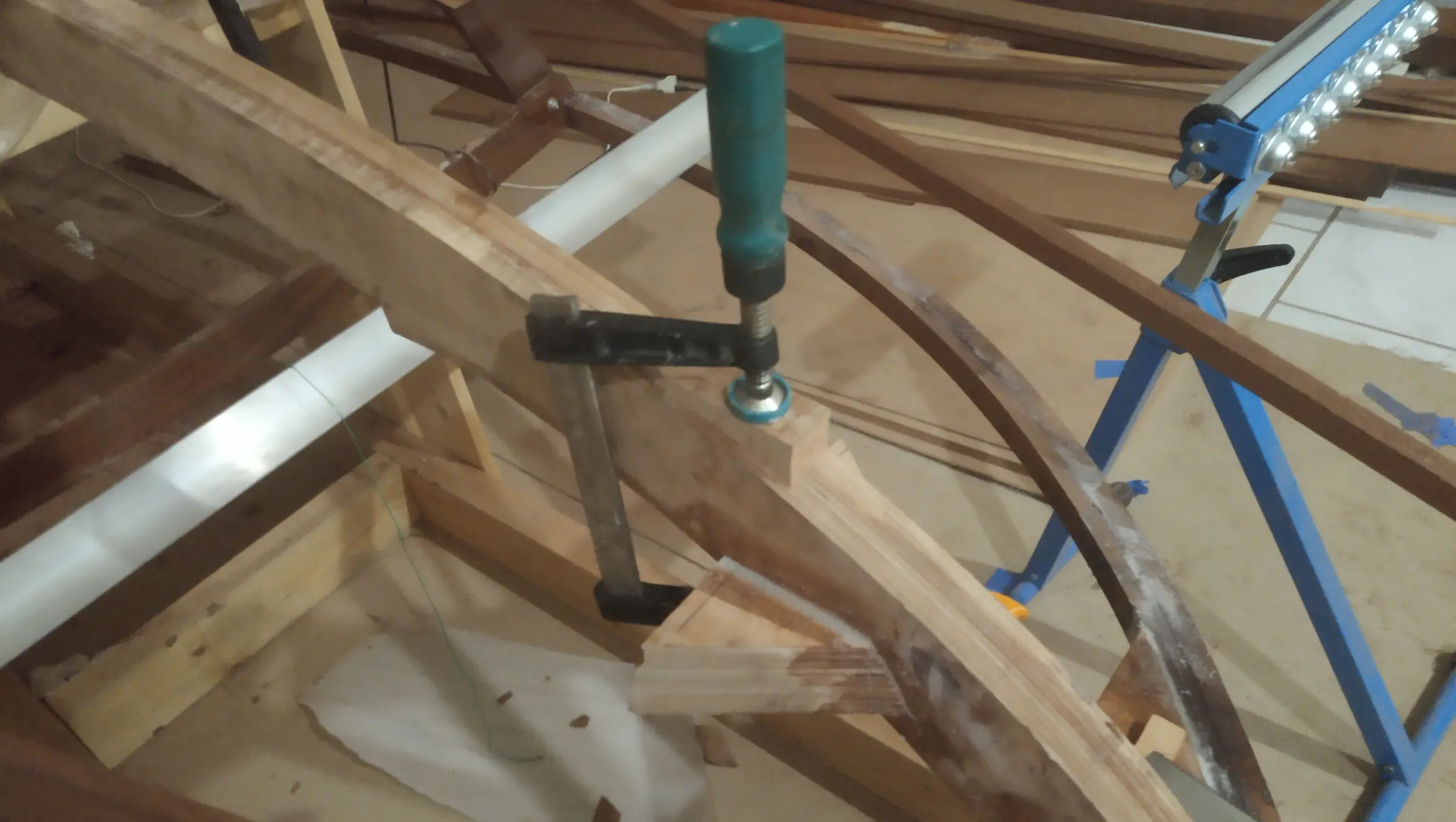
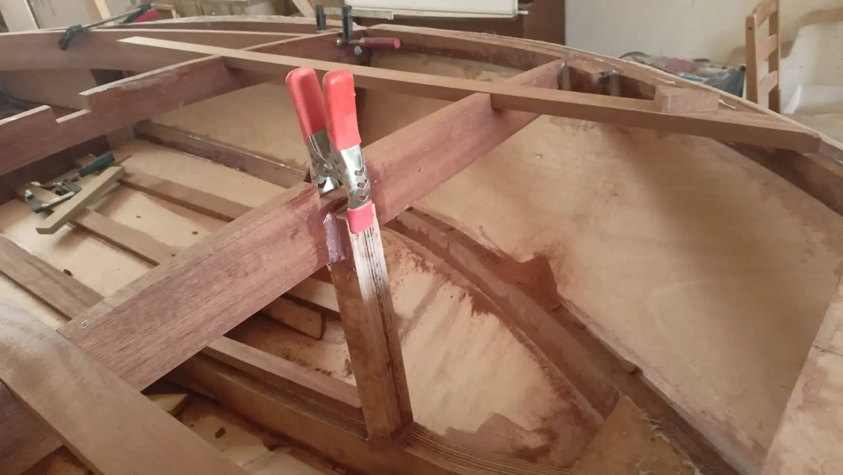
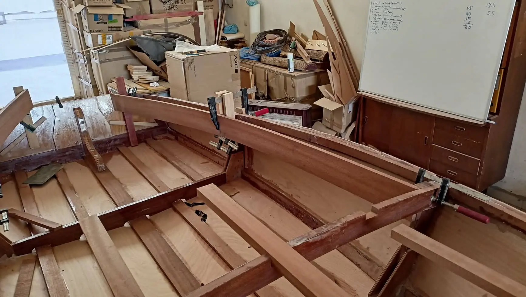
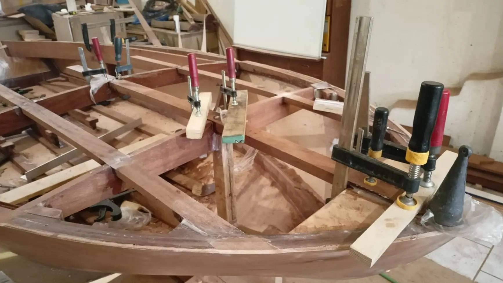
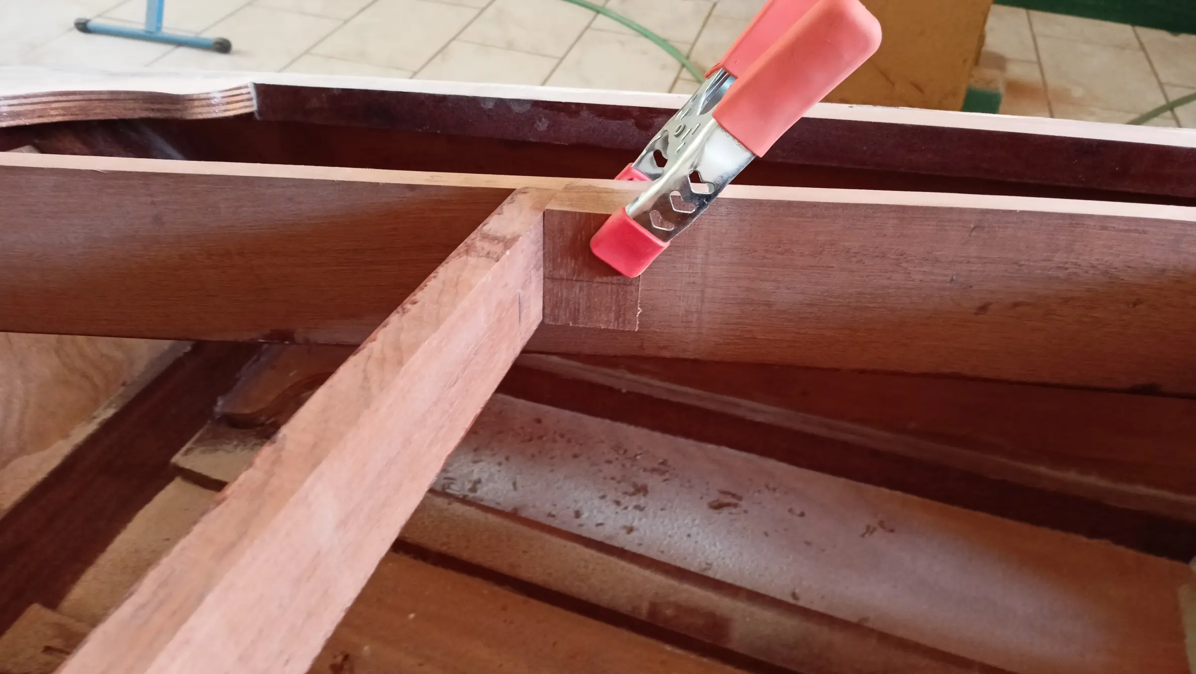
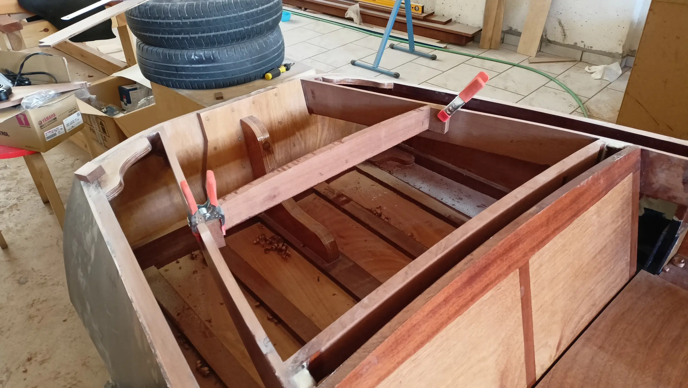
I found that the only way to get them to sit perfectly against the forward face was to clamp them there first, with all the other clamps removed, and twist the timber to follow the imaginary "straight lines" made by the forward triangle. (I tried to bend the forward sections further on their own but could not get a good result.) The forward part was glued first, on both sides. That was so I could make small adjustments and get the structure perfectly symmetrical. Some photographs of that glue-up and of the second attempt at more bending.

They were then glued at the remaining joints on the frames and the transom.

Before gluing at the forward frame they were tacked in place so I could check the two curved pieces were symmetrical. Using a string line I pulled the centreline that splits the boat down the middle. Checking it, I found it is almost symmetrical about that axis (it is out by one or two millimetres, and those get corrected when the timbers are faired) but there is a problem on the z axis. One piece, even though it was glued exactly the same way as the other, sits closer to the floor. The difference runs from zero (at the frame and at the triangle forward, obviously) to around 7 millimetres somewhere near the middle. It is a serious problem, because when the timbers are faired they are cut at an angle and end up triangular. If one is at a lower level then in the end we will have a deck that is not symmetrical. Say by a centimetre, but it will show because of the shape of the final pieces with the stripes.

Once I have glued the second run of timber I will try to fair them on all three axes, measuring the distance from the floor and from the centreline every so often (every 15 or 20 cm). If fairing takes more wood off the low side then a third piece will have to be glued on top to build it back up.

Once that is done I will start fairing for the plywood to be glued on.

There is another solution that corrects the problem visually, which will be used if the above does not go well. Essentially, if it does not come out symmetrical in the end, the plywood and the striped timbers on the top are glued perfectly symmetrically and a wooden fillet is run underneath, around the perimeter. Where the plywood overhangs, the fillet is left slightly thicker. I will explain it better if the problem actually shows up (it has shown up for most people who have built this boat, and I do not expect to get away with it even though I know about it).

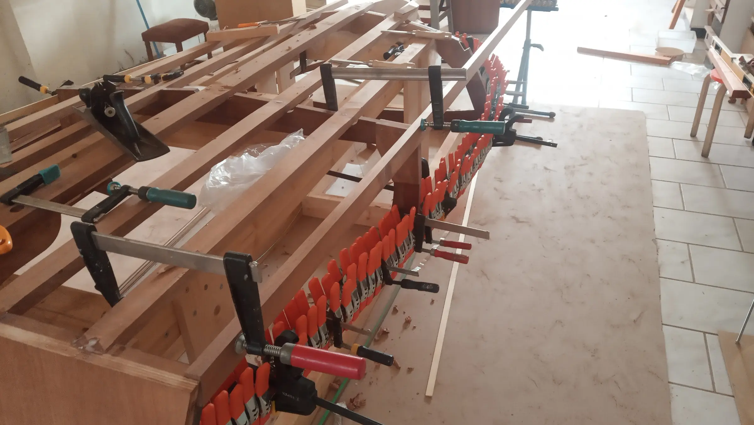
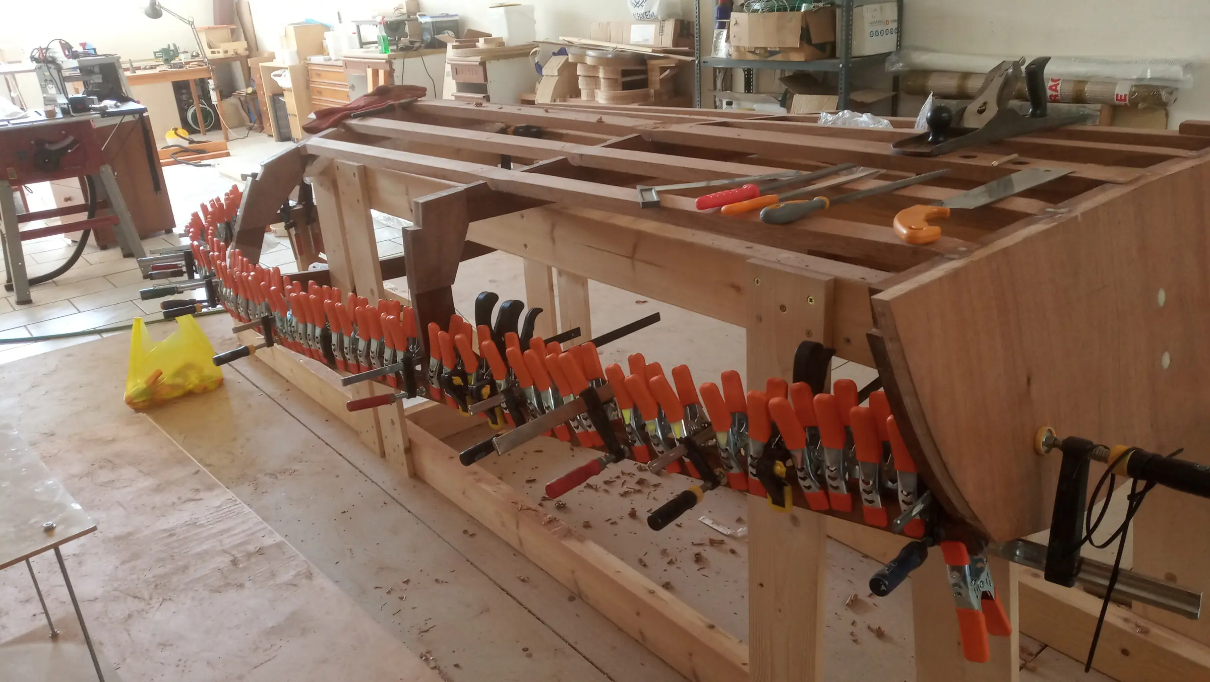
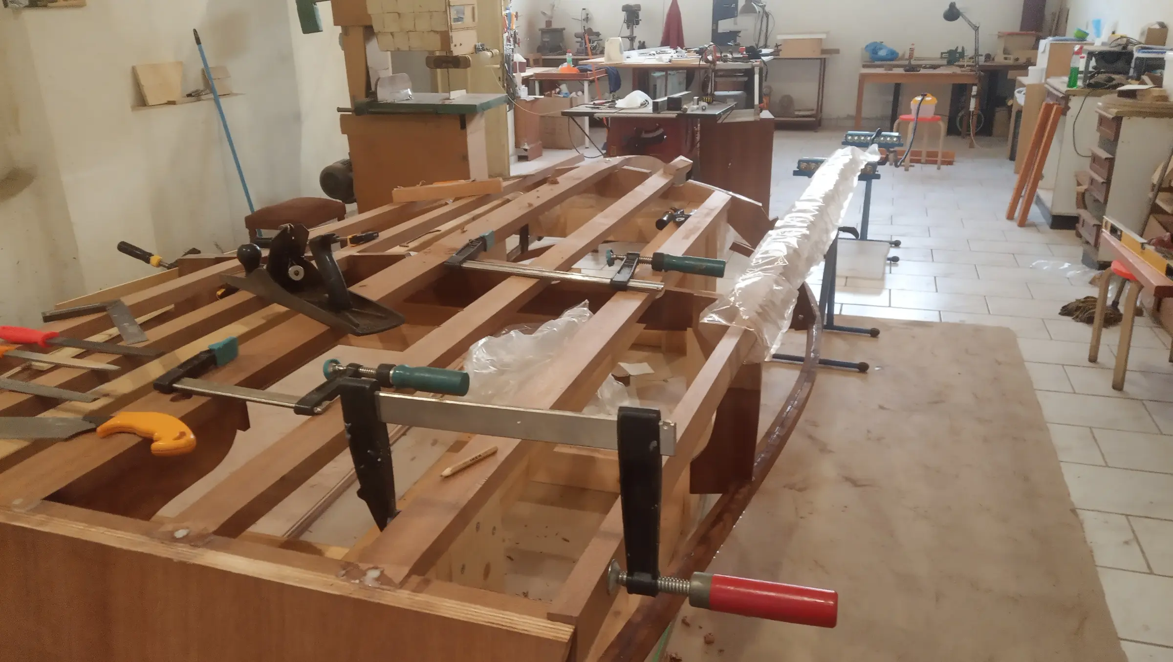
Some photographs of the glue-up with the clamps.

The next job was gluing the last timbers of the boat's framework, the chines. I had overestimated what my steamer could do and had intended to glue a single 2.5 cm thick piece on each side. After an hour the timber bent fairly easily, but it also had to twist along its length at the same time, a long way, and in opposite directions at different points. I could not do it.

In the end I cut the pieces in half on the bandsaw. That left roughly two pieces of 1.1 cm of clean timber. If anywhere needs to be thicker, a third piece will be glued on.

I found that the gluing surface, done the way the plans show it, would be very small indeed. It makes no sense to glue nothing but end grain onto the keel at an angle. So I decided to make a backing piece like the one the sheer timbers land on. I took a rough measurement of the angle the pieces arrive at and copied it onto the backing piece. Thirty-six degrees on each side. Also 12 degrees off vertical, which turned out to be wrong. It needed more, read on.

The points at the transom and at the first frame, which did not need much bending, were glued first. Then they were heated with the steamer and glued at the second frame. I chose to glue the forward point last, so I could see where the backing piece would need to go. One problem that can come up is these timbers sitting lower than the surface formed by the plywood that joins the sheer timber to the keel. If that happens it will spoil the shape of the boat forward (the V). The higher up it goes (with the boat upside down) the further the timber stands off the surface, but the harder it gets, since its natural tendency is to go downwards (it has to be bent with heat). The plans do not say where they should be fixed. They say it does not particularly matter.

After the final bend I found the right spot to glue the backing piece. The timber was cut at the right point ready for gluing, and the backing piece was glued on.

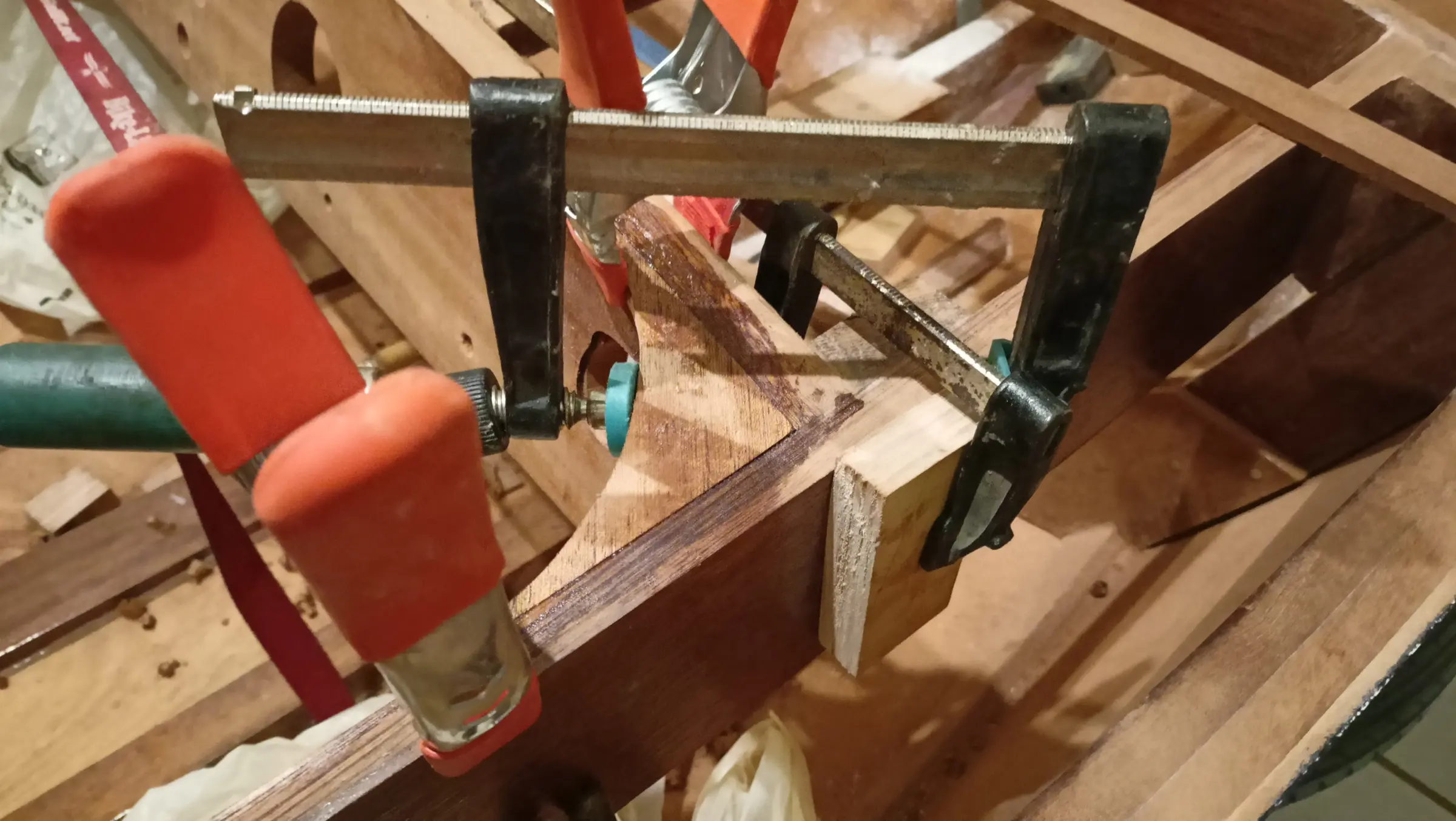
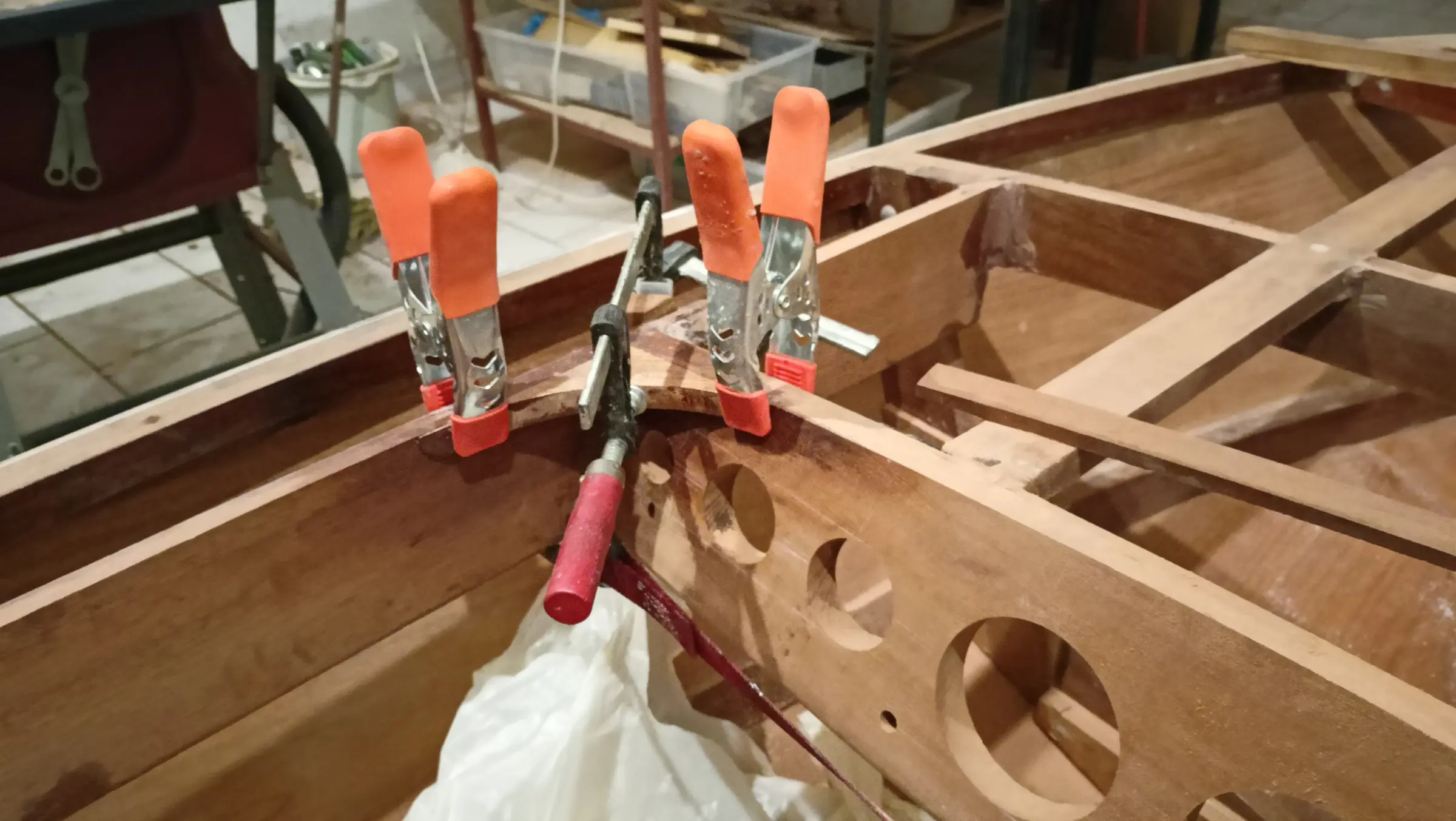
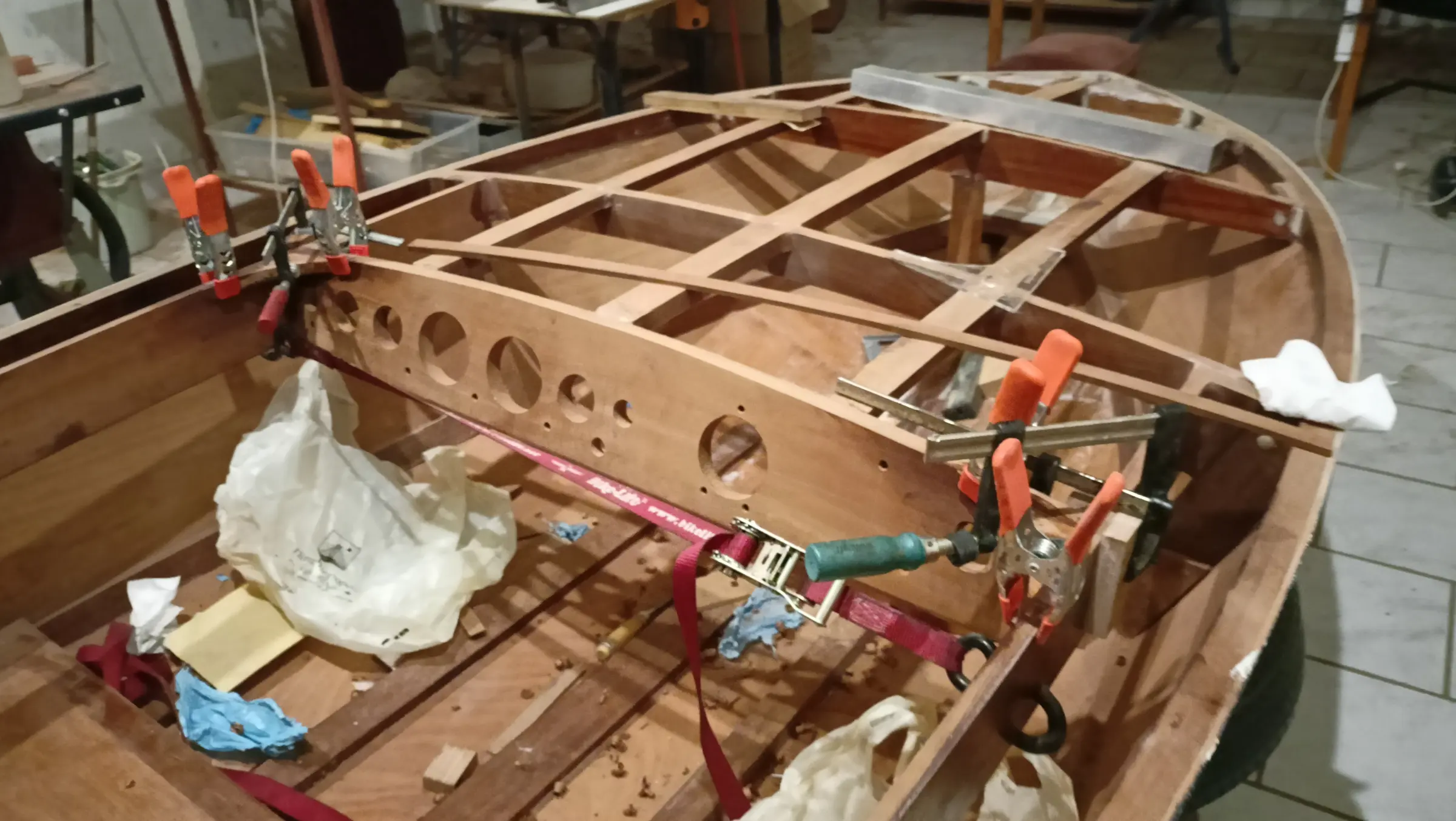
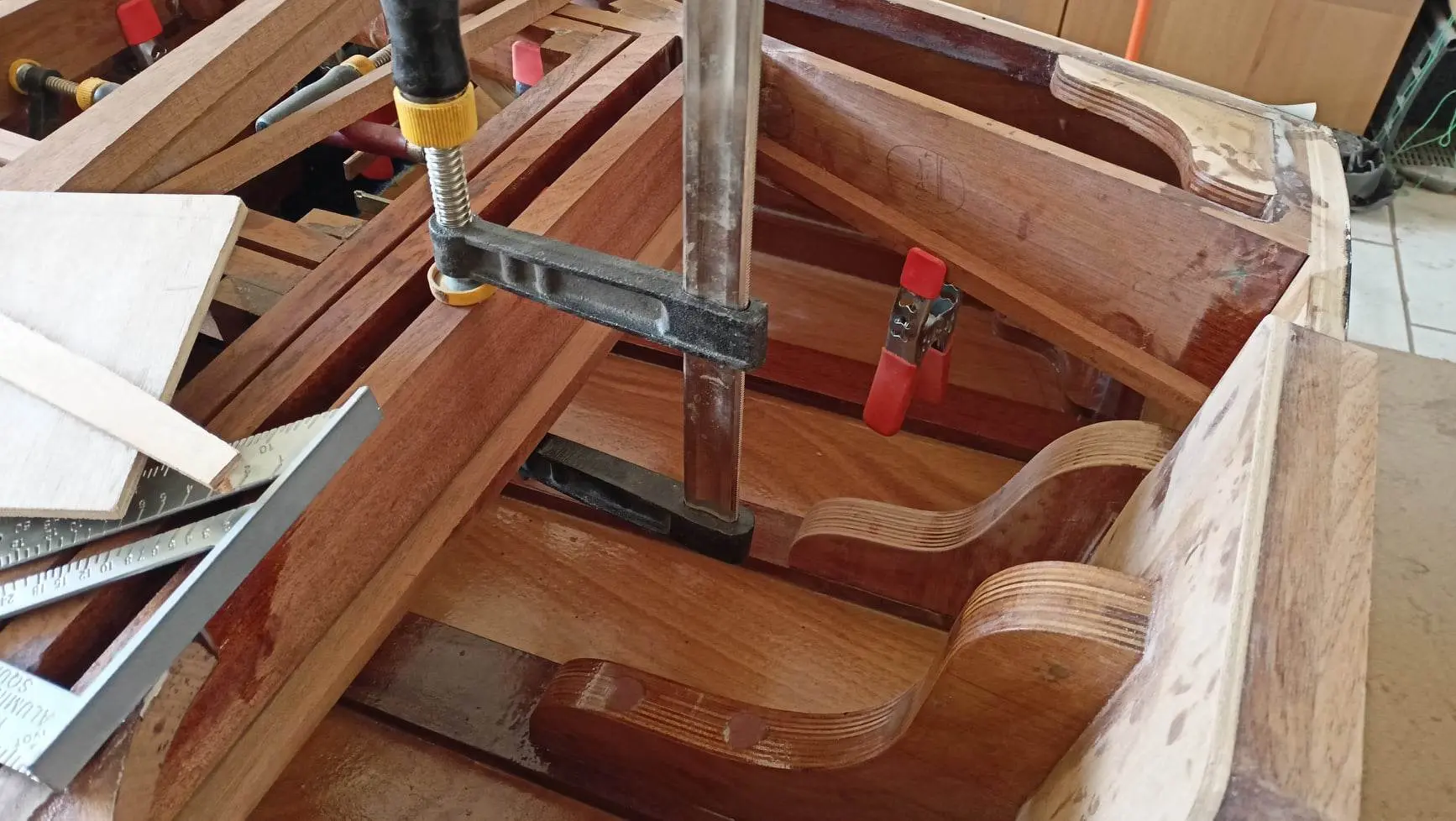
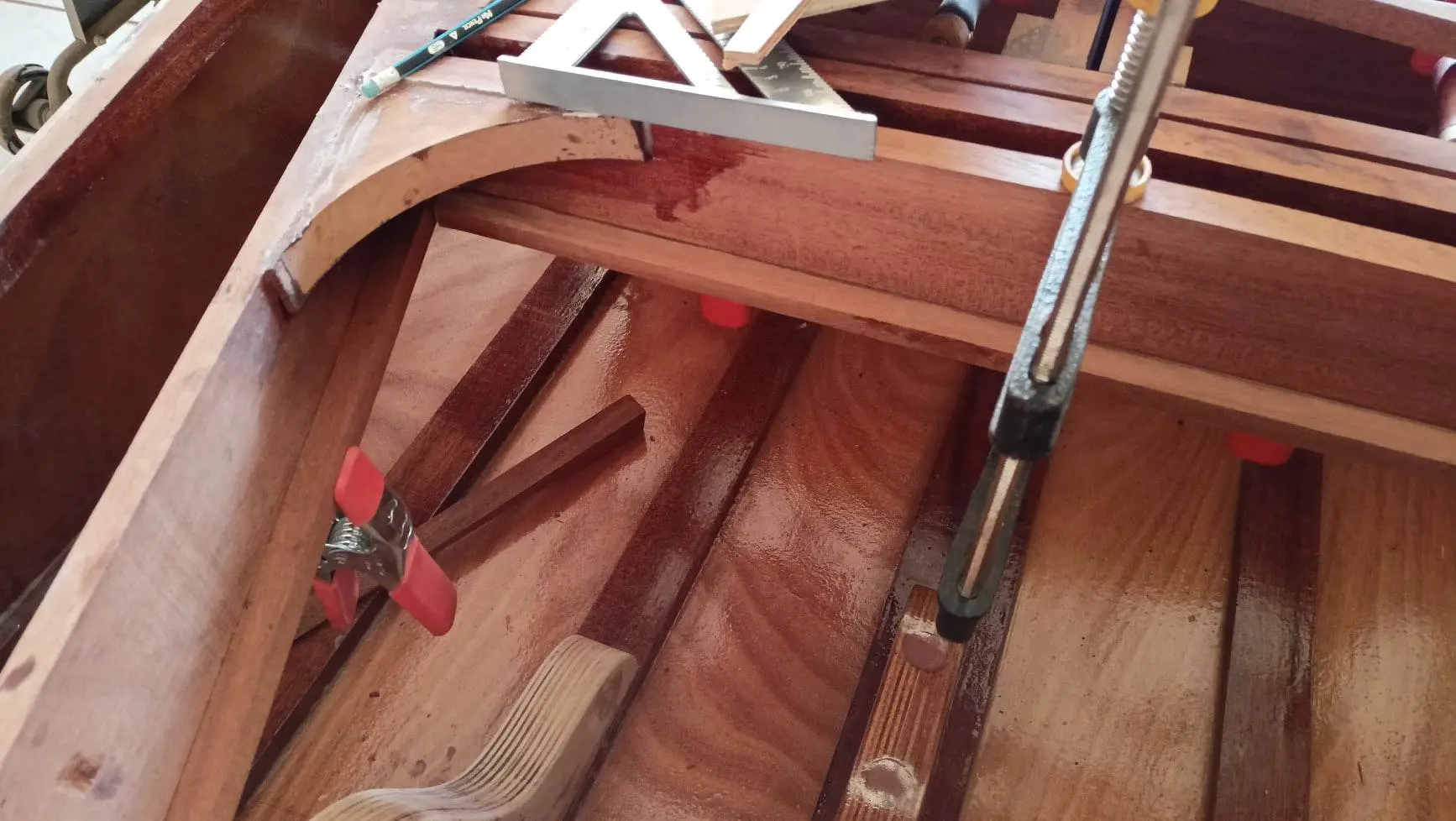
Then came the glue-up, with a lot of clamps.

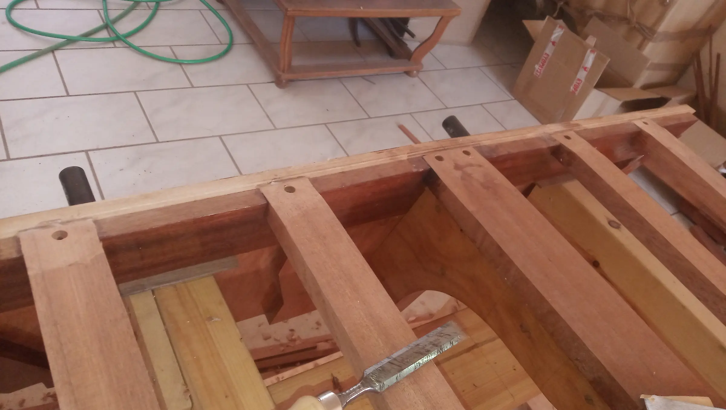
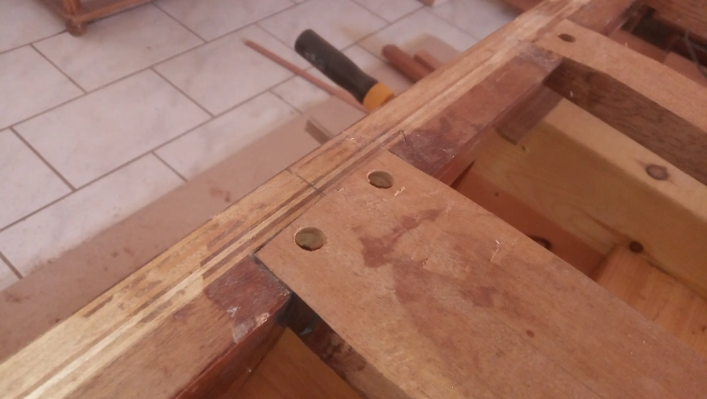
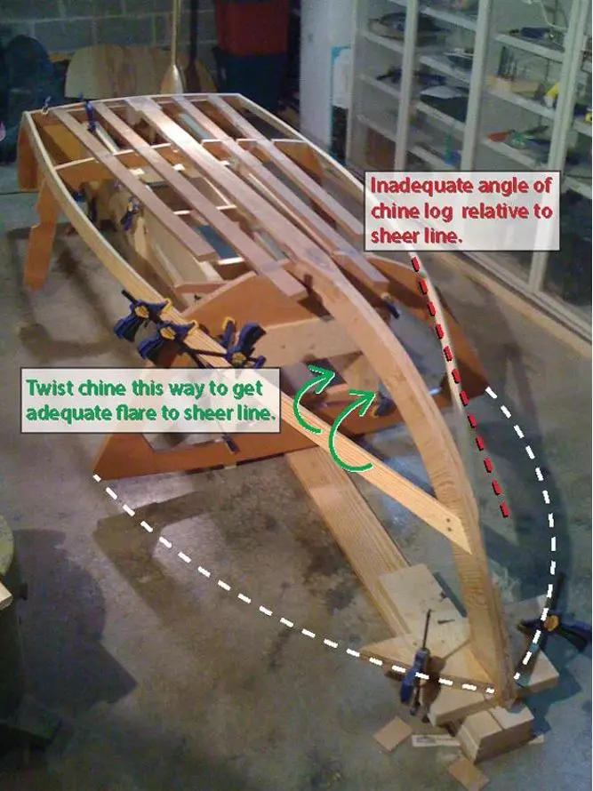
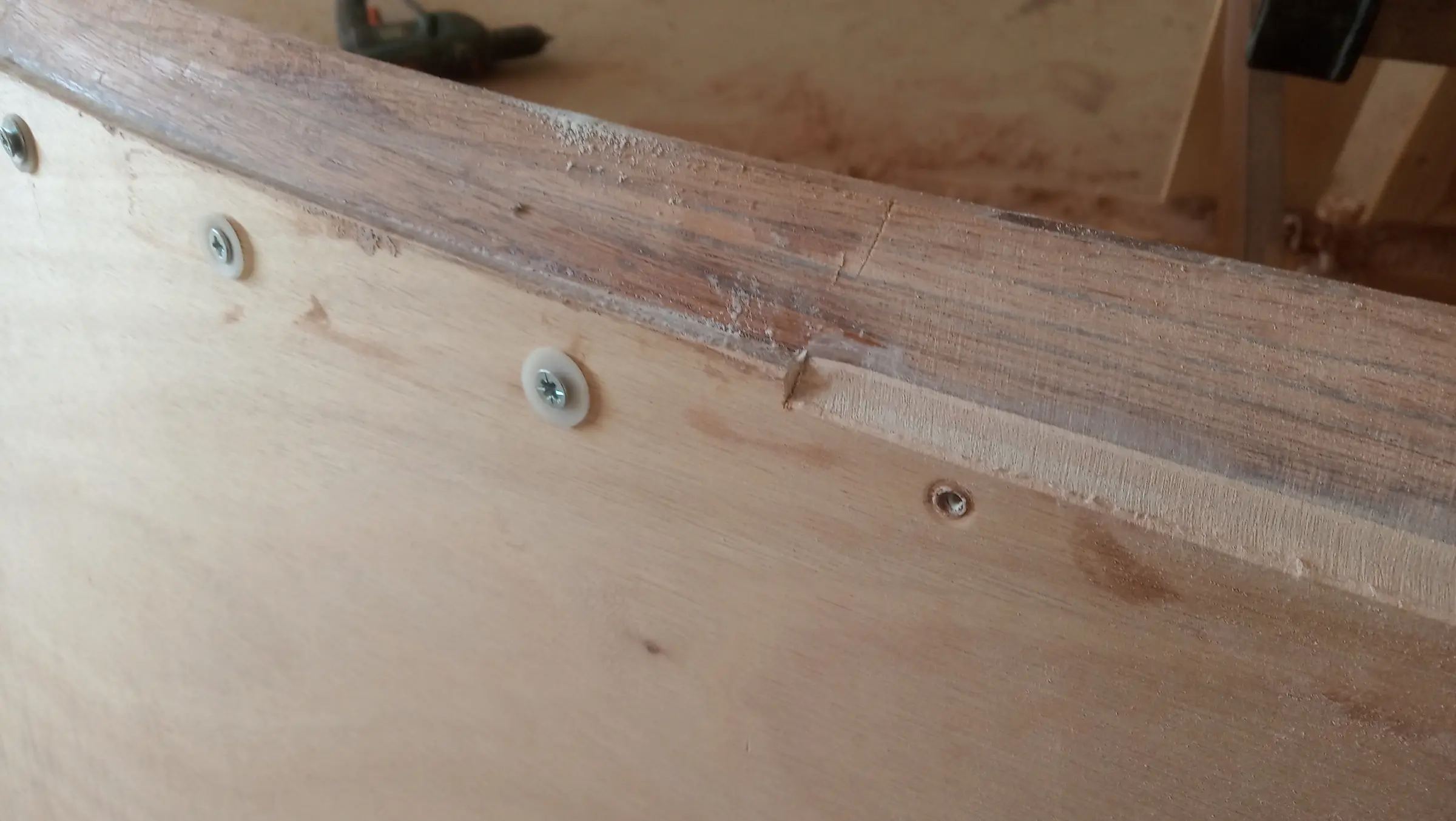
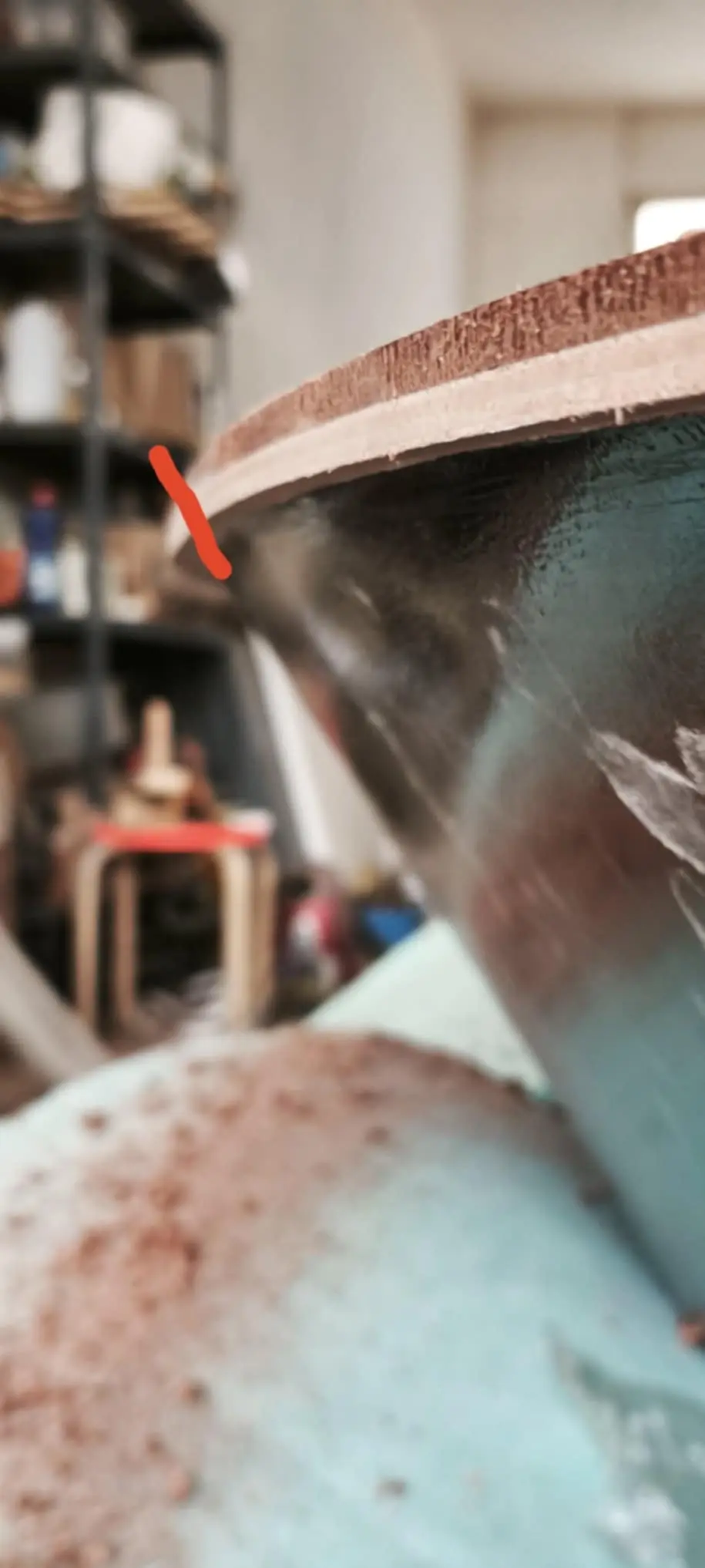
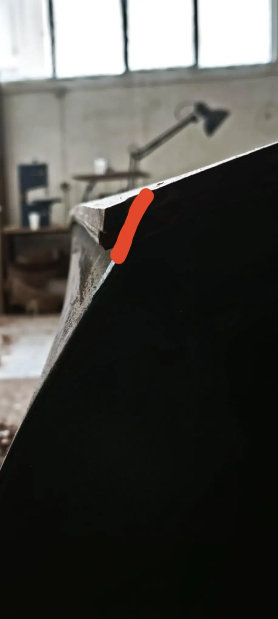
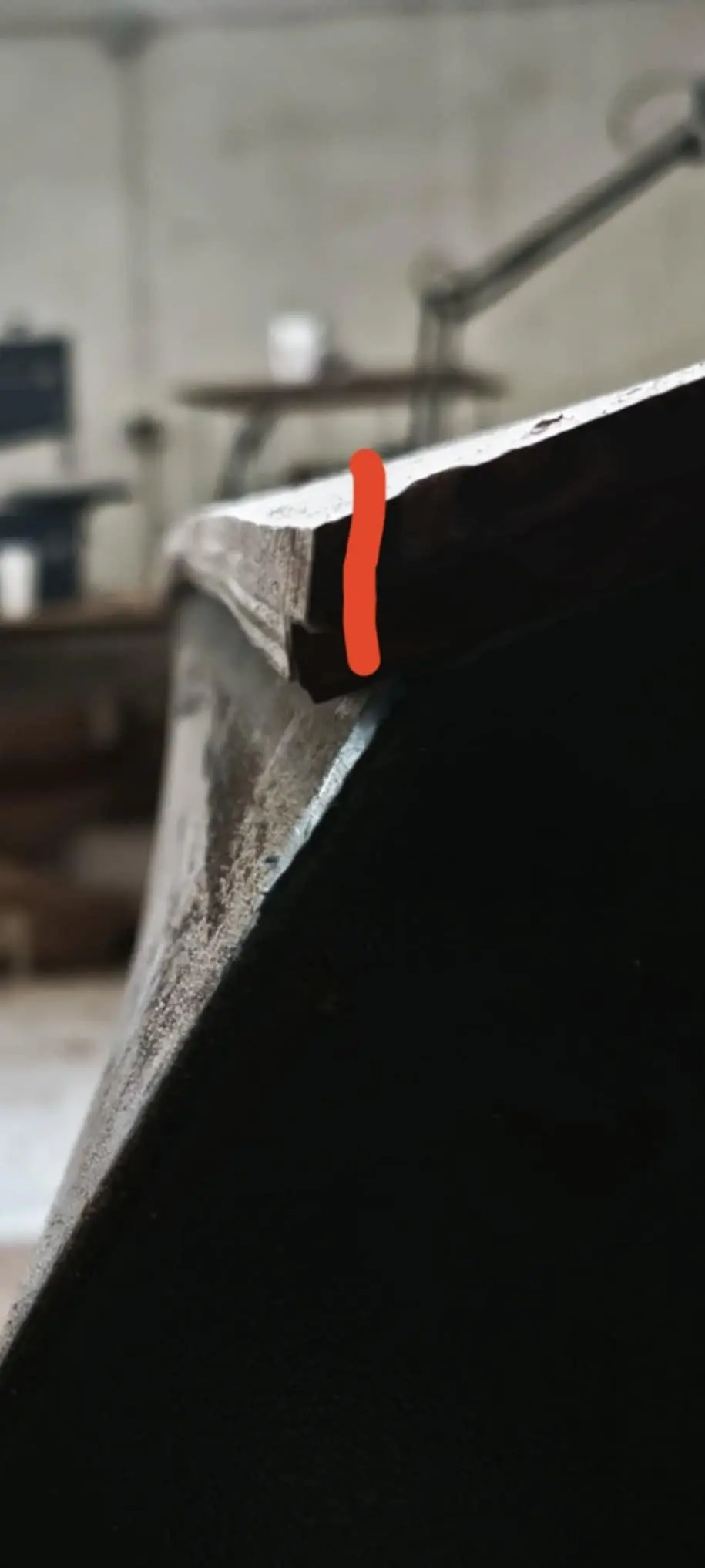
Once both pieces were glued I found their bevel was wrong. I found the photograph below from another build to make the problem clear. The bevel shown by the red line is the problem. The red line should come outside the white one, so that the timber can be cut back to a bevel the plywood can be glued to.

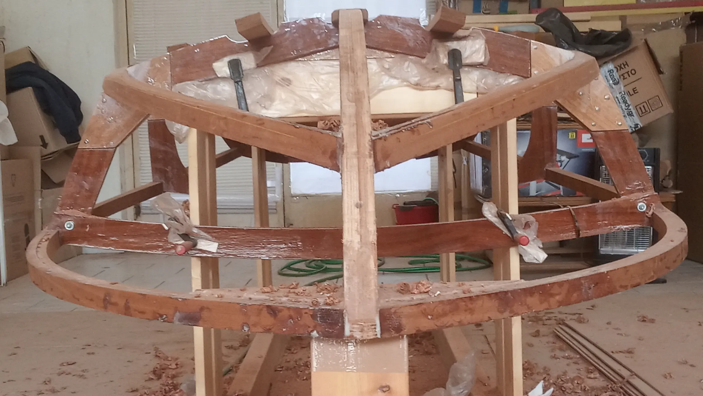
To get that bevel I would either have to unglue and reglue the timbers, which is very difficult with epoxy, or glue new pieces on top and cut a new bevel. This is a mistake which, as I found out, has been made on almost every build of this particular boat. The photograph below shows the framework in its final state.

Video: https://www.youtube-nocookie.com/embed/1WLVIWMFxnM

Video: https://www.youtube-nocookie.com/embed/dBZHRBLfTlc

Video: https://www.youtube-nocookie.com/embed/Jtr7T_cbn2g

Video: https://www.youtube-nocookie.com/embed/yUqkchpmW34


30 h

Fairing the framework

Fairing the framework is essential work, so as to create the surfaces the hull plywood will be glued to. The process starts with fairing at the transom and the frames.

Then, using a straightedge, I mark the curve above which material will have to come off.

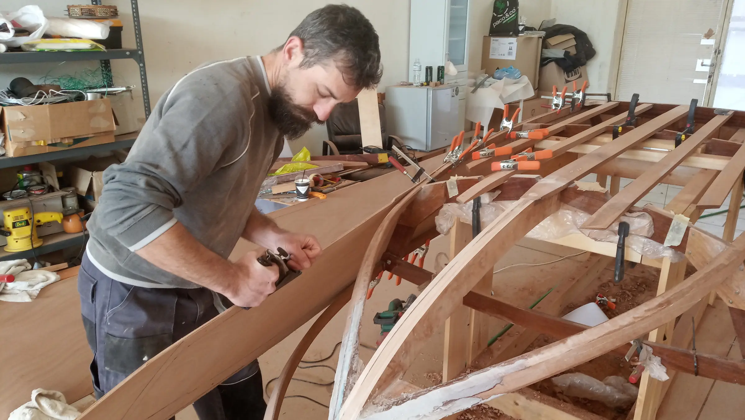
The whole job is done with a hand plane, a rasp and sandpaper, and it is difficult, tiring and above all nerve-racking. Nerve-racking because in some places a lot of material comes off. There is not much wood left, and depending on how it turns out it may need reinforcing from the inside.

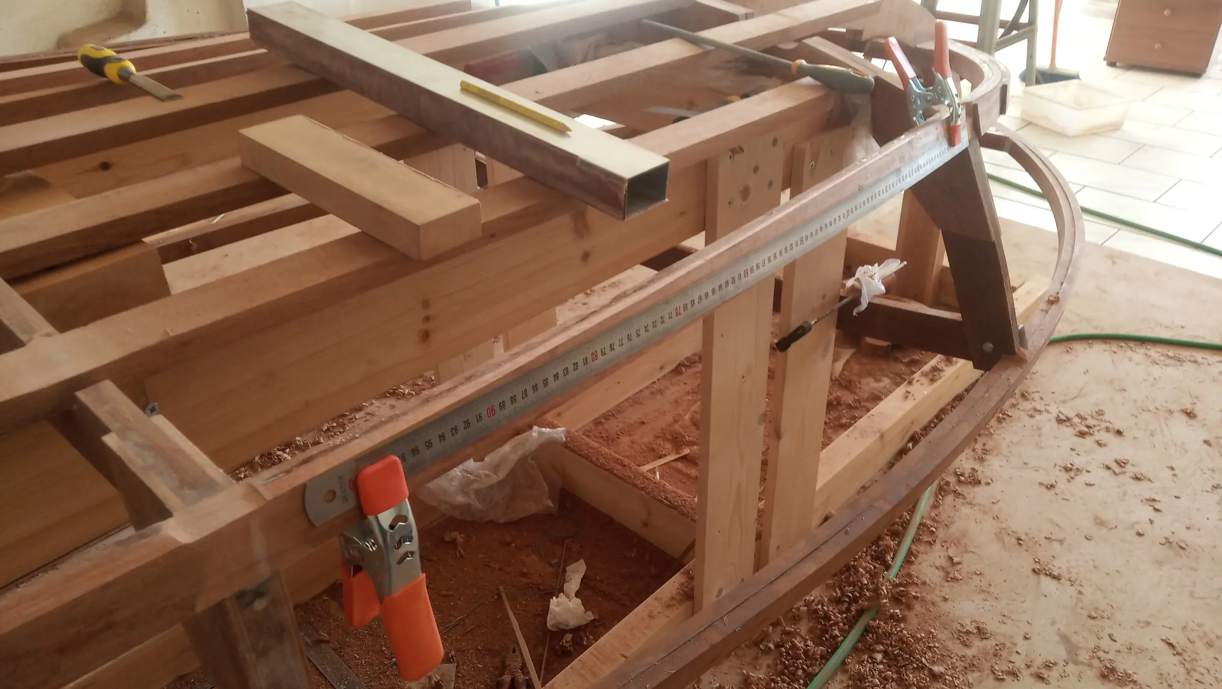
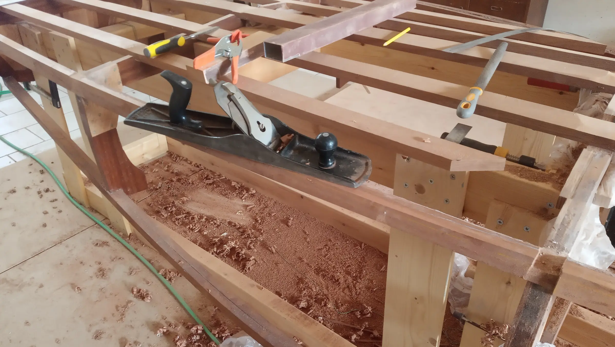
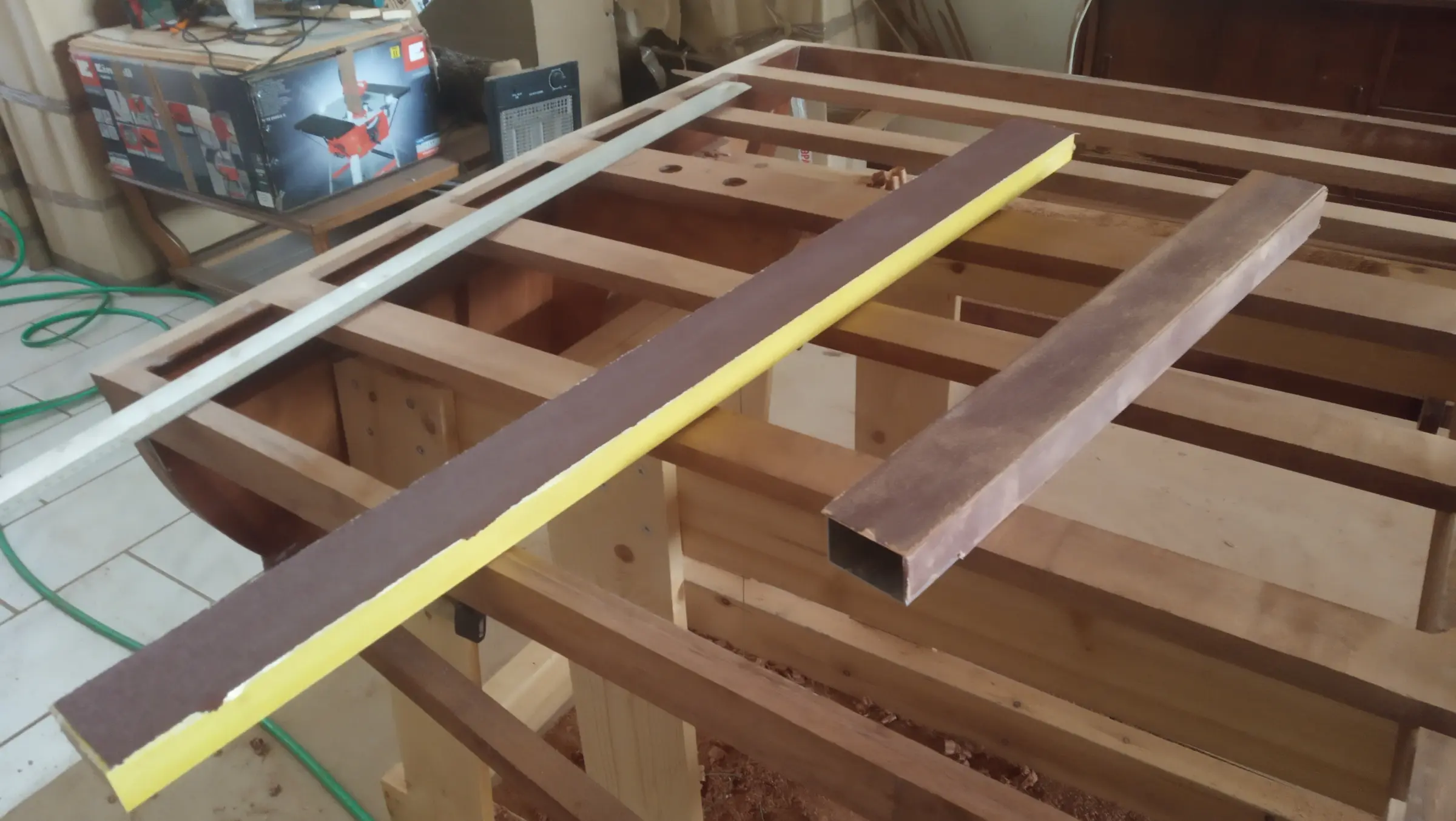
Once I had finished the frames I carried on with the top of the boat as it sits on the base, which is to say the bottom of the boat. The aft section is the easiest part, as it is made up of two straight lines. The work starts with the hand plane to take off the bulk, and then with coarse sandpaper which I have glued to a large flat board, sanding all the timbers on one side together.

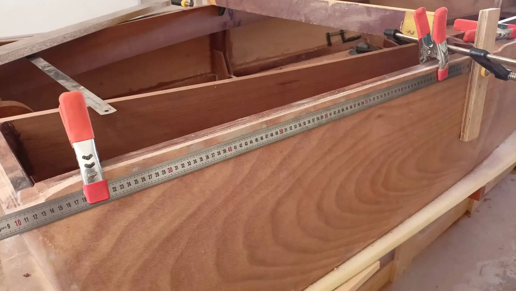
On to the sides of the aft section. Here the process is a little different, because we do not have straight lines but curves, and curves that change as you move forward. The timber was taken off little by little, checking with a piece of plywood 30 cm wide.

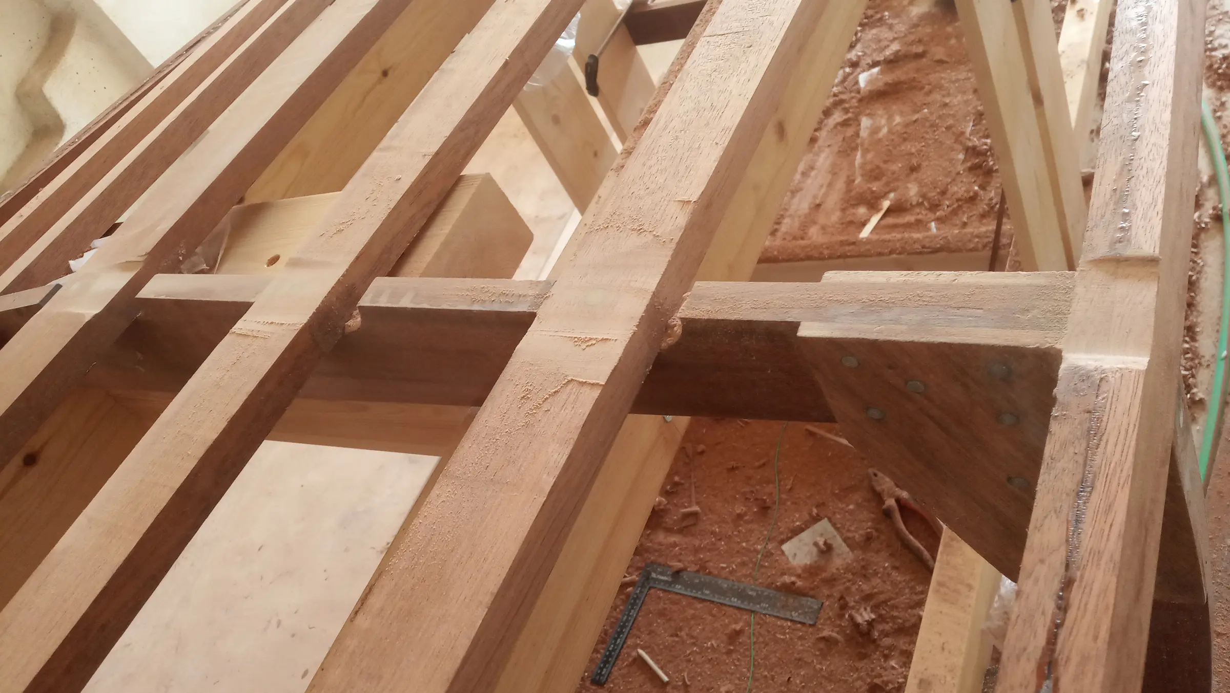
On to the middle section of the boat. Much the same process. Here the bottom timbers that do not terminate at the second frame had to be thinned as well. The process is a little different because at the second frame we do not have straight lines. So from a straight line at the first frame, where I could sand all the timbers together, I ended up with a curve as I moved forward. In fact, so as not to lose too much wood off the two that do not terminate at the frame, I had clamped them down.

The last part to work was the bow, which was also the hardest because of the tight curve.

Here the Rabl method was used.

We divide the keel and the two horizontal timbers of the framework into equal parts according to the length of each. Then with a saw we make cuts at those points, following the straight line. We take off the wood that has been marked, and then the rest, having marked it. The method is explained in the link below.

Once that work was done I fitted the keel carriage bolts. That had to be done at this stage because a fair amount of wood had come off and the holes I had drilled had to be counterbored again.

I also took a little off the bottom timbers where they meet the transom, so that any water getting inside runs to the point where the drain plug holes will be drilled.

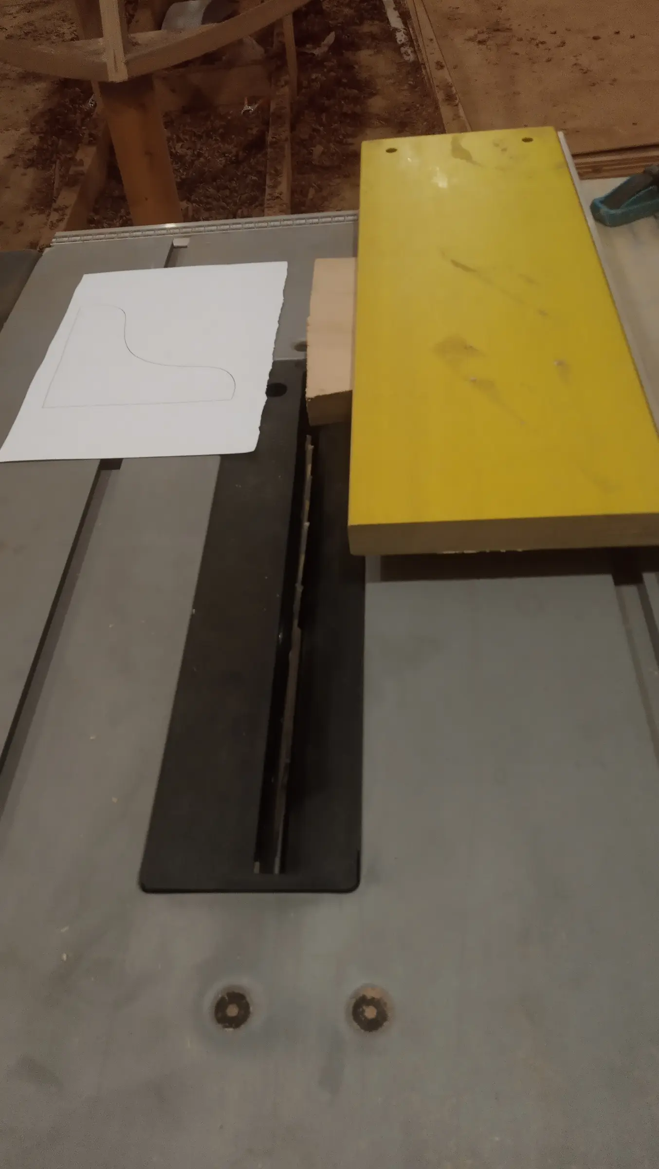
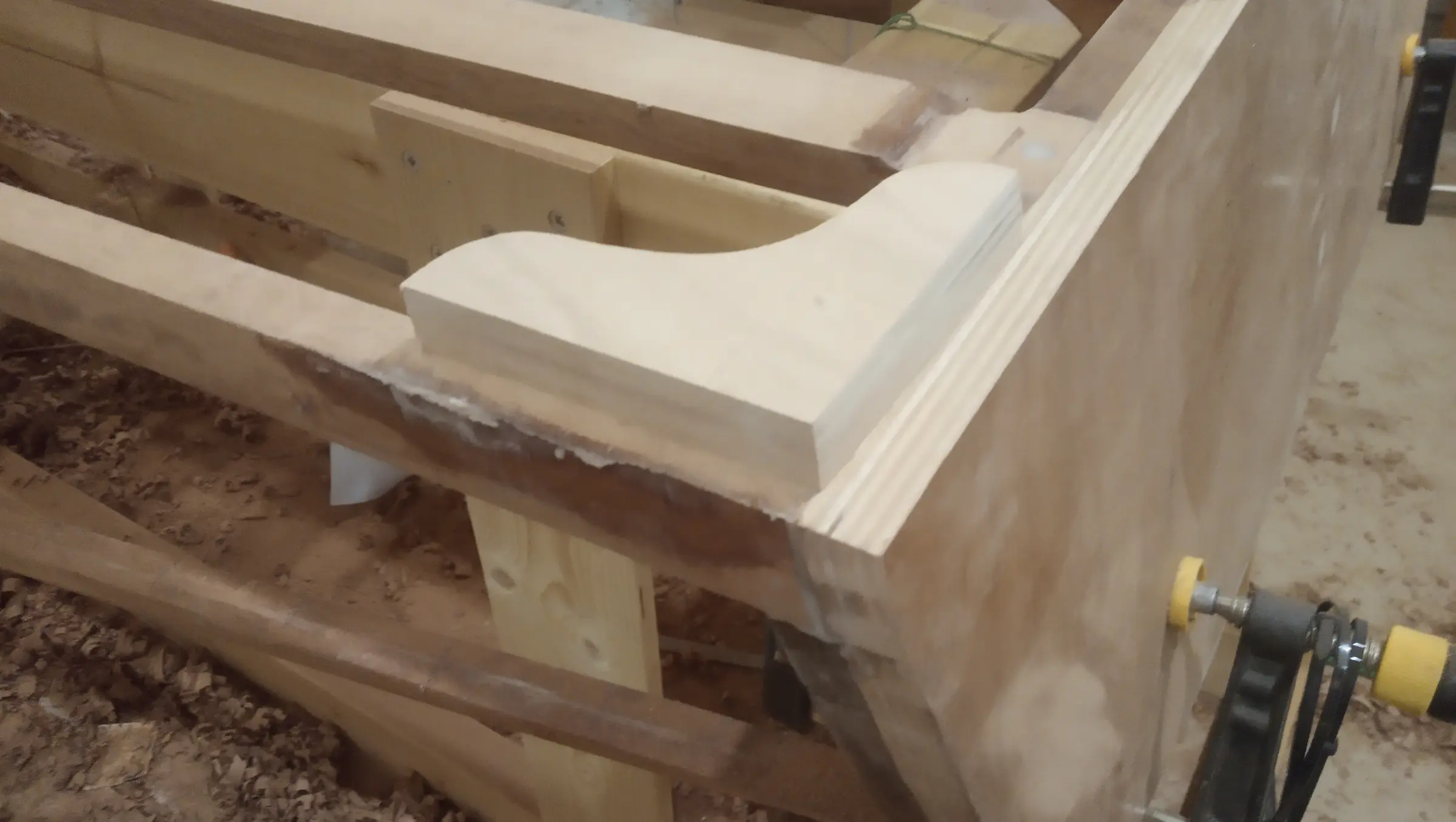
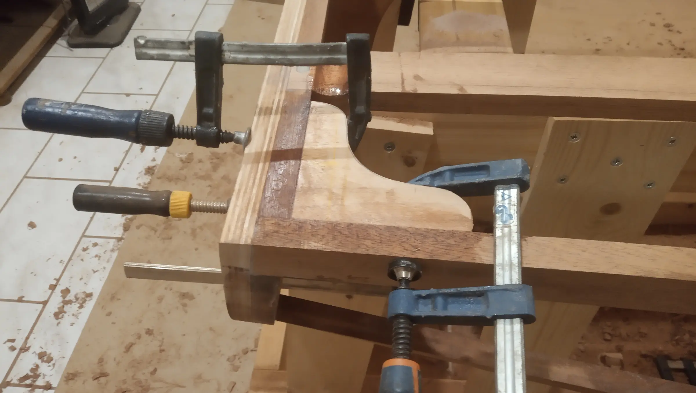
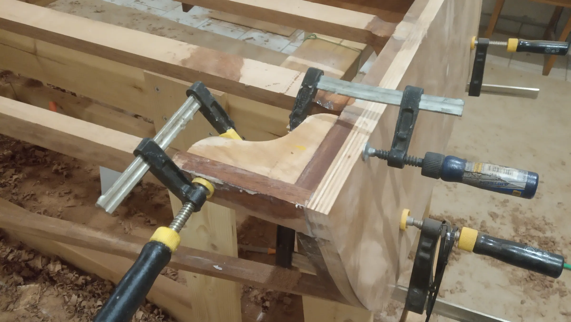
The last job before the hull plywood goes on is reinforcing the transom where it joins the boat's framework. The two plywood gussets were cut and glued, after first cutting the angle on the transom side to match. That was done on the table saw with a fence. I decided to use plywood rather than sapele or sipo, because in one of the two directions the grain would have run the wrong way, with the risk of it breaking if it took a heavy load.


19 h

Planking the hull in plywood

The next job is planking the hull. I am using 6 mm marine okoume plywood from Mourikis, the quality of which is excellent (and, unfortunately, twice the price of other imported stock). Unfortunately it is not made in lengths over 2.5 m, so two sheets have to be joined end to end.

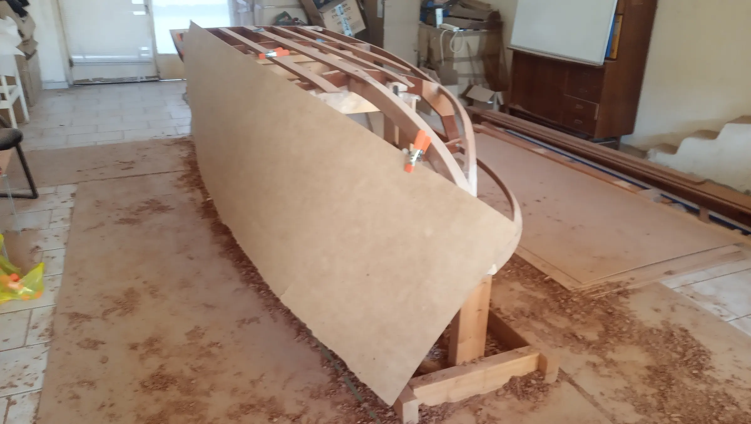
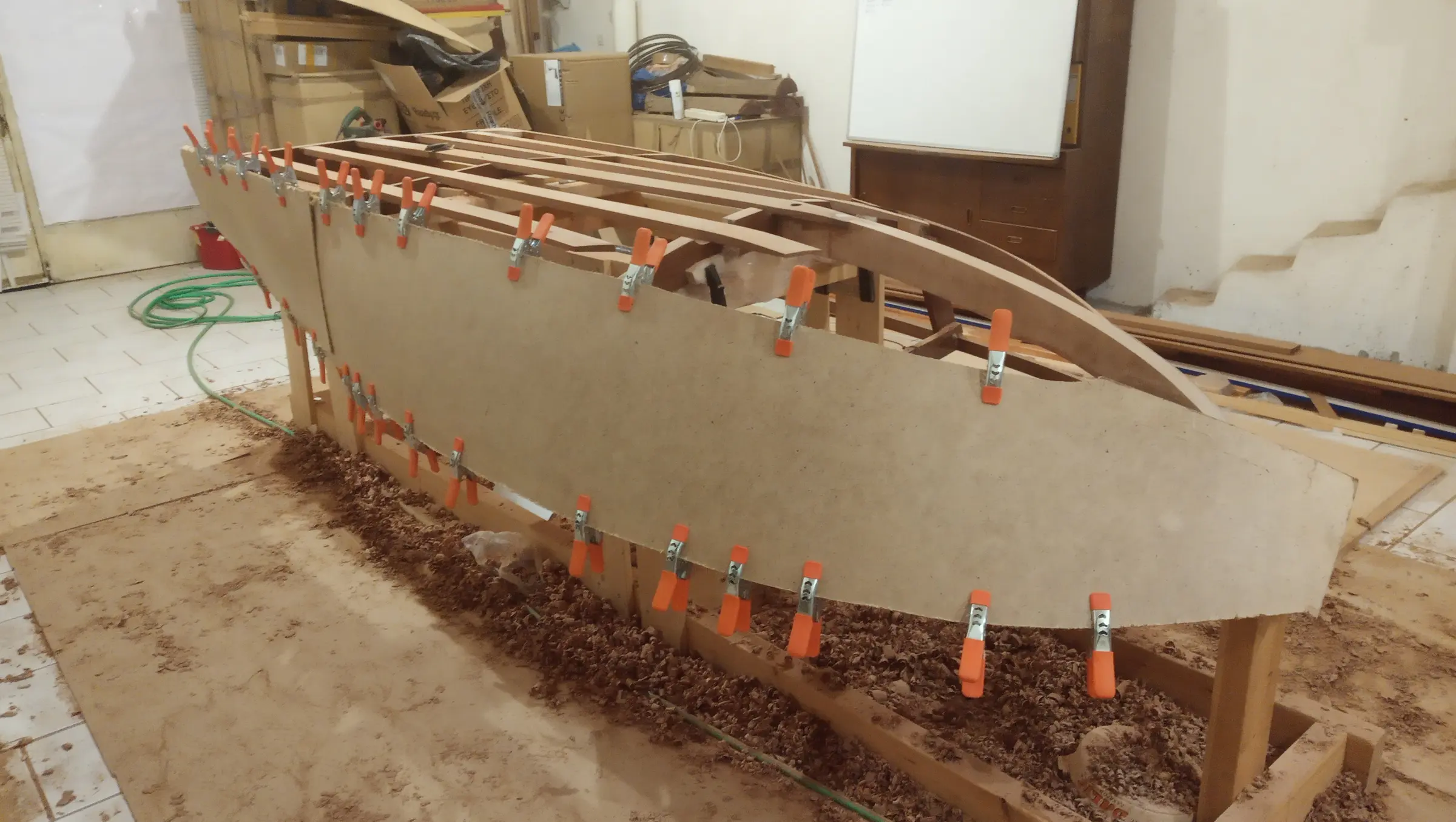
For the hull sides I need a length of about 3.60 m and a width of 48 cm. To work that out I roughly cut a piece of hardboard and clamped it onto the boat's framework.

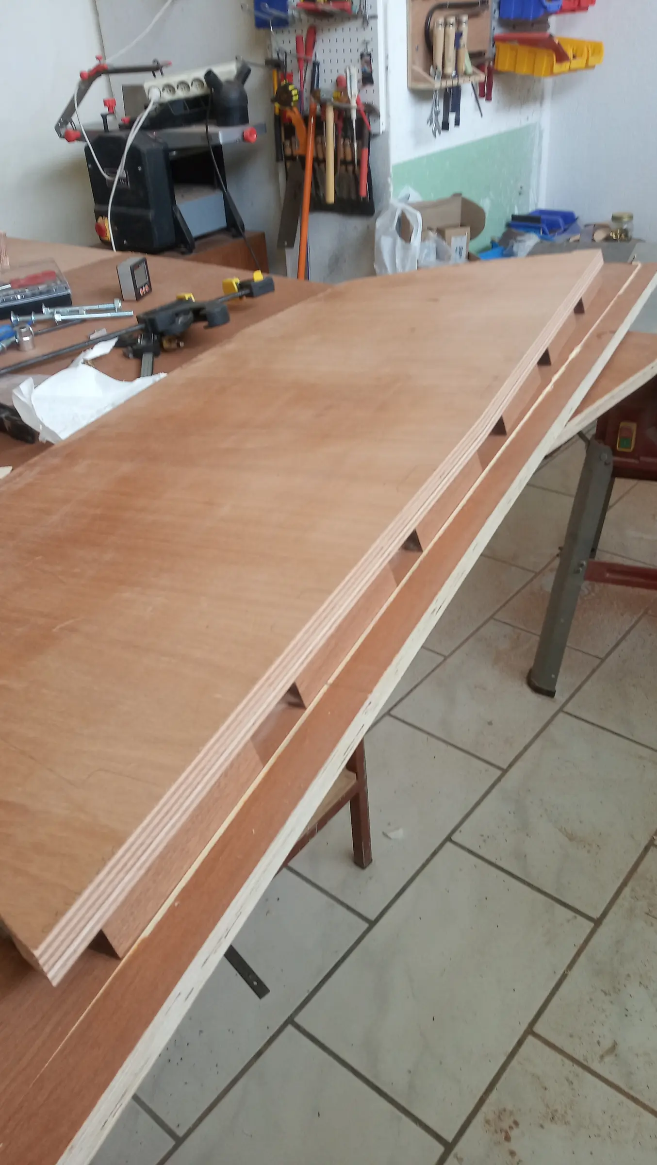
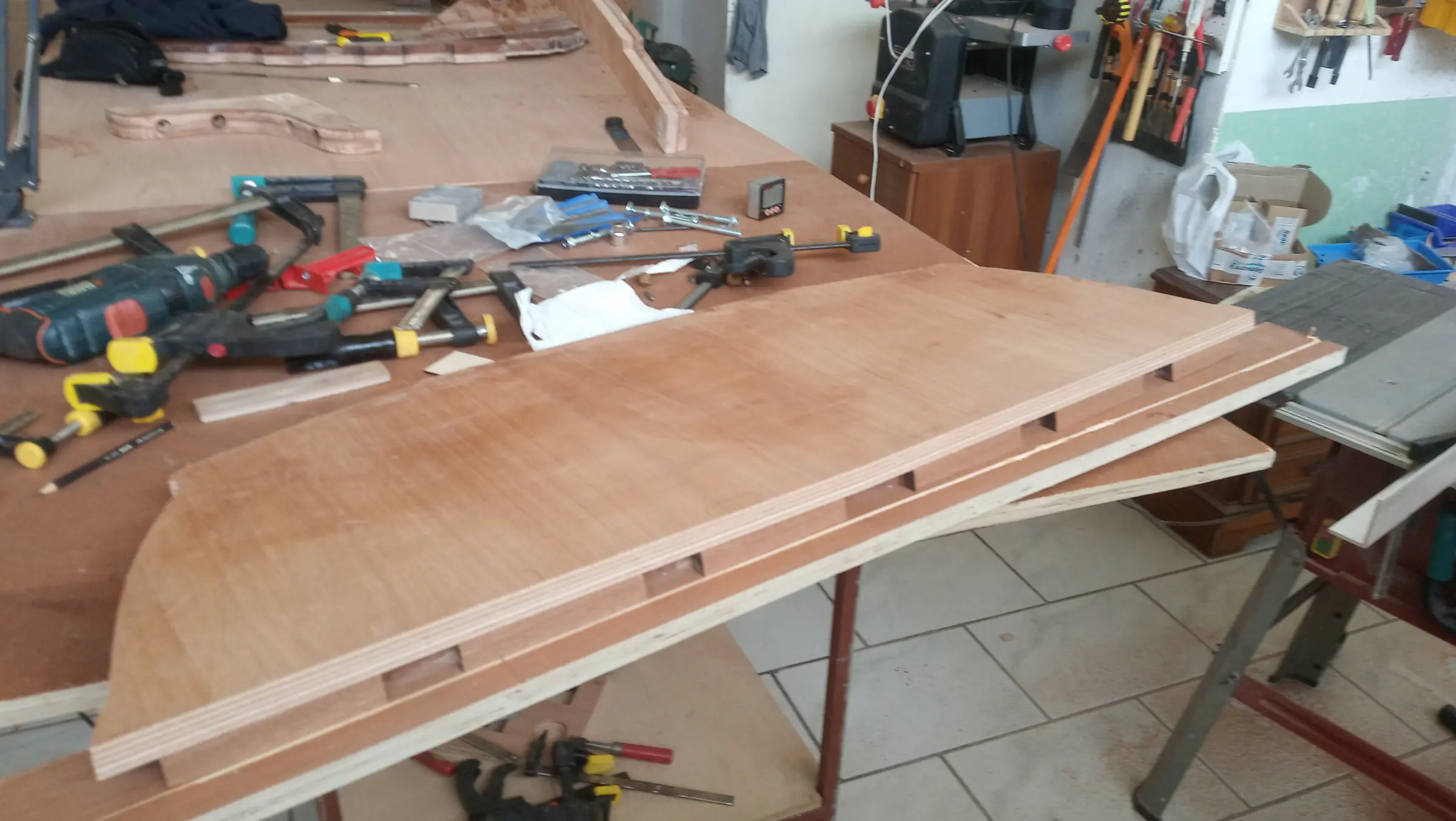
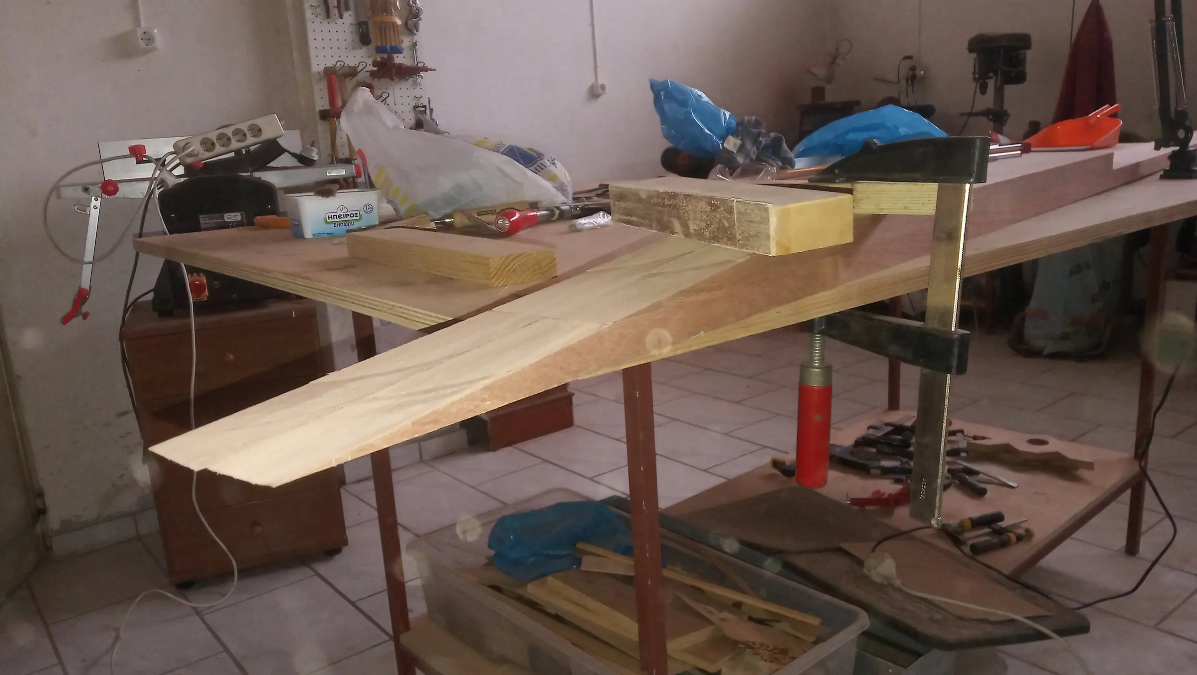
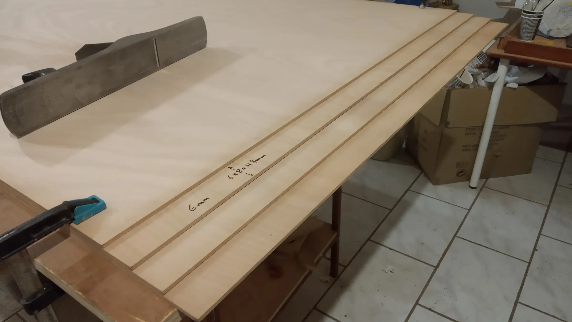
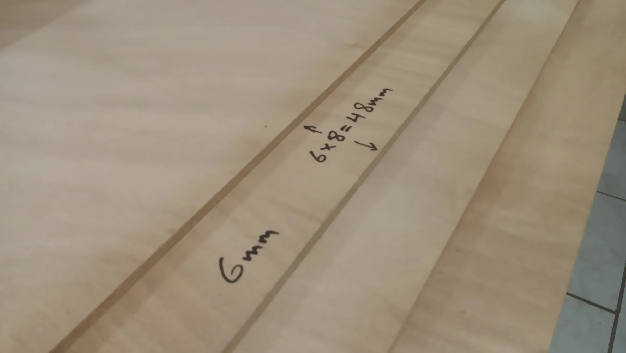
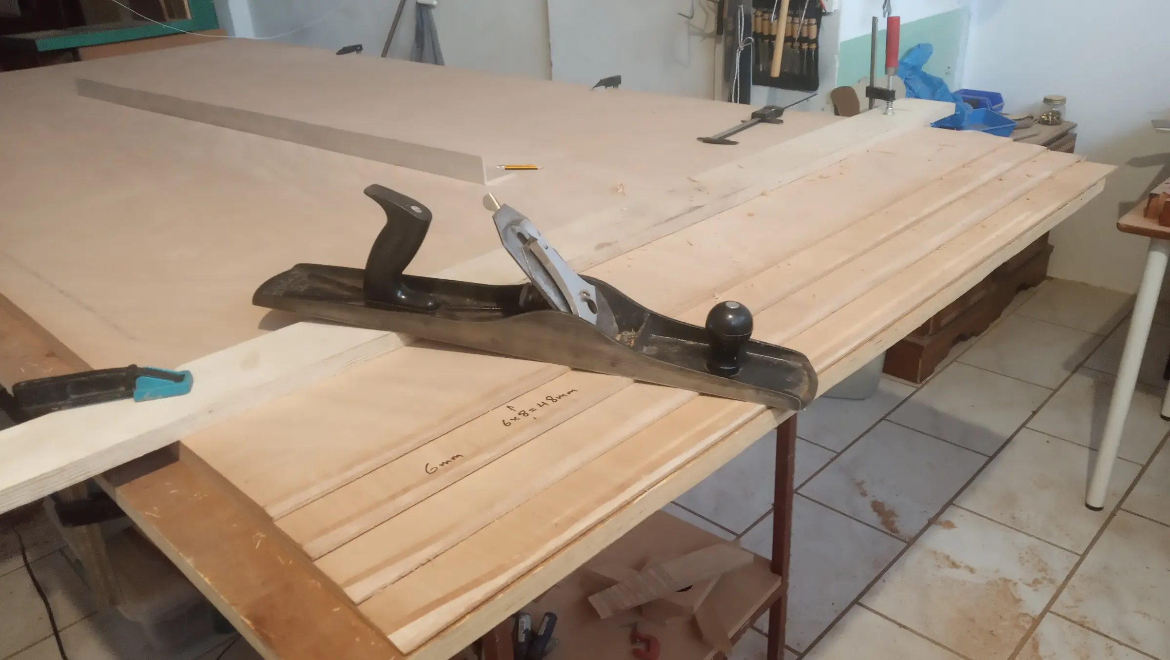
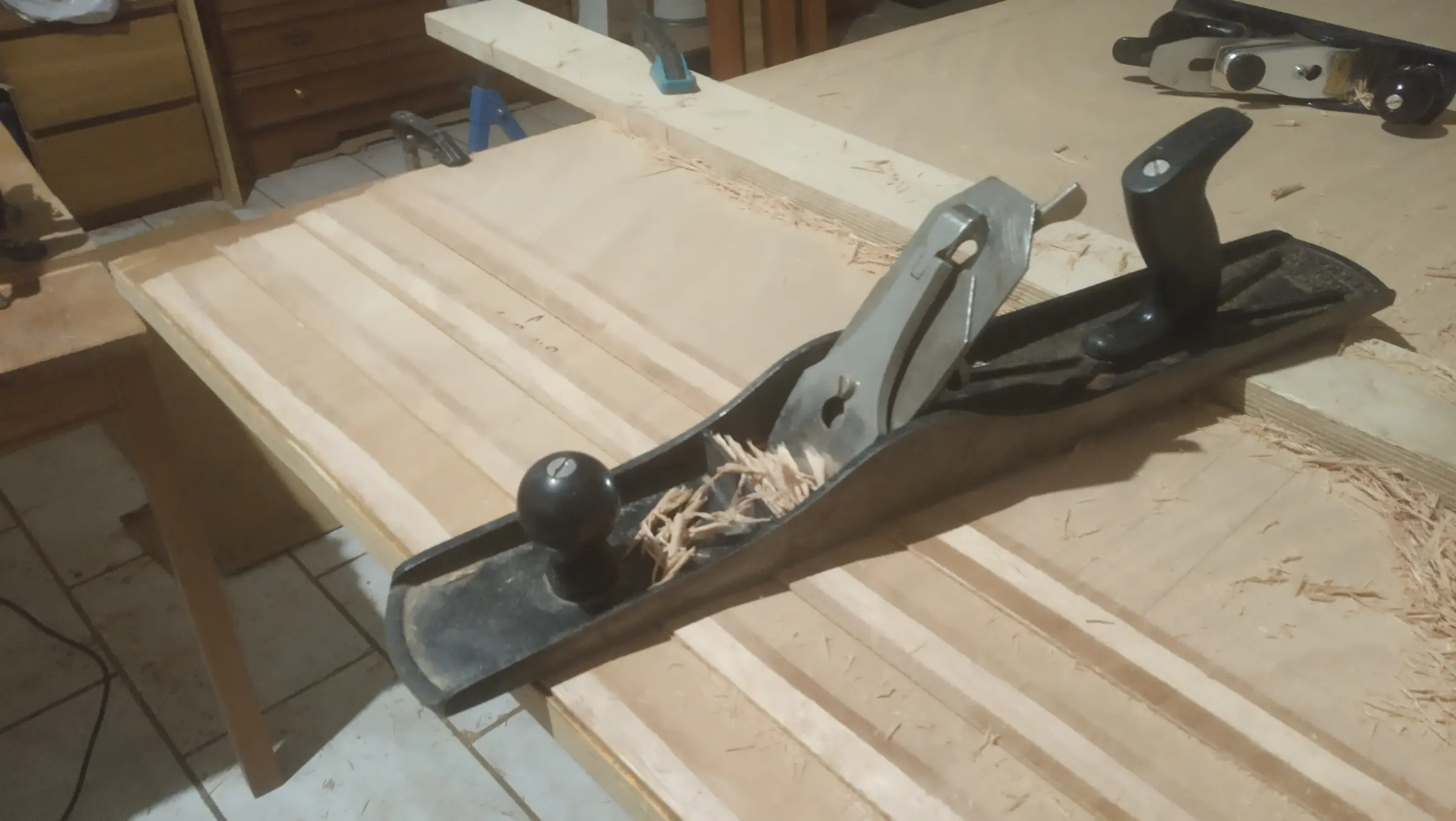
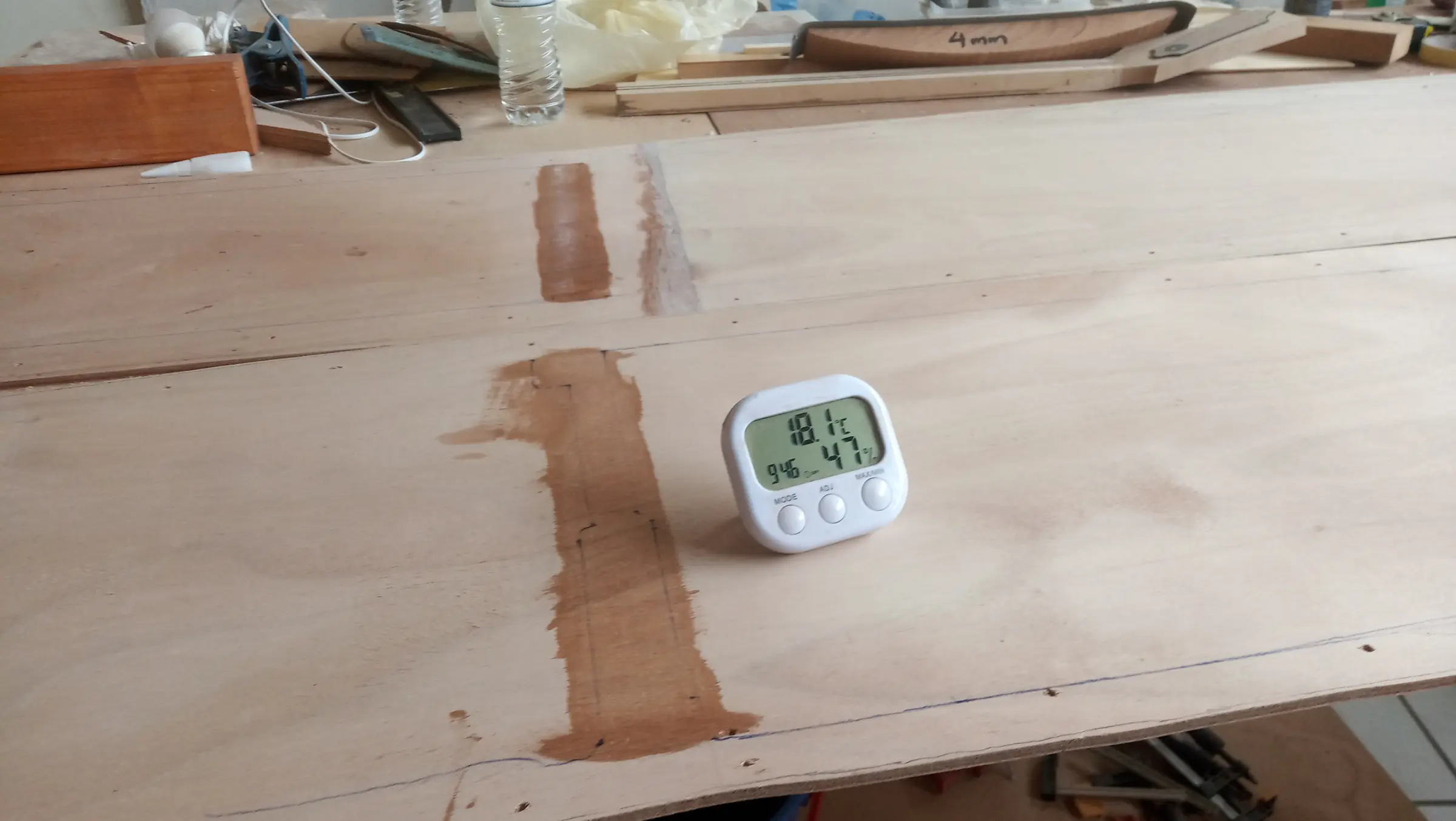
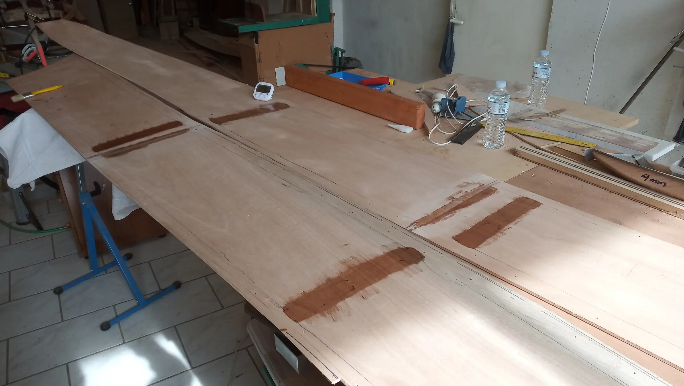
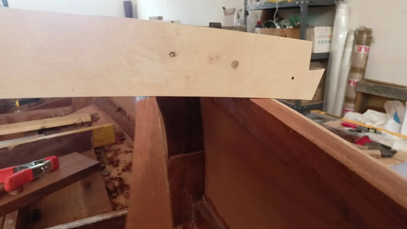
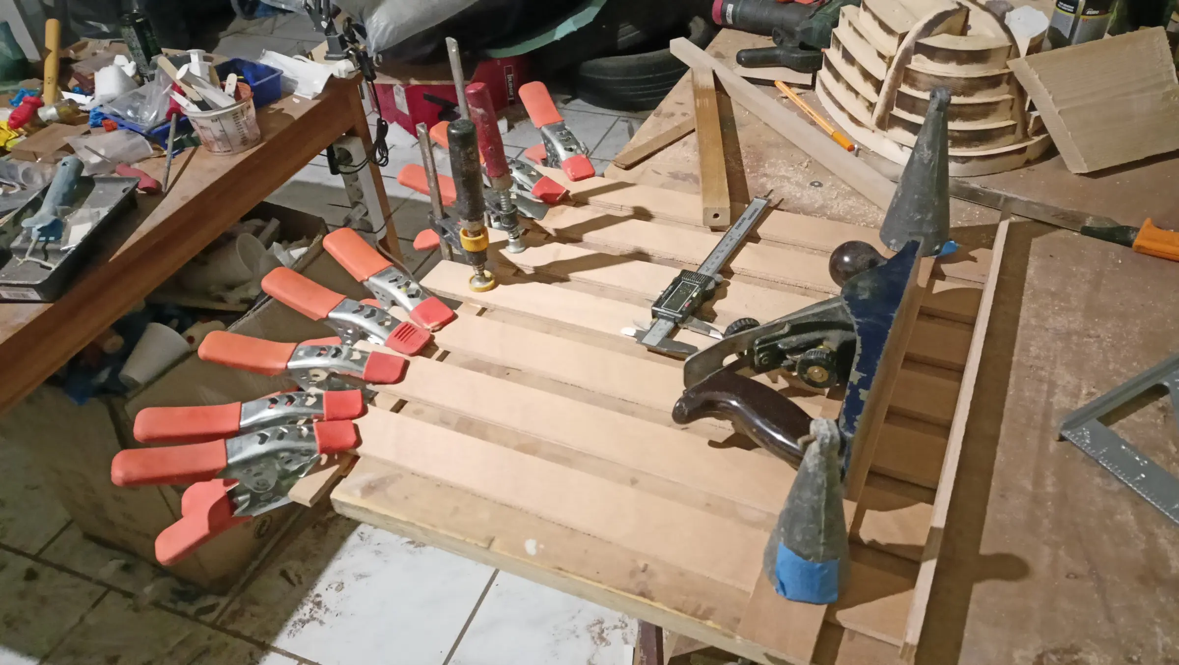
The plywood was joined with a scarf joint. The joint area needs to be about eight times the thickness of the material being glued. So for 6 mm plywood I made the joint 5 cm wide (6 x 8 = 48 mm). I stacked the plywood sheets on top of each other, each one set back 5 cm from the one below, and used a large hand plane to cut the taper. To keep the line straight I also used another piece of 18 mm plywood clamped 15 cm back from the last sheet. The process is shown in the photographs below.

The same was done for the rest of the hull panels, four in total. The joint was made a different way each time, to find the best one.

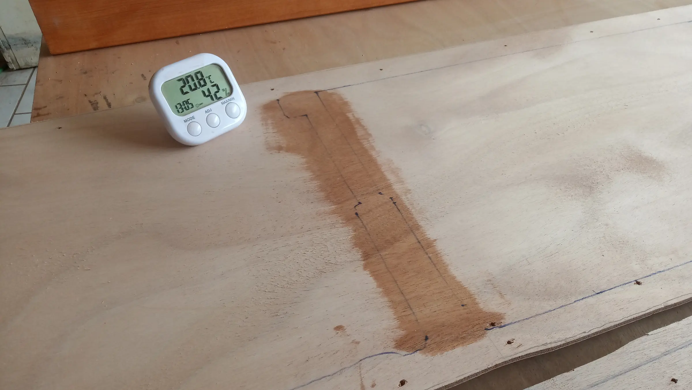
Heating is something that came up in the last days of January and the first of February, as the workshop is very cold, being old. West System resin with the slow hardener (206) has a minimum temperature of 16 degrees Celsius and the workshop got down to 12.5. Two halogen heaters and a fan heater were used for every glue-up.

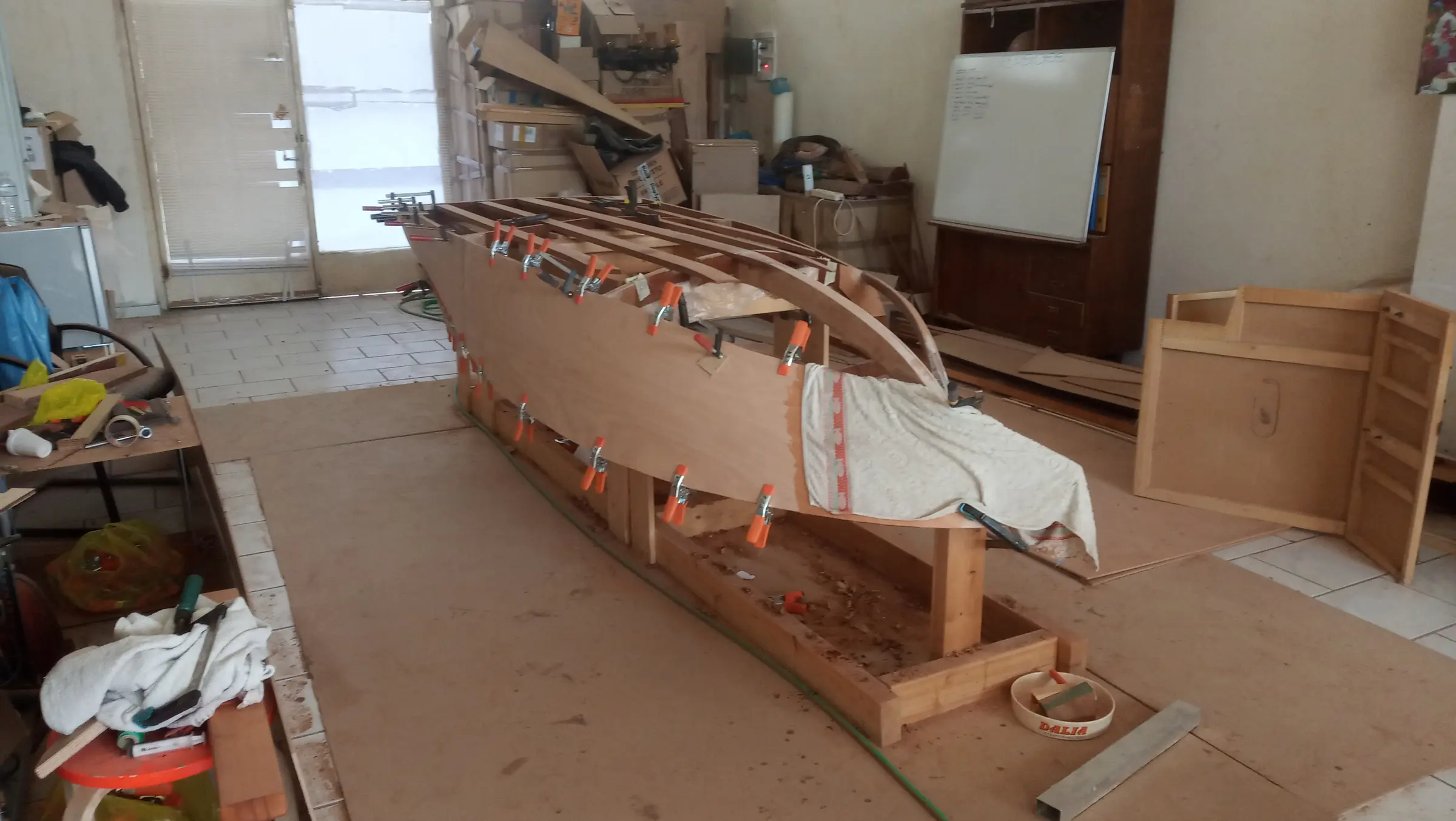
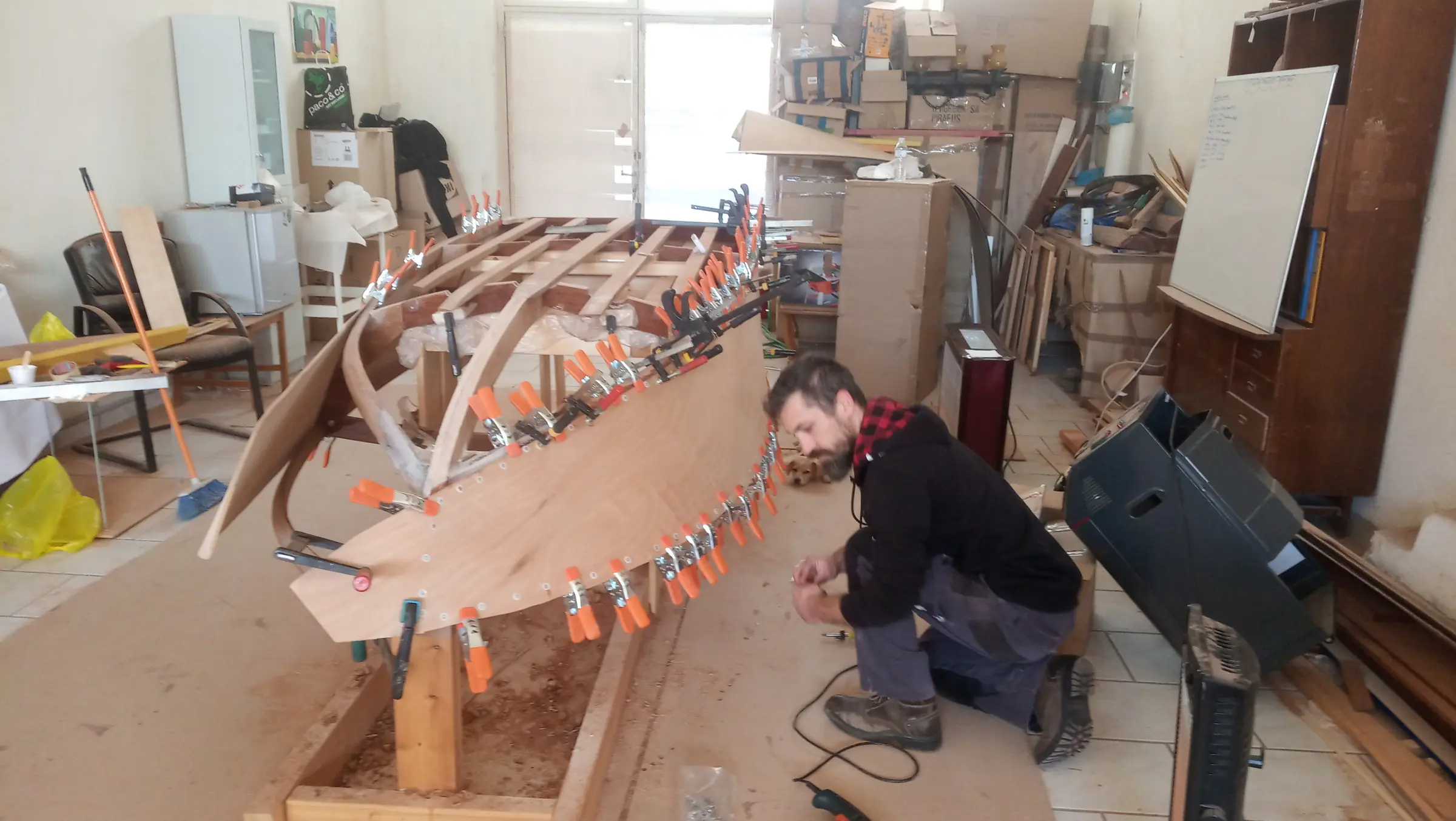
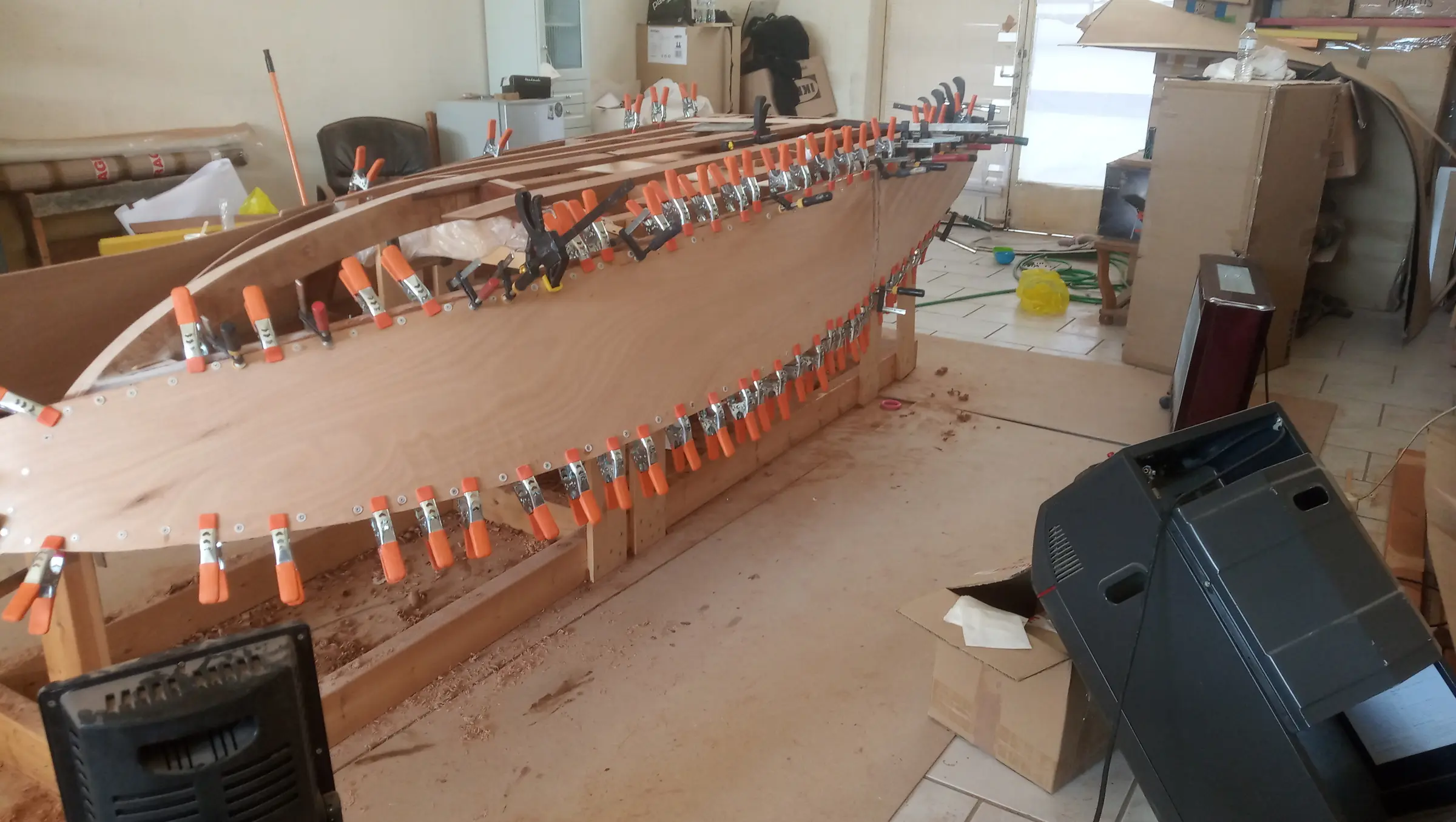
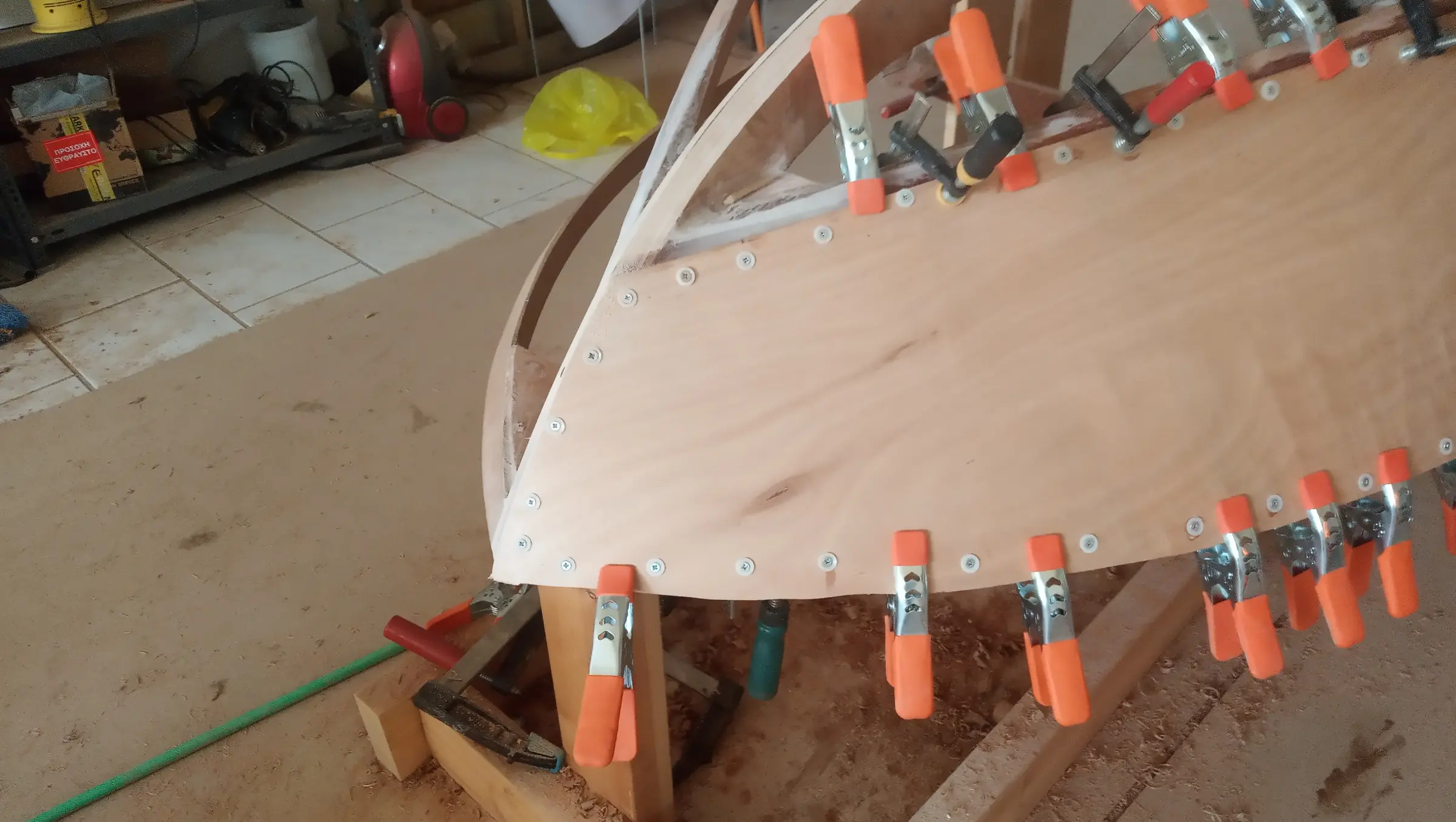
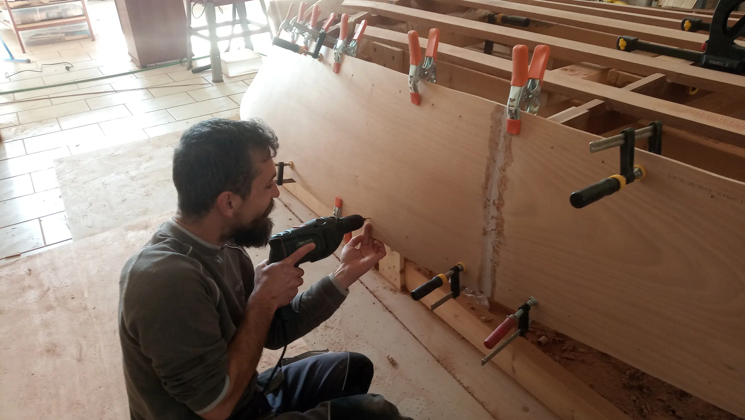
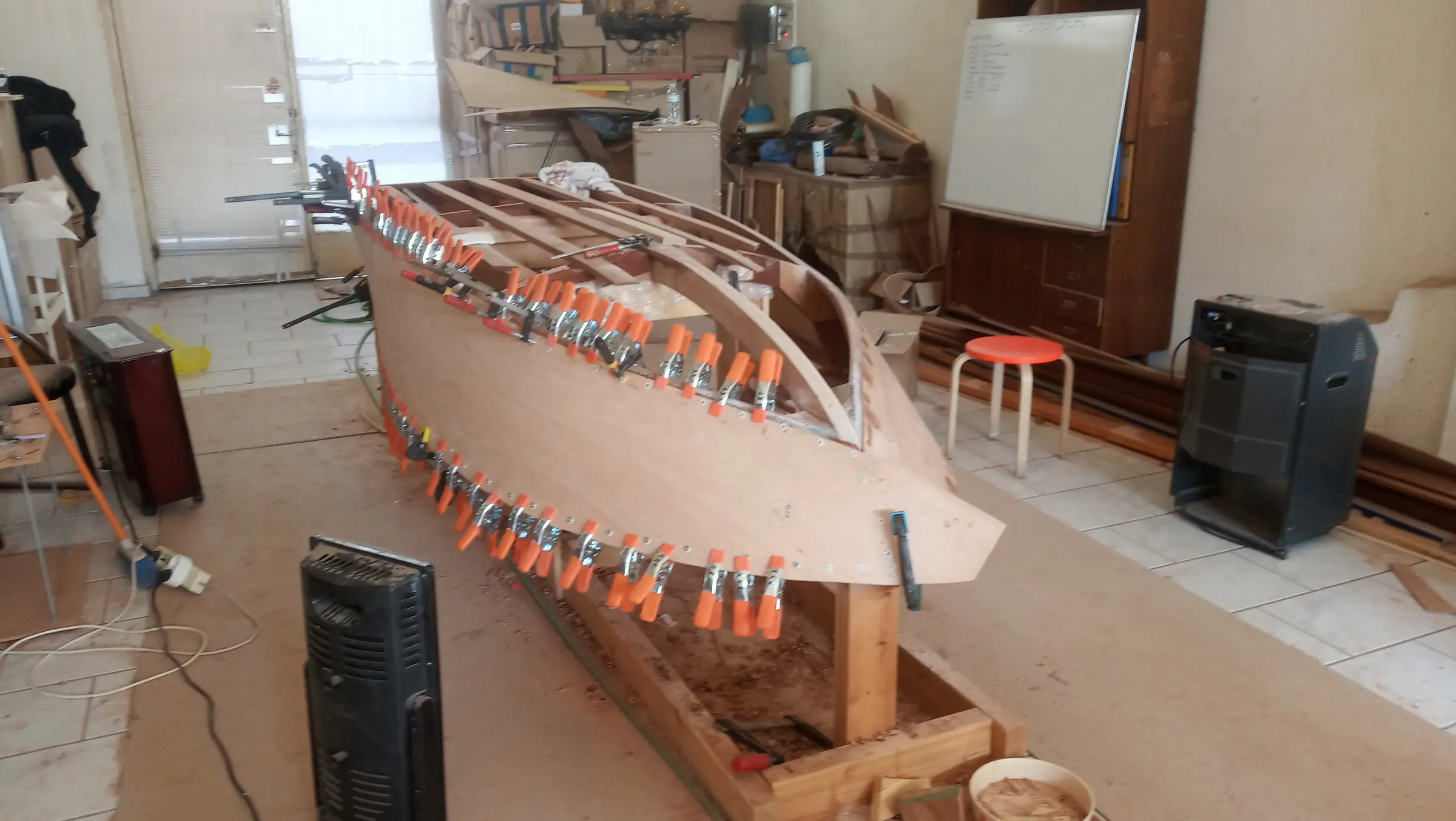
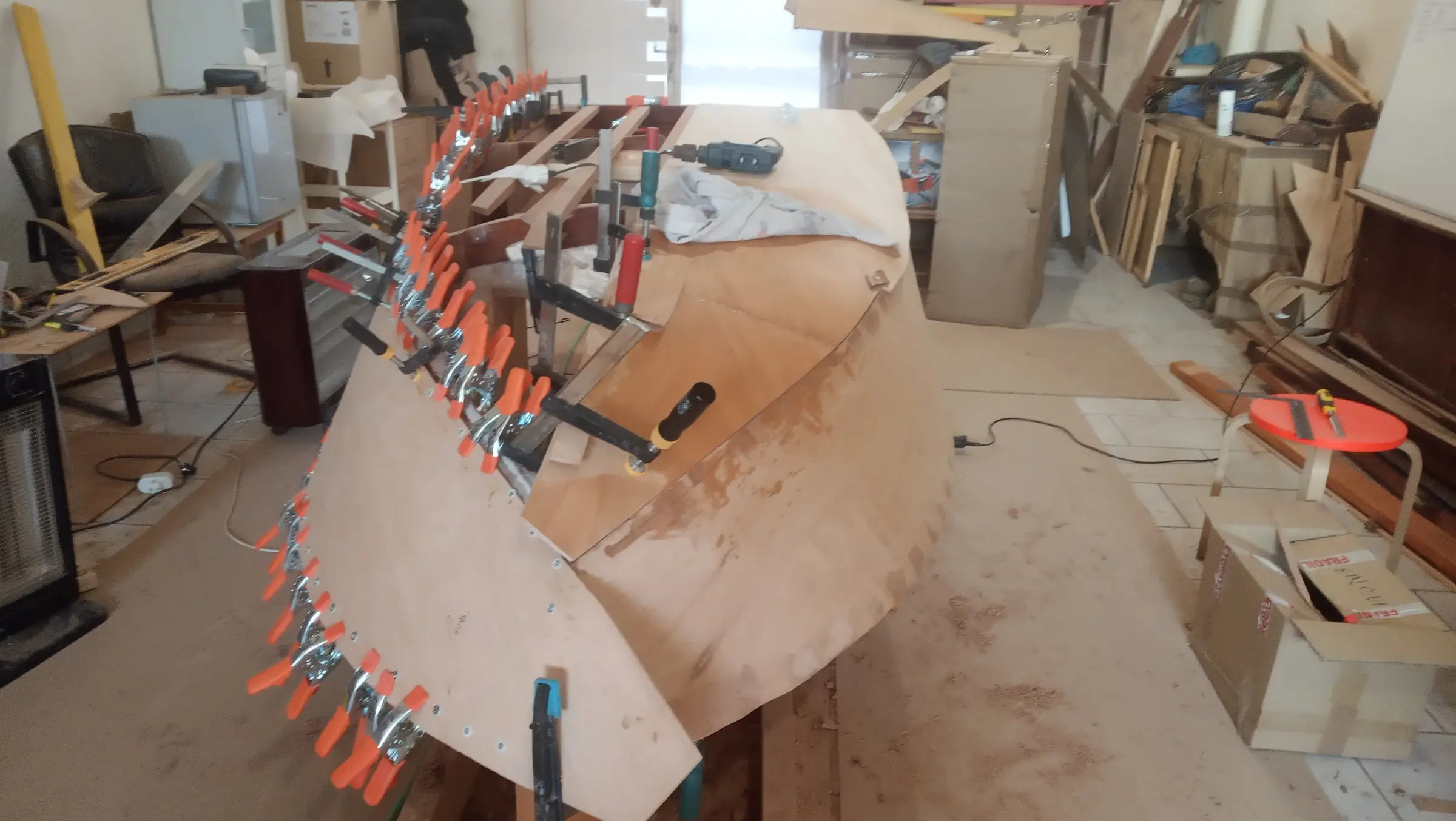
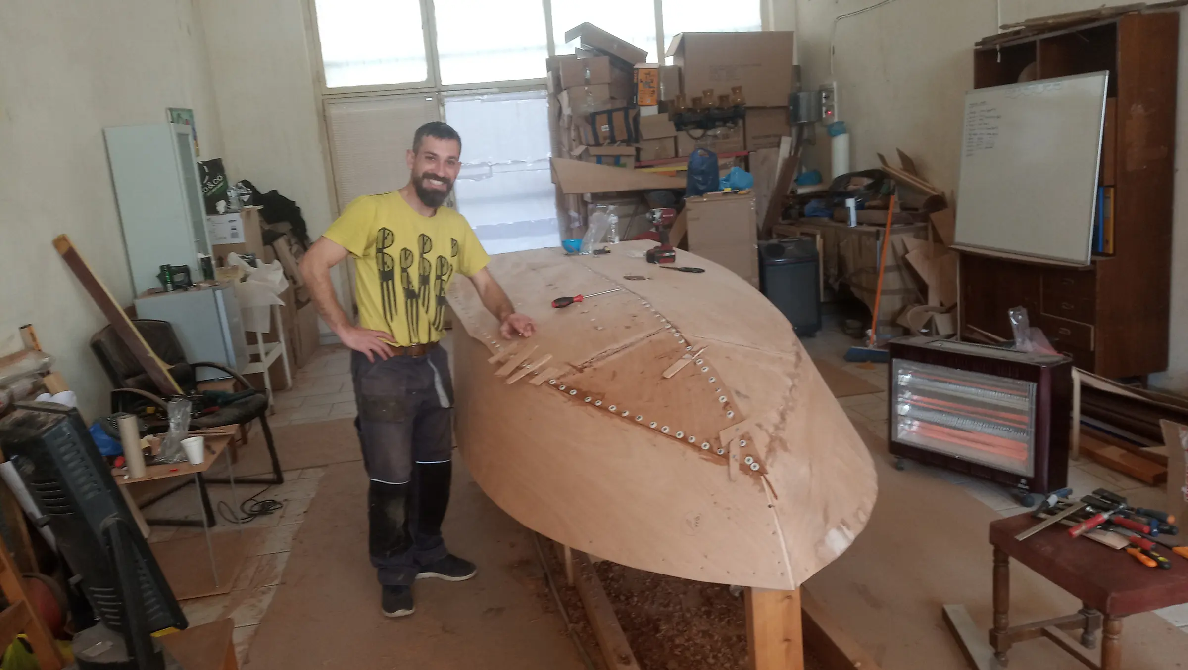
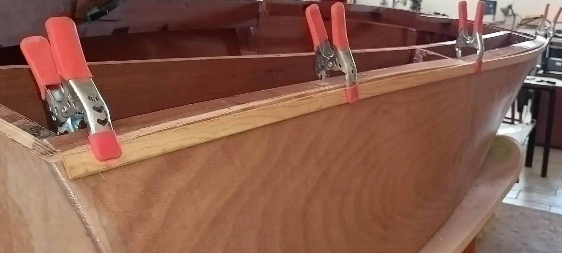
First the side panel was shaped and screwed temporarily onto the boat under construction. I found the curves were quite pronounced fore and aft, so I wetted them with towels, either on the boat or off it. When it had more or less taken the shape it needed, it was cut to the right dimensions with about two centimetres to spare.

The plywood must NOT be glued to the frames, only to the boat's framework (the chines and sheers, the timbers that run lengthways). This looks odd, but it is presumably so that vibration is not transmitted into them. Because the areas under the frames cannot be coated with resin after gluing, and not easily with paint either, I gave them two coats of resin before gluing to seal them.

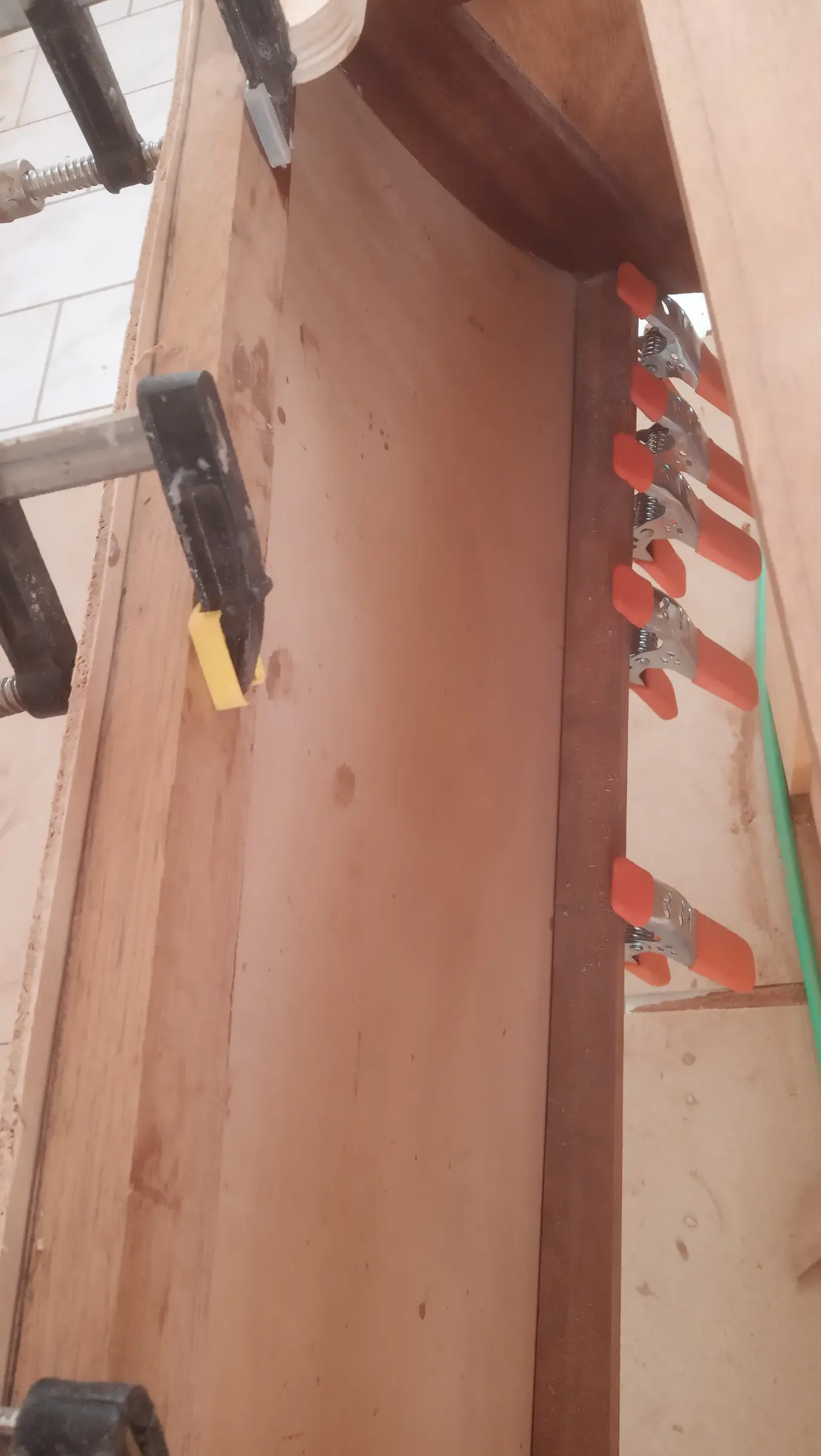
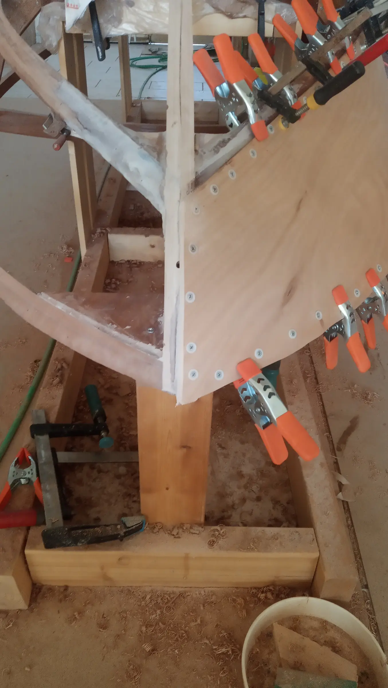
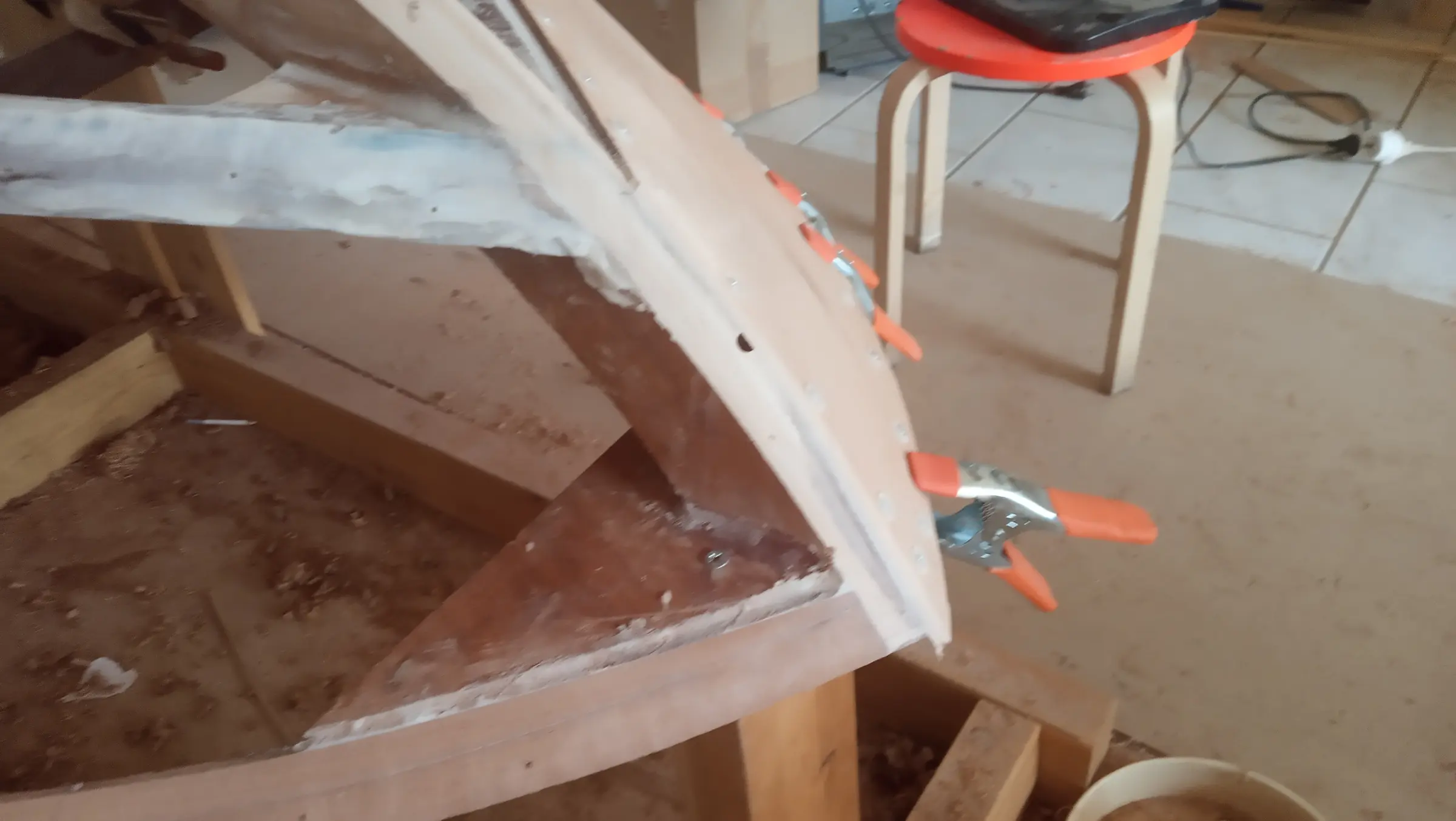
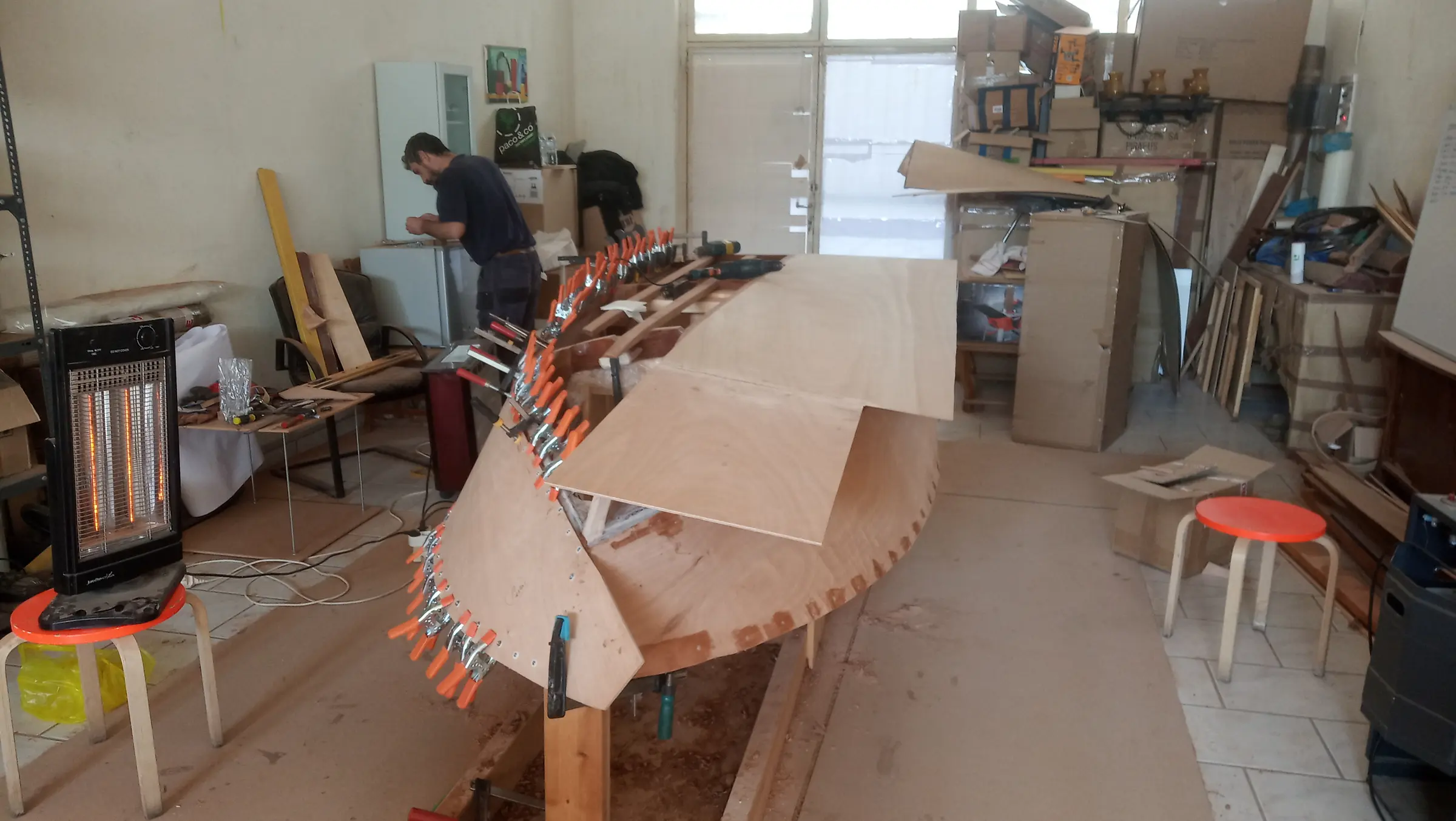
The plywood was screwed back onto the framework in its exact position. The fit where the side panel meets the bottom plywood will work like this: up to about 70 cm from the bow, the bottom plywood laps over the side. After that it changes and has to fit inside it and onto the framework. Look at the photograph where that changeover happens, and later, when fitting the bottom is described, it will make more sense with more photographs and video.

Because the bottom has to fit perfectly at the bow, the fit had to be right there too. My friend Stratos from Livadi in Arcadia (a village next to Leonidio) came to help with shaping and gluing the plywood, and his help was decisive!!!

After that work, the sides are ready to be glued one at a time, once the framework has been checked for errors in the fit.

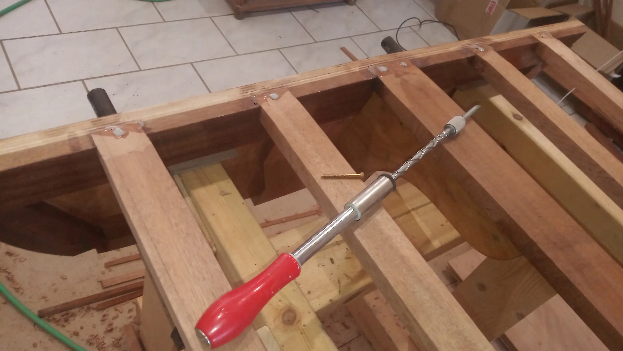
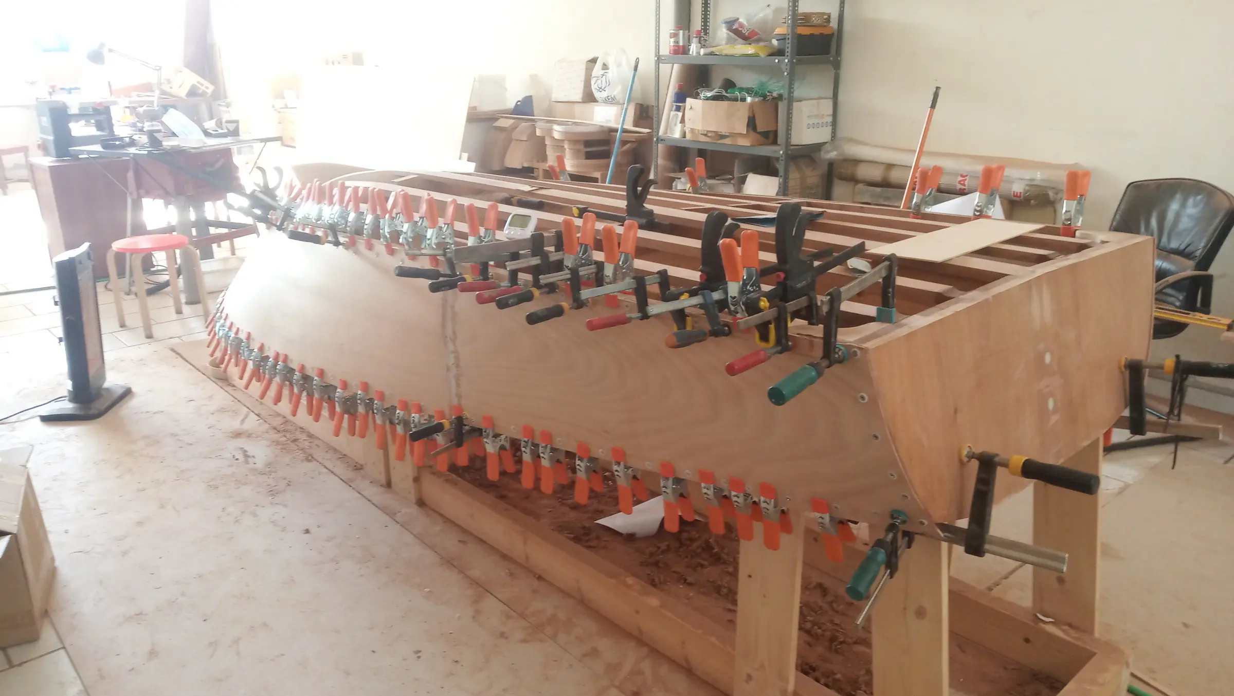
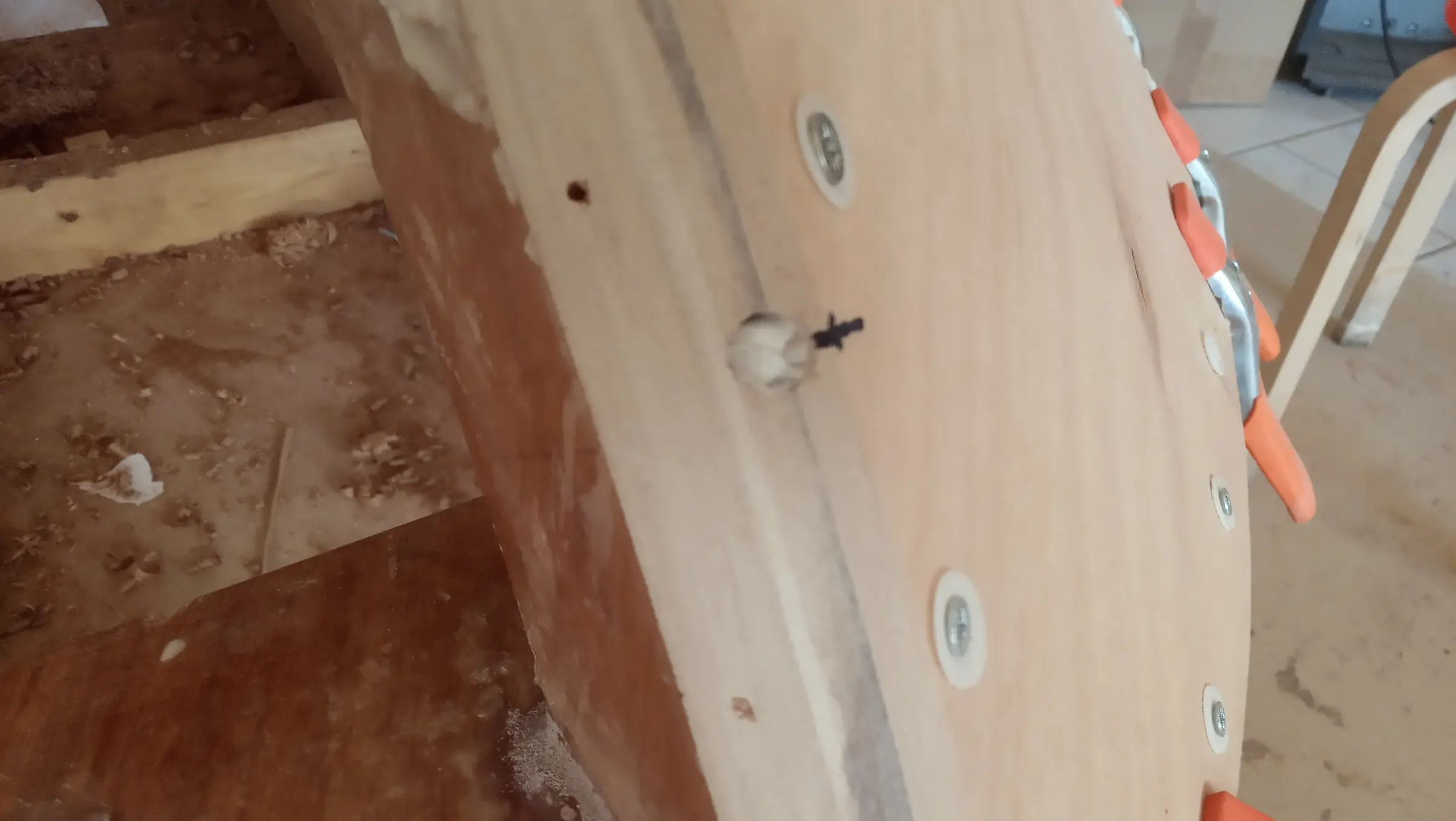
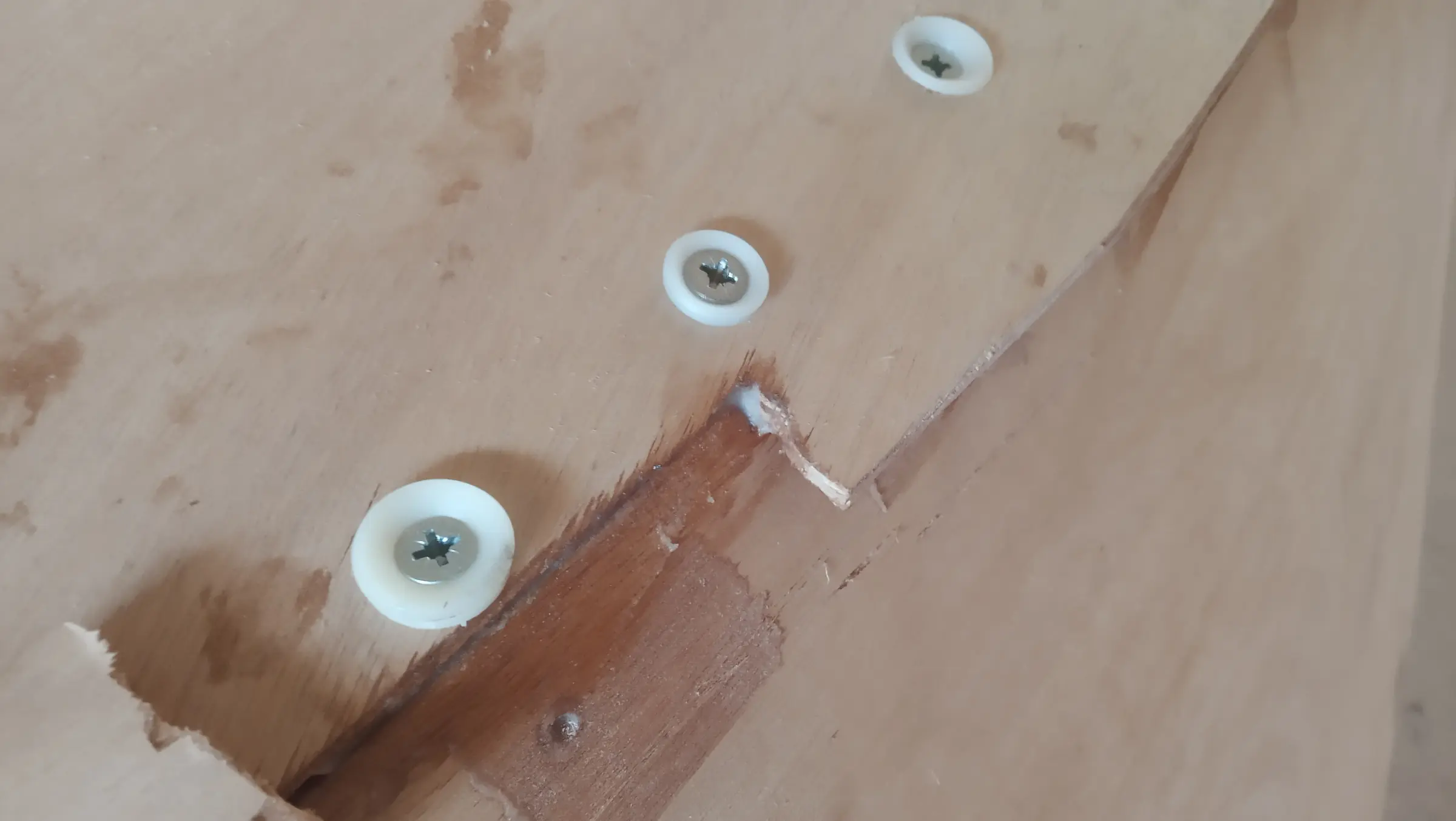
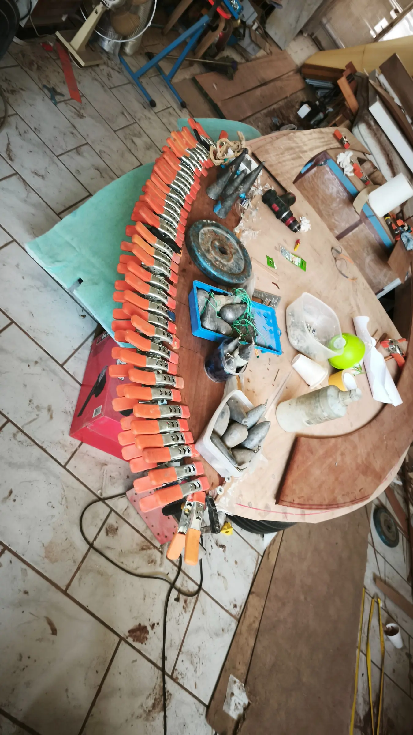
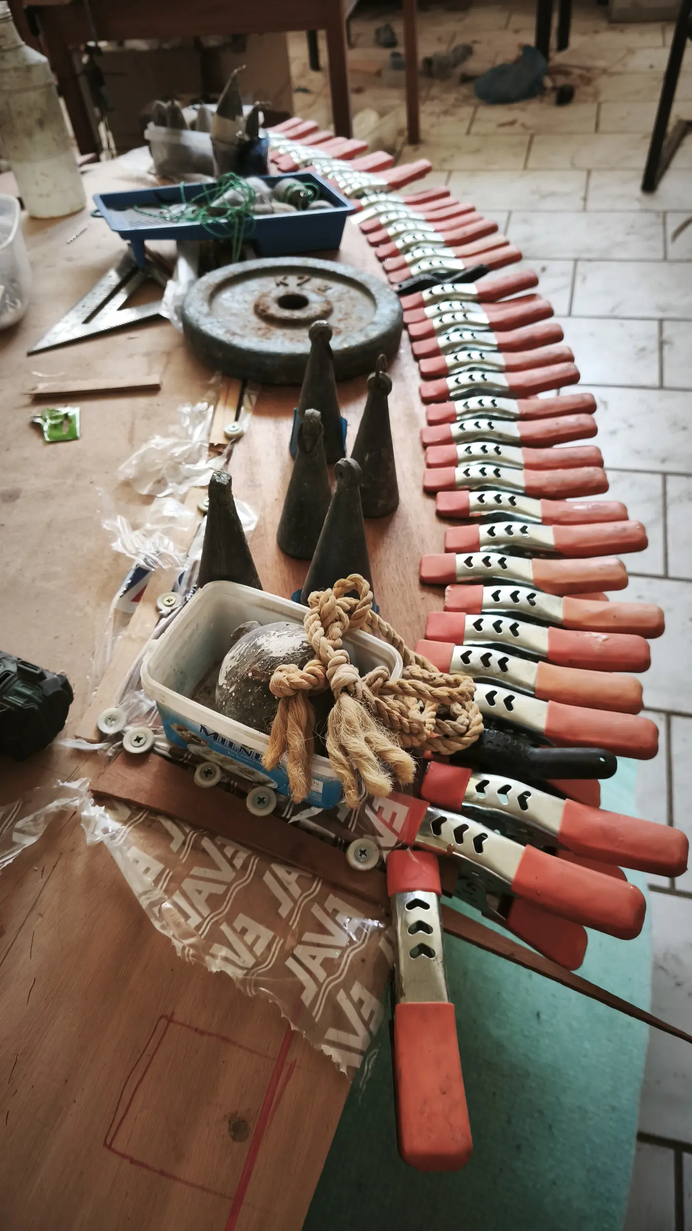
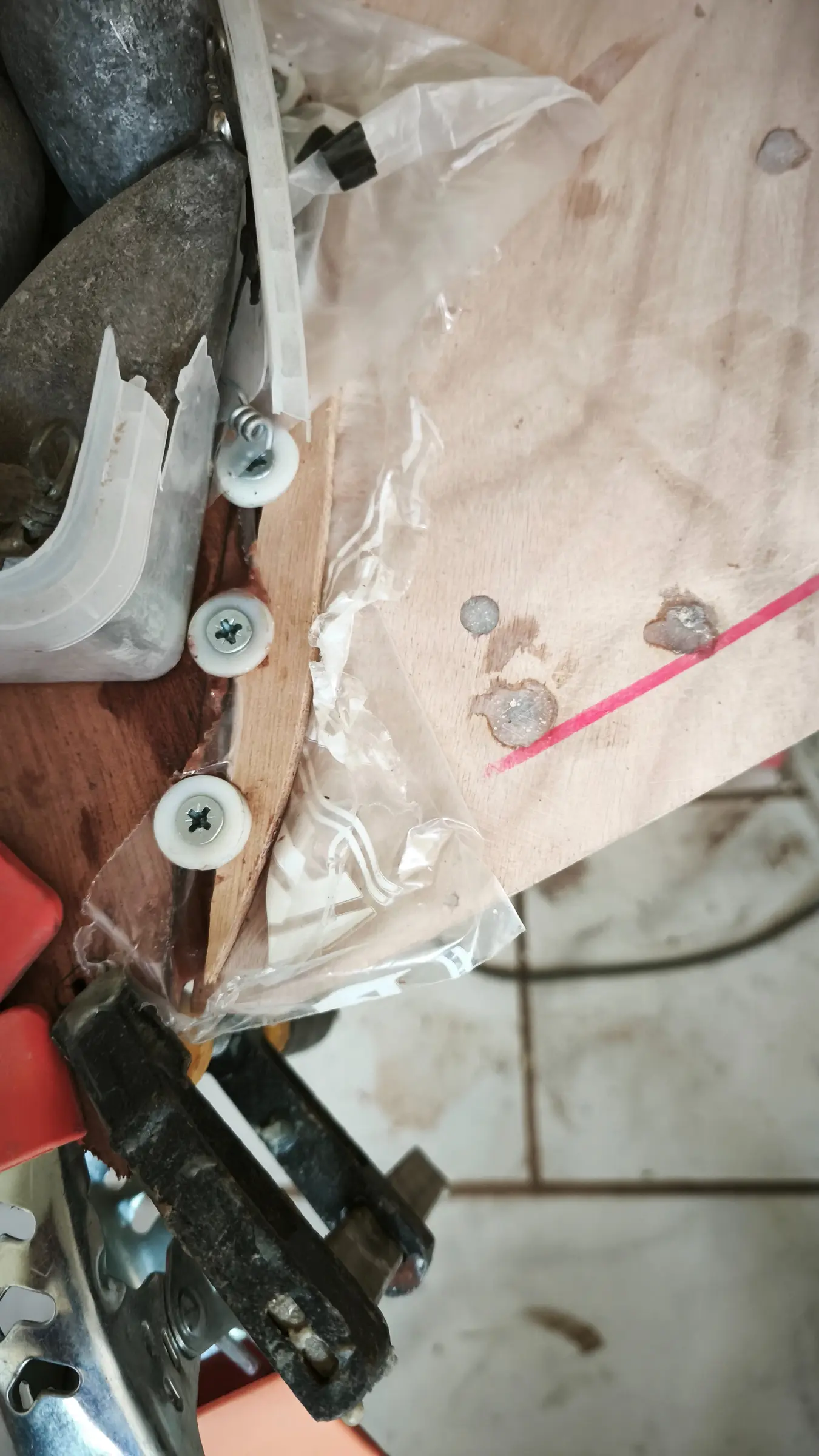
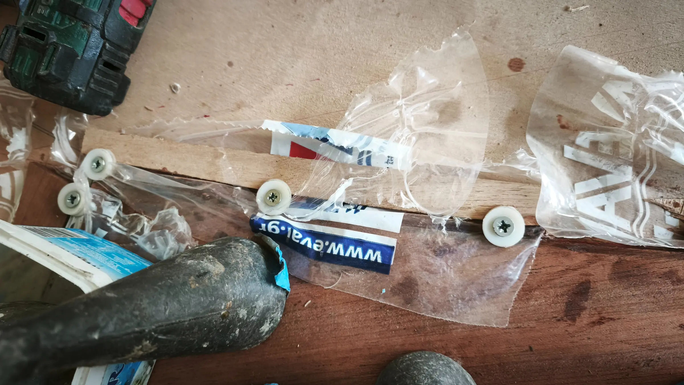
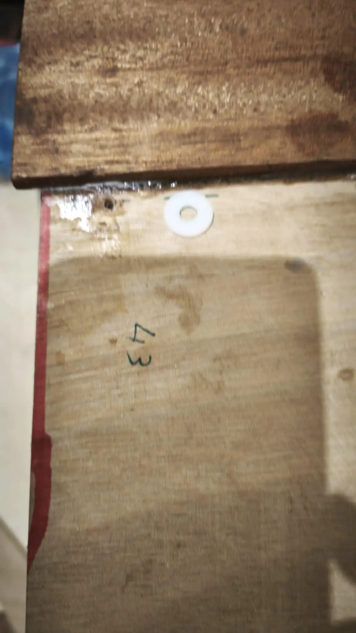
Plastic washers were used for the glue-up, for two reasons. First so the plywood is not damaged too much by the screw head, and second to reduce the chance of the screw gluing itself into the wood (keeping the resin inside the timber only). Ten to twelve hours after gluing I turned every screw half a turn to break it free (slackened and immediately retightened), before the resin got too hard. I had read that you can use some kind of lubricant (soap, wax and so on) to stop them sticking, and that it is a good idea to use stainless if the worst happens, but none of that is needed if the screws are turned a little at the twelve hour mark.

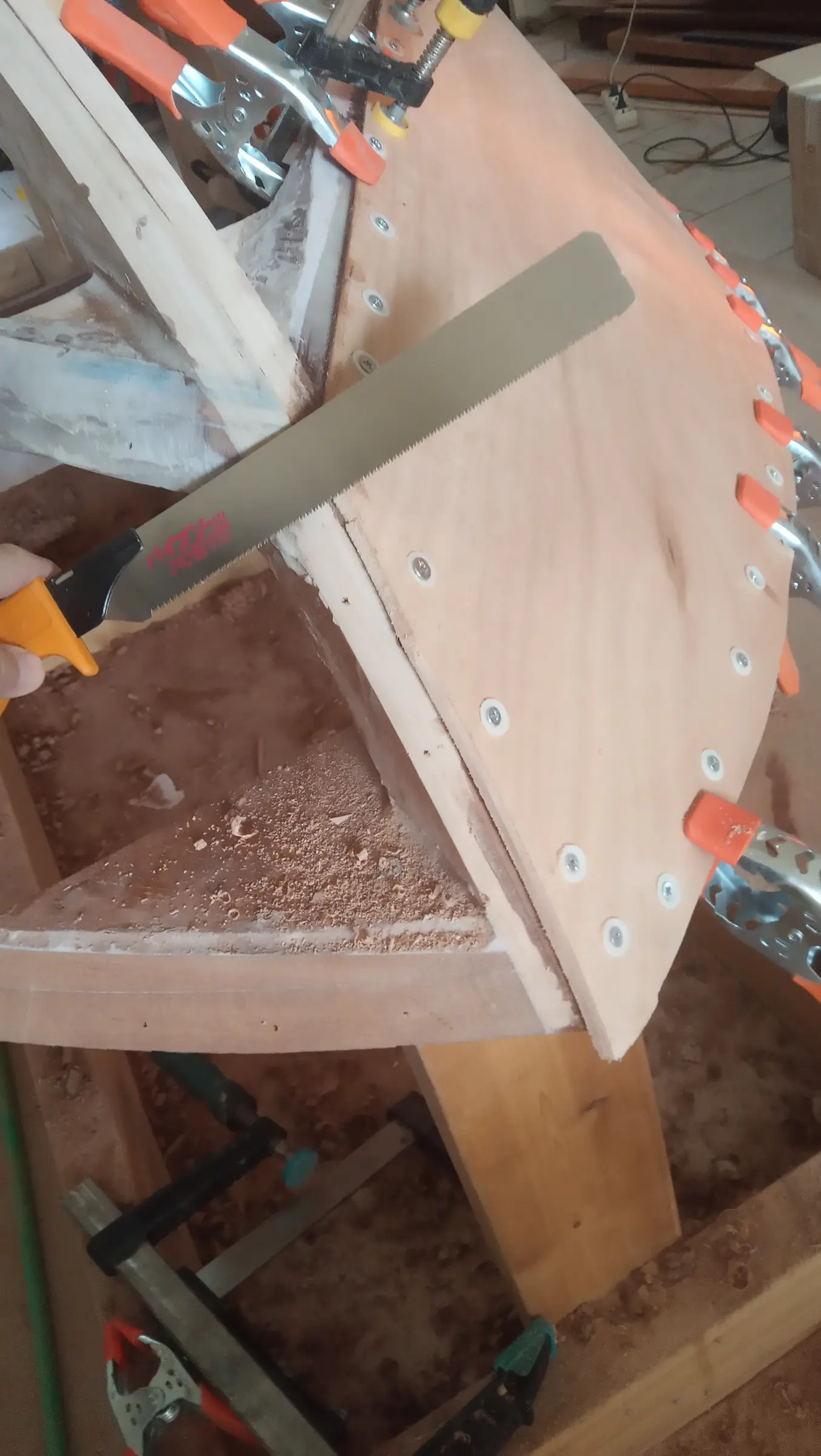
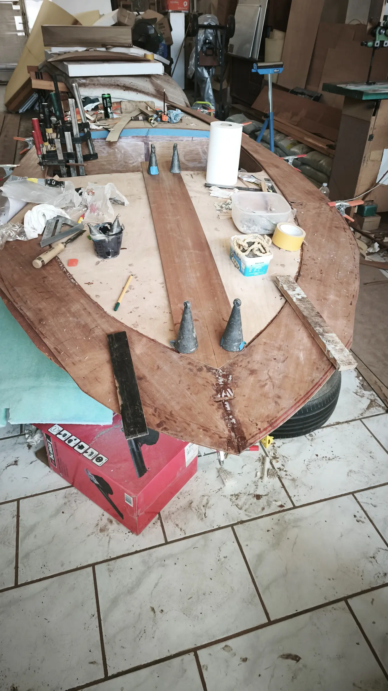
Then the excess at the bow was cut off so the second side panel would fit. It had not been cut from the start because it helped me follow the curve with a clamp resting against it. A hole was drilled in the plywood where the mooring cleat goes. The hole in the keel had been drilled earlier. It was then sealed with a plastic bag so it would not fill with resin.

The same was done on the other side. A few more photographs, again with Stratos.

While the second side was drying, we cut the first half of the boat's bottom to the right dimensions (the top, as it sits on the base), having first cut off the excess from the side panel so it followed the bevels of the framework.

As written earlier, over most of the boat the bottom plywood laps over the side panel, so on the outside we have no problem, we simply leave a centimetre or two to spare. On the inside, up to the point where the curve of the keel begins, it is a straight line, so no problem there either. The difficulty is only in the forward section on the outside. On the inside I will probably have to follow the line, which gets lost because of the curvature of the keel. Below are some photographs of the fitting and a short video of Stratos with the hand plane. Until the side was properly glued and I could take the clamps off, it was wetted with towels so it would take the curves as easily as possible.

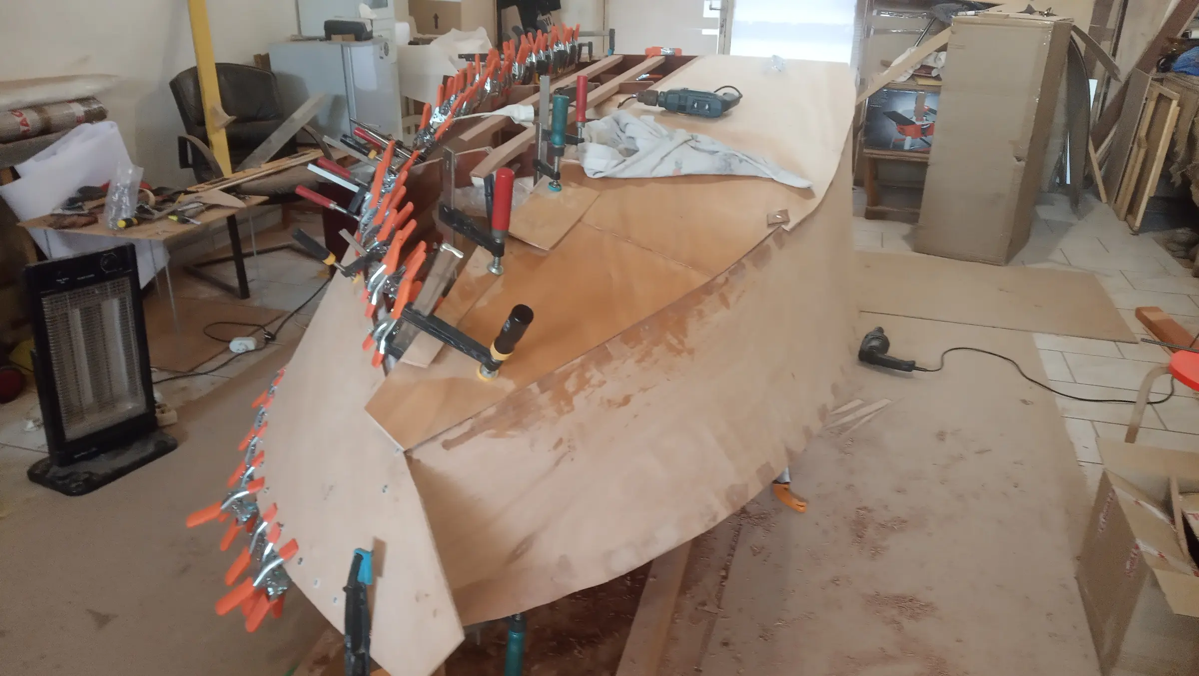
Once the third piece was glued it was shaped at its forward end. The method used is this: from the bow to about 70 cm back, the second bottom panel laps over the first. After that it changes and the two sheets run parallel. The opposite happens between the second bottom panel and the side. At the bow the bottom meets the side flush, while over the rest of the boat it laps over it. Fitting the fourth piece was the hardest, because it had to be shaped correctly on both sides. Some photographs of the fourth glue-up.

Video: https://www.youtube-nocookie.com/embed/voCmhL5KW8k


33.5 h

Hull work and fiberglassing

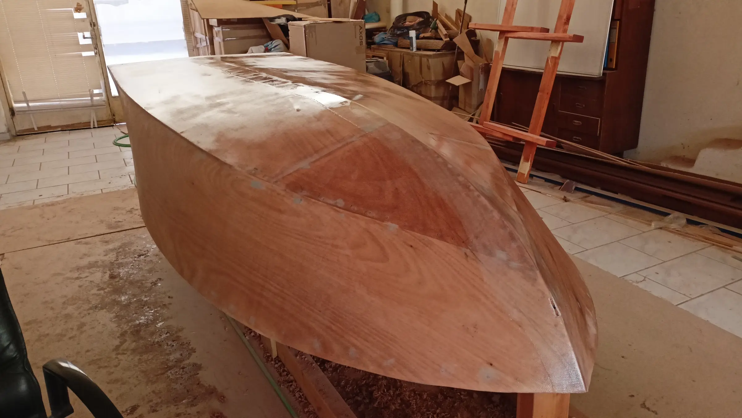
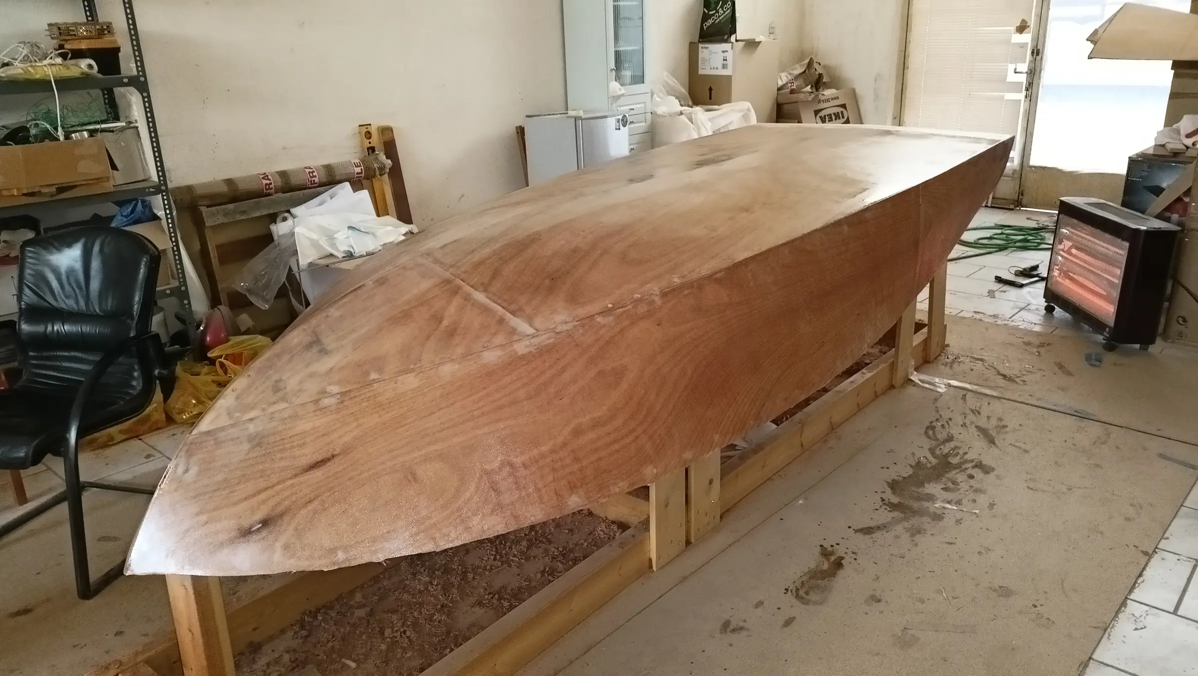
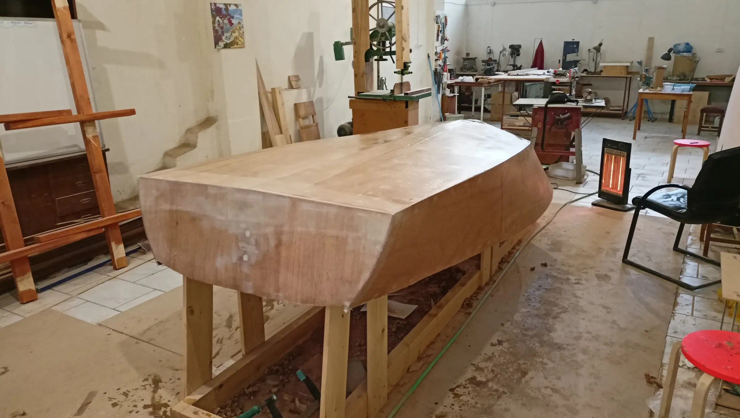
This post covers the work done to finish the boat's hull. The screw holes have to be filled with epoxy, it has to be sanded with a sander, and then it has to be covered with fiberglass cloth.

First the hole was drilled in the plywood where the forward mooring cleat will be fitted. I should point out that the hole in the keel had been drilled before it was glued to the rest of the boat, and obviously before the plywood was glued on. That had the advantage that the job was done on the drill press, with a very accurate result.

Once the holes were filled with epoxy and microfibre, and epoxy fairing filler, the boat was sanded with 80, 120 and 180 grit.

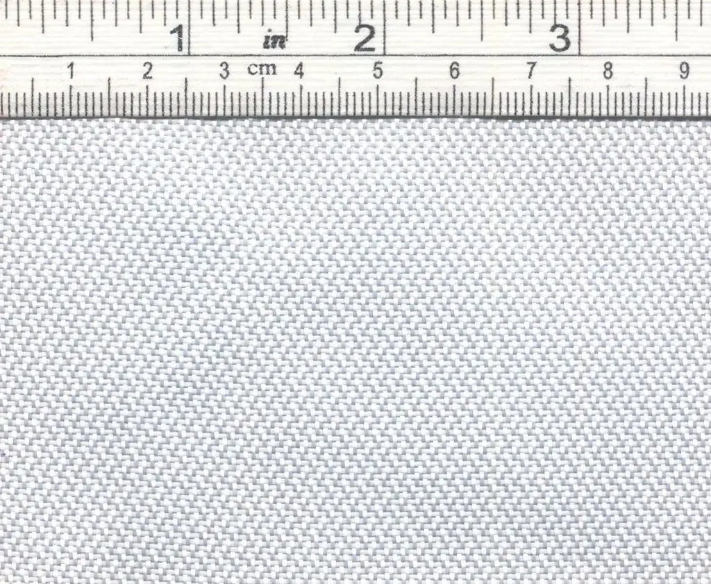
The boat is ready for the fiberglass cloth. I chose the dry method: the cloth is laid onto the boat without first wetting it out with resin. Initially I chose West System 742, which is 200 g/m2 and 150 cm wide. I wanted to use two pieces, one to the left and one to the right of the keel with an overlap over it (and one on the transom, of course). The maximum width I need is 115 cm, so most cloths at 100 cm wide were ruled out. Unfortunately that cloth was not available for immediate delivery, so I kept looking. I ended up with Fiberglass fabric G213S from FIBERMAX Ltd, weight 213 g/m2, 120 cm wide, with the following specification:

Areal weight: 213 g / m2 Weaving style: Satin Width: 1.20 meters Warp: Glass EC9 68 fiber, 61%, 19 ends (threads) / cm Weft: Glass EC9 68 fiber, 39%, 12 ends / cm Tensile strength on yarn (N): 48

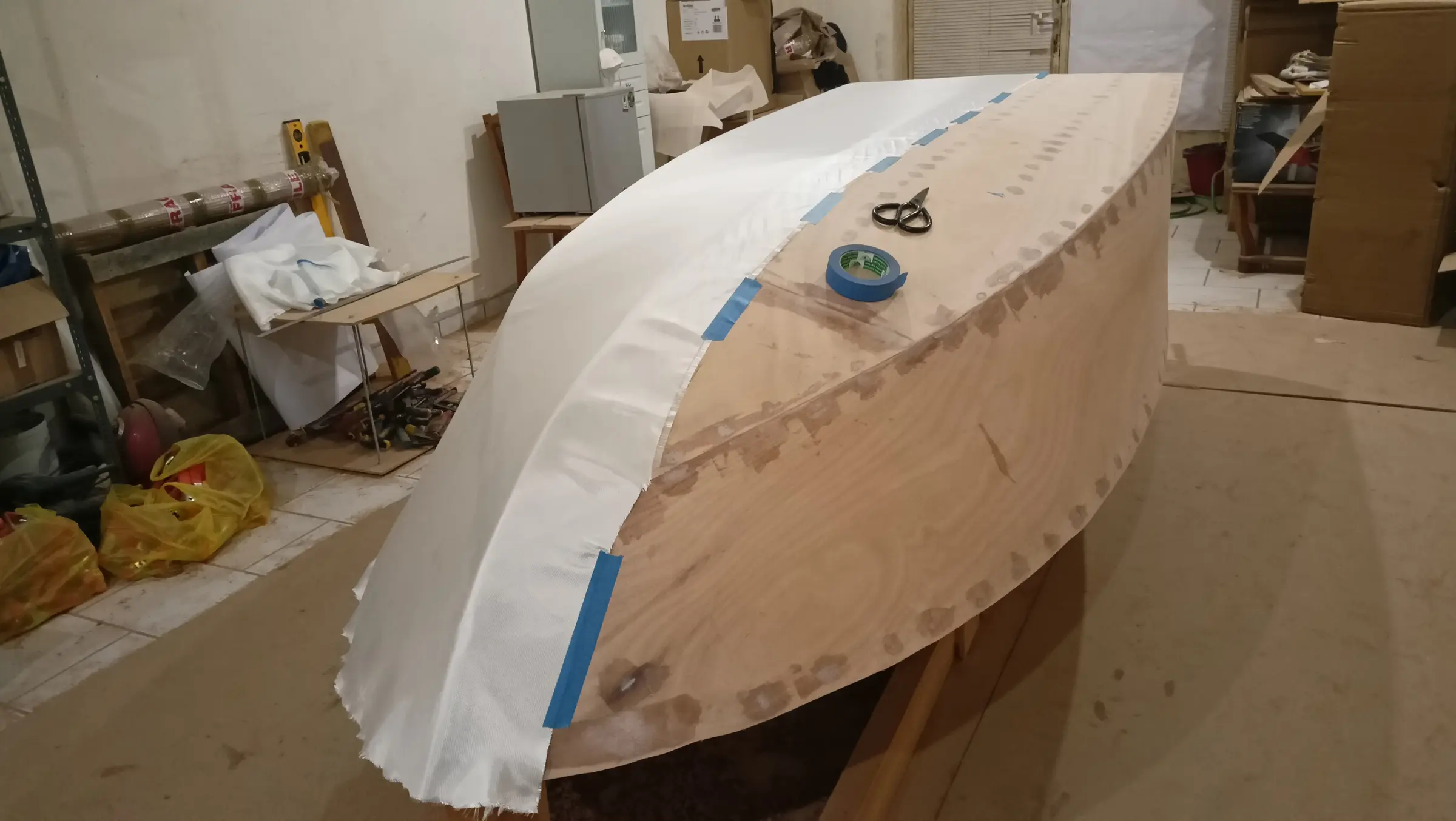
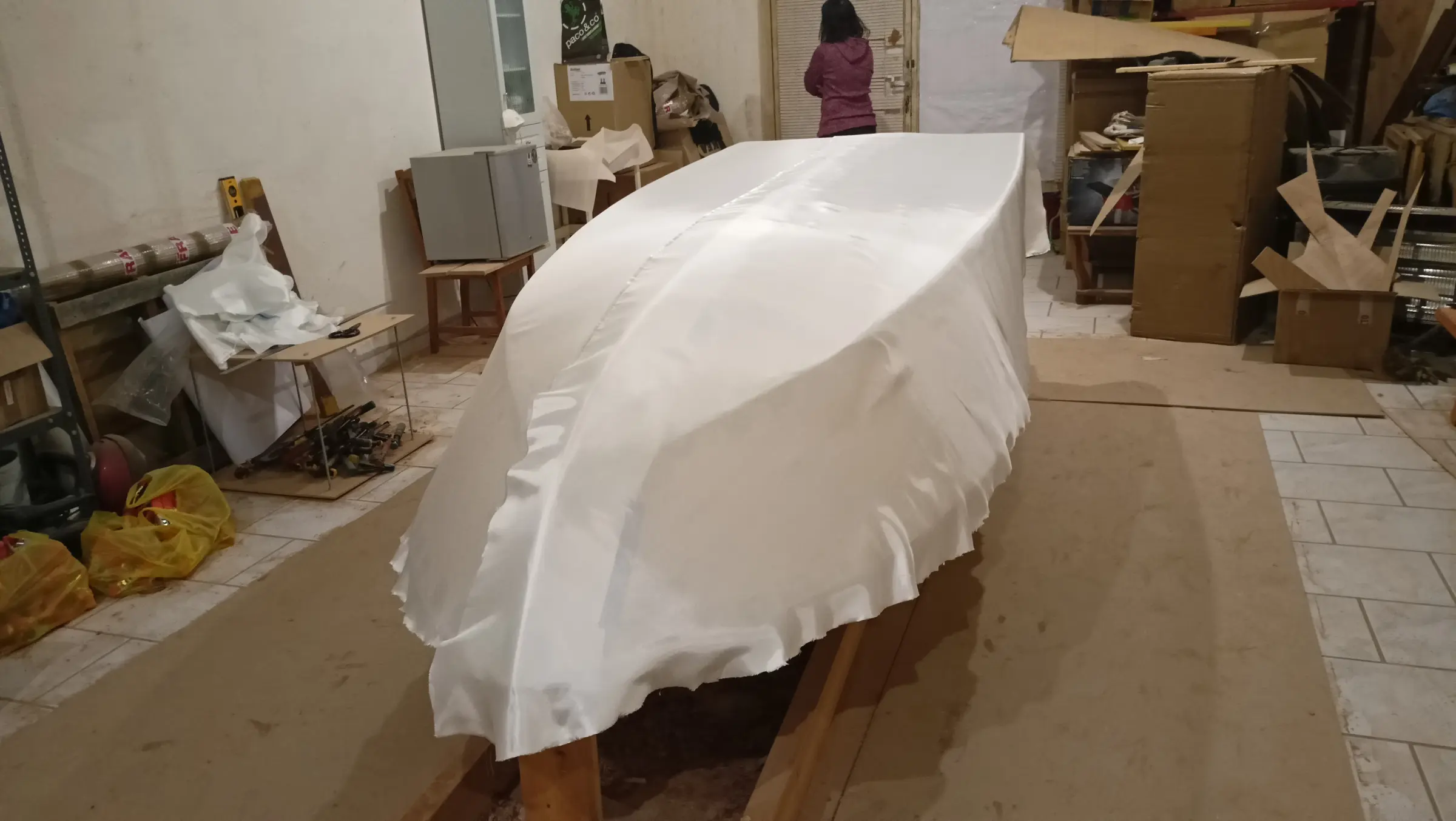
First the cloths were laid over the boat and cut to shape. The resin was rolled onto one side and then the other. At the keel the cloths overlap by about 10 cm either side of it. When one side had been wetted out, the other had lifted. I was struck by how much resin the first coat took to wet the cloth out. About 3.5 litres, spread with a plastic squeegee. For the second coat 700 ml went on with an 18 cm West System roller (product code 800), which is very thin so it does not hold much resin. Some photographs of the process.

The next coats will go on once the resin has cured. To do that it has to be washed with water and a stiff sponge to remove the amine blush. This is a waxy film that forms on a cured epoxy surface and is a by-product of the curing process. It is water soluble and comes off easily. After washing, the boat is wiped down with clean absorbent paper. It is then sanded with 80 grit and the dust removed.

That process was not needed between the first and second coats, because it is not necessary while the resin has not finished curing (the second coat went on about 8 hours after the first, at around 18 degrees Celsius). The same will apply between all the remaining coats from the third to the last, whichever that turns out to be.

I decided to leave the next coats of resin, making a small skeg, and painting the hull, to a later stage. First because the temperature is still quite low (minimum for the resin is 16 degrees) and second, and more importantly, because I would rather shape the top edge of the boat all the way round first and paint afterwards, so as not to damage painted surfaces.

So the boat is ready to be turned over. To do that a new base had to be made, which will sit on top of the first once that has been cut down a little. Some photographs of the second base, which was made shortly before the cloth went on, though the order obviously does not matter:

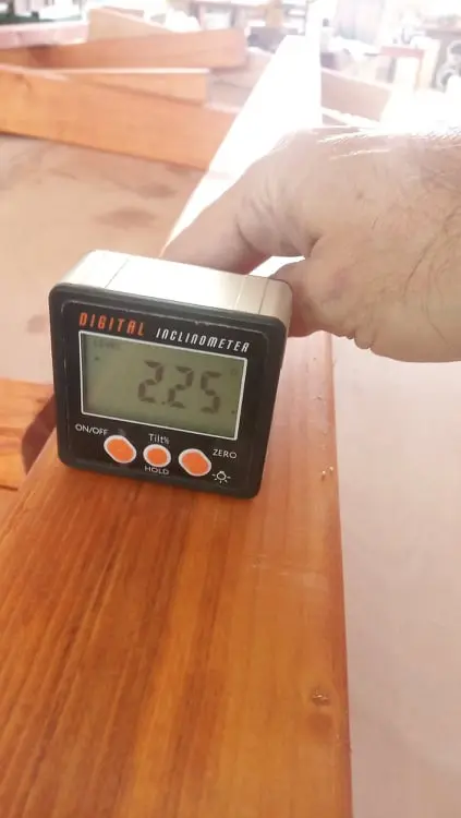
Because the long parallel timbers are not square to the plane of the lower base, wedges had to go in so they could be screwed at the right angle. To do that the angle was measured and suitable wedges cut.

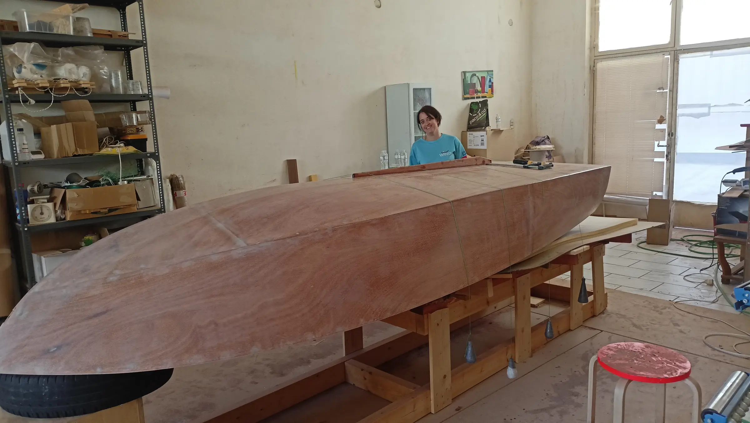
On the first base the uprights were cut down to reduce its height. The second will sit on top of it. To turn the boat over I had thought of using a mattress, but in the end I used car tyres. The boat is still very light and the two of us had no trouble at all turning it over. Fortunately it had not glued itself to the first base with resin (where there was a risk I had put plastic bags down before gluing). Cardboard was laid on the second base and foam on top of that. Some photographs of the process and of Stratos load-testing it.


22 h

First work on the inside

One job that definitely had to be done was cleaning up the inside of the boat where resin had run. Also reinforcing the uprights the plywood was glued to, with resin and microfibre. And finally filling over the carriage bolts with resin.

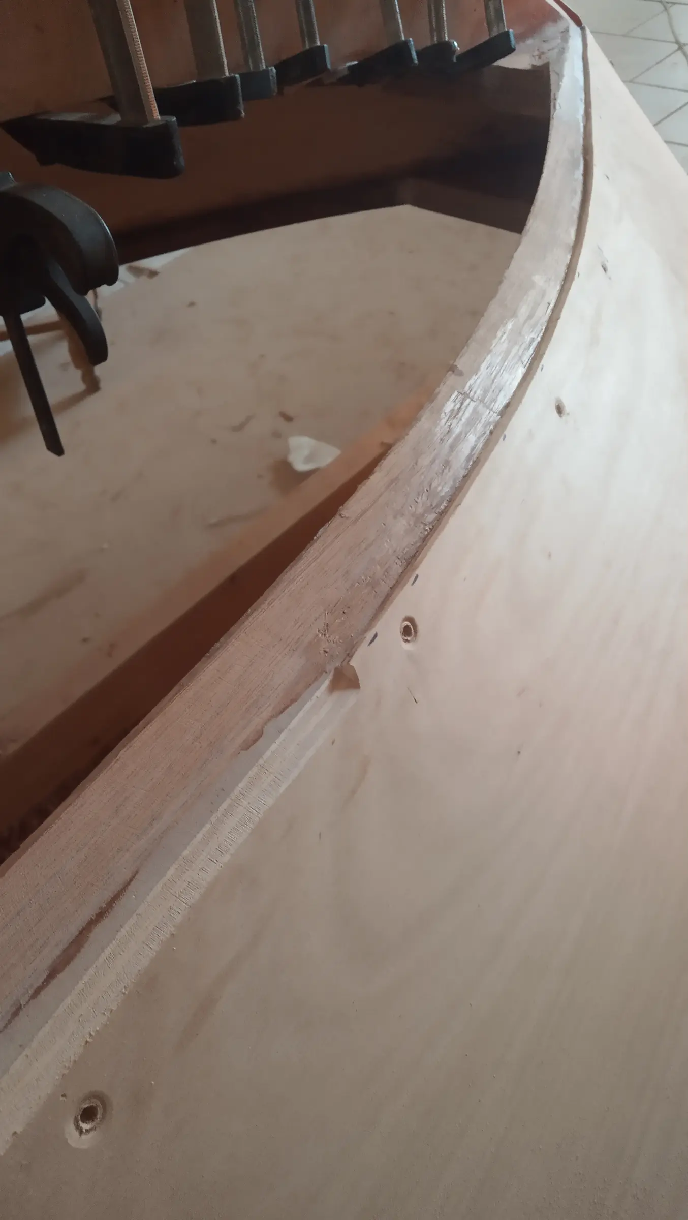
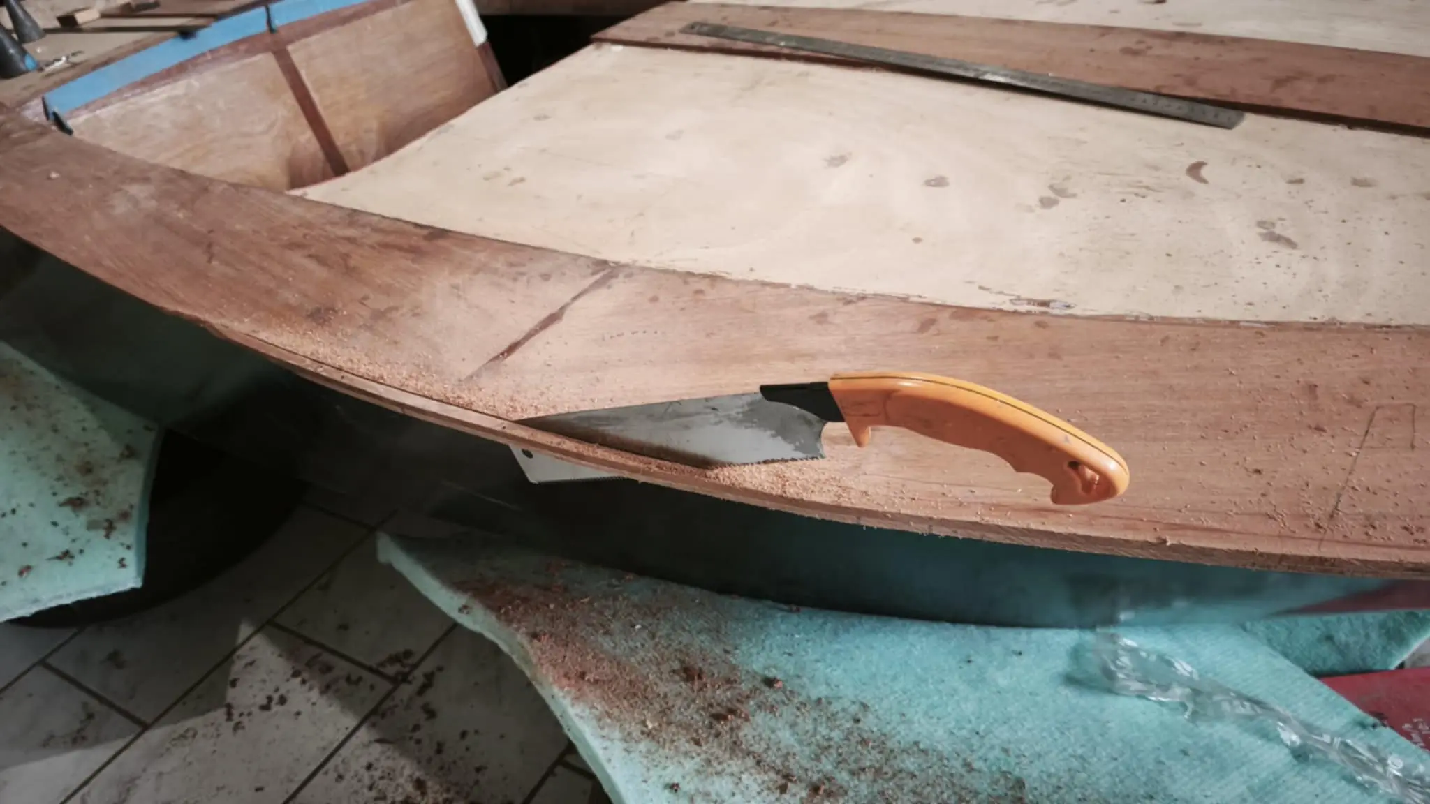
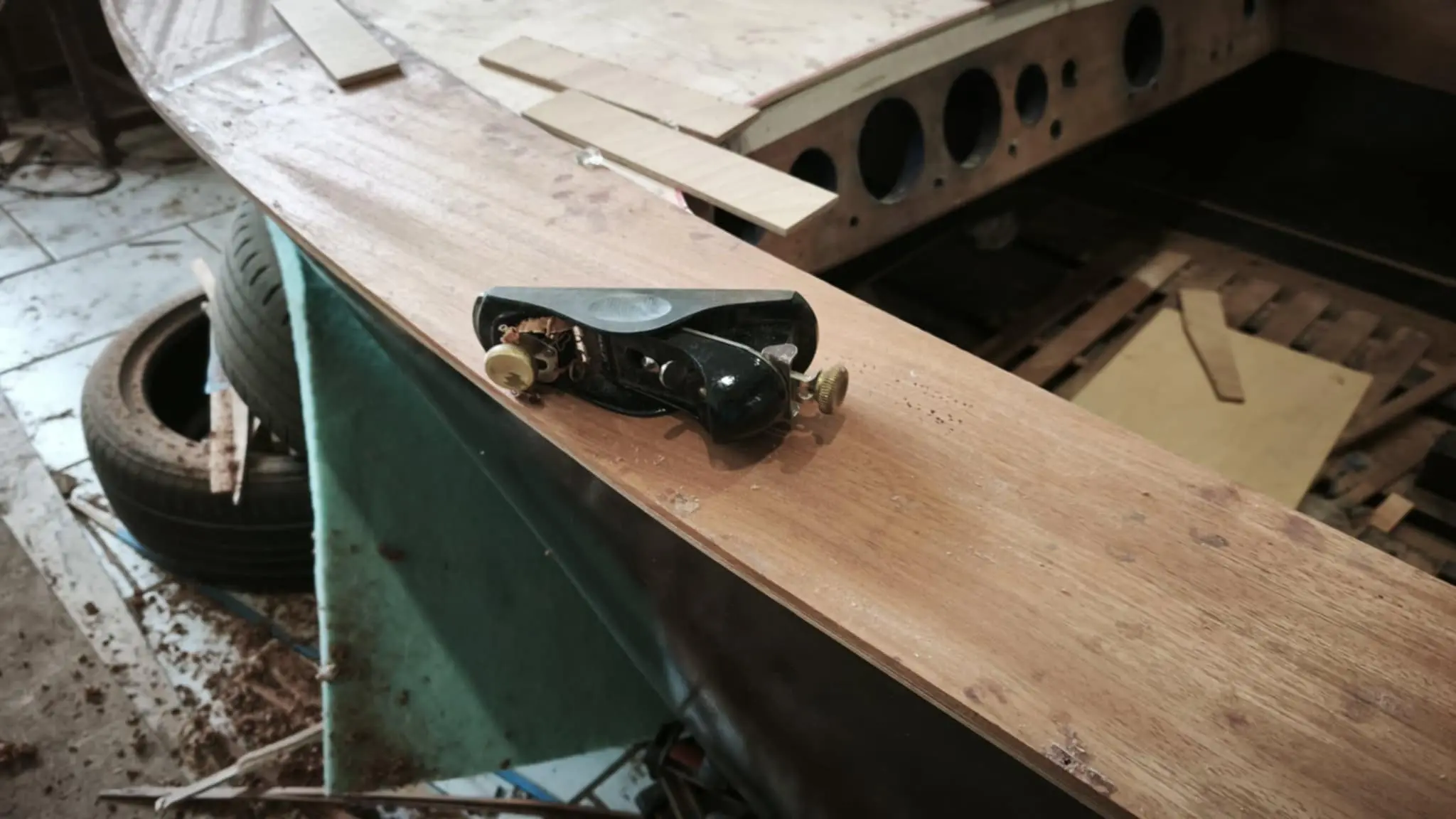
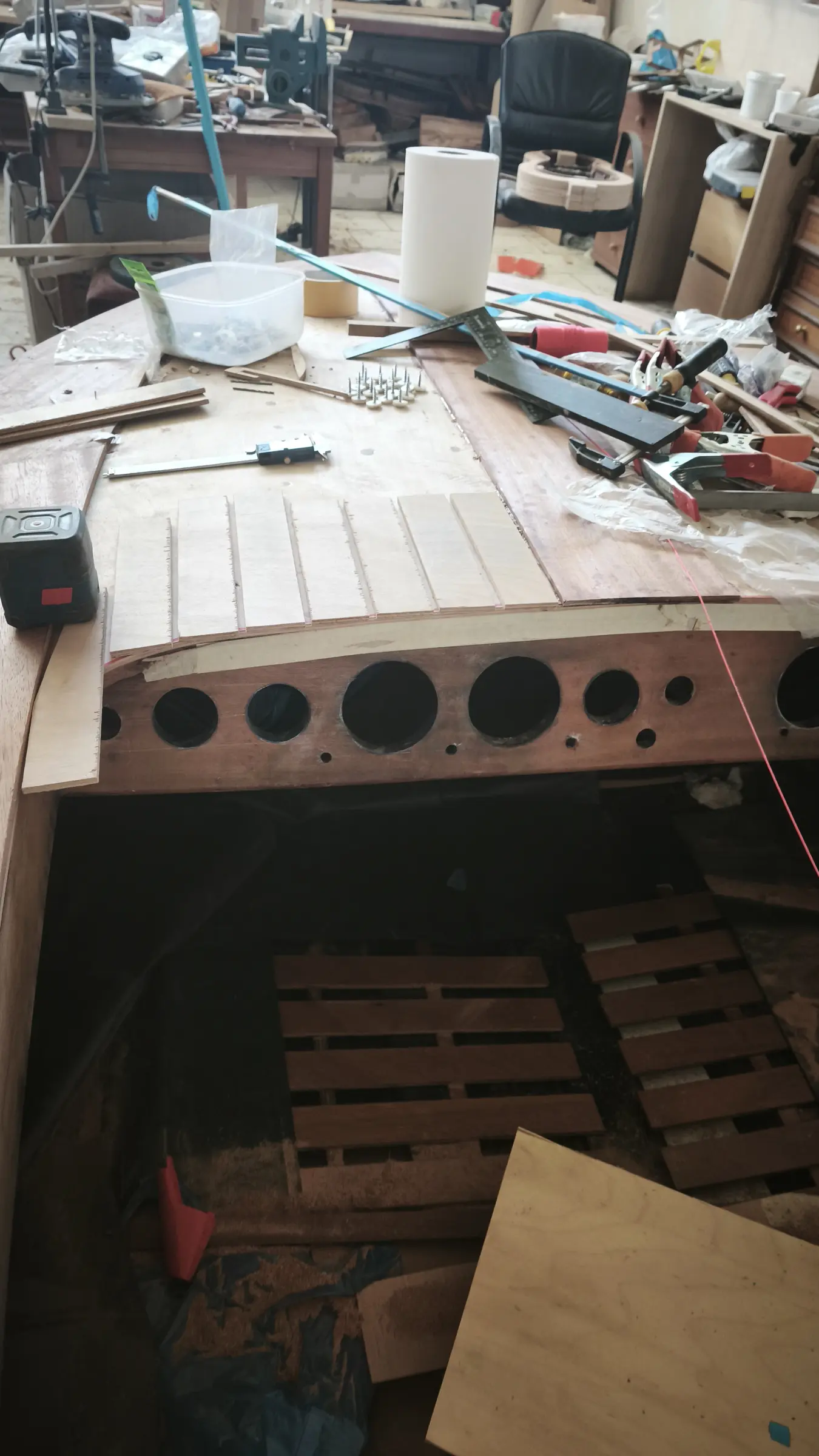
A very important job is shaping the top edge of the hull so the deck plywood can sit down on it.

The process starts the same way it did with the lengthways timbers of the boat's framework (the sheers and chines), shaping the plywood at the transom and at the frames.

The shaping will carry on once the rest of the boat's parts are fitted (deck beam, dash beam, aft deck beams, coaming, deck battens and so on).

First the lengthways timbers (the coamings) were bent for the internal shaping of the aft section. The steamer was used. They are 1.5 cm thick and 11 cm wide. To bend them to the curve I wanted, the method shown in the photographs below was used. Once the timbers had dried they were wrapped in a wet towel. Small blocks were also cut, to be used when gluing them.

At the same time I started on the forward section, marking where the first deck beam would be glued and cutting it to follow the curve of the second frame.

Once it was cut to length it was glued in place. Then the notches were cut so the forward uprights could be fitted in position. The centre one has to be glued at the bow with its thickness feathered away. Some photographs below. None of the uprights has been glued yet.

The deck beam was glued in.

The aft section of the boat is being worked on at the same time.


19.5 h

Designing and building the seat

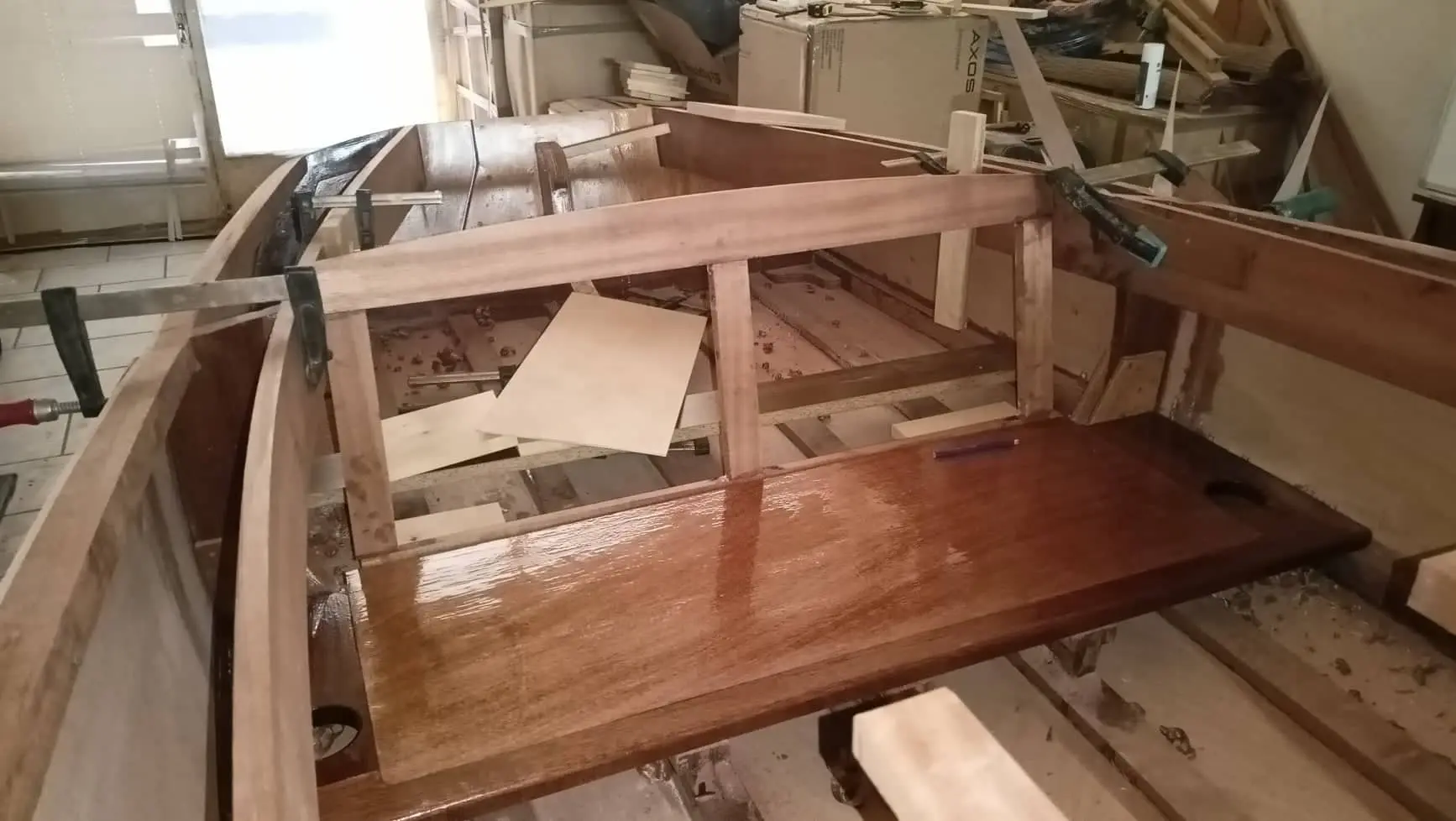
With the main framework done on the inside, I decided to make the seat. The reason is that I want to see where the dashboard with the instruments and the wheel will go, and how the seat back relates to the rest of the boat aft (the locker and so on).

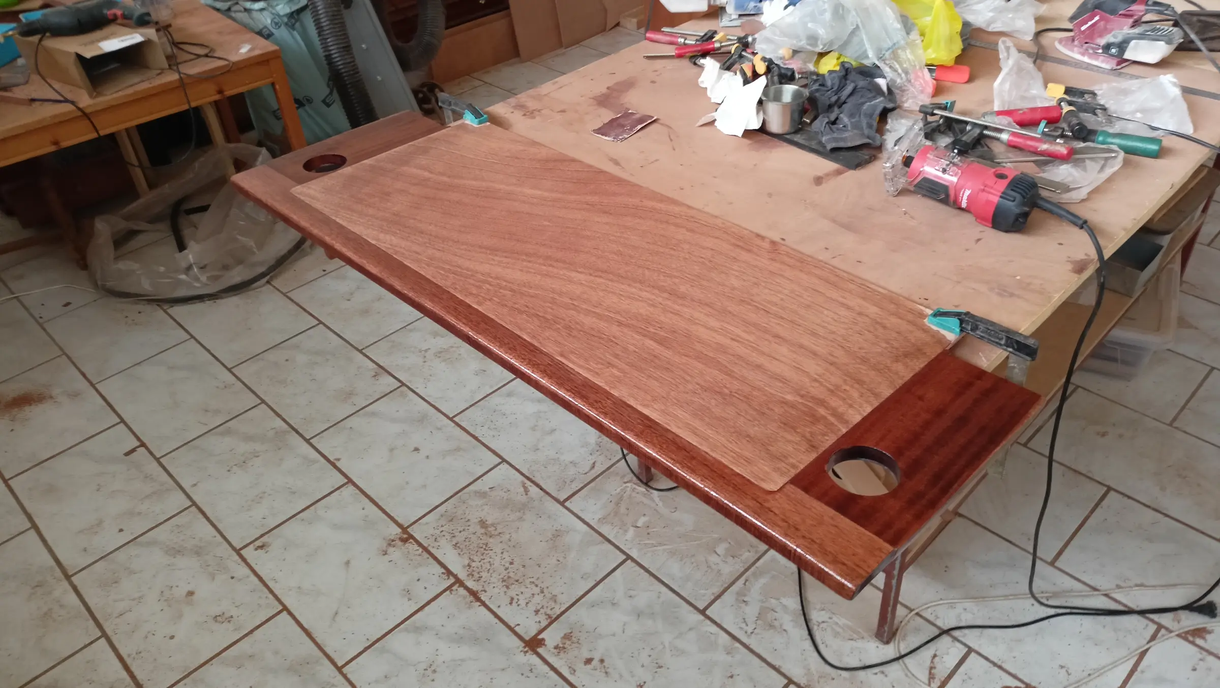
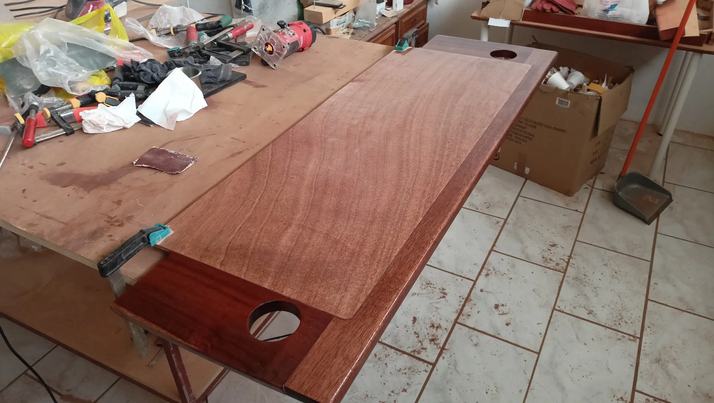
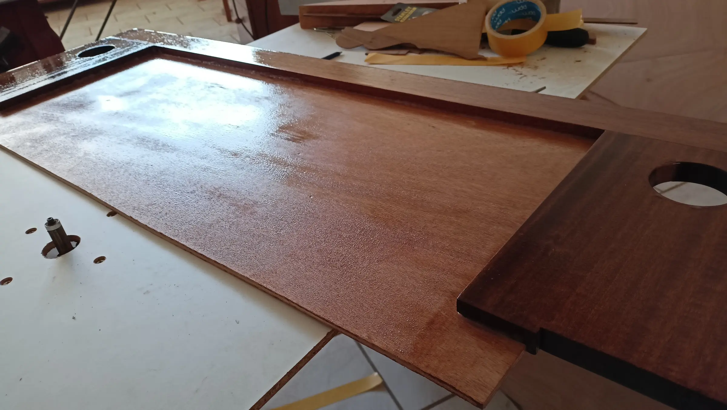
I decided the seat should have the coffee holders in it. The cup holders were among the first fittings I bought. The seat is made up of three pieces of 20 mm timber and one piece of 6 mm plywood. The timber will be routed around the edge to a depth equal to the thickness of the plywood. The drawing is below.

The seat bears on the chines around the hull, on the frame, on two blocks that will be glued to the frame, and on 3 pieces on the bottom of the boat glued to the bottom stiffeners. All of these have to be at the right height so the seat sits properly. Some photographs of the work.

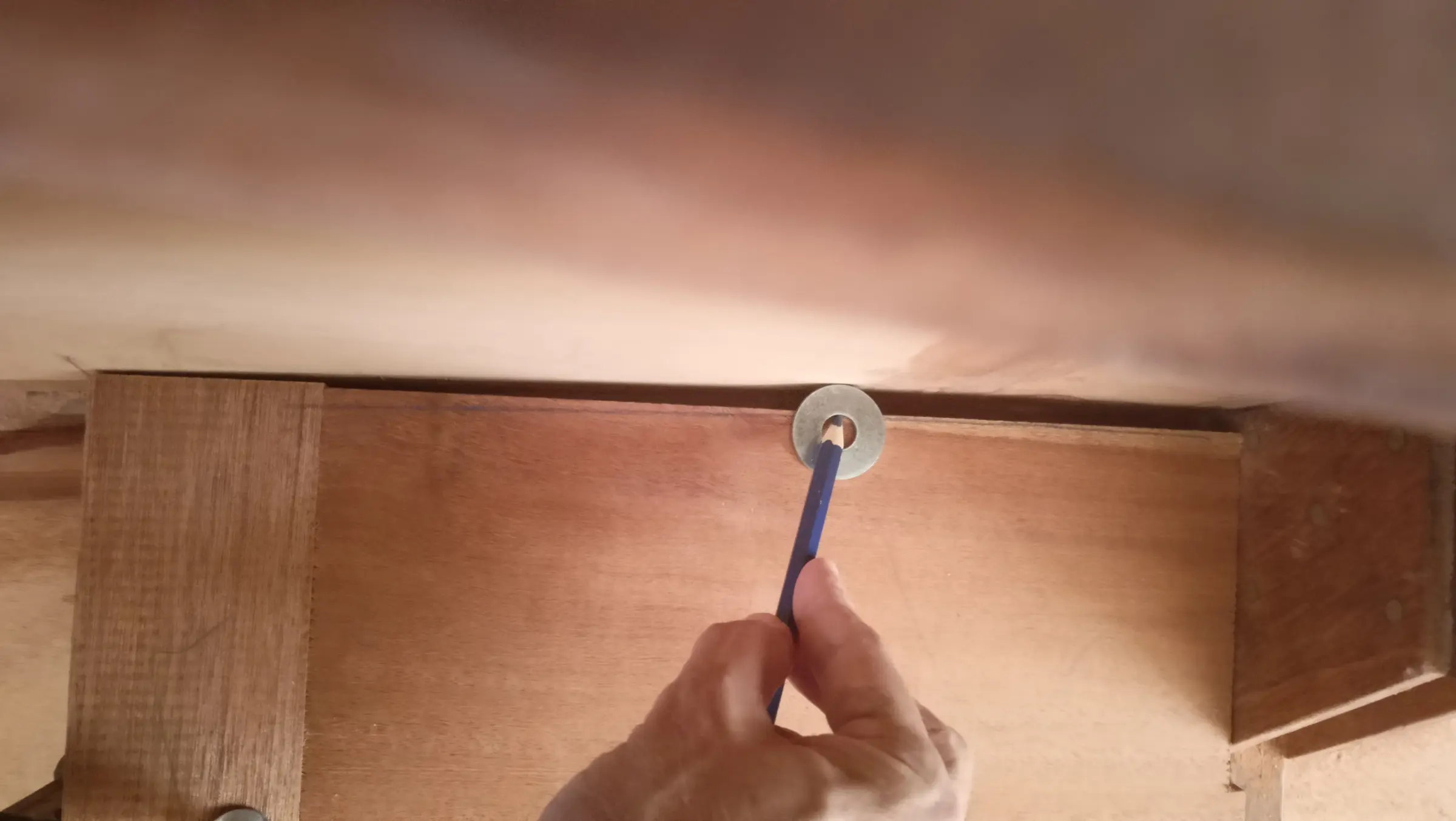
A washer and a pencil were used to copy the curve of the boat accurately.

Then the seat bearers were glued to the bottom of the boat and, at the same time, the seat was given two coats of resin.

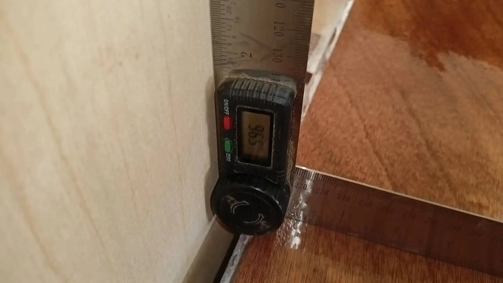
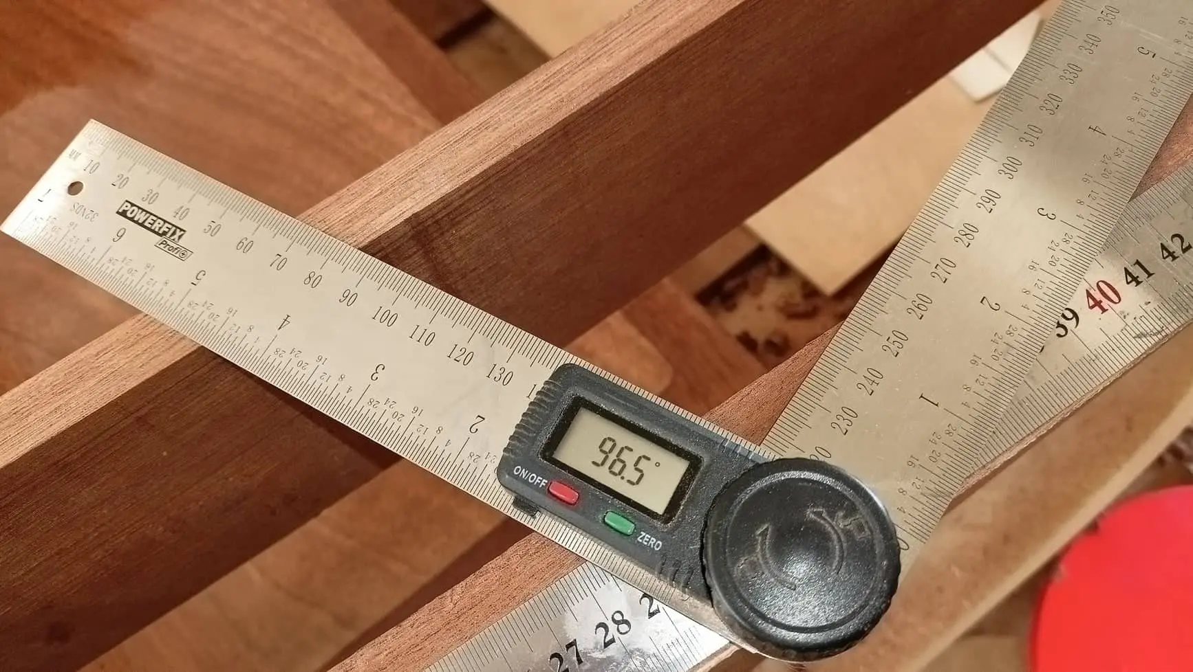
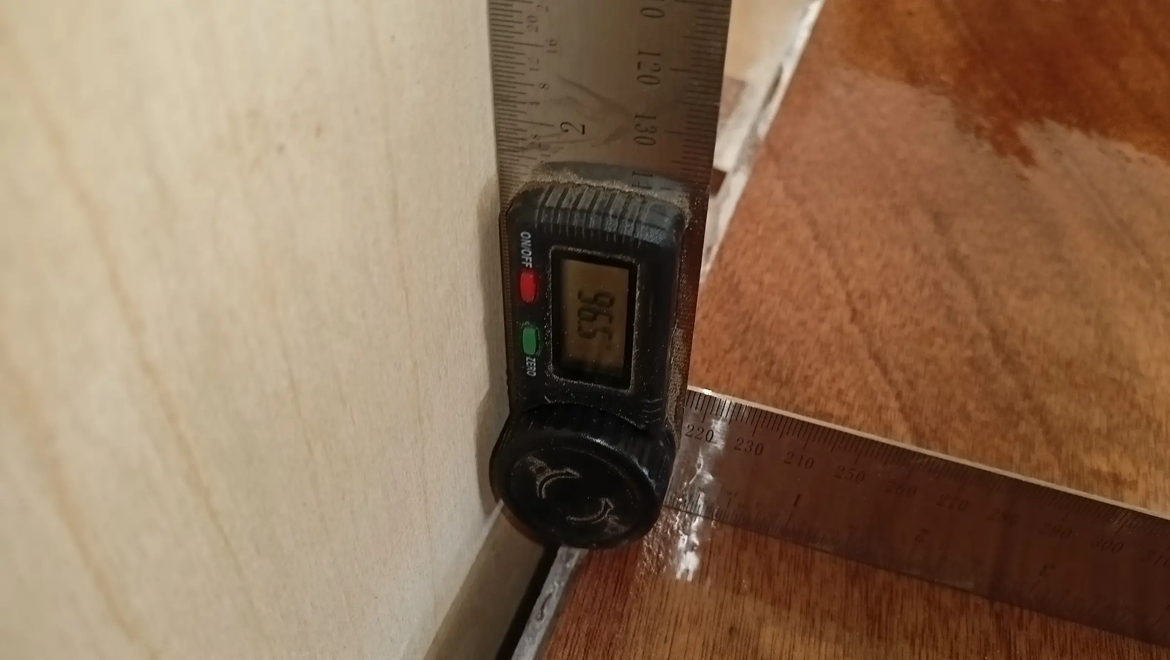
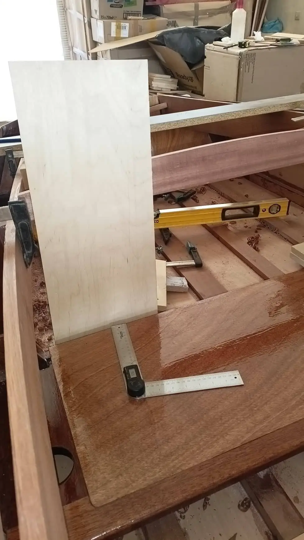
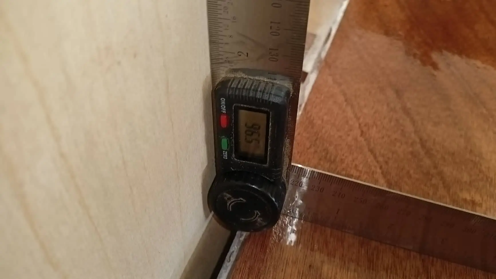
Work started on the seat back and the remaining uprights of the framework aft. The angle between the seat back and the seat will probably be a little over 100 degrees. The 96 shown in the photograph is probably too little. At the same time the sheerline is being shaped all the way round with a hand plane, rasp and sandpaper.

Some photographs below.

Video: https://www.youtube-nocookie.com/embed/5eLQDUcjQwQ


32.5 h

Interior work No. 2

After building the seat I started gluing in the pieces I had prepared for the boat's framework, both forward and aft.

The inside of the boat was given two coats of resin.

Work started on the seat back and the remaining uprights of the framework aft. The angle between the seat back and the seat will probably be a little over 100 degrees. The 96 shown in the photograph is probably too little. At the same time the sheerline is being shaped all the way round with a hand plane, rasp and sandpaper. Some photographs below.


23.5 h

Finishing the hull, and painting (first attempt)

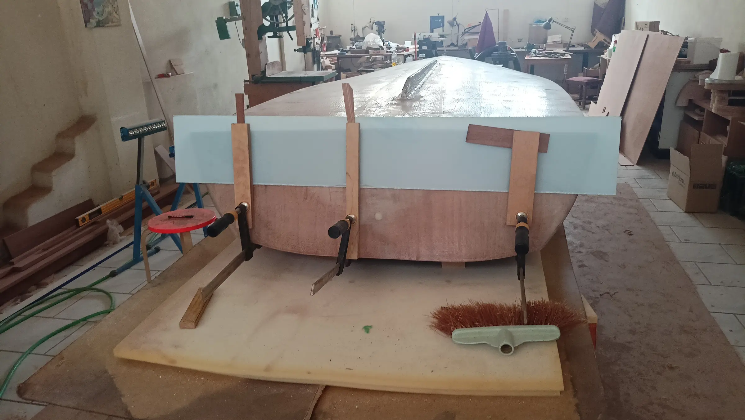
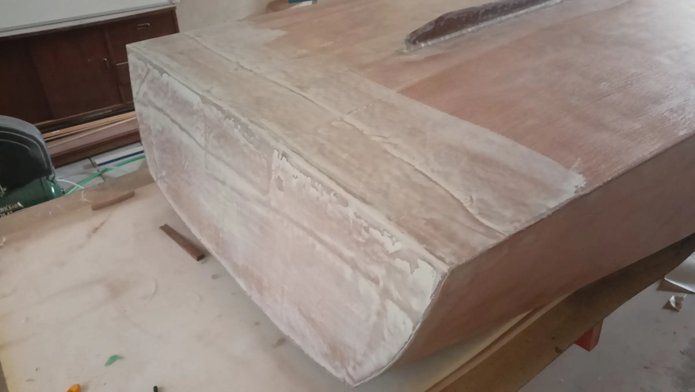
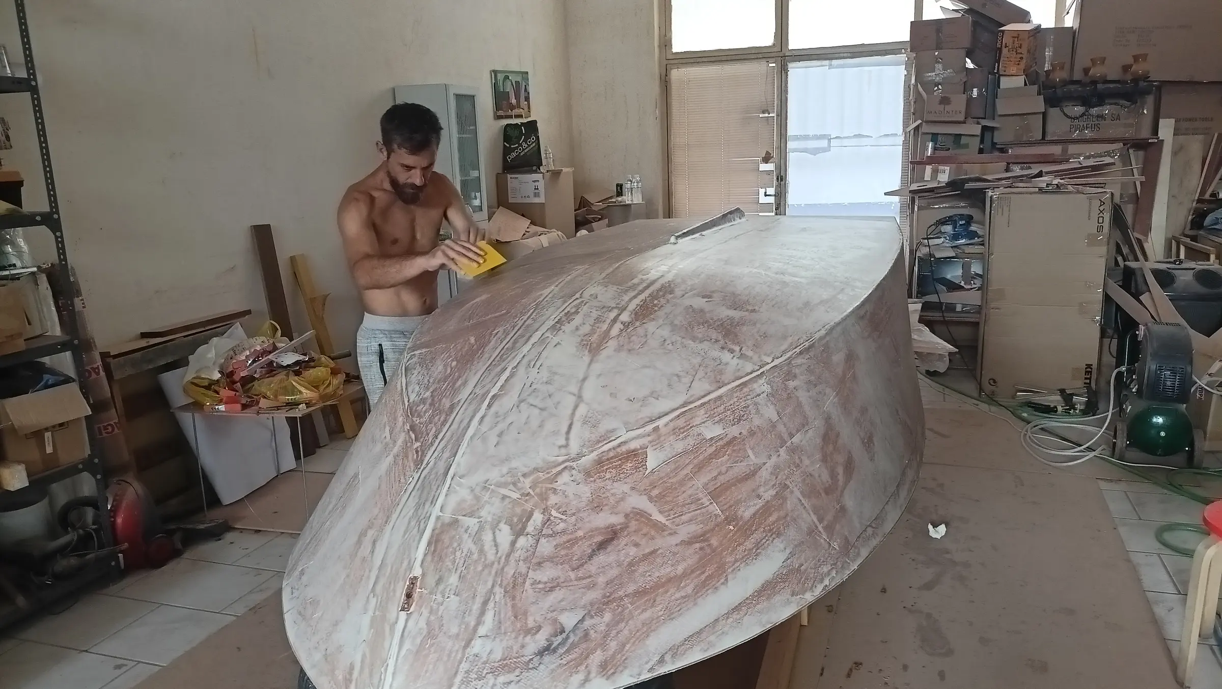
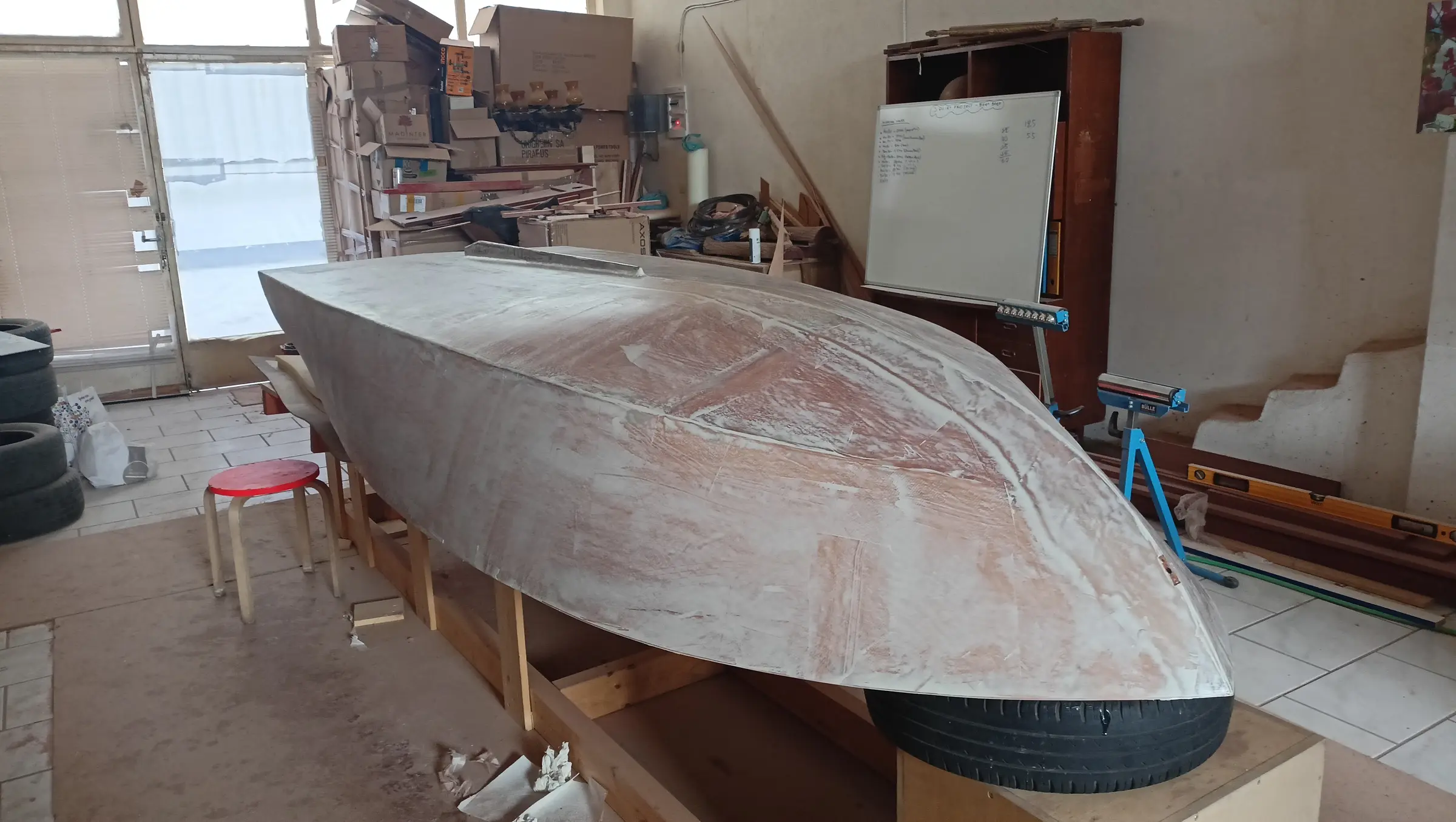
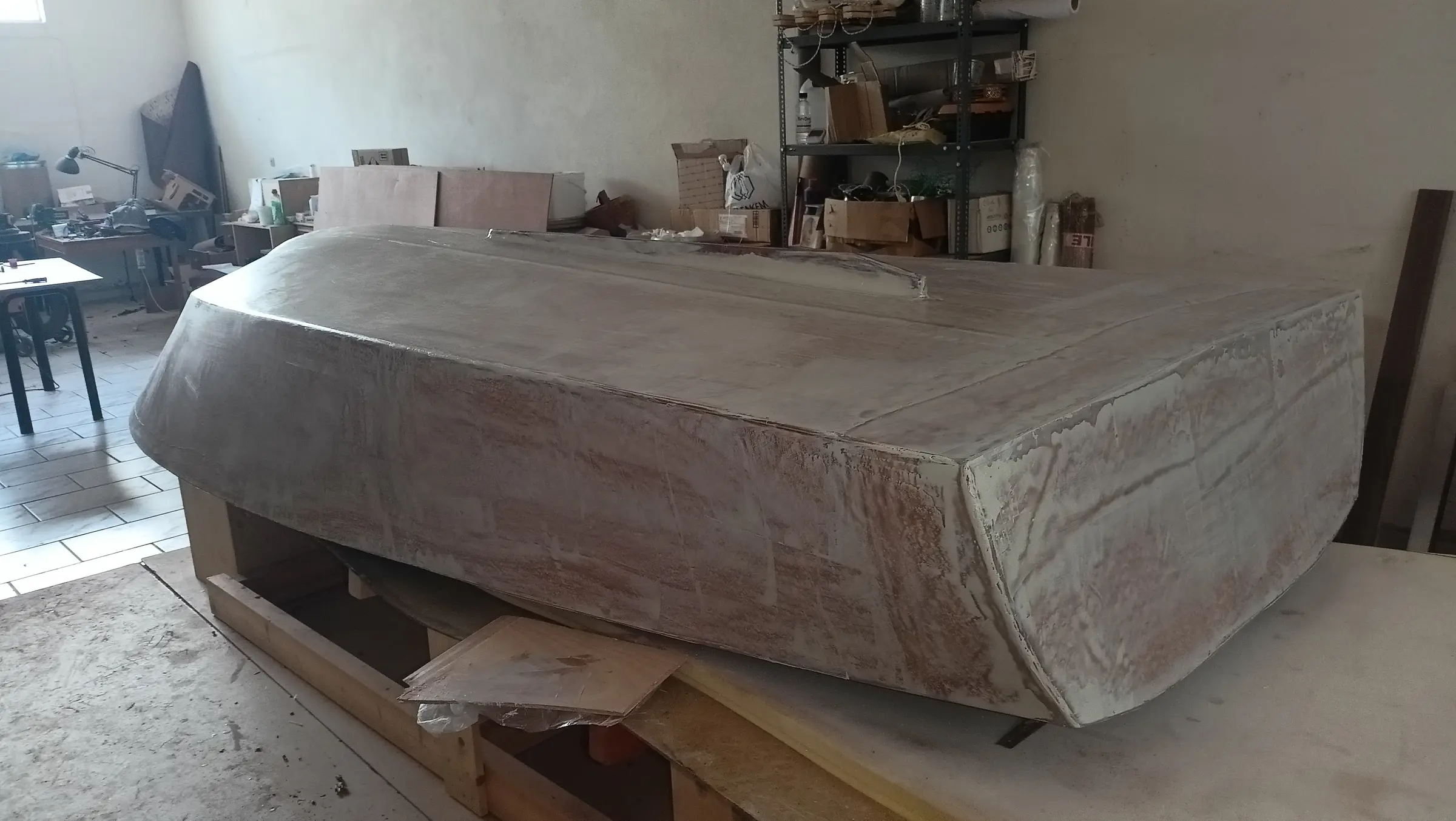
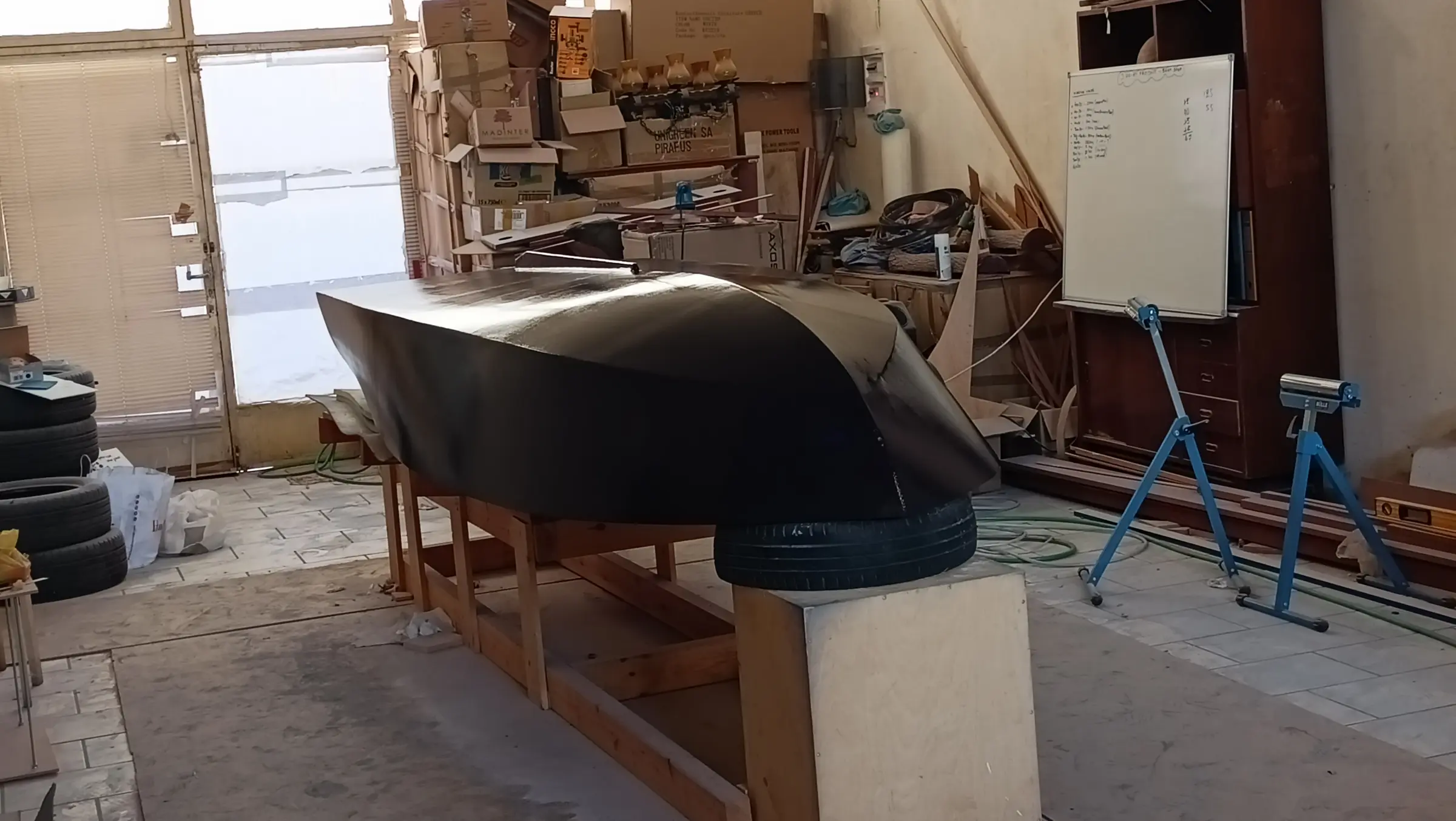
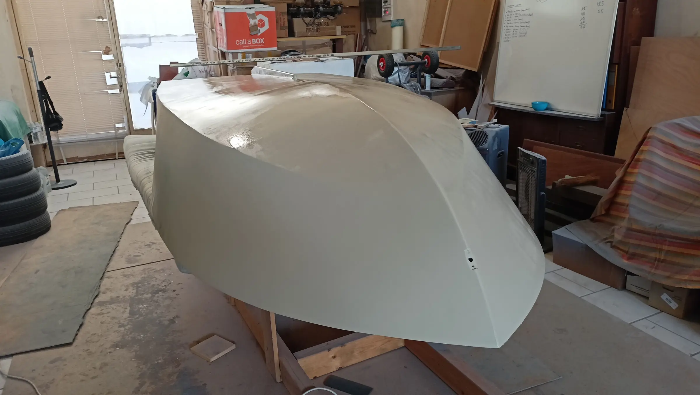
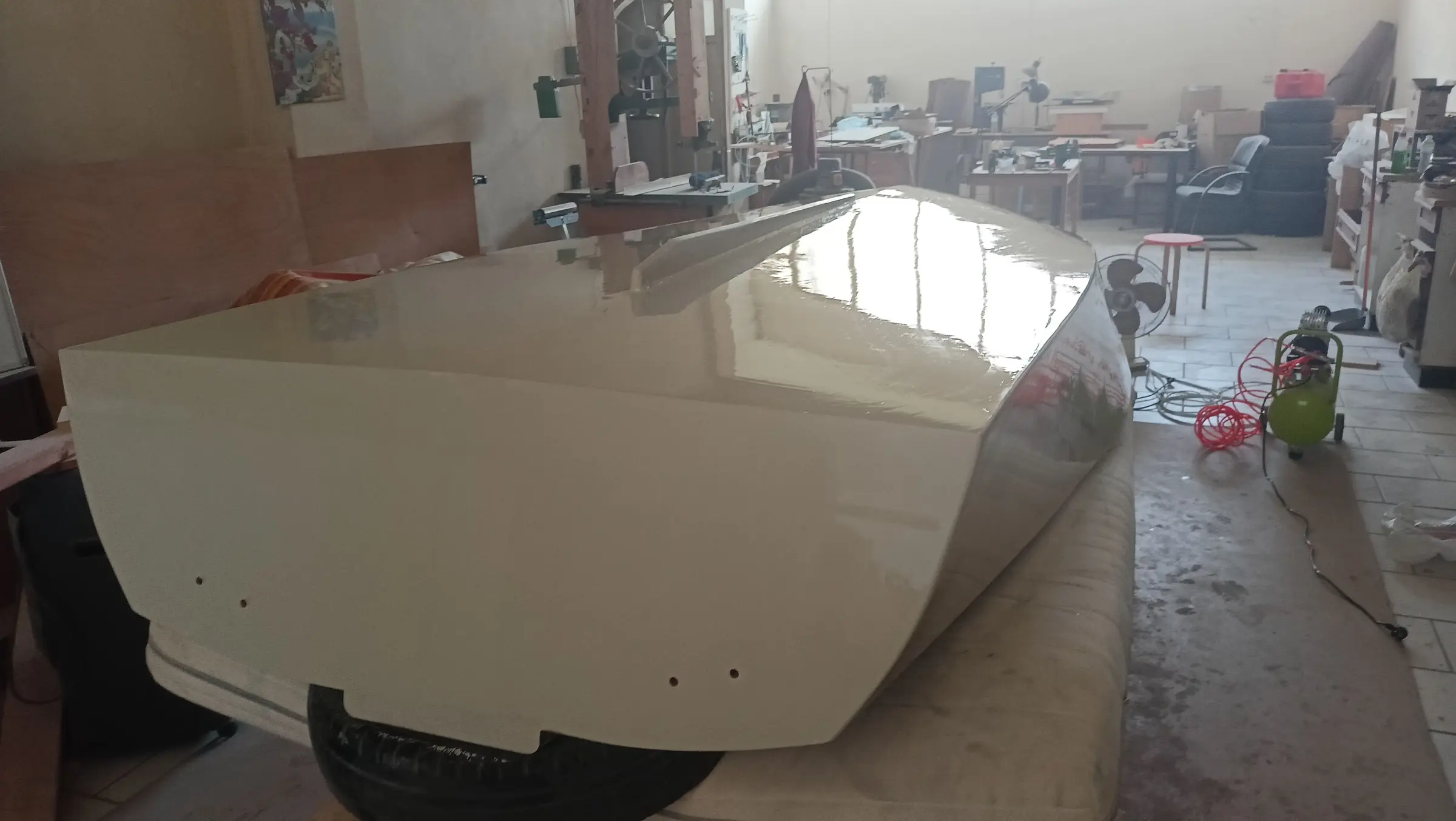
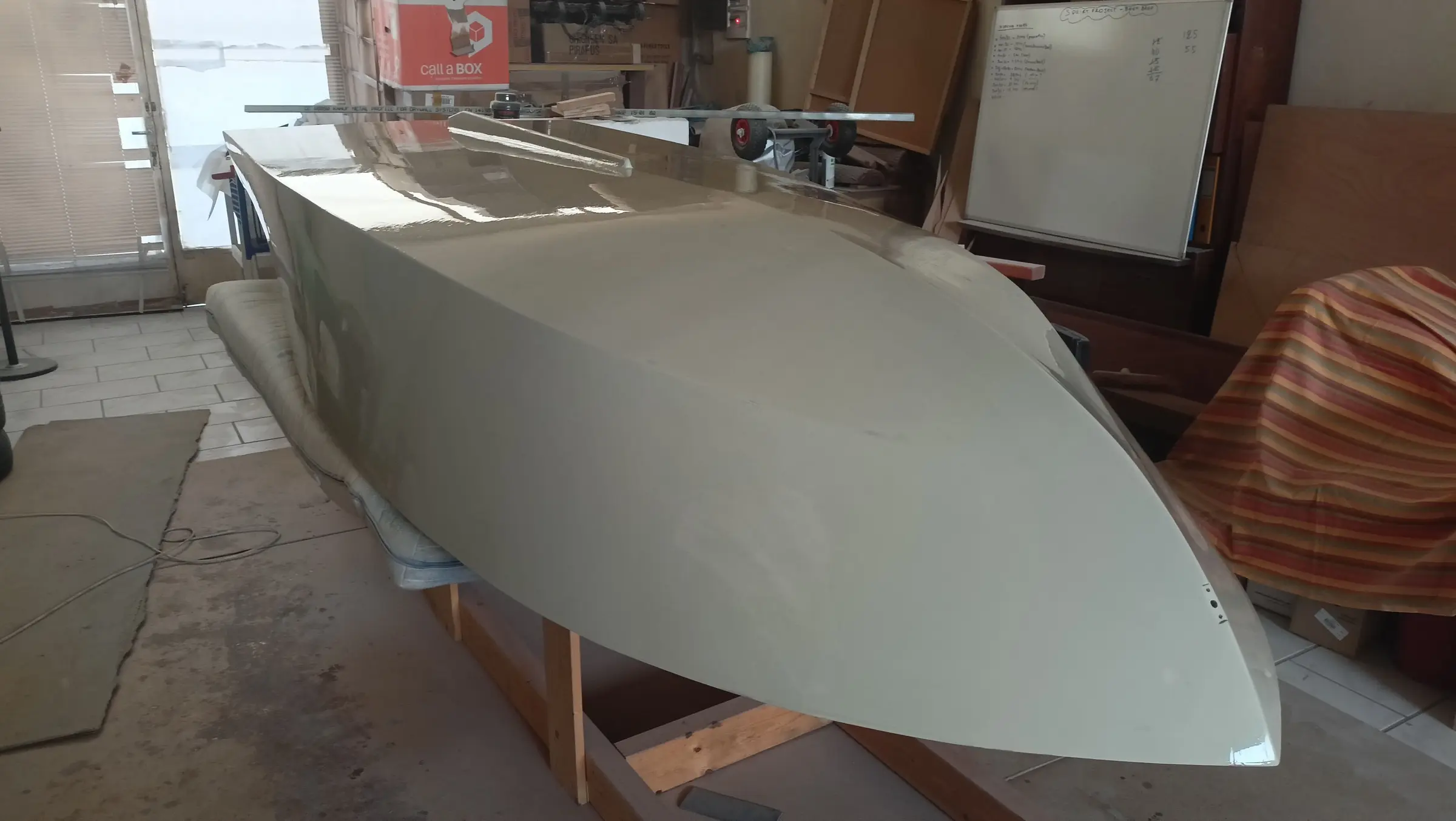
With the shaping finished all the way round the boat, it was time to turn it over again so the work on the hull could be completed. That means four more coats of resin, fitting the skeg, cutting the angle back into the transom to avoid the water cavitating (the joint had been rounded over so the cloth would stick), applying epoxy fairing filler for a perfect finish, then the epoxy primer and the topcoat. Two friends, Yannis and Iraklis, helped turn it over. The boat is still extremely light.

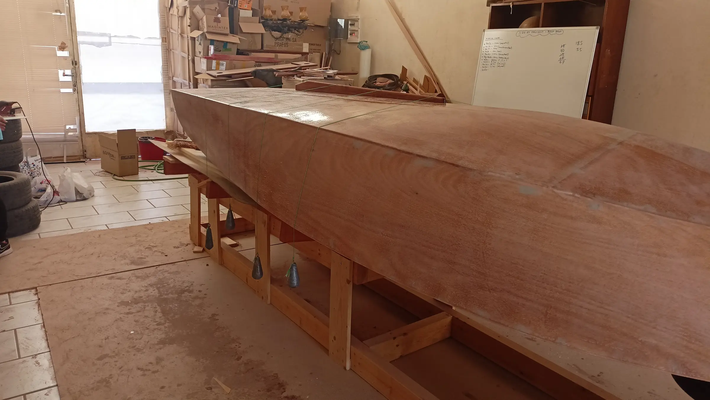
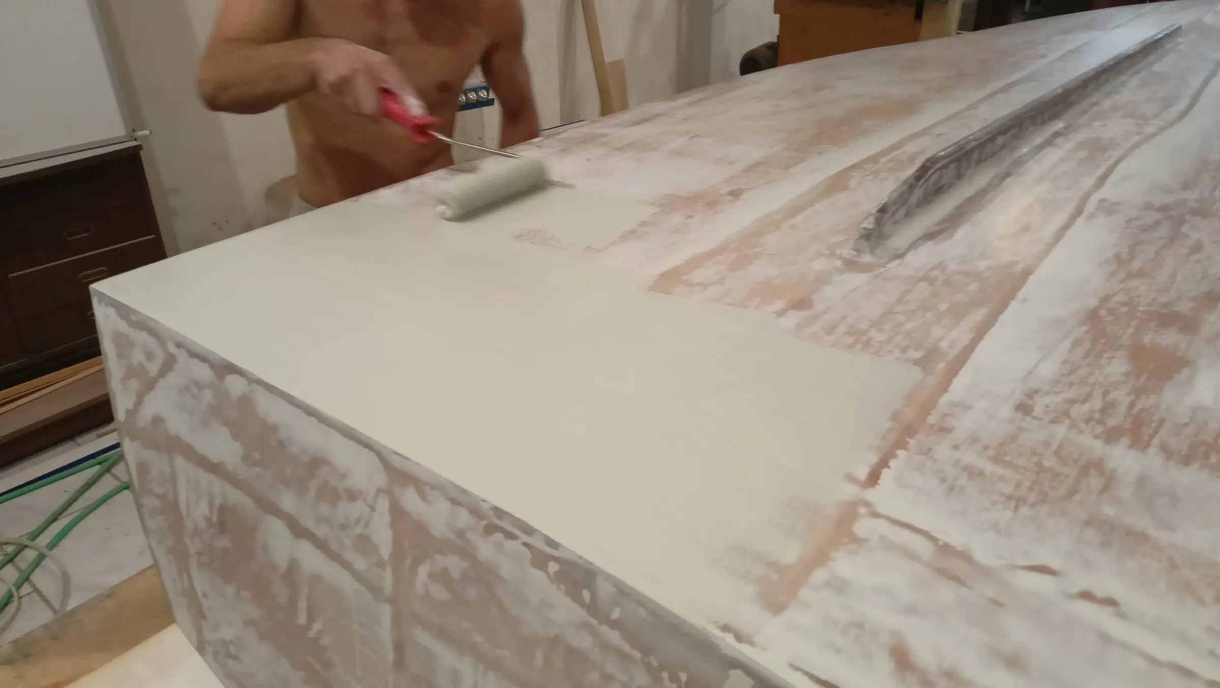
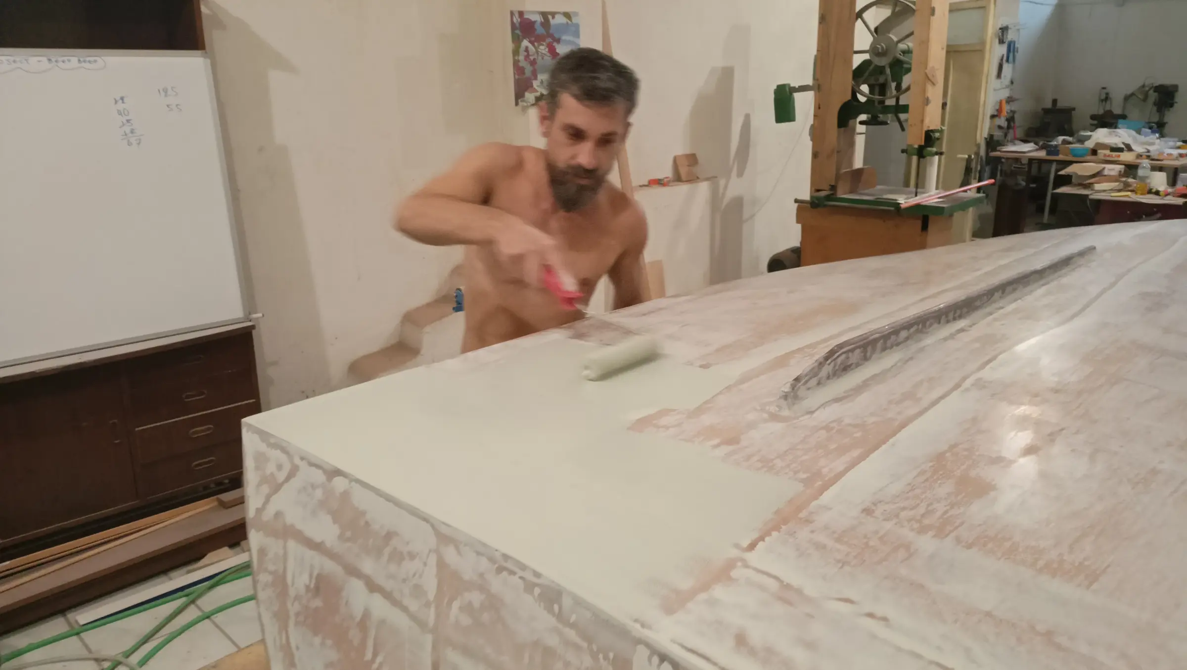
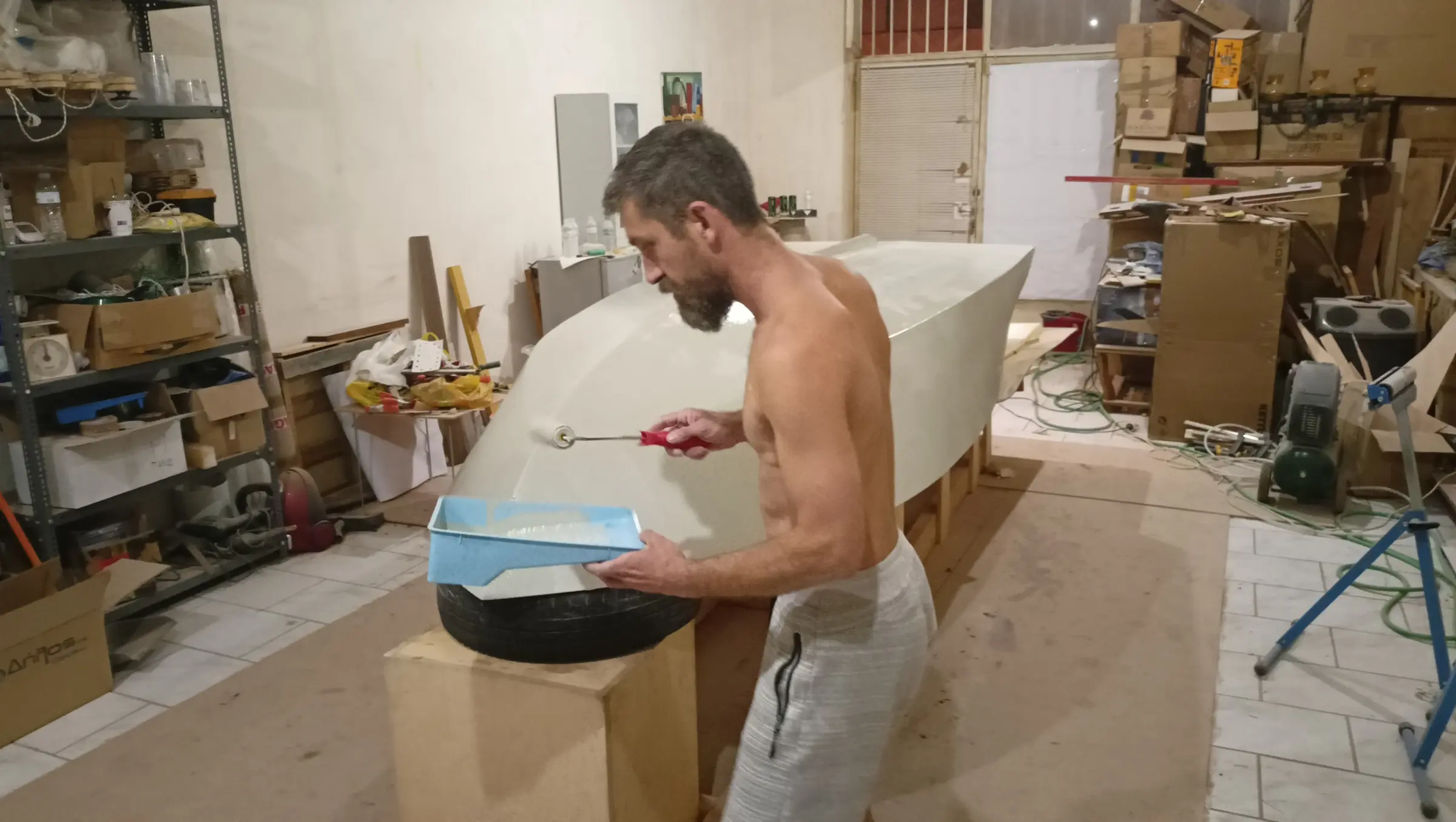
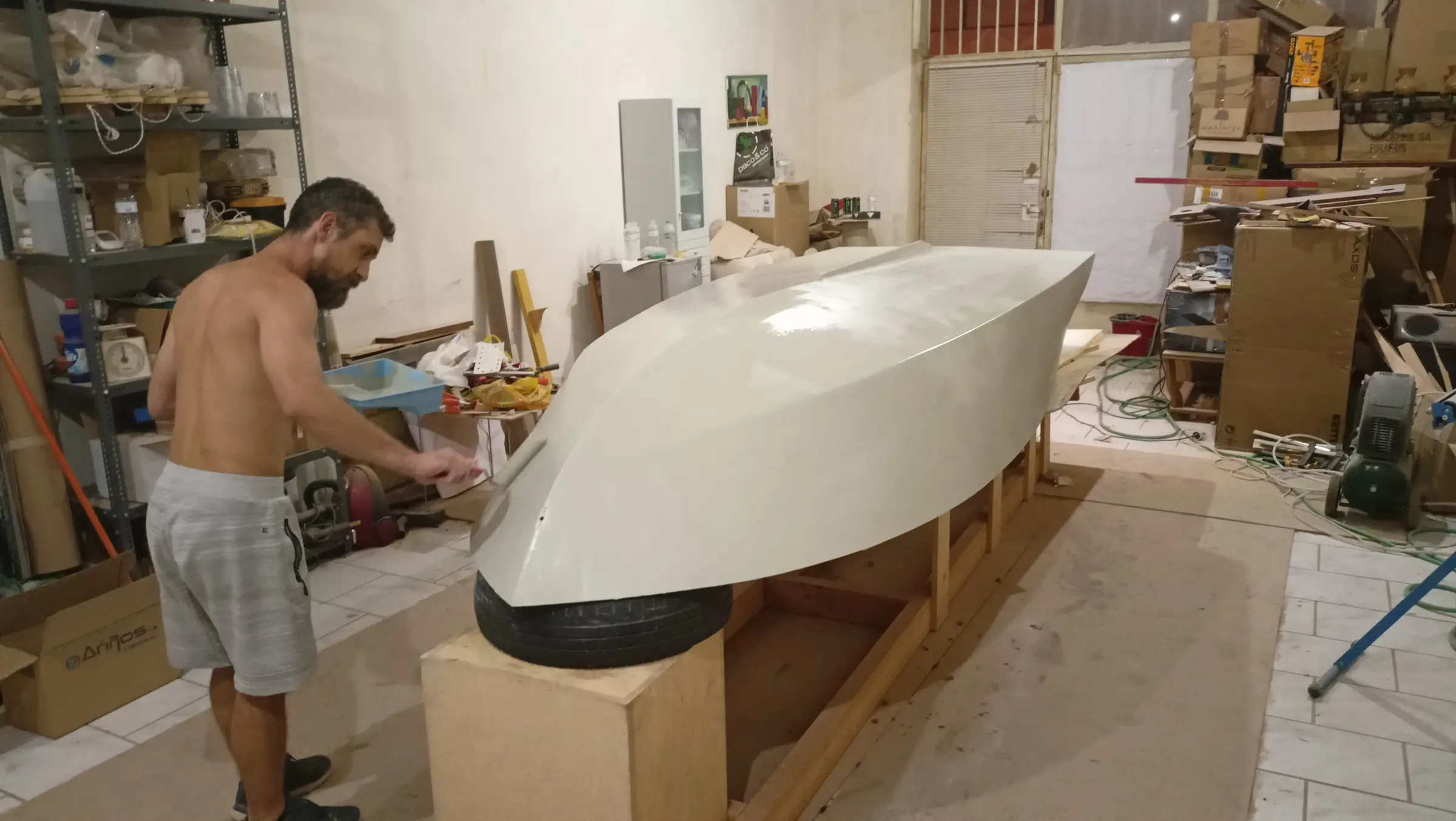
First the boat was cleaned with water and a Scotch-Brite pad to remove the amine blush that forms on the resin, which is water soluble. It was wiped down with kitchen paper. The 4 coats of resin went on in one day, 4 to 5 hours apart. Done that way there is no need to sand, and the bond is chemical as well as mechanical, since the resin has not set. Each coat took 350 grams. The resin was applied with a West System 800 roller. At the end, to help it lay off better and to break the small bubbles that form, I went over it again with the roller but without letting it turn, holding it at the ends and dragging it across the hull. The result that way is much better. Some photographs of the finished result.

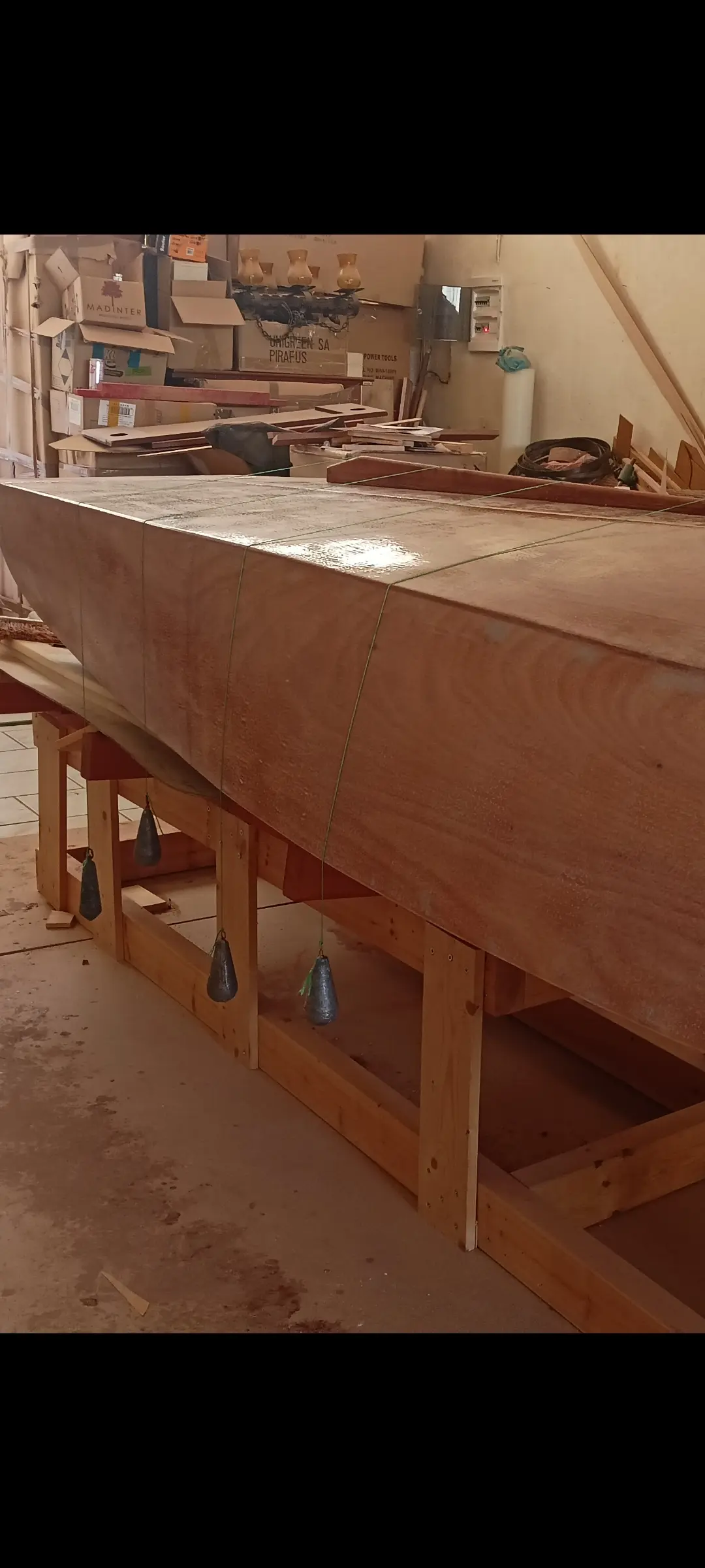
The next job was making and fitting the skeg. I decided to fit one so the boat would answer better to changes of direction. The skeg is 1.20 m long and its aft end is 60 cm from the transom. At the forward end it is about 1.5 cm deep and at the aft end 6 cm, dropping away slightly at the very end. To copy the curve of the hull the skeg was held in the right place and the curve was marked on it using a small block and a marker pen. It was then cut on the bandsaw. It was glued using string and weights to press it lightly against the hull. Some photographs below:

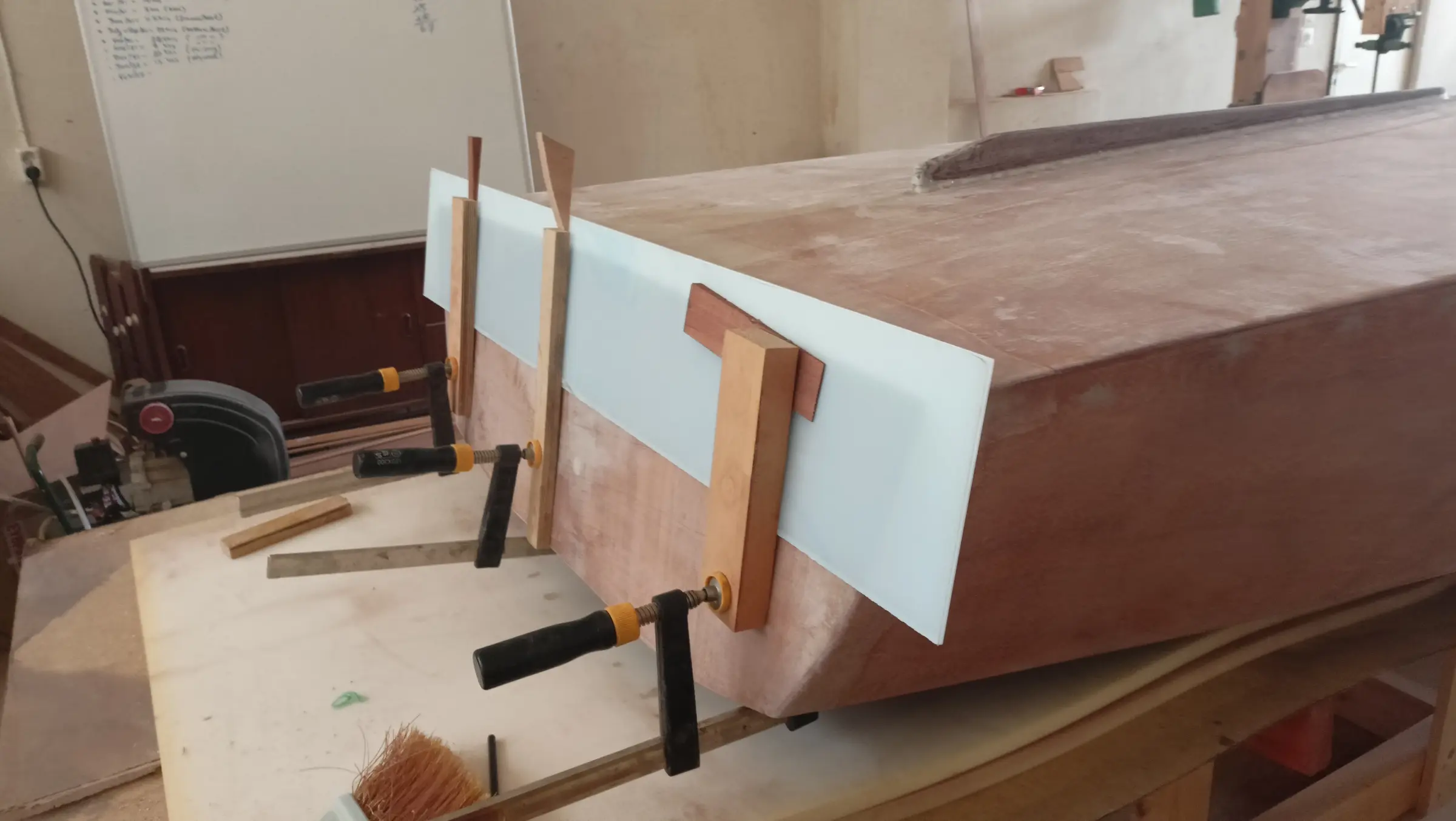
Along with the skeg, the joint between the transom and the hull was reshaped. To lay the cloth, a curved surface had to be created so it would stick down. That curved surface would cause problems though, because of water cavitation. So the angle was cut back in, in the way shown in the photographs below.

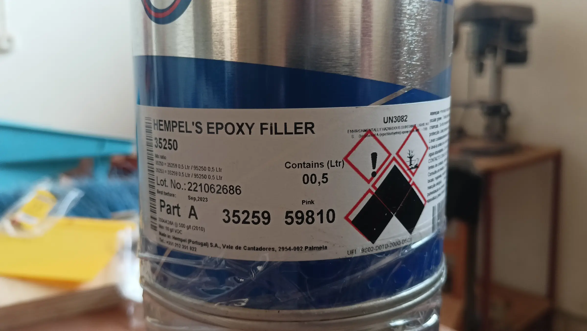
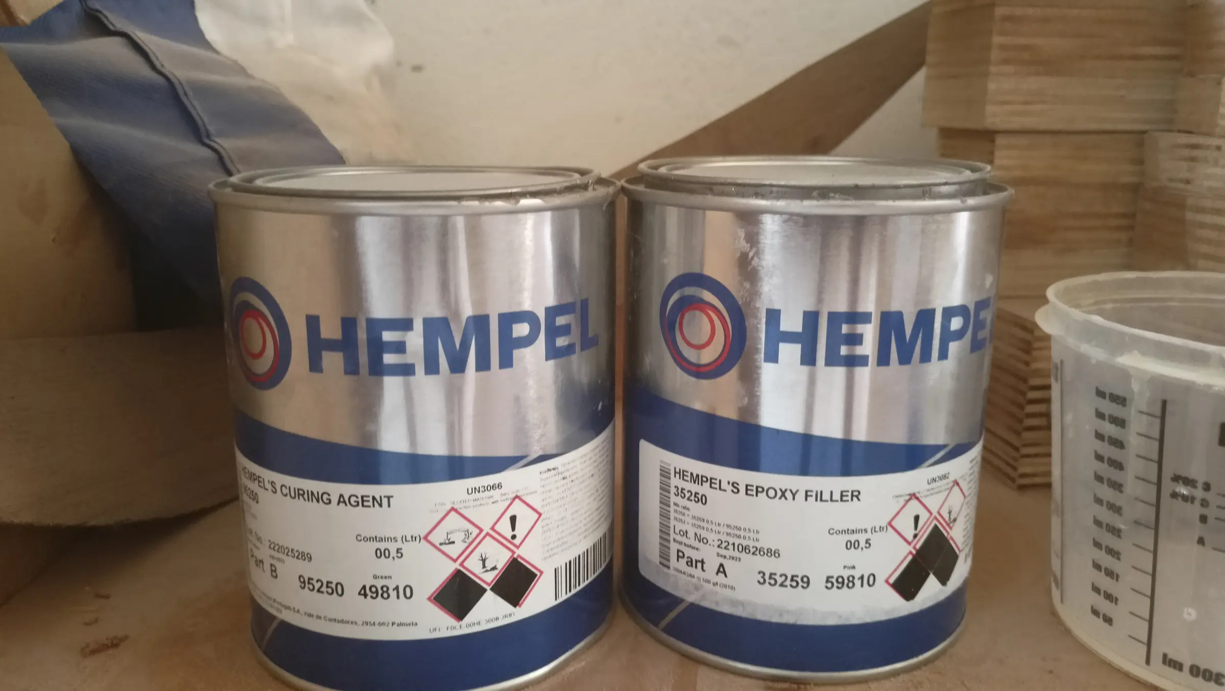
With that work done it was time to skim the whole hull with two-part epoxy fairing filler, to close up the last small imperfections left by the cloth. Perhaps another two or three coats of resin would have taken them out, but I think the filler will certainly make the job easier. If I had chosen to varnish rather than paint the sides of the boat, three coats of resin would have been the only option. I started at the transom, which has the worst of it and is a relatively small area, so I could do my testing there.

Two coats of filler went on, since after the first coat and sanding a few imperfections were left. After the second coat it was sanded again, paying a lot of attention to the details.

The hull was then washed with water and, once dry, cleaned with the thinner made for the epoxy primer. The whole 750 ml tin was used for the first coat of primer. Two percent thinner was added to the mix. Room temperature 26.5 degrees Celsius. Humidity 50%. Mohair roller.

Some photographs of the process, again with my friend Stratos, and the finished result:

The primer instructions say you have to wait 48 hours before sanding the surface. That presumably applies at lower temperatures, but I stuck to it. The whole surface was sanded with 240 grit and the second coat went on.

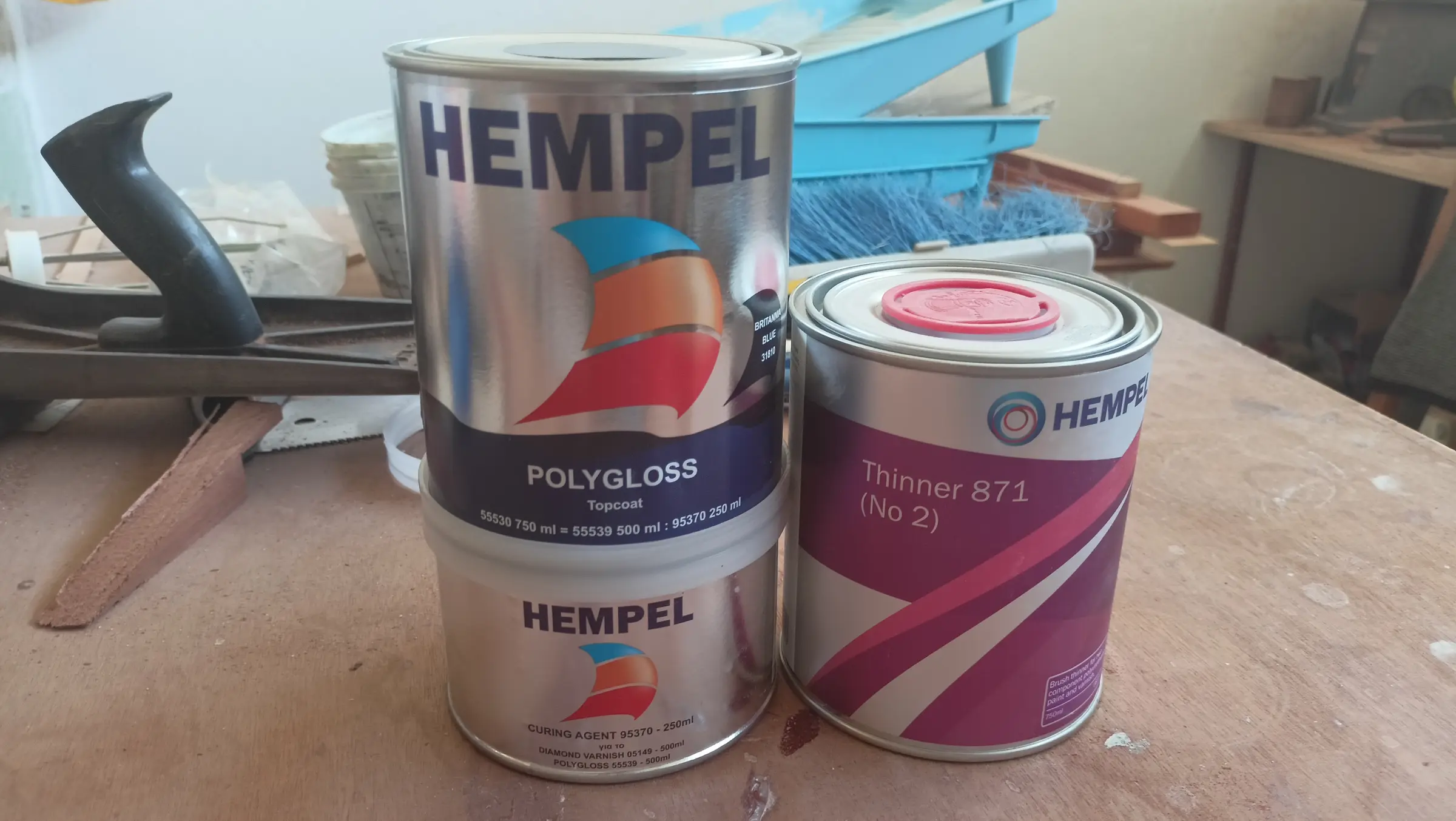
The primer was sanded again, this time with 320 grit, and the surface was prepared for the topcoat (washed with water and with the paint thinner). The colour is Epifanes Britannia Blue and it will go on with a polyurethane foam roller and then a brush (the roll and tip method). After rolling it on you go over it with very light strokes of a dry brush, and the result is much better. The video below shows the method.

The result after the first coat is shown below.

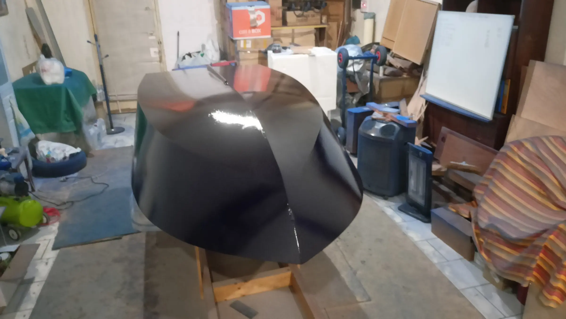
The result is utterly disappointing. Close up you can see a lot of bubbles that have formed in the surface. That may be down to how very hot the workshop was over the summer. Or perhaps that was not it at all and I did not have the thinning right. Whatever the cause, I hope to find out over the winter. I have decided to stop bothering with the painting. I will turn the boat over again and carry on with the work on the inside.

The materials used were:

Video: https://www.youtube-nocookie.com/embed/k-SGcSlNmoo


8.5 h

Interior work No. 3

The boat has been turned over again. It was set down temporarily on car tyres, because to go back on the base that has to be modified now that the skeg is on. I will make it at some point and move the boat as soon as I can find company. Work can be done quite comfortably on the tyres anyway. It sits a little lower (I have used two tyres so it comes up a bit more) but the work goes reasonably comfortably.

The jobs to be done are gluing in the seat back and the timbers aft that will form the locker and the engine cutout. The uprights behind the seat back were cut, along with the last one before the cutout. That last one will not be glued until the engine is fitted, so I can see where it goes.

Some photographs below.

The next job was a second coat of resin inside. To do that, everywhere the first coat had gone had to be sanded. The resin will only go on the areas that will not be seen. The areas that will be seen will get the 207 hardener, which gives a far better looking result and has better UV protection. Obviously it needs varnishing afterwards as well.

The sanding was fairly punishing work...

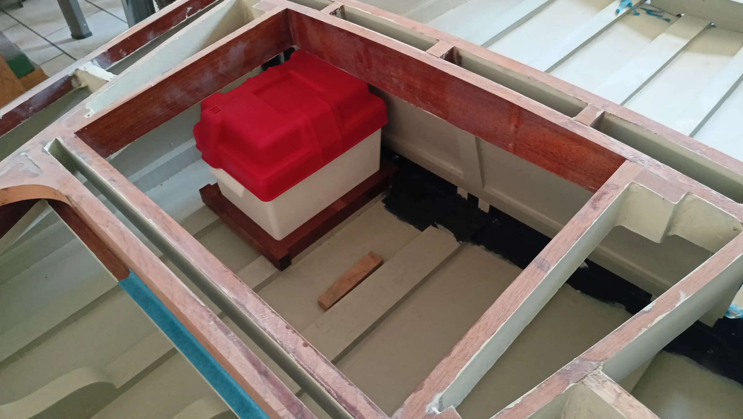
Another dilemma I have to settle is where the fuel tank and the battery will go. The problem is mainly their weight. If they go aft it increases the weight at the back of the boat and, combined with the heavy outboard, there may be a problem. If they go forward there will probably be a problem with vibration, and a new supply cable will definitely be needed (obviously a negligible problem).

After a lot of thought and asking other builders I decided to put it aft, but as close as possible to the seat back and away from the transom. The battery problem turns out not to be a problem, because the outboard does not need many cranking amps (CCA) to start. I found I can buy a lithium battery weighing about a kilo.

To glue the seat back in, I had to prime and paint the areas I would not be able to get to afterwards. They got two coats each.

The back was then glued in, after adjusting the height of the blocks it sits on slightly so it came to the right height.

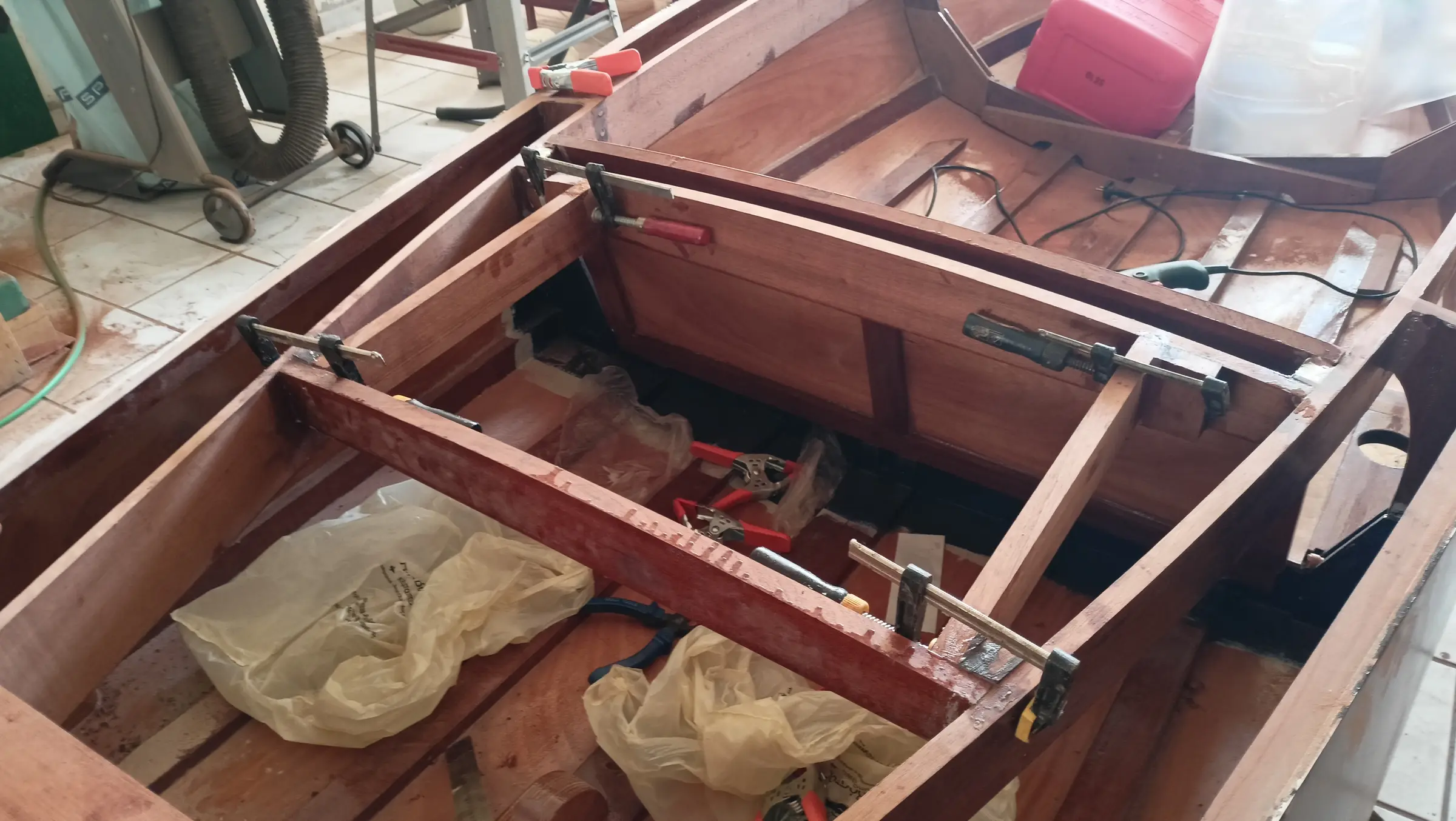
The next job is gluing in the last timbers that will form the locker and the engine cutout. To decide the size of the cutout I would like to fit the engine, so as not to get any unpleasant surprises. Visually I think that if I split the locker and the cutout evenly it will look best.

The blocks that will reinforce the aft face of the locker were glued in, and then that piece itself, with the same curve as the other uprights.

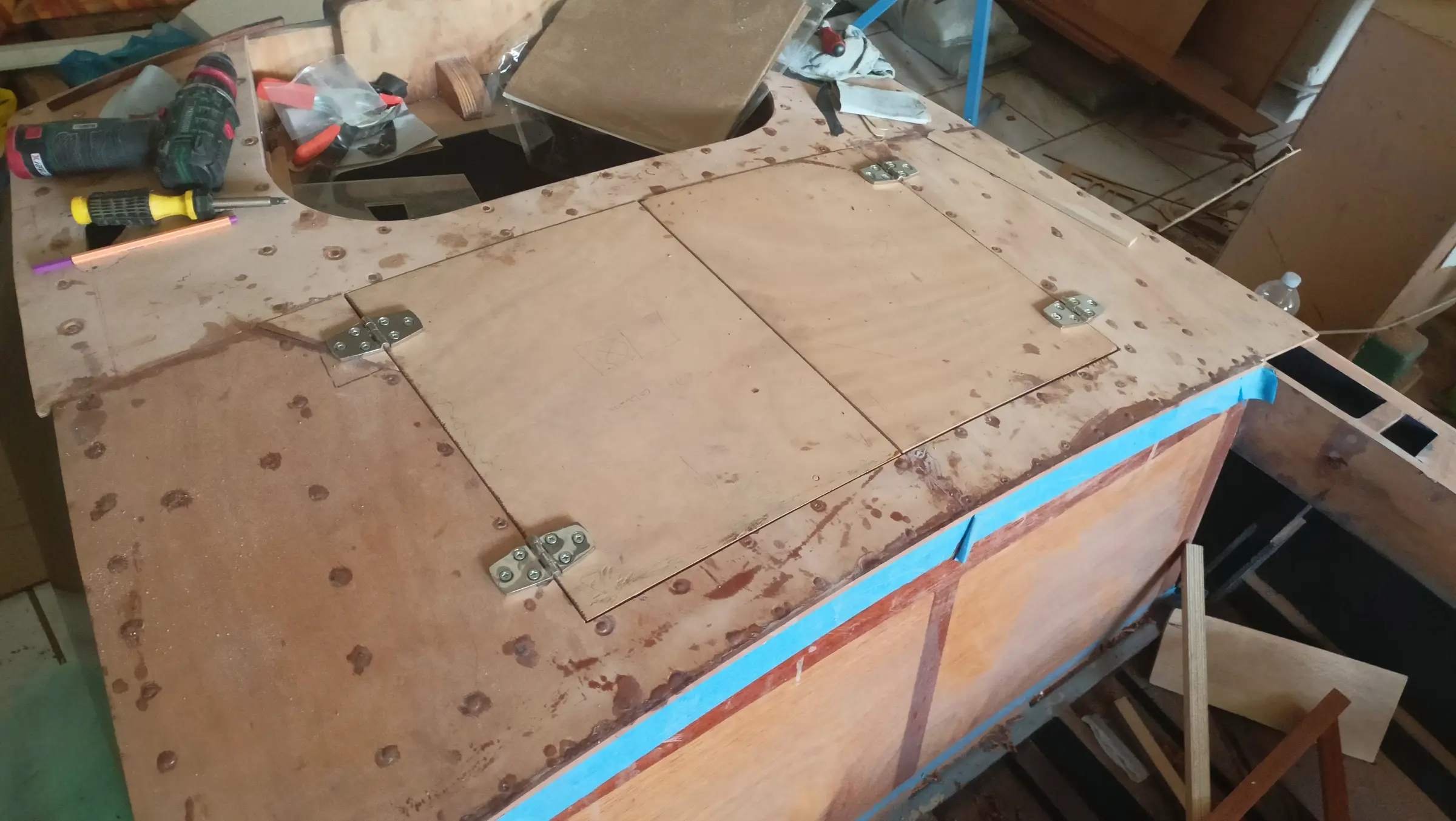
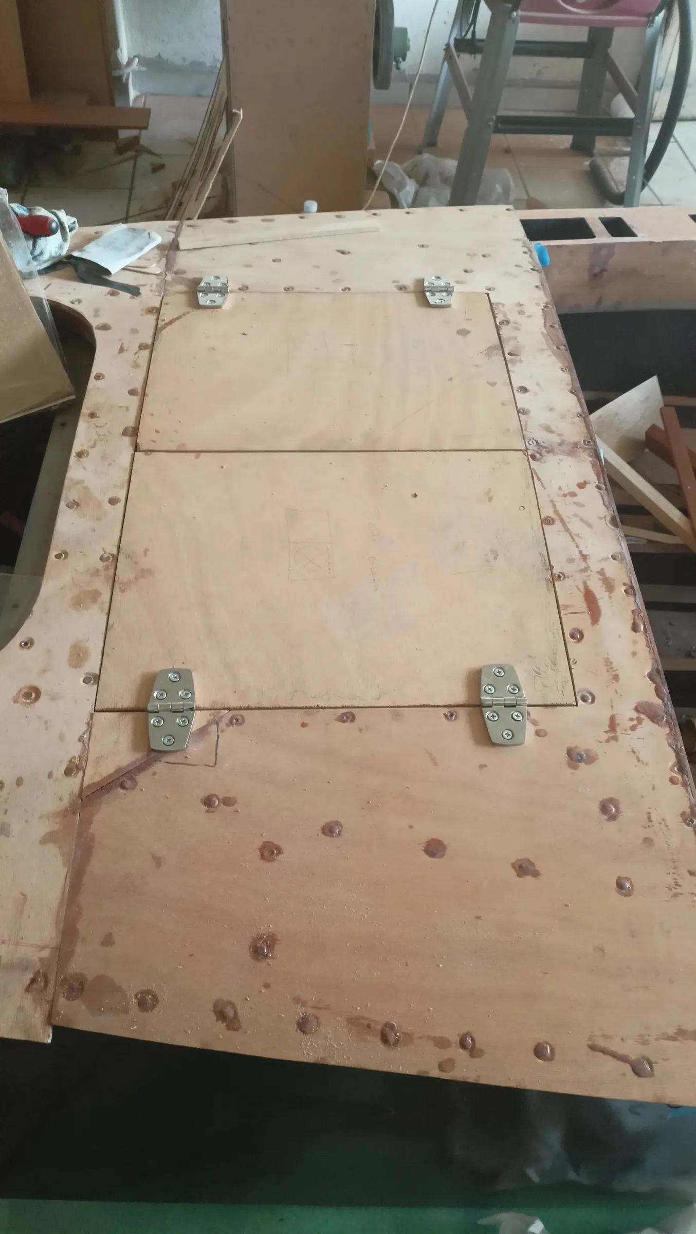
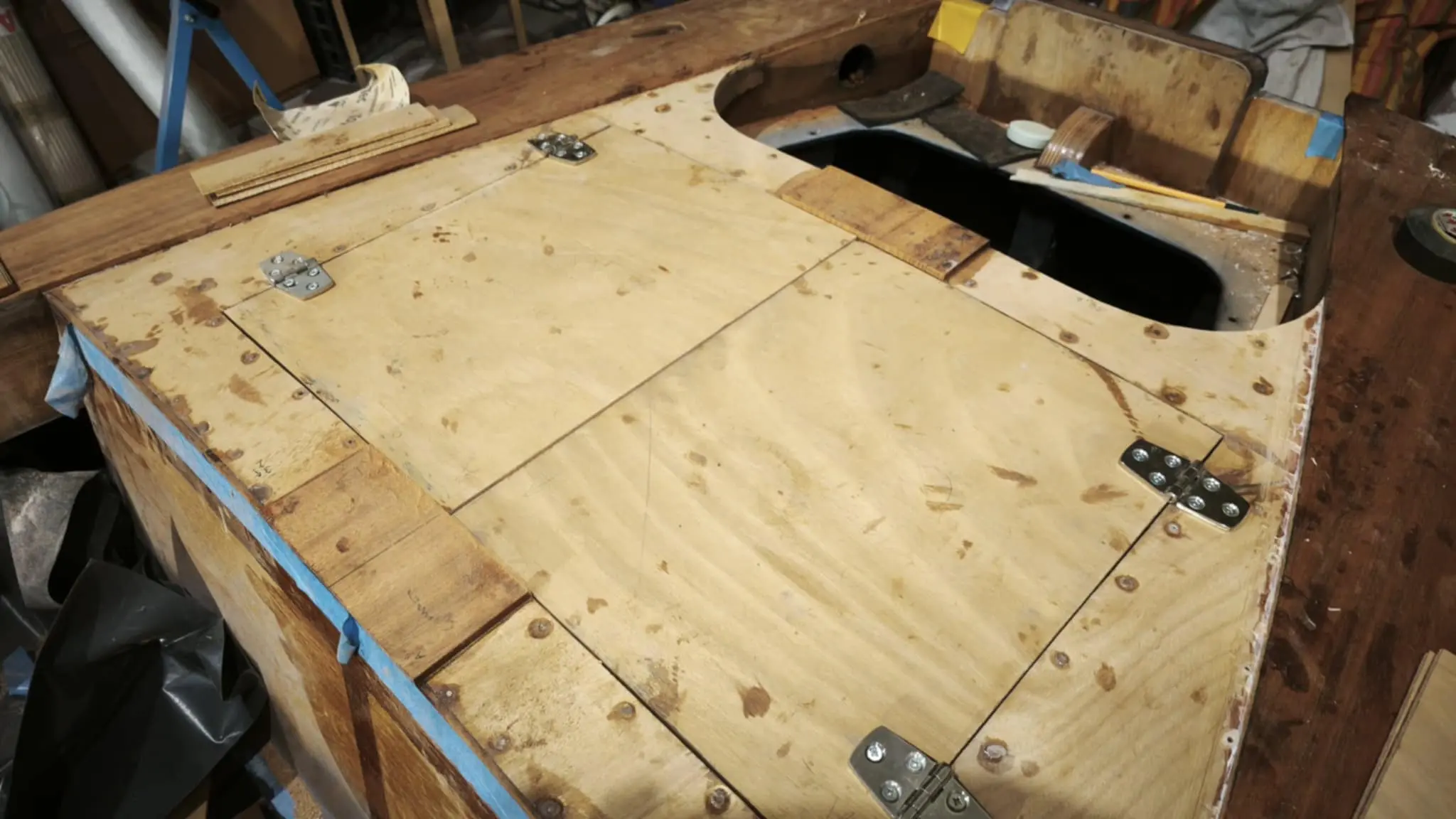
All the remaining pieces were then cut. Both the ones that will form the locker opening and the locker lid itself.

The photograph below shows the arrangement of the locker timbers. The two middle pieces are two because I have not yet decided how the locker will open.

I have two options:

What bothers me about the lid opening backwards is access to the engine. I have chosen (because of weight) an engine without power tilt, so I have to be able to tilt it by hand. The lid might be a serious obstacle. What kind of locker it will be will be decided once the engine is on the transom. Look at the photographs below for two different lockers and the access to the stern, from their owners.

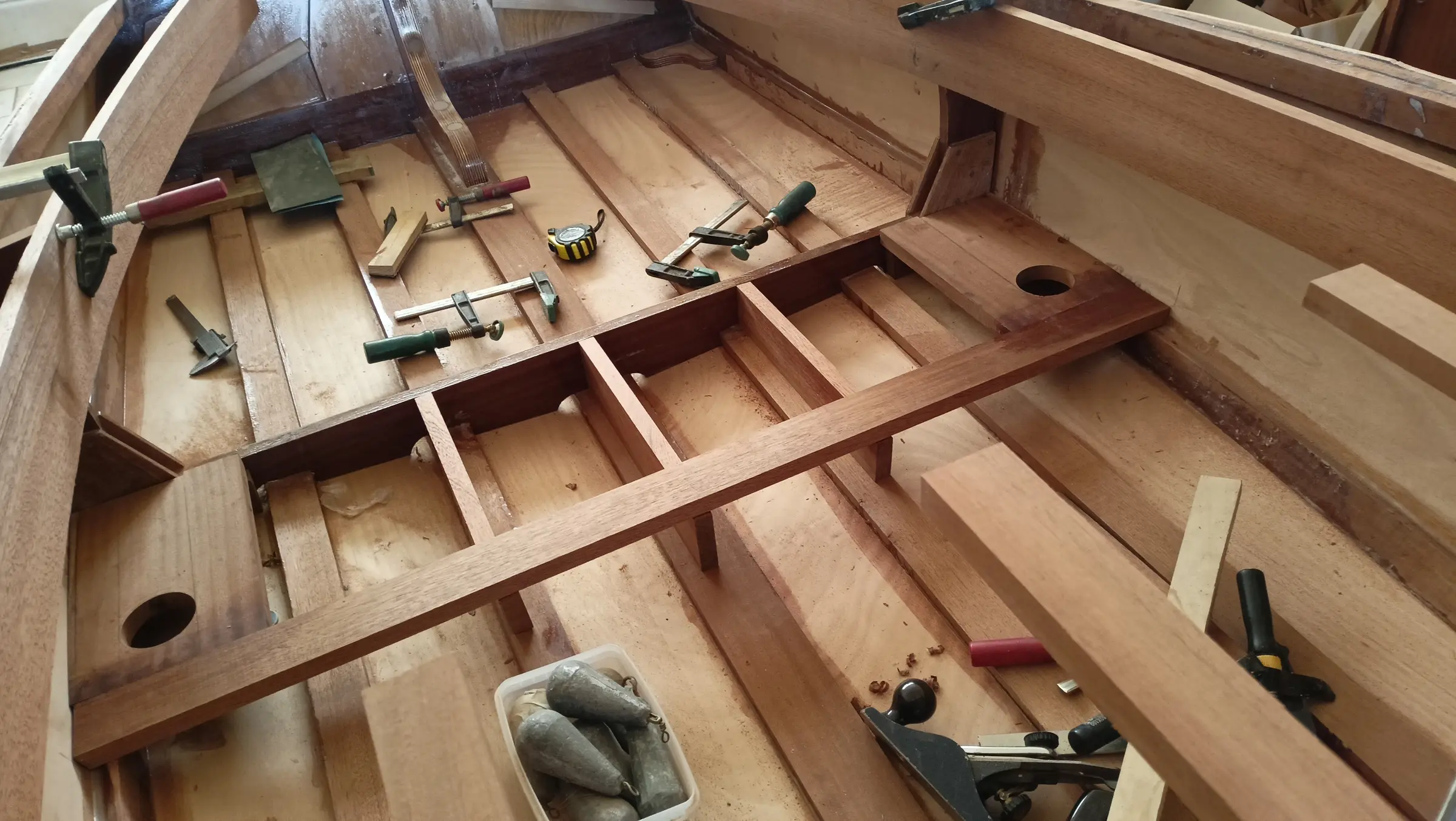
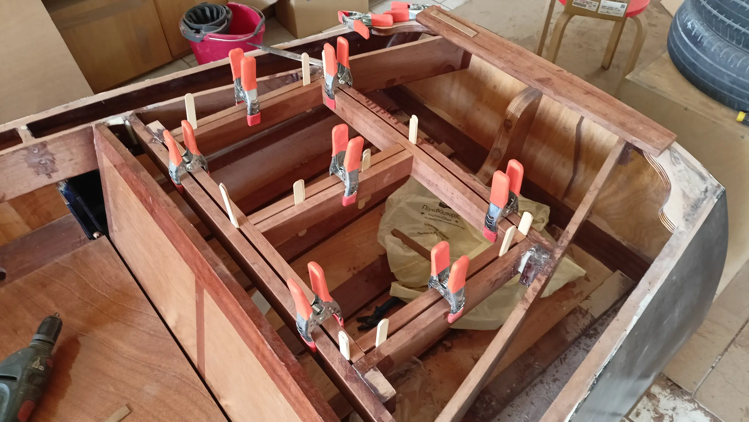
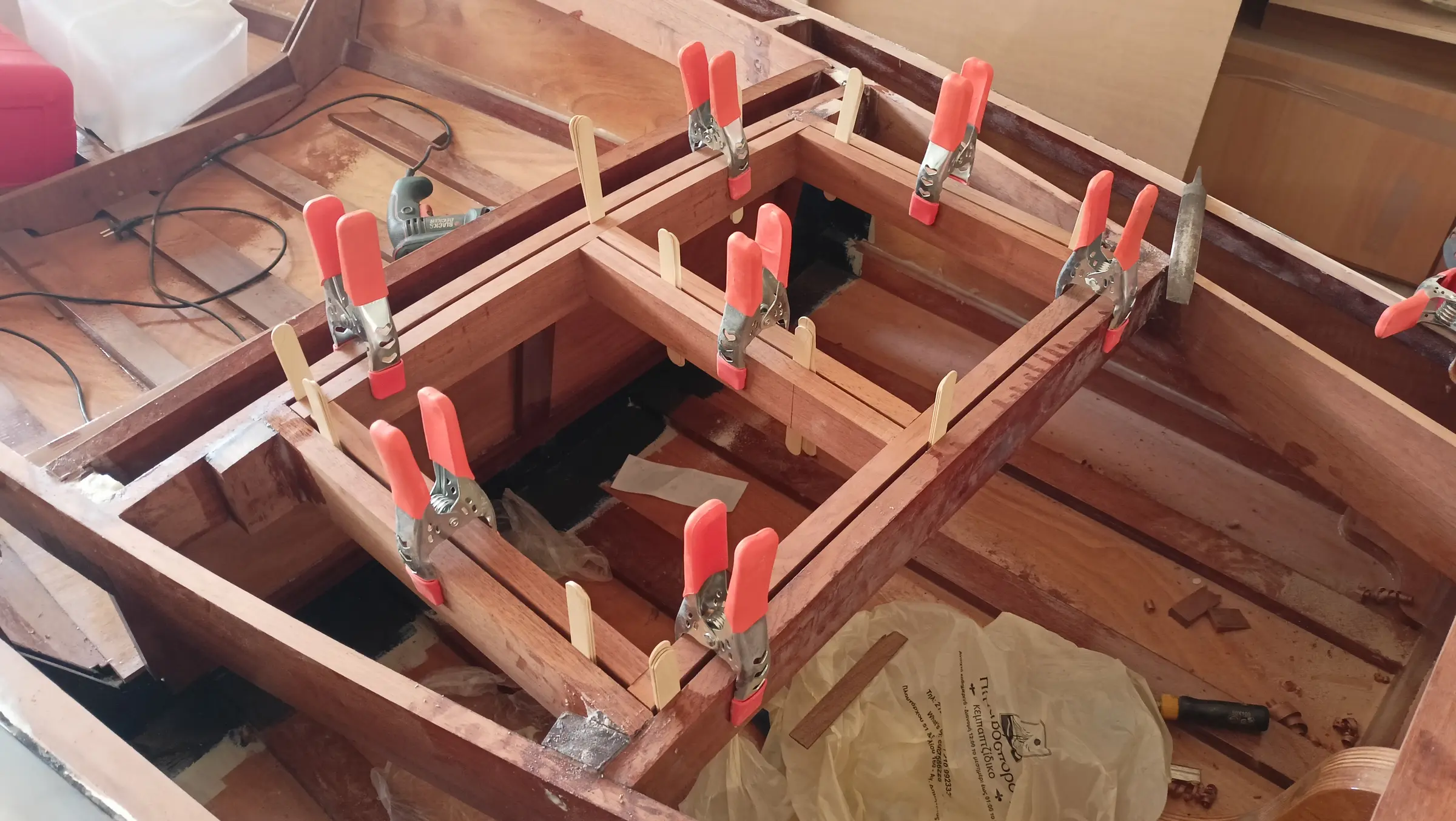
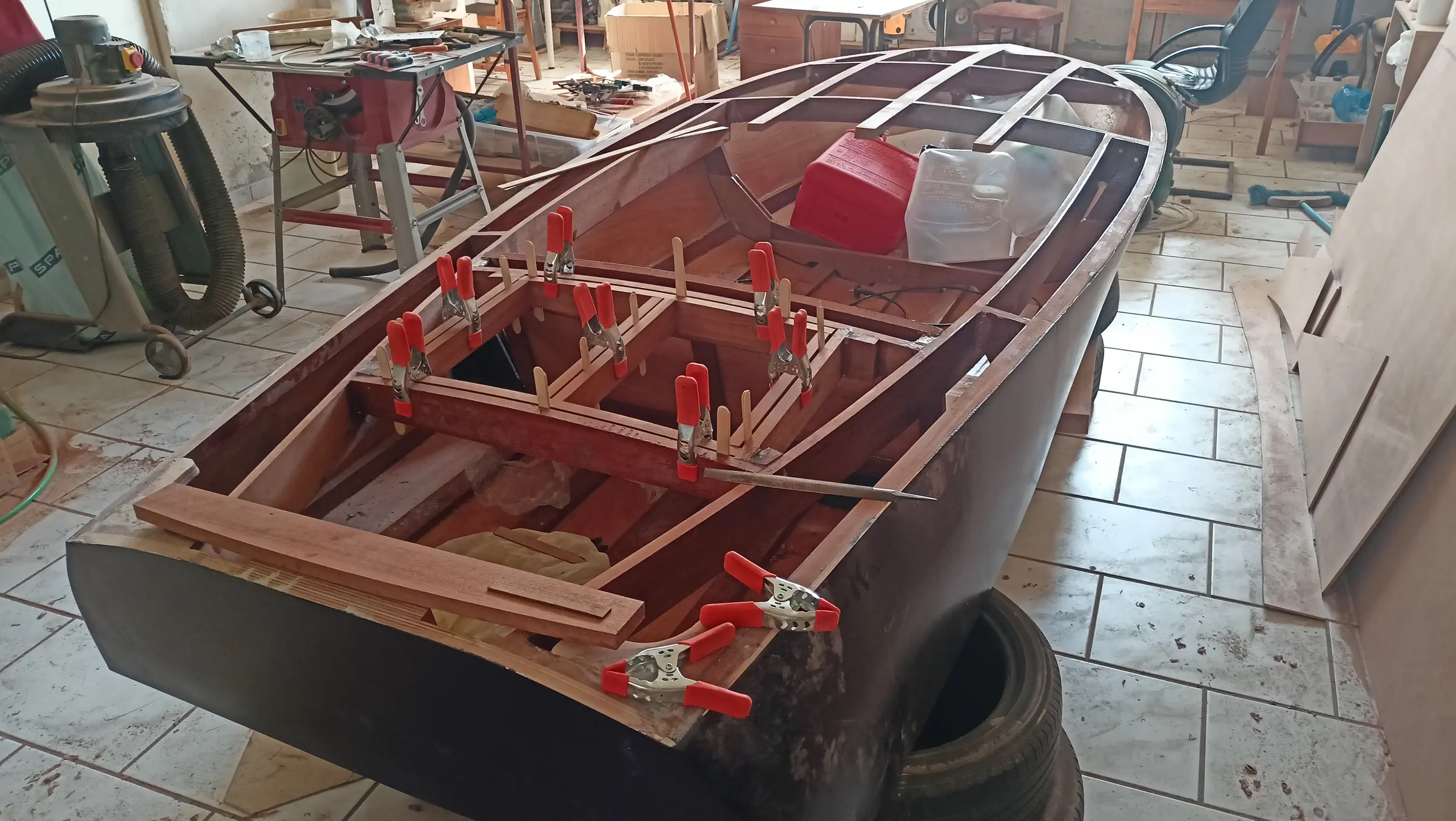
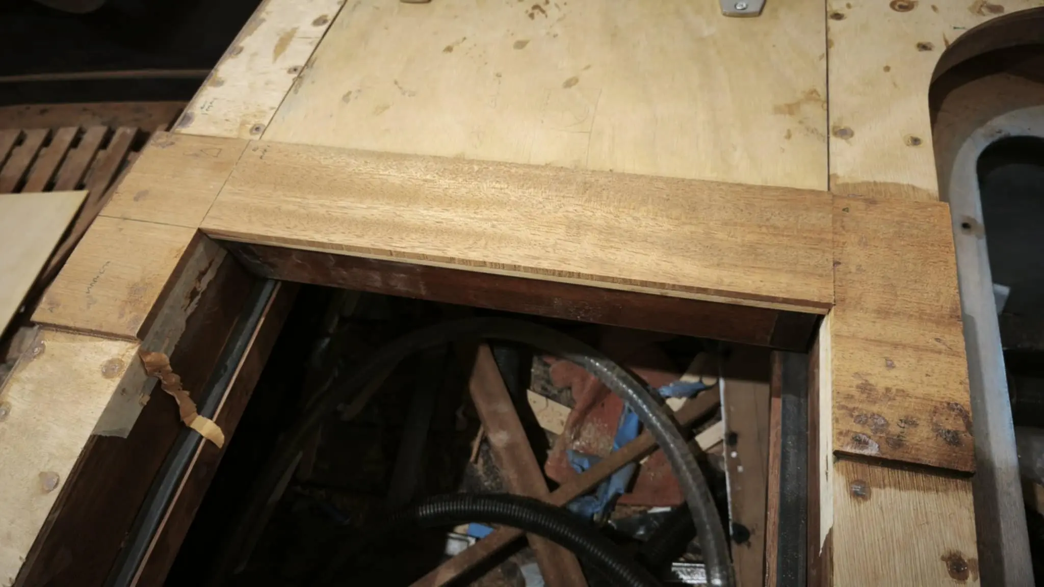
The uprights were glued in too, so we now have the rectangle the locker lid will sit in.

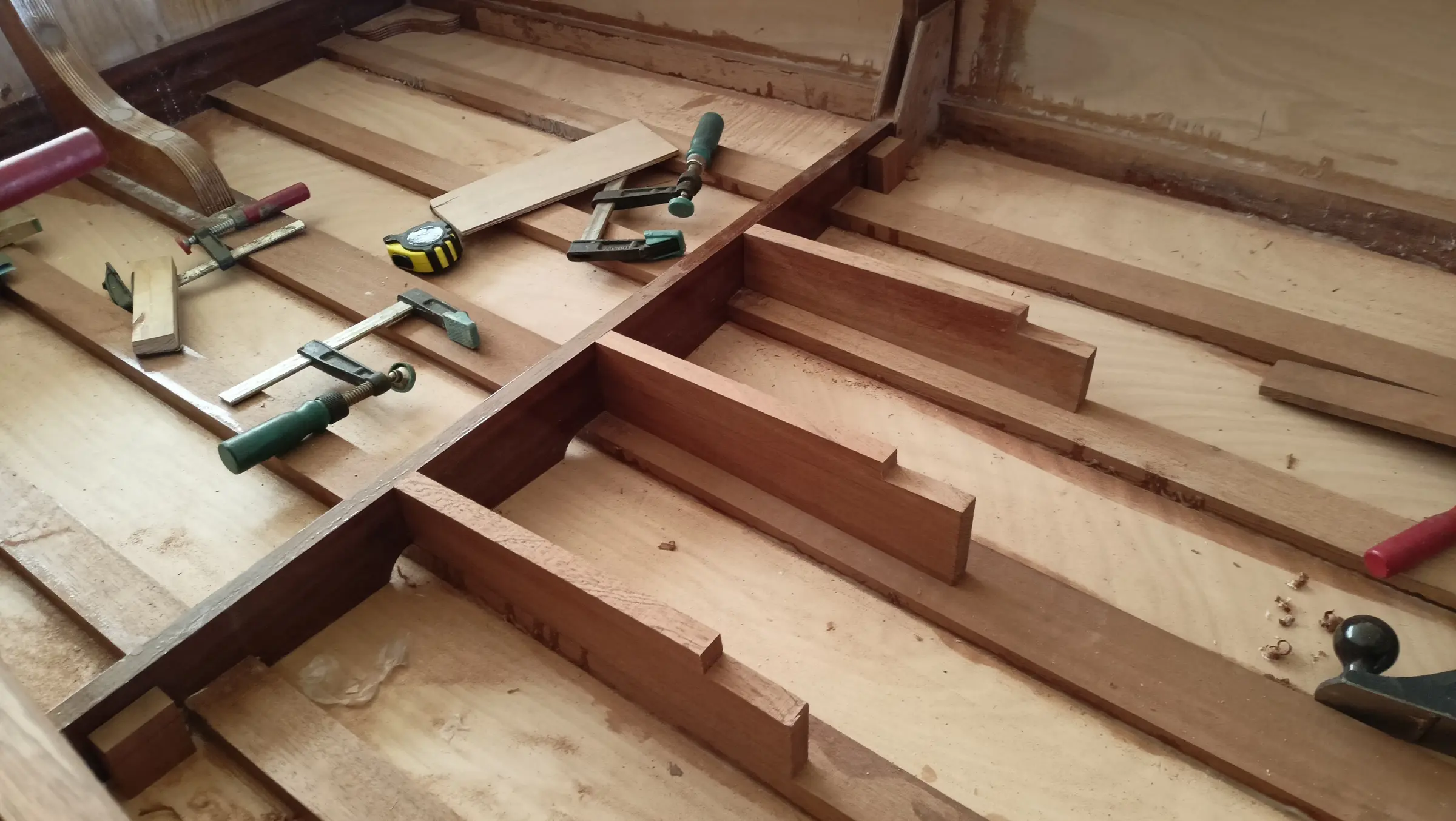
The four pieces that make up the rectangle have a peculiarity. While all four are square to the floor, the two athwartships pieces (forward and aft) are not at the same height. So the two fore-and-aft pieces were not cut square at their ends. That creates the problem that for the lid to fit the opening perfectly it will have to be made to match.

The pieces were cut at the right angle (about 85 degrees) after endless trial fitting.

As can be seen in the photographs, I have left a gap all the way round. It is about 4.5 millimetres. I do need to check the lid will open though. So I drew a little sketch in AutoCAD simulating the lid. I can see that the diameter of the circle centred on the hinge, with the bottom of the lid as its radius, is 1.36 millimetres more than the gap I have left. A very small problem, I will take a little off the bottom of the lid and it will open. I do not want to leave a bigger gap because it would look bad. See the photograph below and the video at the link, which explains how I check whether the lid will open or not.

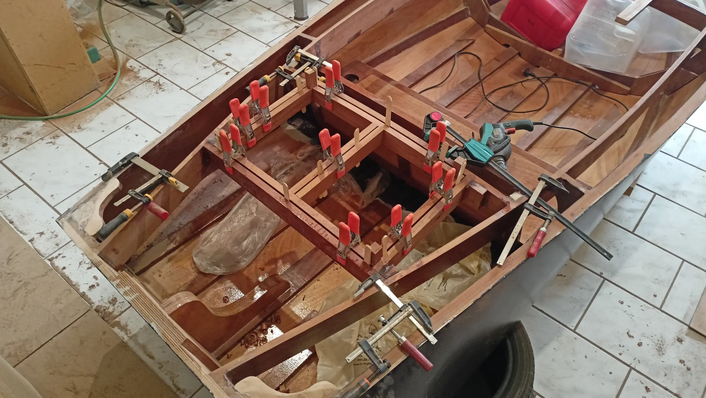
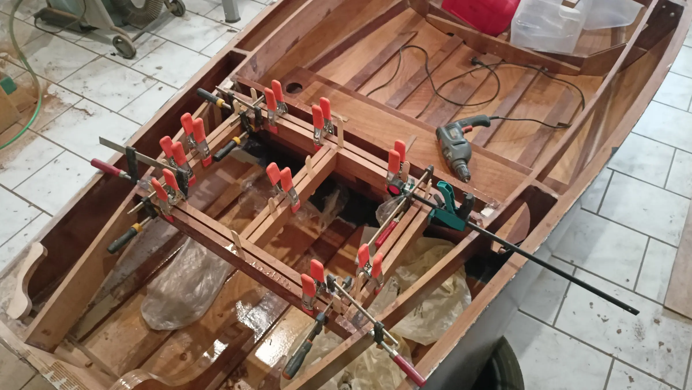
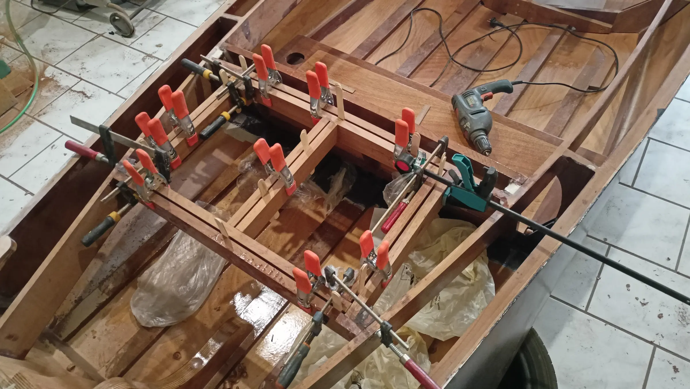
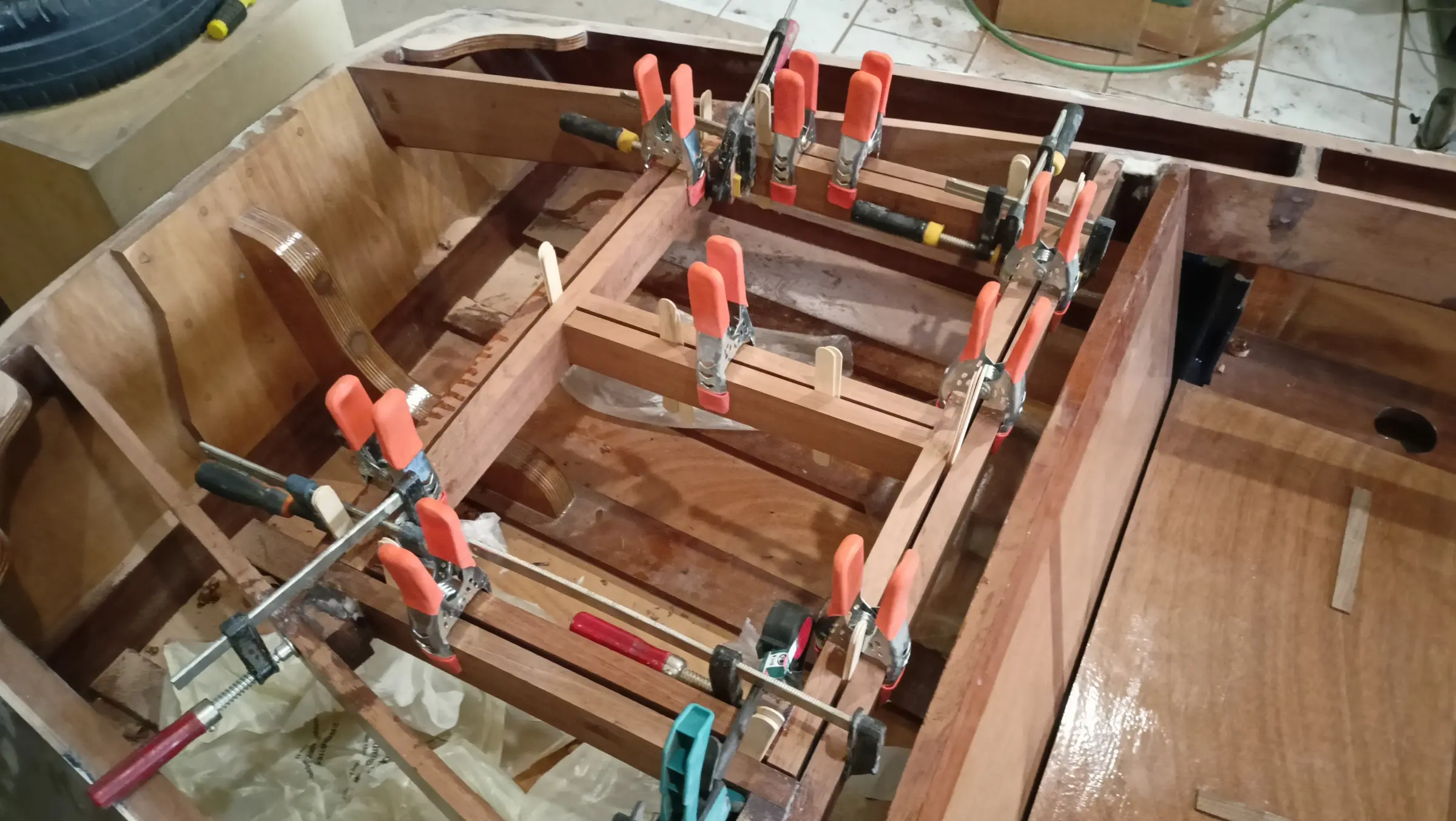
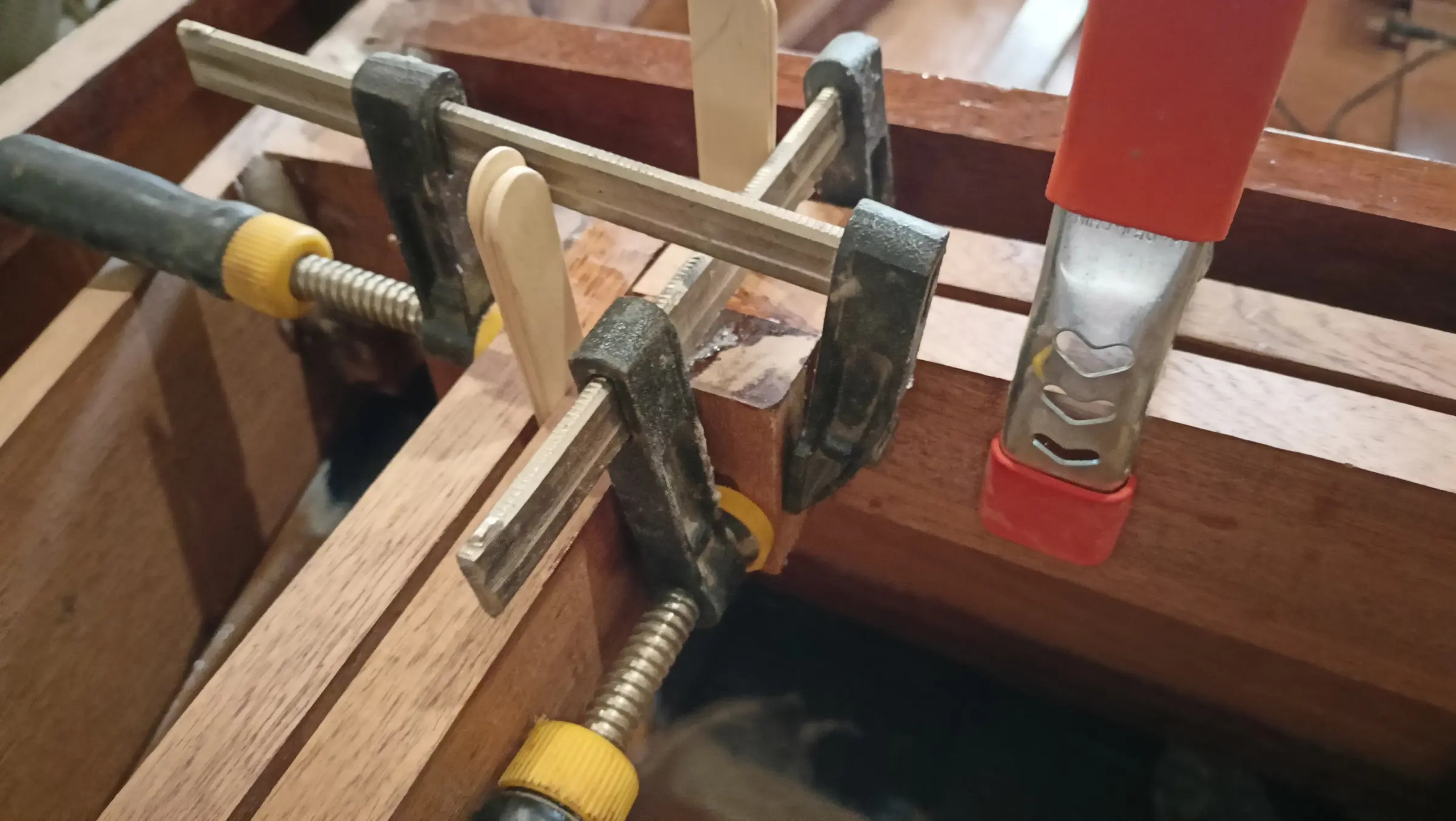
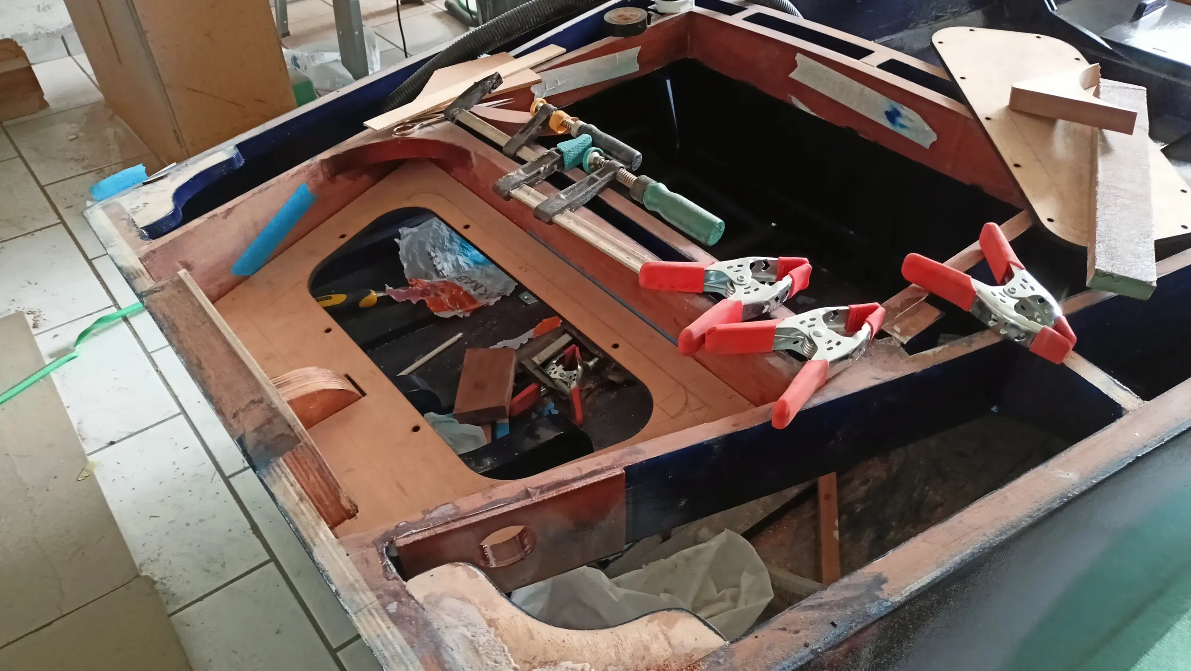
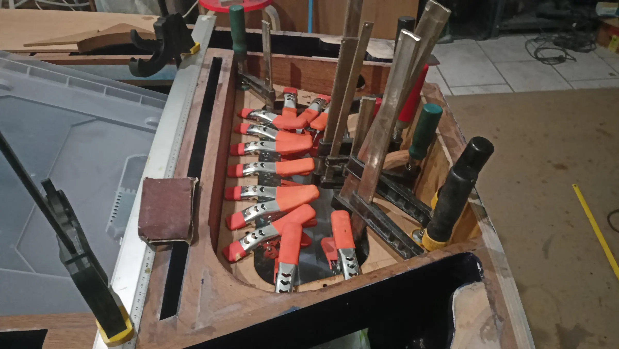
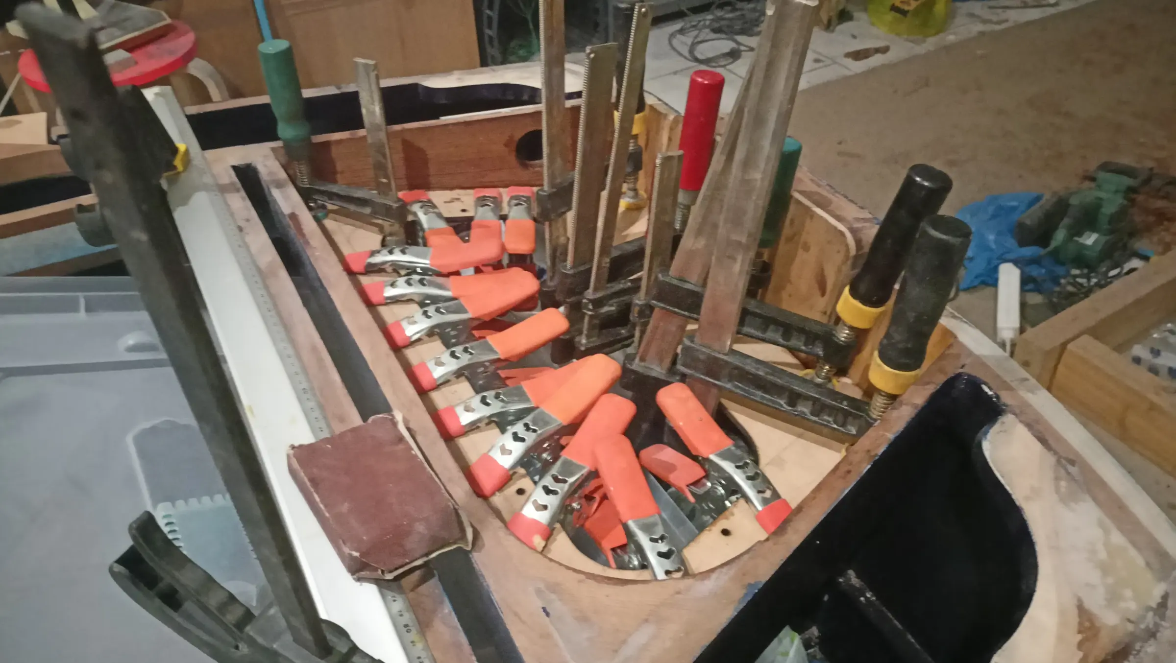
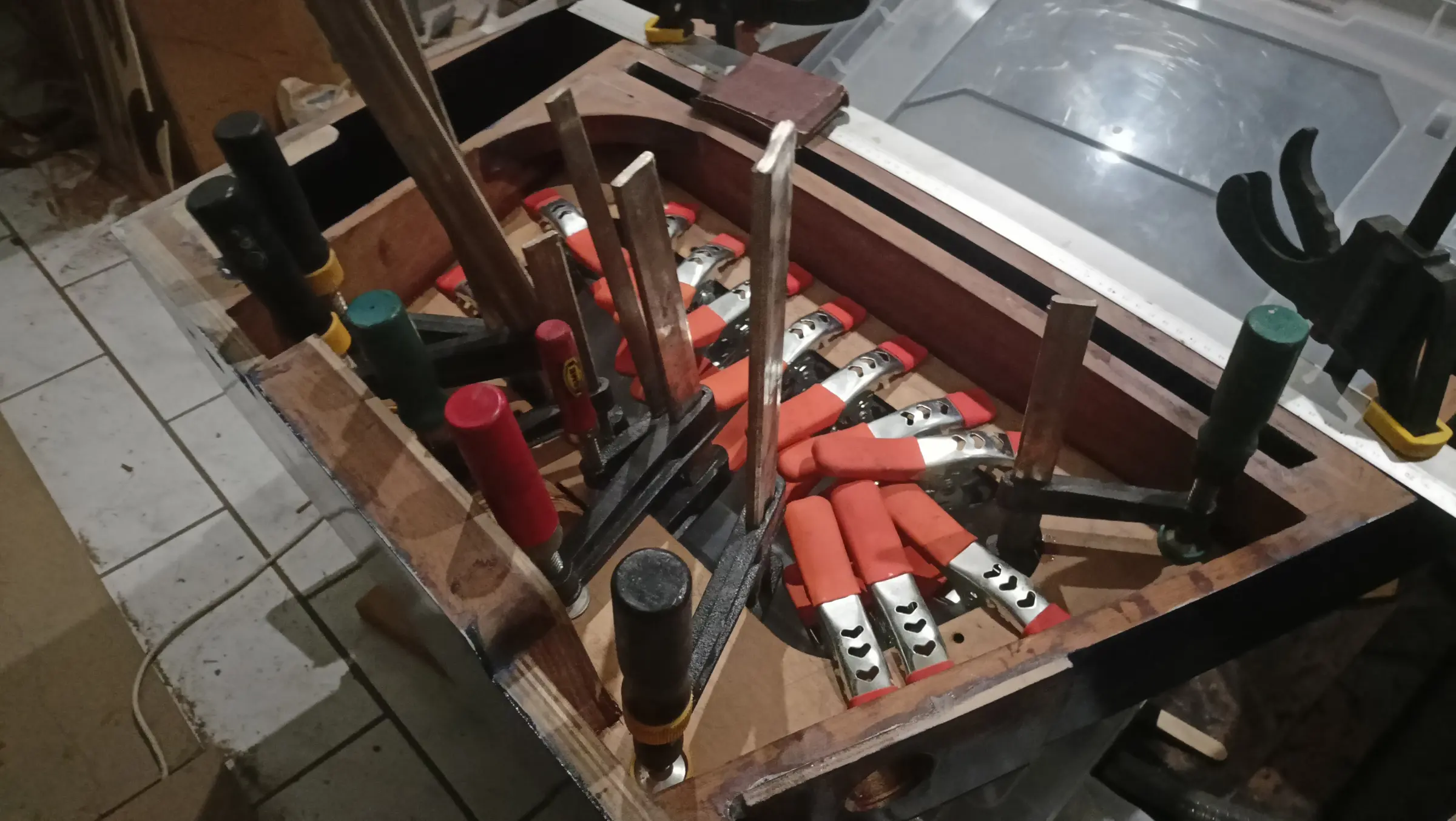
The lid has to match the forward and aft pieces perfectly in height, as they have been cut to the same curve (the aft piece has not been glued yet). That is because the plywood will then be glued over the top and it has to bed down perfectly everywhere. For that reason I decided to clamp the lid up with absolute accuracy, exactly as it is at the moment, unglued, and glue blocks into the corners. That way no piece can move at all and I keep its geometry correct. Having tested that I could get clamps on it, I went ahead and glued the four outer blocks.

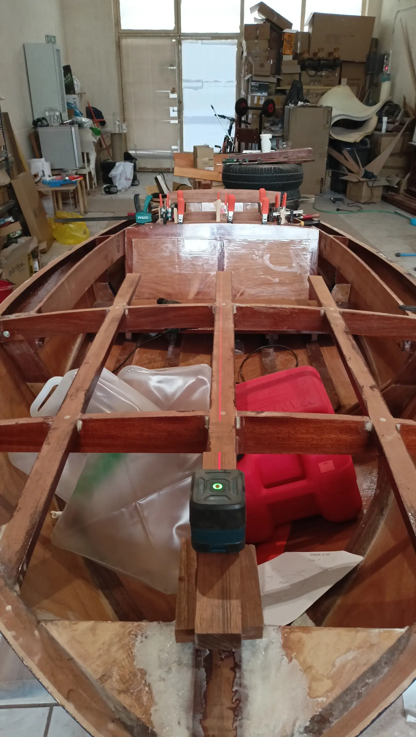
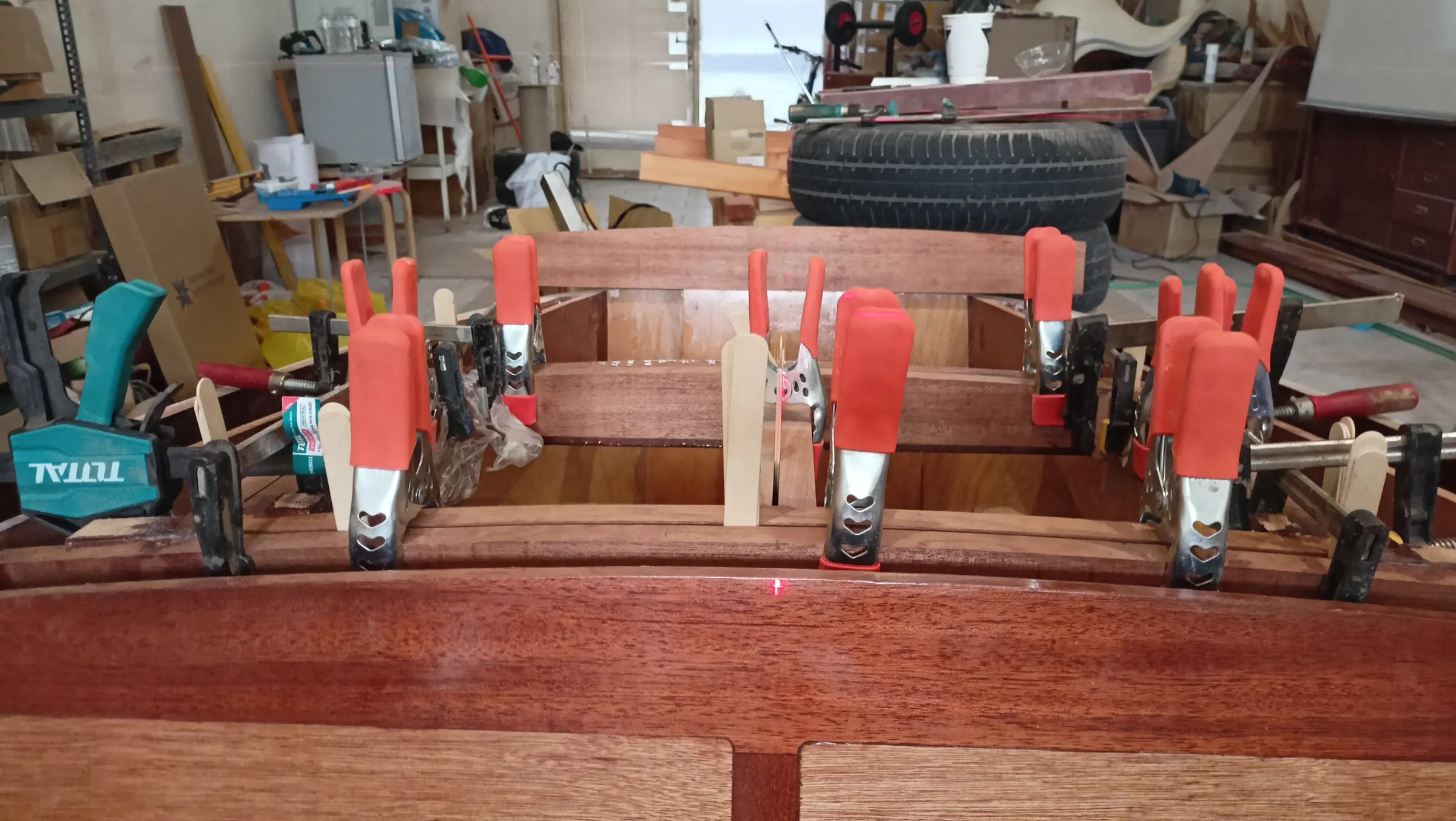
To glue the two inner pieces I need to find the boat's centreline. It was found with a tape measure, and confirmed with the laser.

However, I decided I should not glue the two inner pieces because how the locker opens matters. Depending on how it opens it will have a different hinge and therefore a different arrangement of the pieces it bears on. So those will be glued later. The last piece aft of the locker will also be glued later, because I am thinking all the cables running to the engine will probably come out there. So I want to test how much of a gap is needed between the two pieces, so they can turn and fit between them. (The locker work continues in Interior work No. 4.)

Video: https://www.youtube-nocookie.com/embed/Q9-z8-xdYMY


Buying the outboard

Choosing the outboard was a very nerve-racking process, with an awful lot of hours of reading. On one hand the company that designed the boat in 1956 recommends an outboard of up to 9.9 hp, on the other a lot of people who have built it have fitted considerably more. Most have gone for 20 or 25 hp, two-strokes, to keep the weight on the transom down.

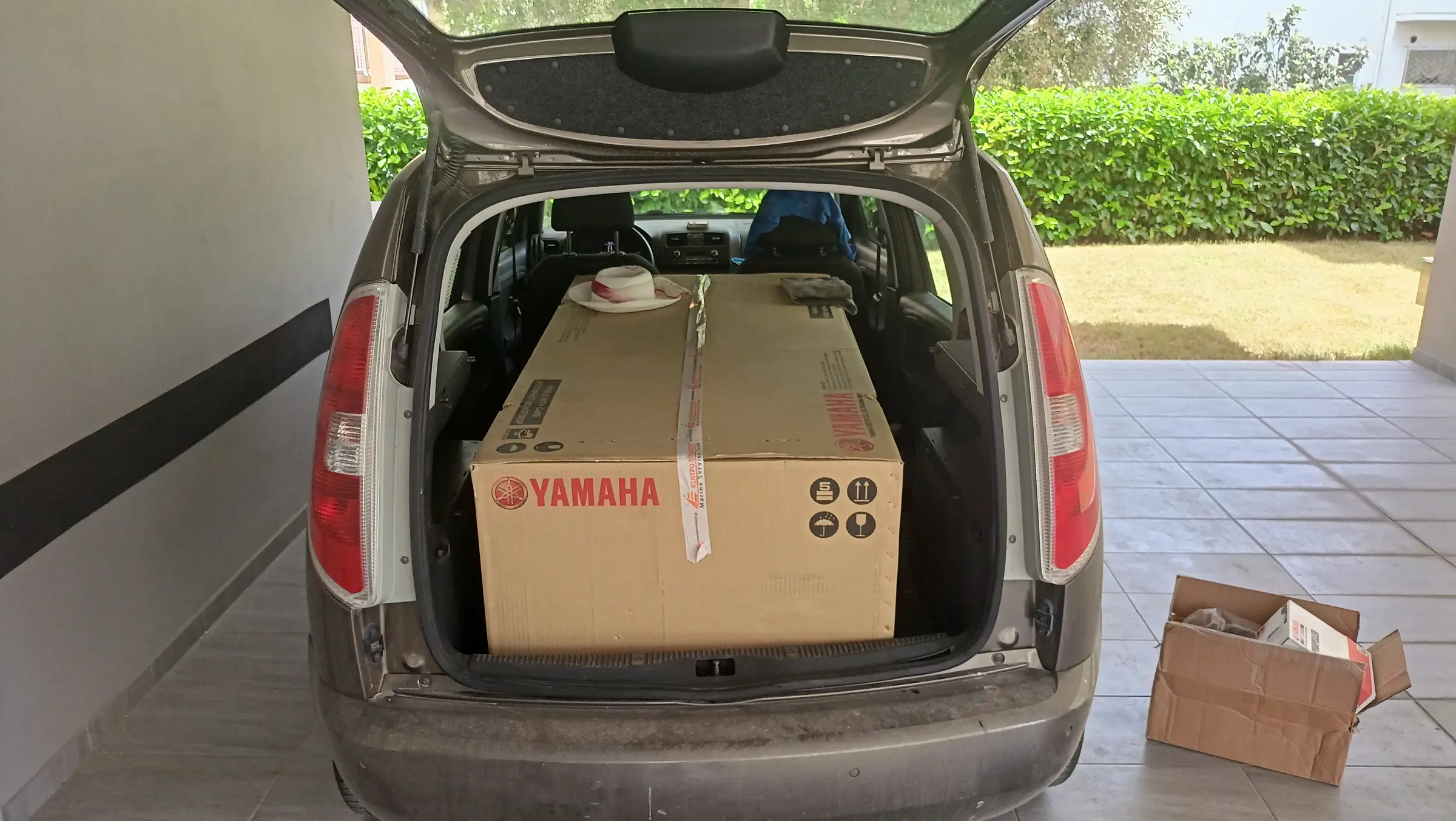
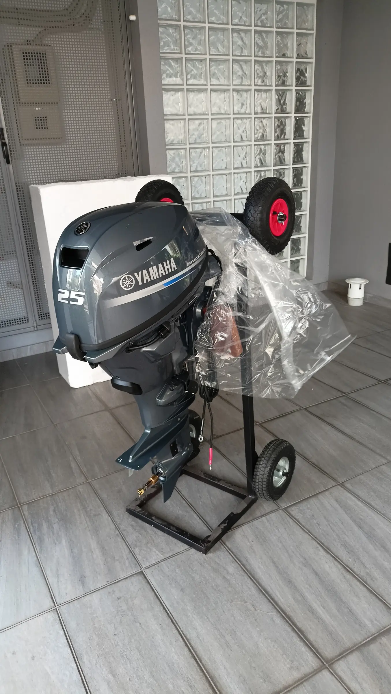
After looking hard for a used two-stroke without success, I decided to buy new. To my great surprise I found that the new Suzuki, Mercury and Tohatsu engines are now very light. The 15 and 20 hp are essentially the same engine and their weight was around 48 kg without power tilt and 53 kg with it. I had almost settled on the Tohatsu with power tilt when my eye fell on the Yamaha 25 hp, which I had not looked at until then because the smaller Yamahas weighed a lot more than the equivalents from the other makers. As it turns out, in 2017 Yamaha replaced the previous model with a new one (the 25G), which is now a twin cylinder, dropping its weight by about 15 kg. So the short shaft with remote control and without power tilt weighs 56 kg. The weight is marginal for the size of the boat and I did not know what to do.

So I started looking for other people who had fitted outboards of a similar weight to this boat. I found two cases, one who had fitted a 20 hp Yamaha weighing 57 kg and a second who had fitted exactly the same model. So I made the decision to buy the 25 hp Yamaha.

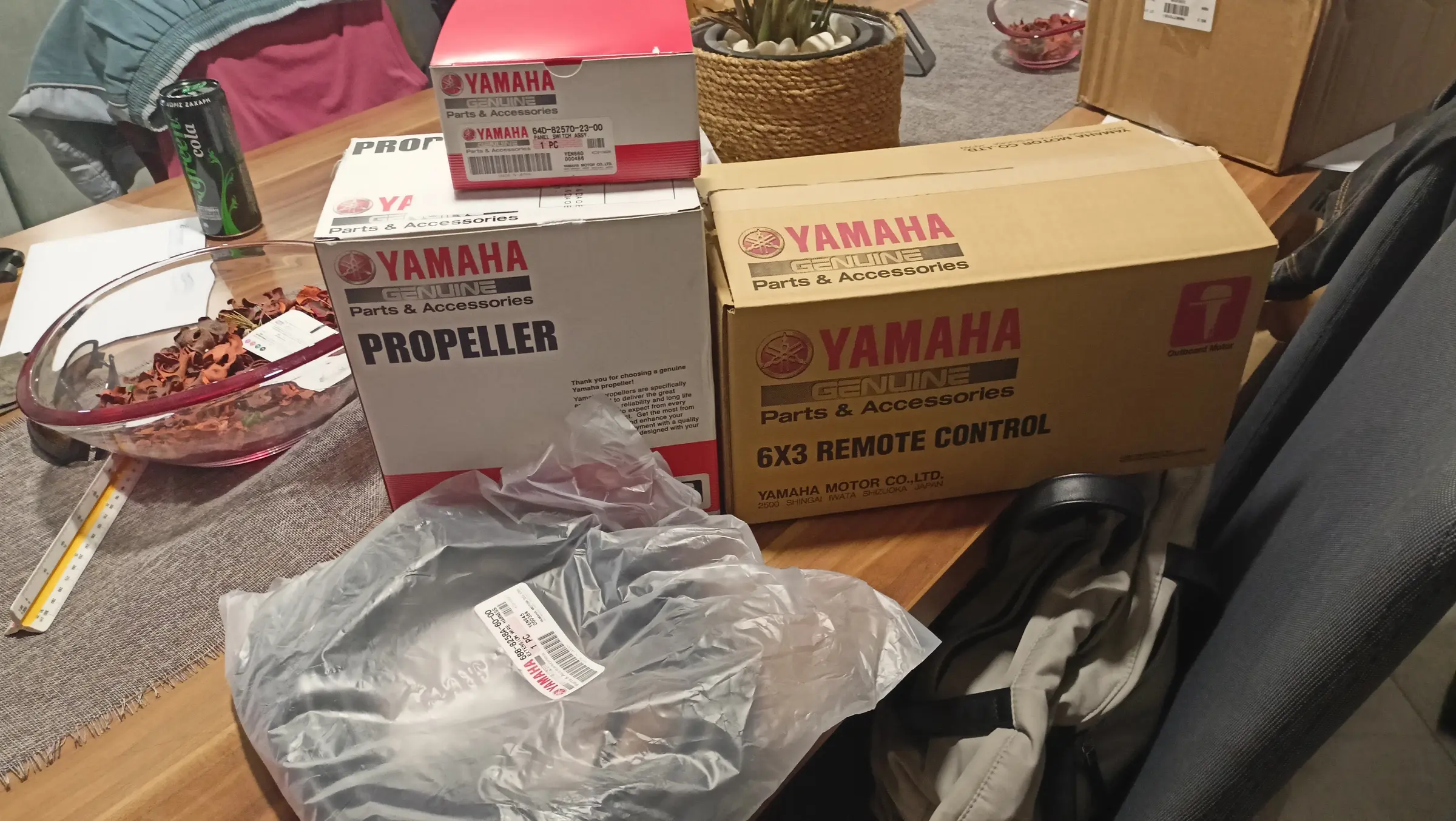
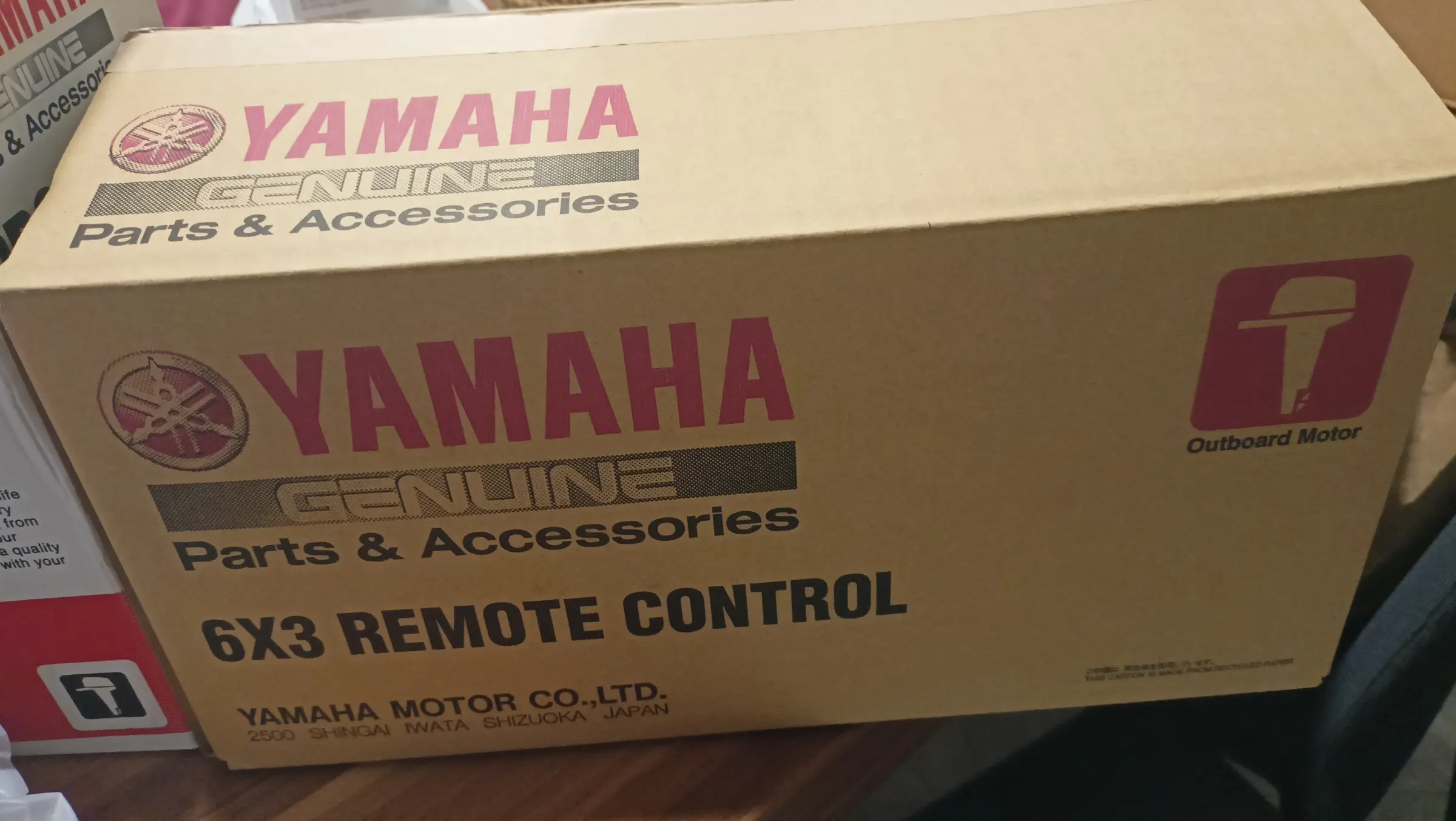
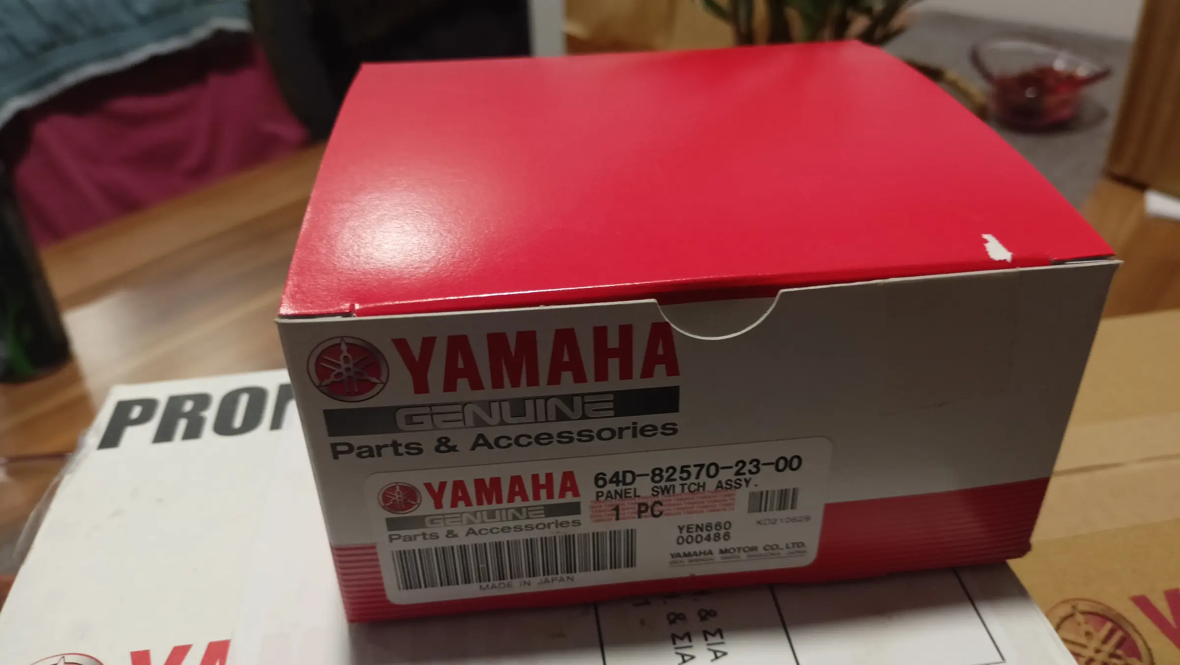
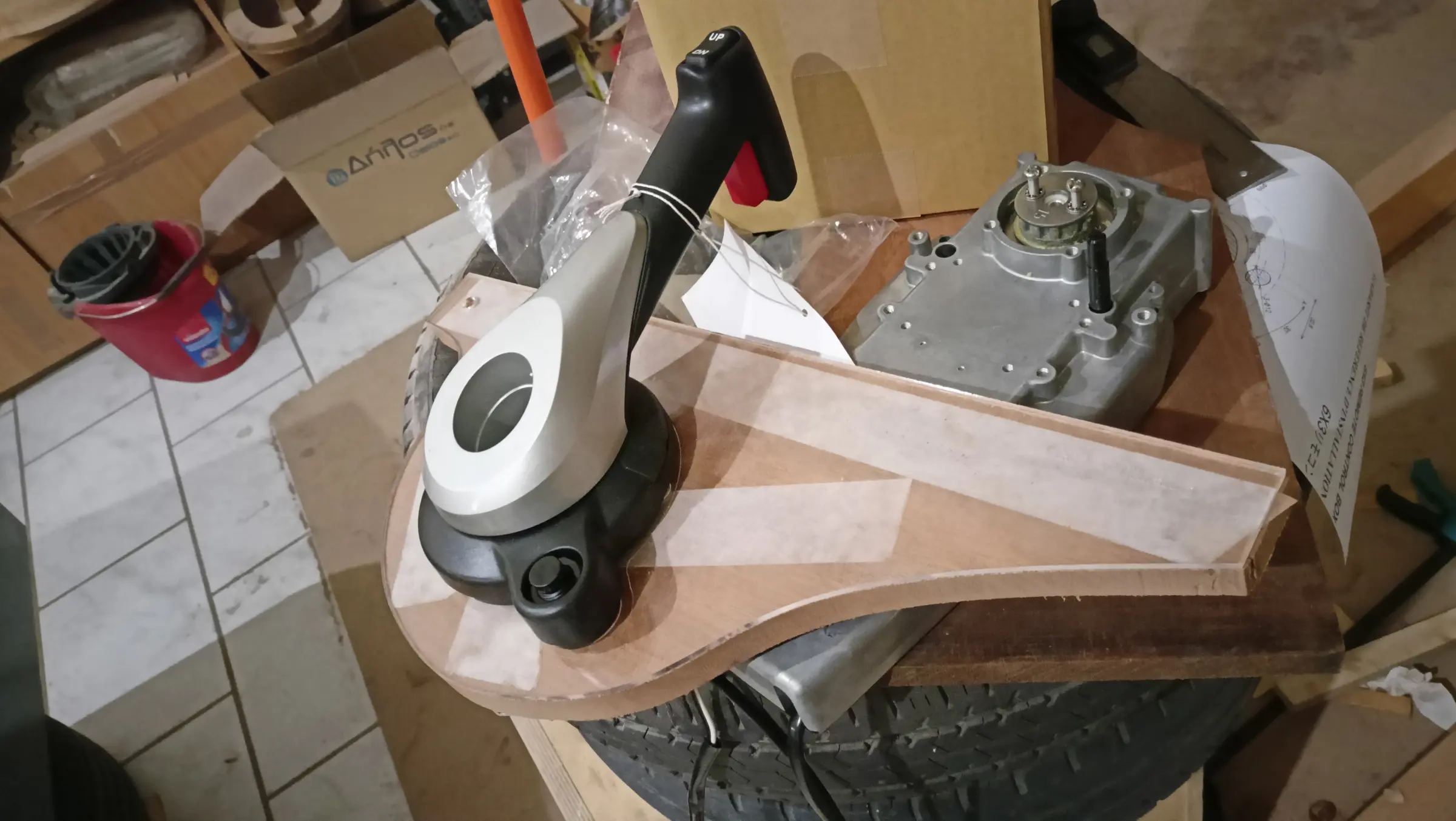
The next search was about replacing the control box with a flush-mounted one that looks better. I found that Yamaha have one that suits me, the 6X3. In fact they agreed to swap the standard control box for the flush-mount one, which of the other brands only Mercury had agreed to, on payment of the difference. Fitting this control box makes things slightly more involved, because I will have to fit the key separately. On the standard control box the key was on the box itself.

A nice surprise from Yamaha was that they include a multifunction gauge with the outboard. The gauge was not in stock, so I took delivery of everything else.

I bought it very early because I need to start thinking about installing the steering system, the dashboard with the gauge, and the size of the cutout in the aft end of the boat so the outboard can move as it should with the cables, and can tilt up without fouling the woodwork. One problem I will have to solve is how I get to the back of the boat to tilt it up. I am thinking the locker should not open backwards but to the side, so it does not get in the way.

Some photographs of the outboard on the day I bought it.

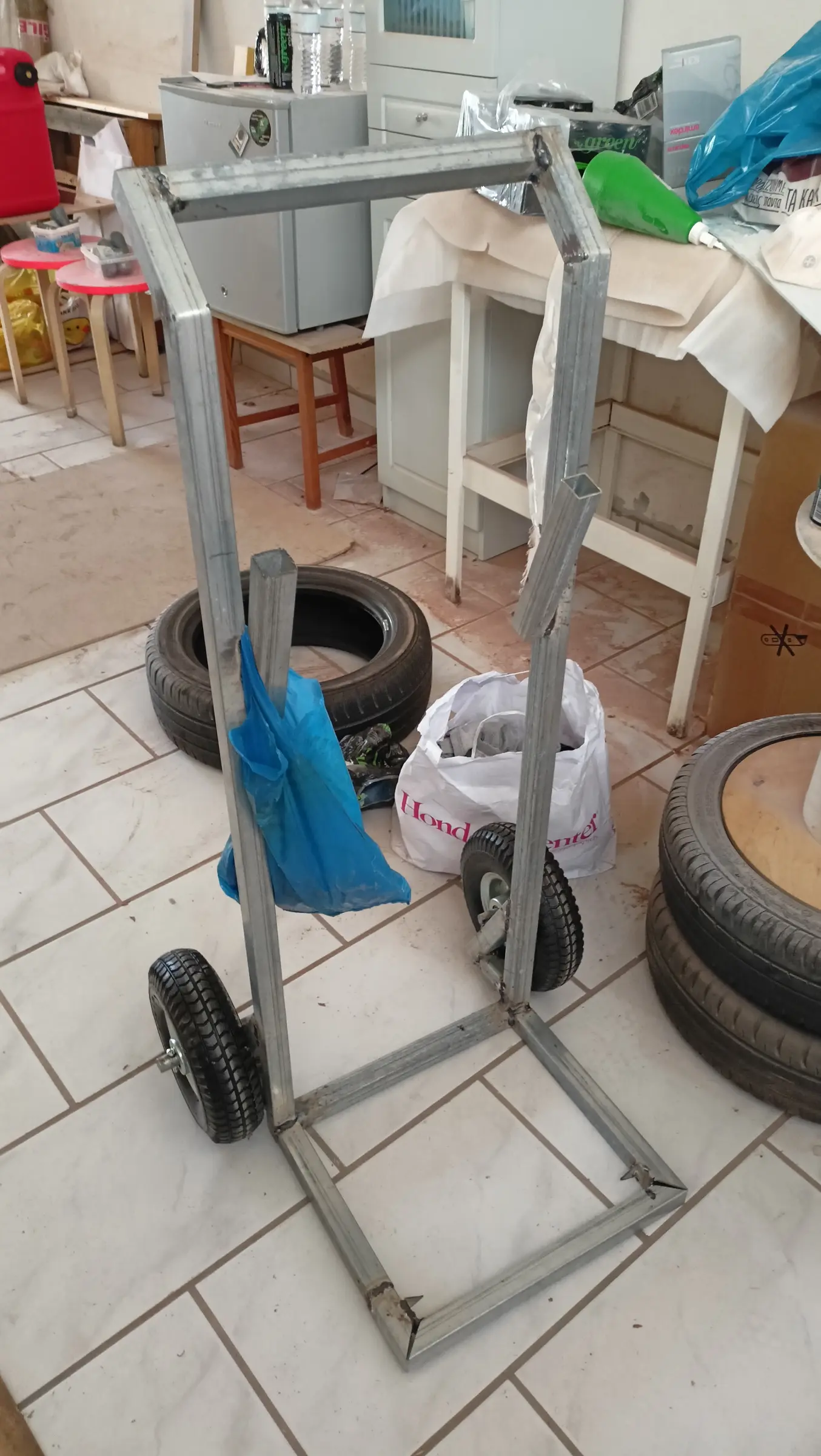
The boat has been turned over again so I can carry on with the work inside. Alongside that work I will build a base for moving the outboard around easily, both with the car and inside the workshop. Something like the one below.

Video: https://www.youtube-nocookie.com/embed/2TbshyXtTpI


12.5 h

Building a dolly for the outboard

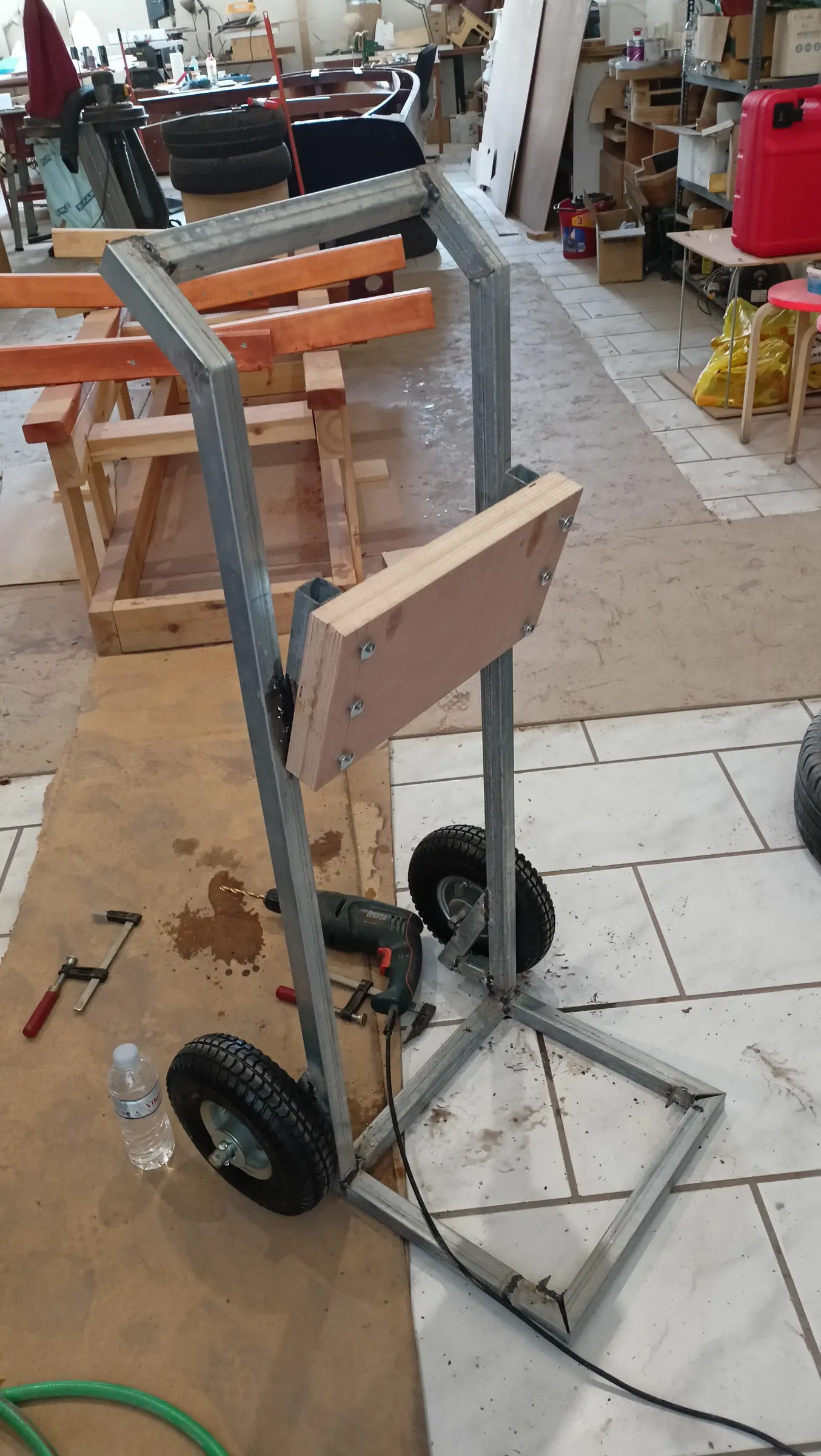
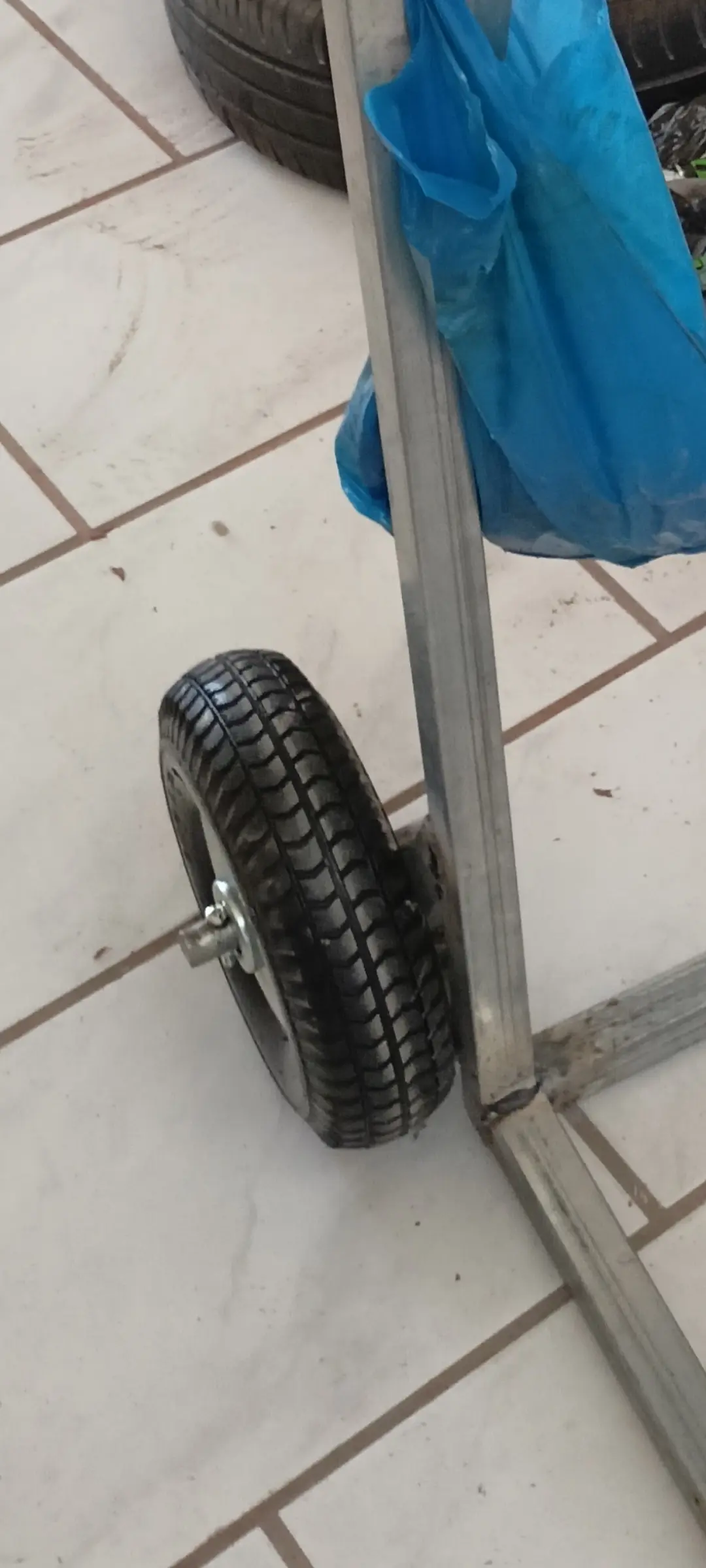
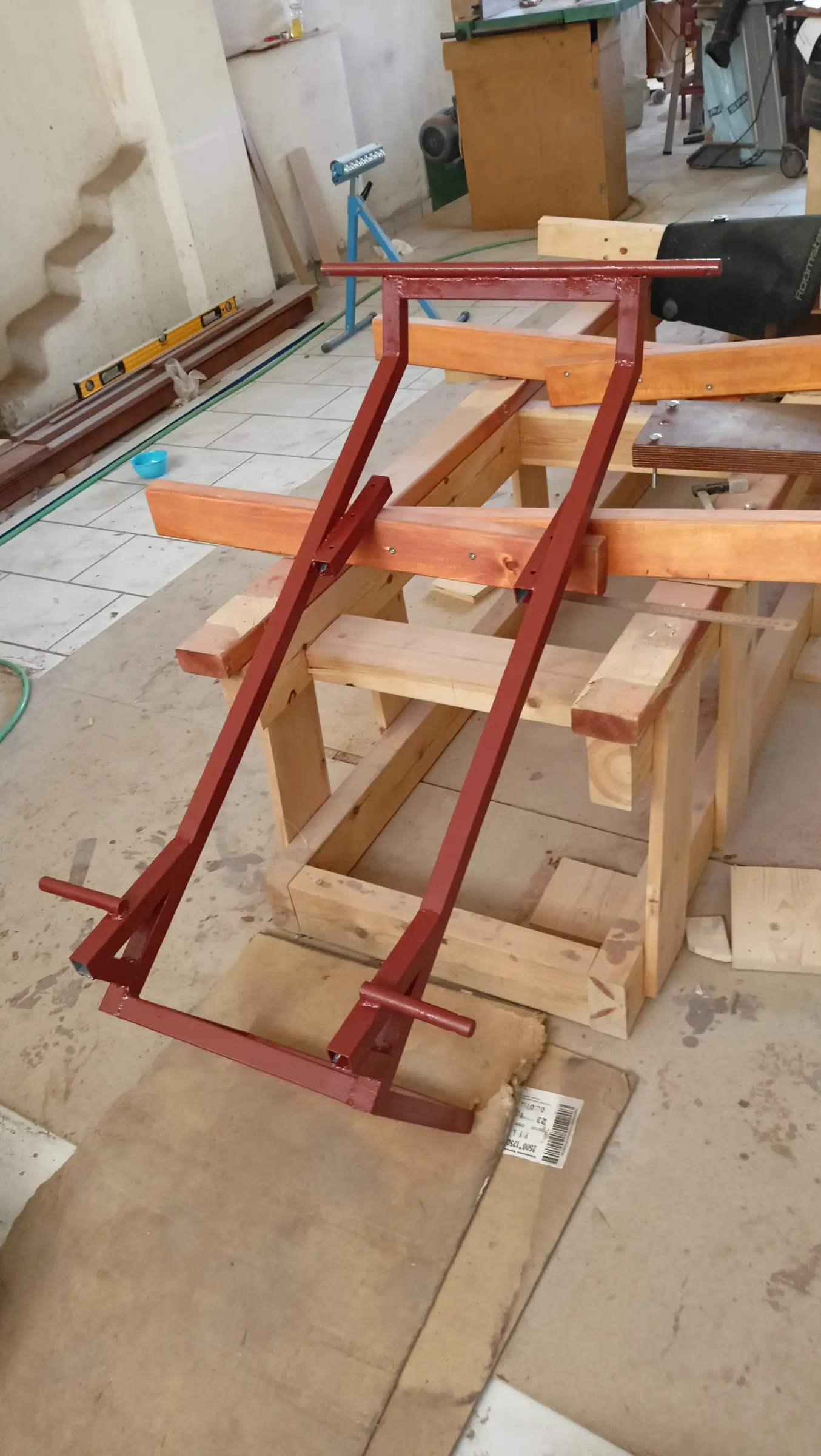
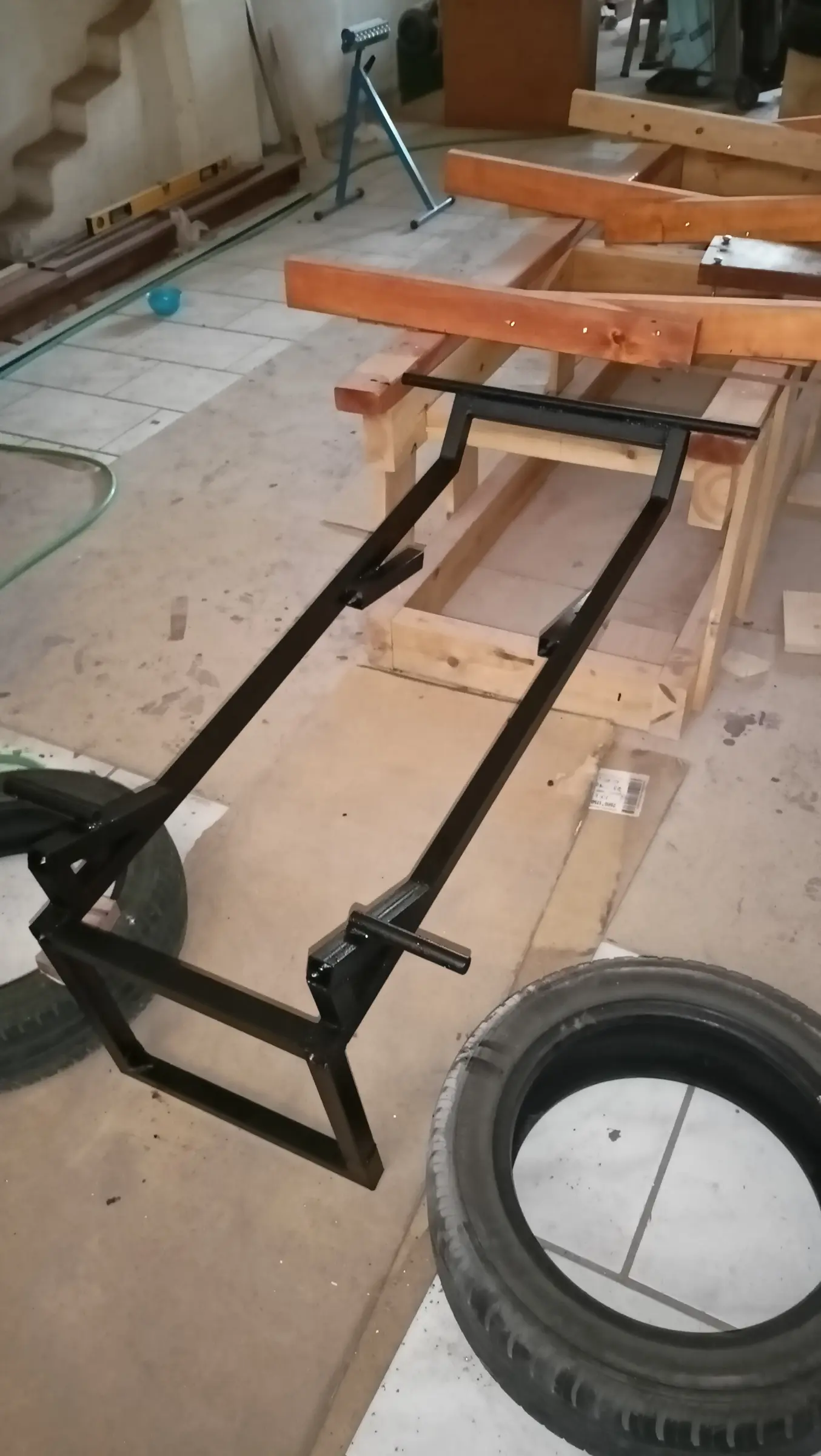
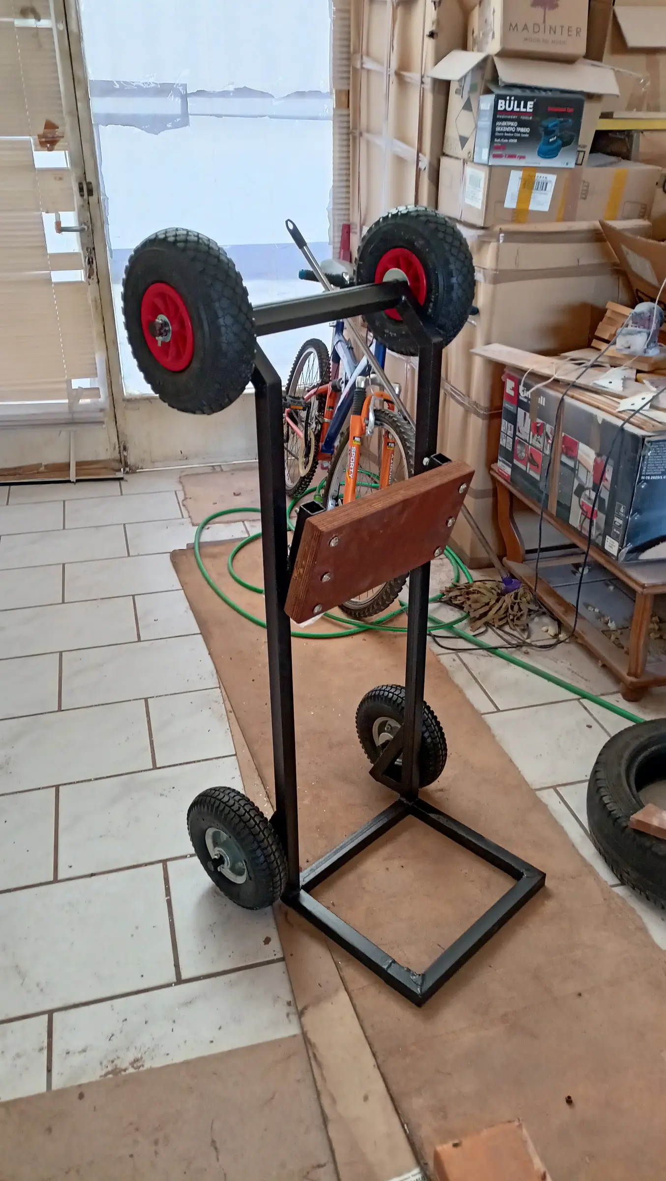
The outboard I bought (Yamaha 25 hp) is by a wide margin the lightest 25 on the market, being a twin cylinder (56 kg), but there is certainly no way a "middle-aged" man with a bad back is going to carry it about. So I decided to make a base that can go into the car very easily. The idea is to have wheels on the bottom so it can be wheeled around, and on the top so it can slide when it is laid over in the car. The base is shown in the photographs below. The wheels on the top have not been added yet, and it has not been sanded or painted.

The top wheels were fitted once the holes were drilled in the axle. It was then given a coat of rust-protective paint and after that the topcoat.

The board the engine sits on is two pieces of 2 cm plywood glued together. Four centimetres thick in total.


38.5 h

Designing and building the dashboard and control box

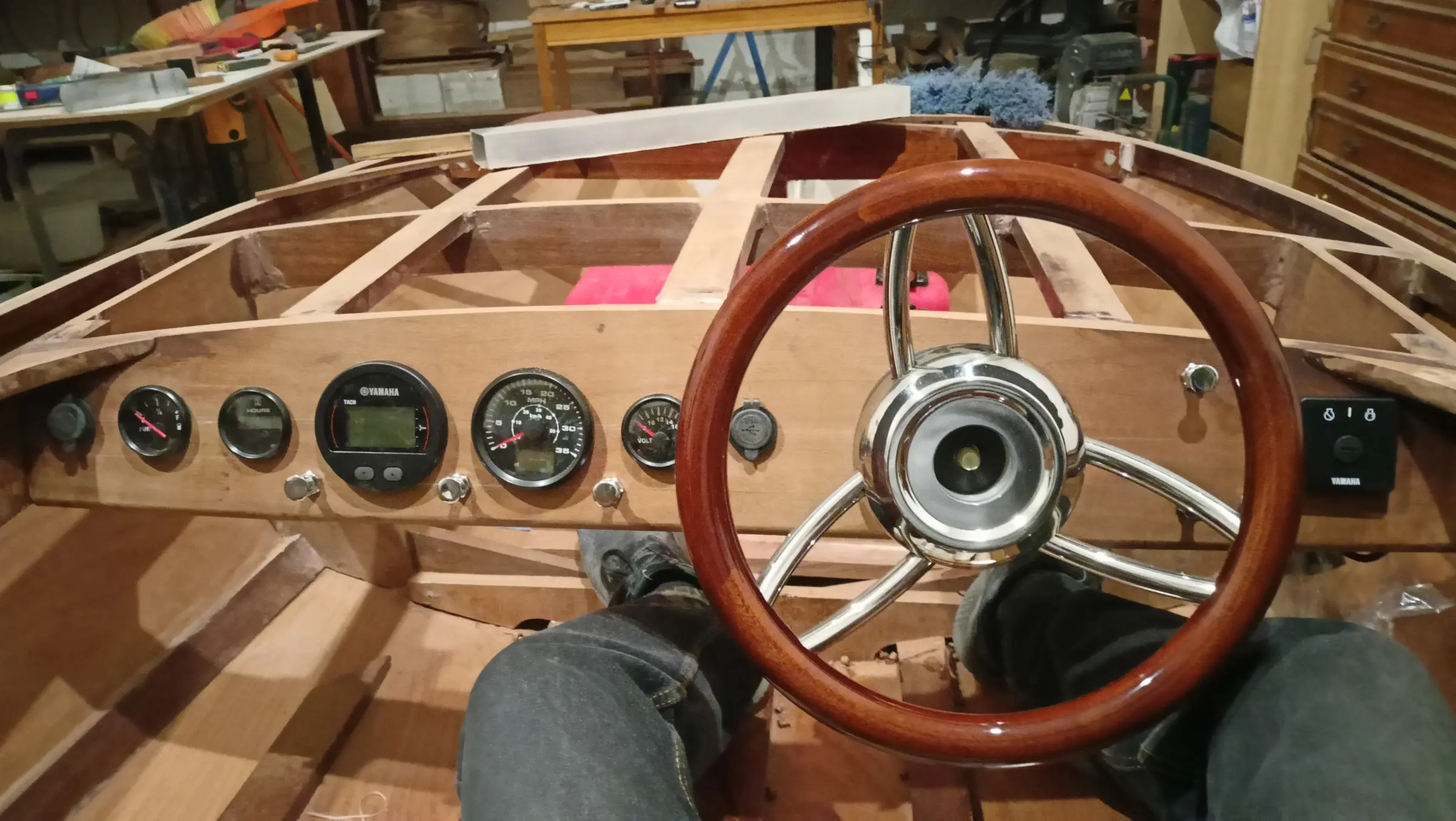
Alongside the work at the aft end of the boat, I started thinking about the shape of the dashboard, and how the instruments would be laid out.

The instruments to be fitted are:

  1. Speedometer

  2. Yamaha multifunction gauge

  3. 12 volt socket

  4. USB port

  5. Battery level

  6. Fuel level

  7. Horn

  8. Hour meter

  9. Switch for the bow lights (red and green)

  10. Switch for the all-round stern light

  11. Switch for lights in the dashboard area

  12. Switches for two pumps

  13. ON-OFF switch

I did a lot of drawings but settled on the last one.

I decided the dashboard would be installed at a 20 degree angle.

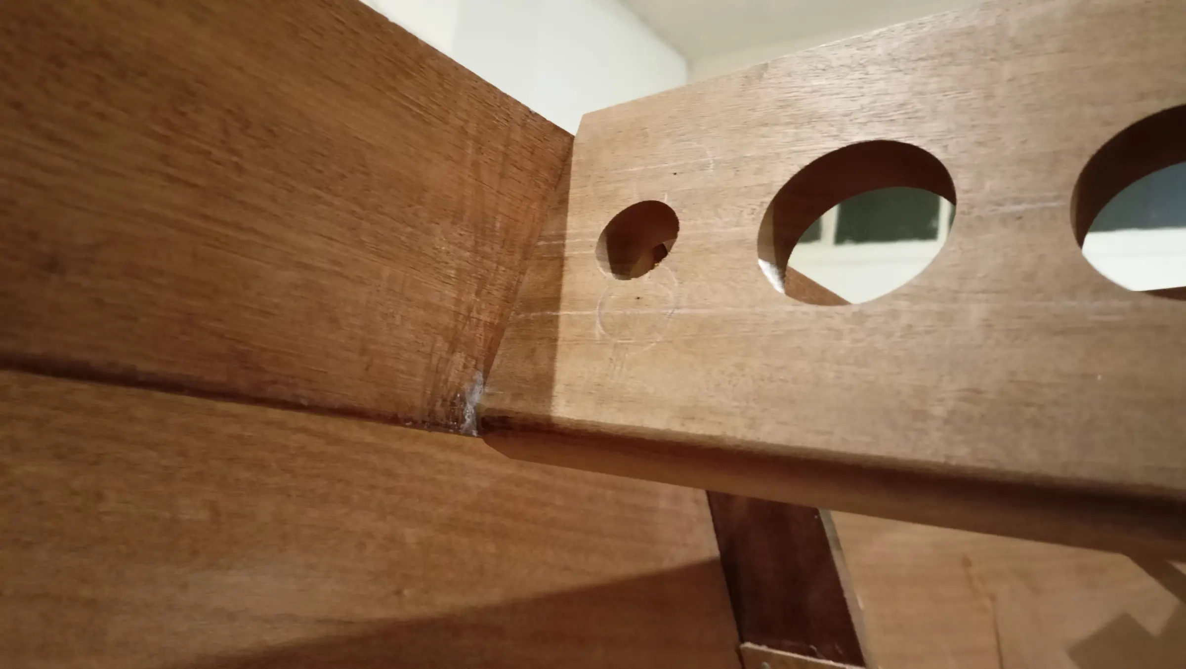
To fit it, I first cut all the fore-and-aft timbers at the forward end that land on the dashboard to the same length. Blocks were glued to the coamings at the right angle, for the ends of the dashboard to be glued to, and the fore-and-aft timbers were cut back so the dashboard would sit on them.

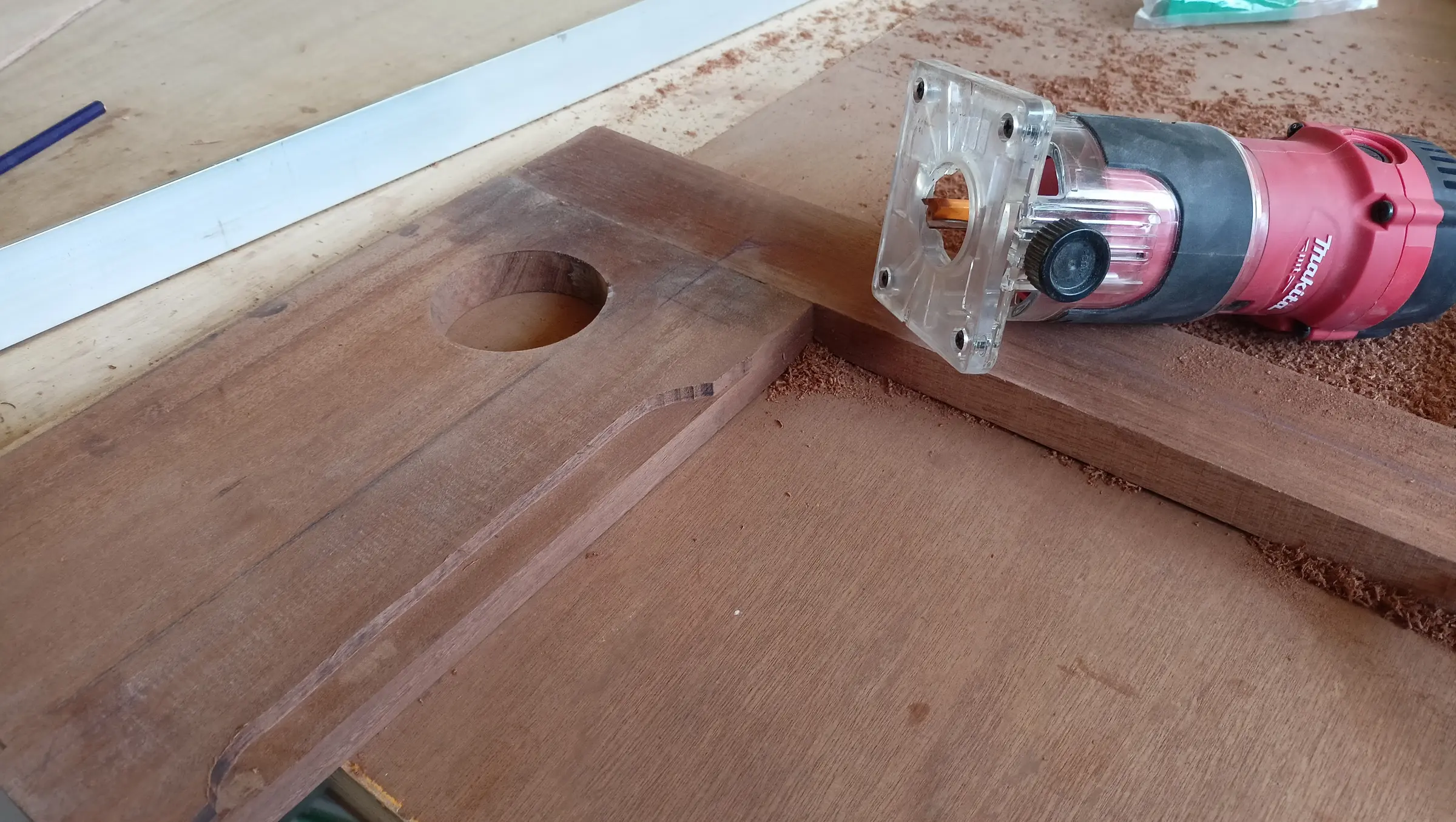
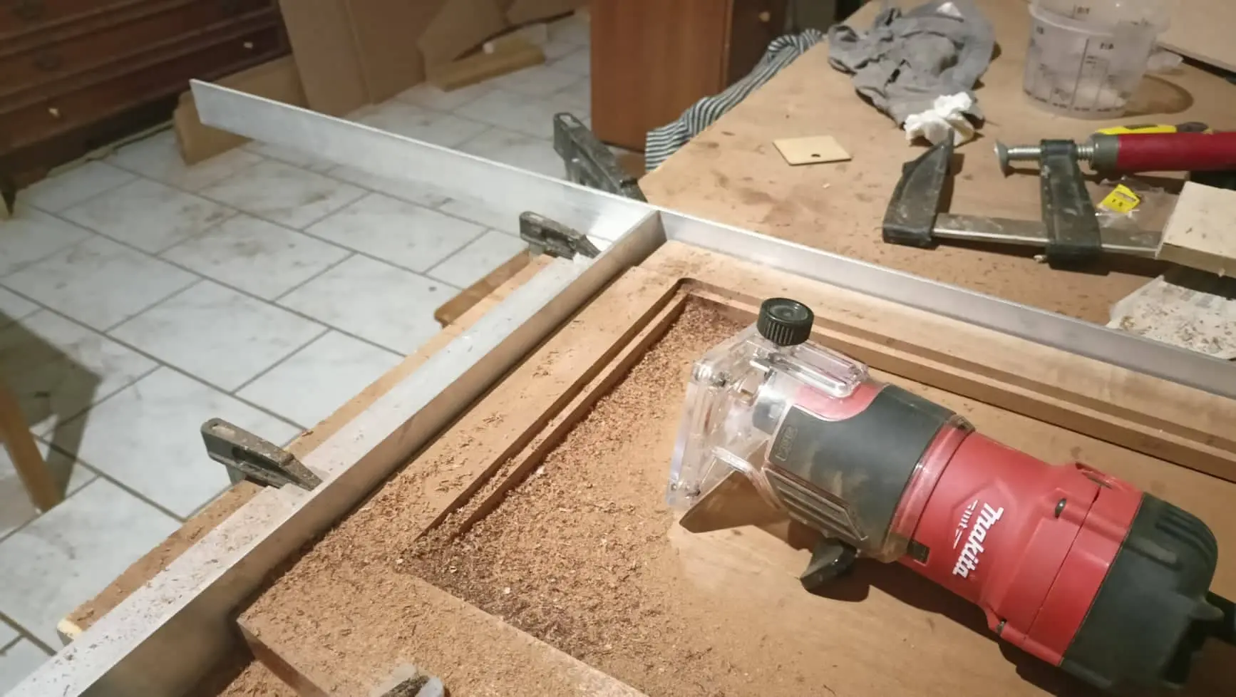
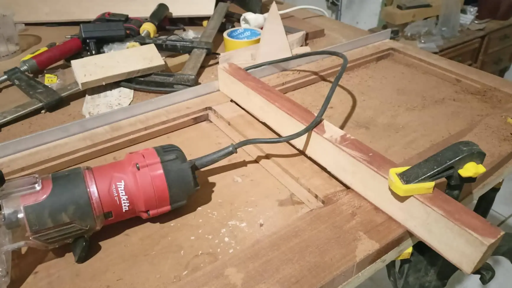
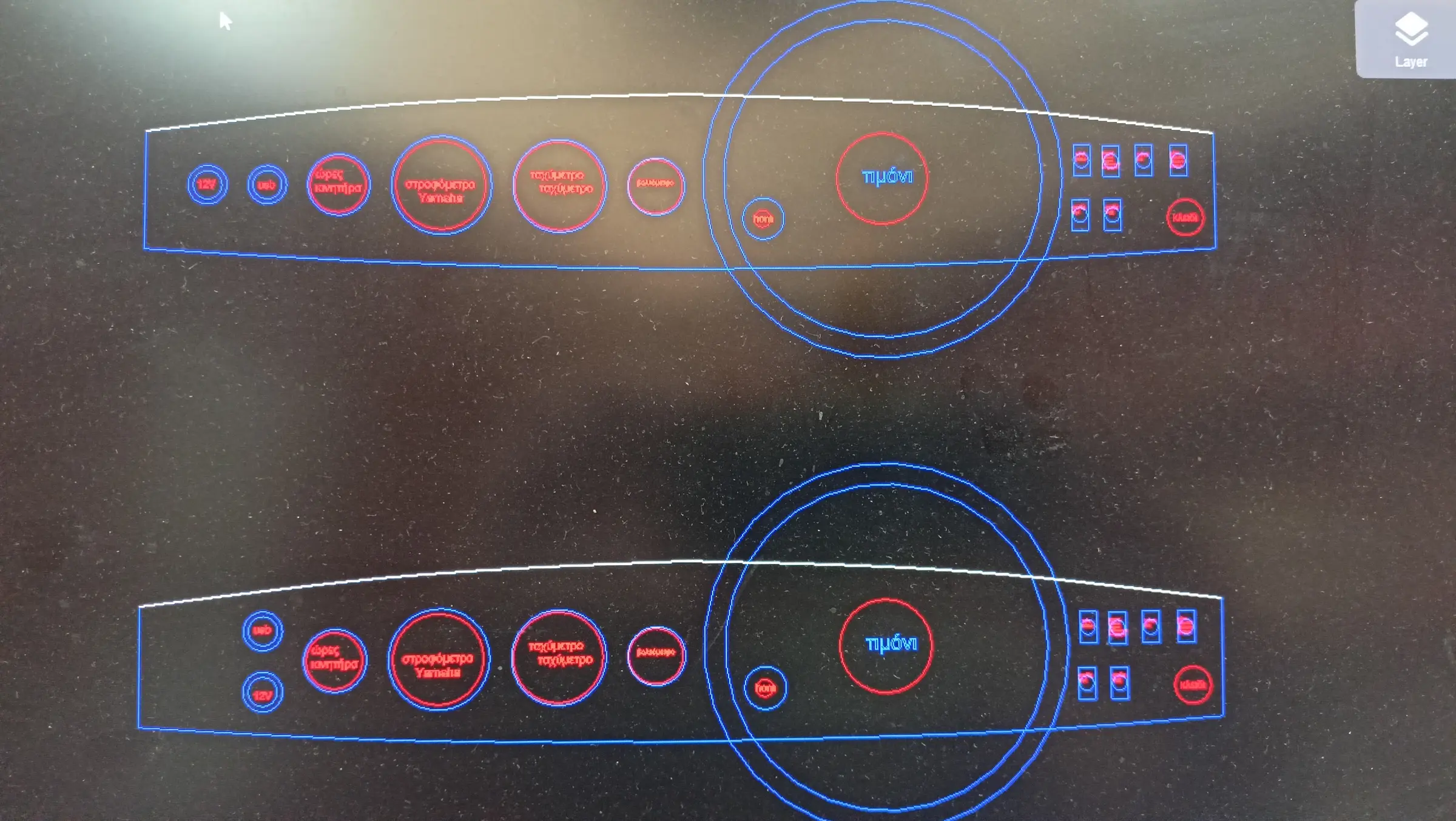
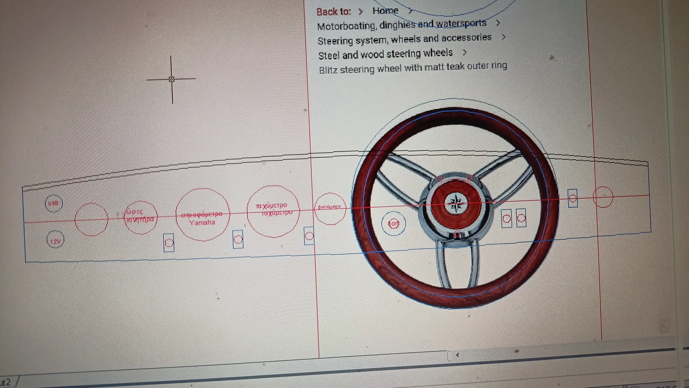
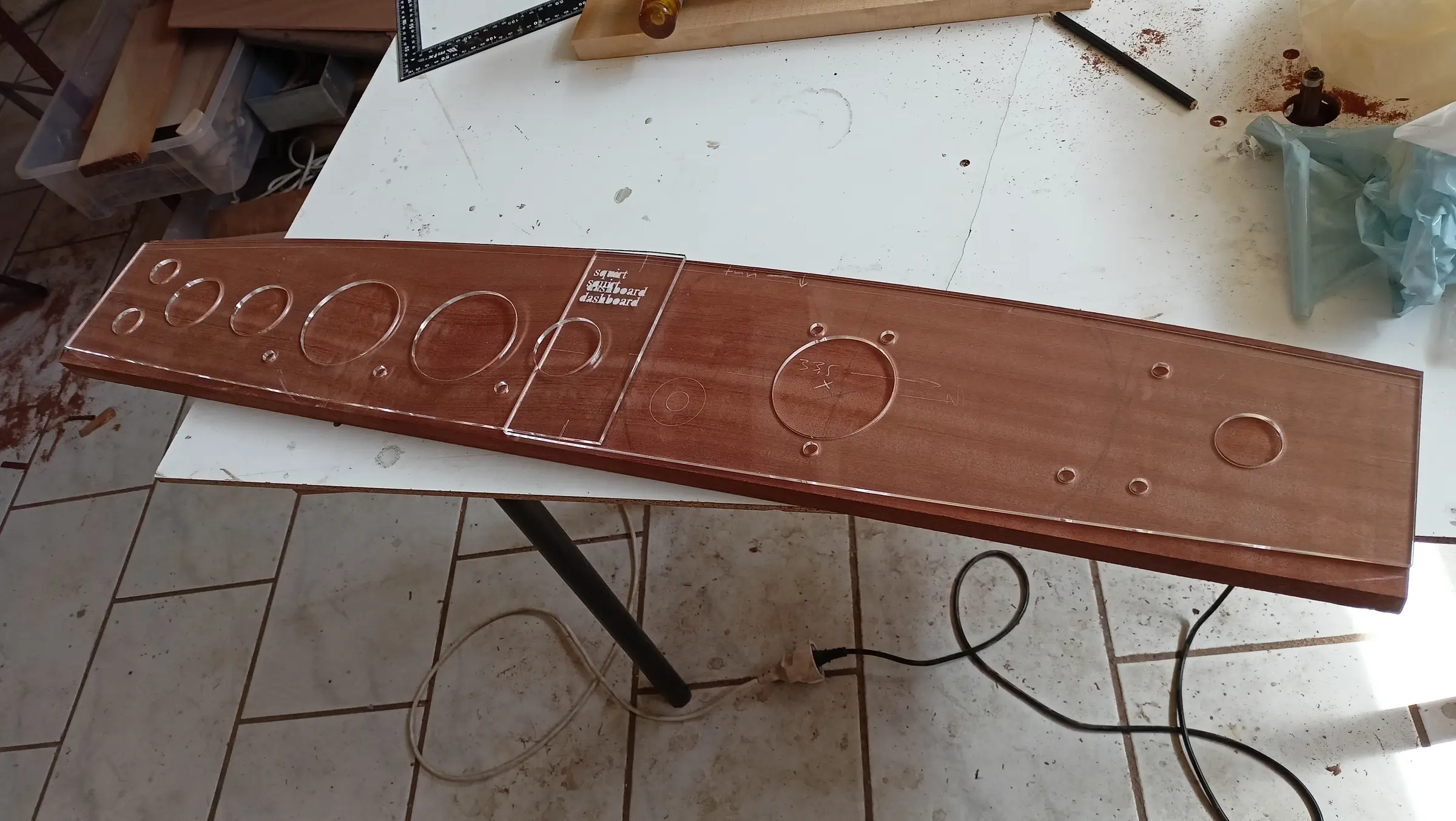
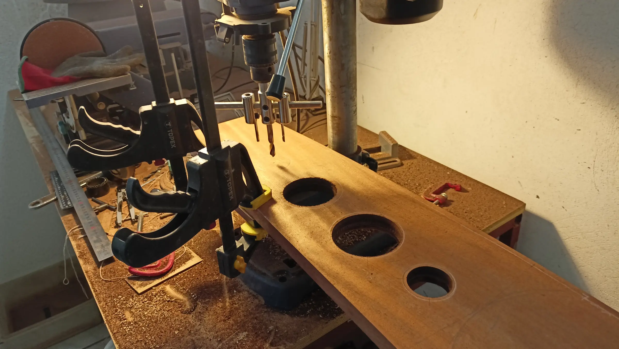
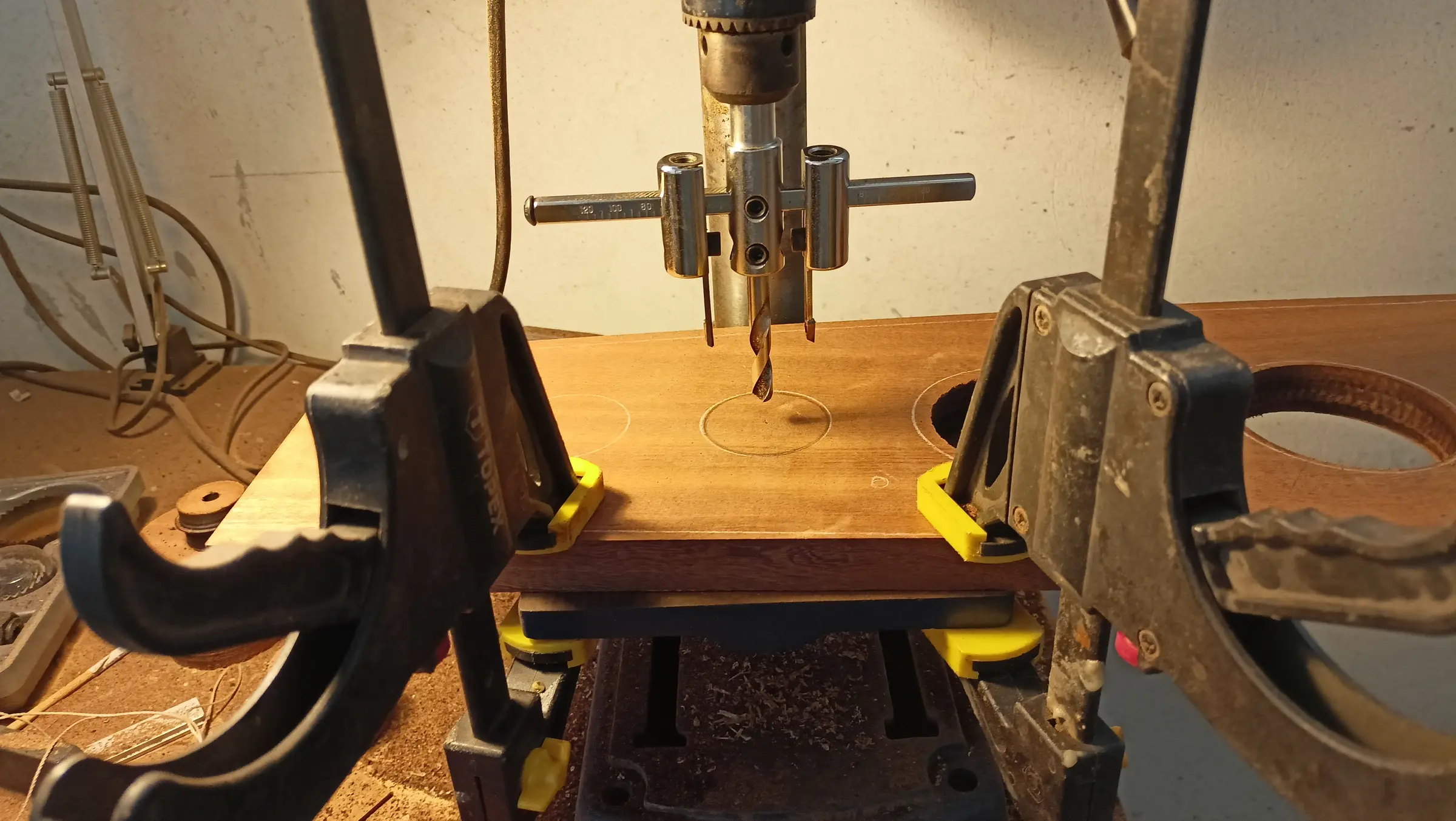
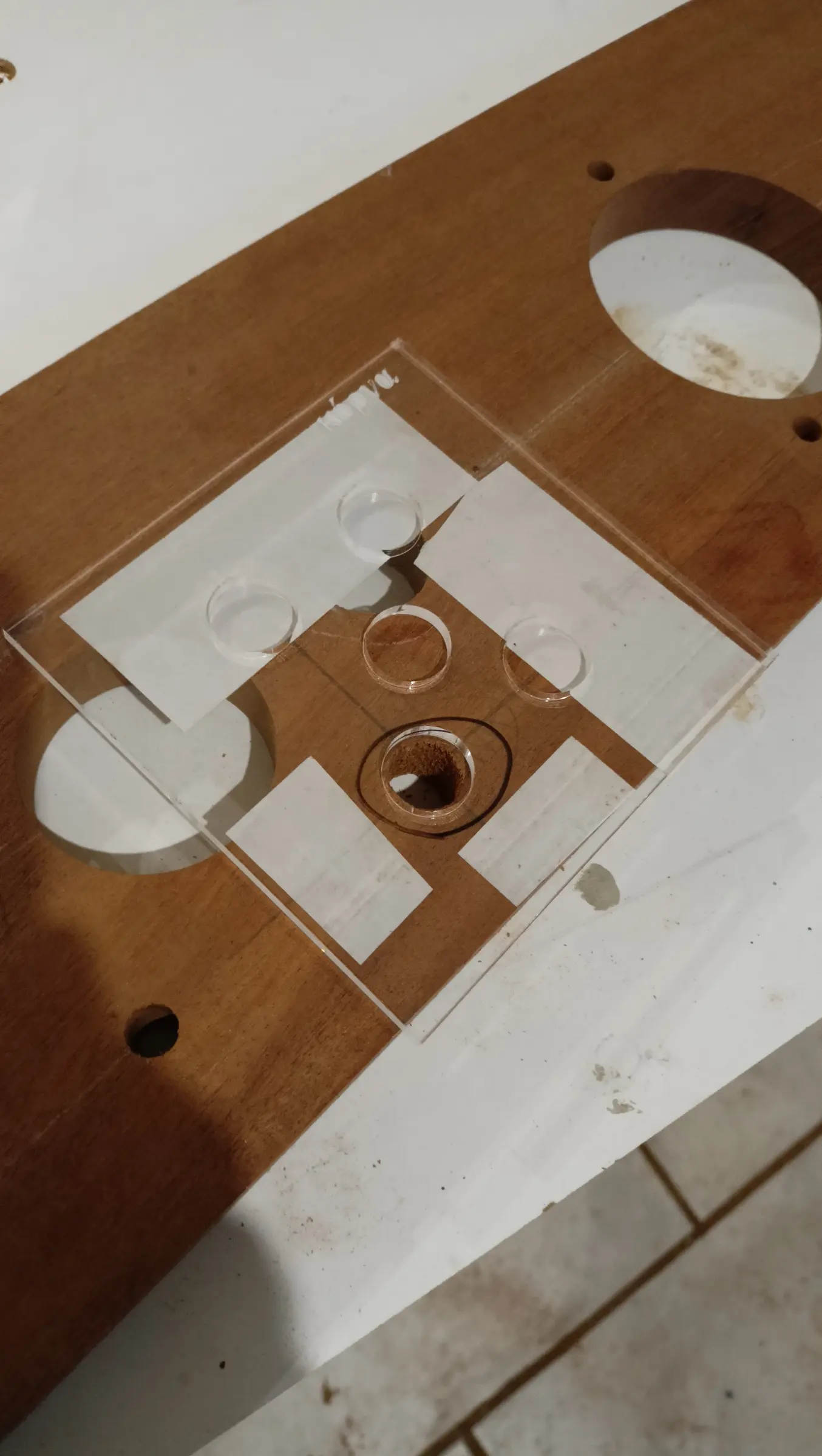
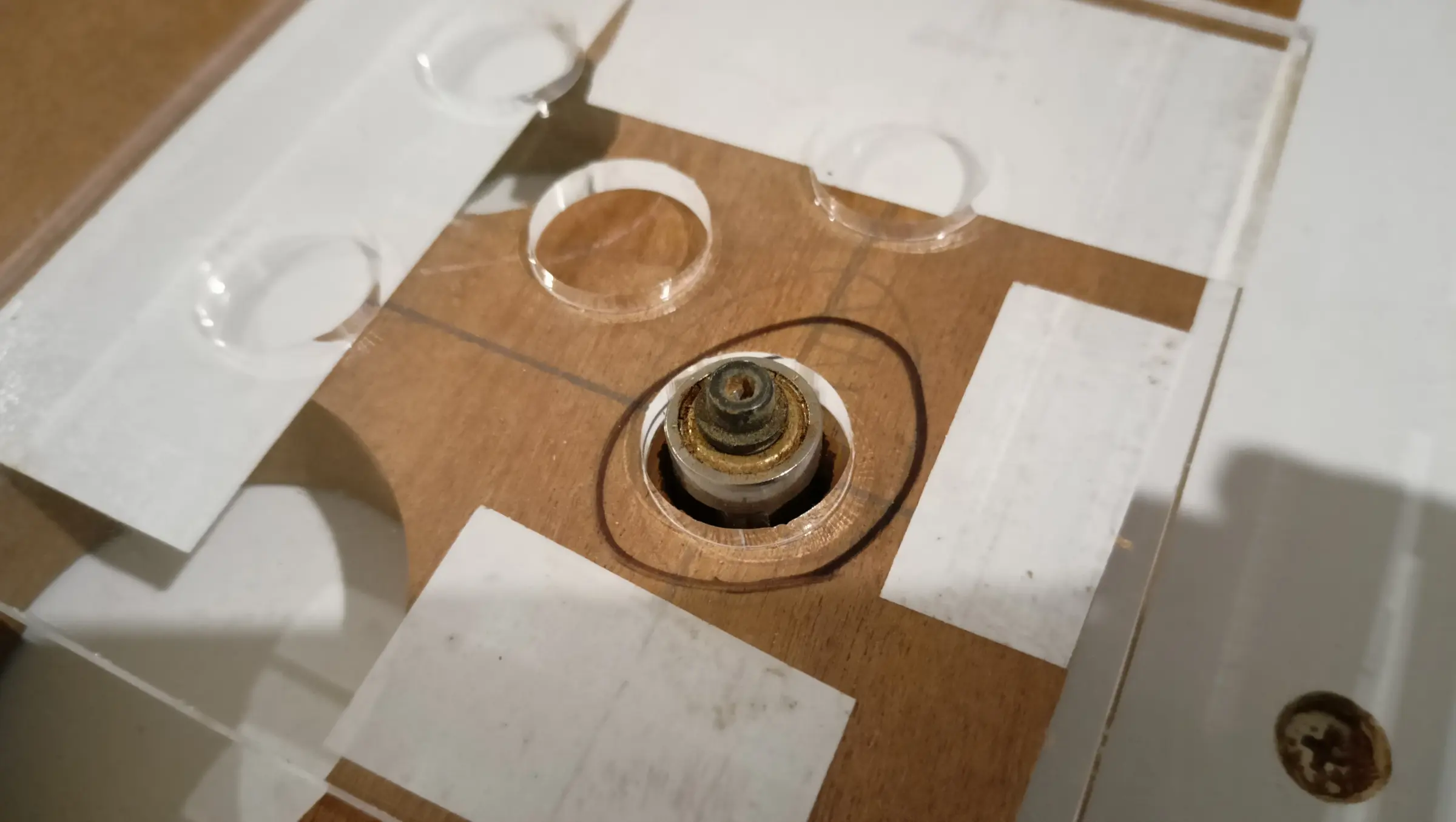
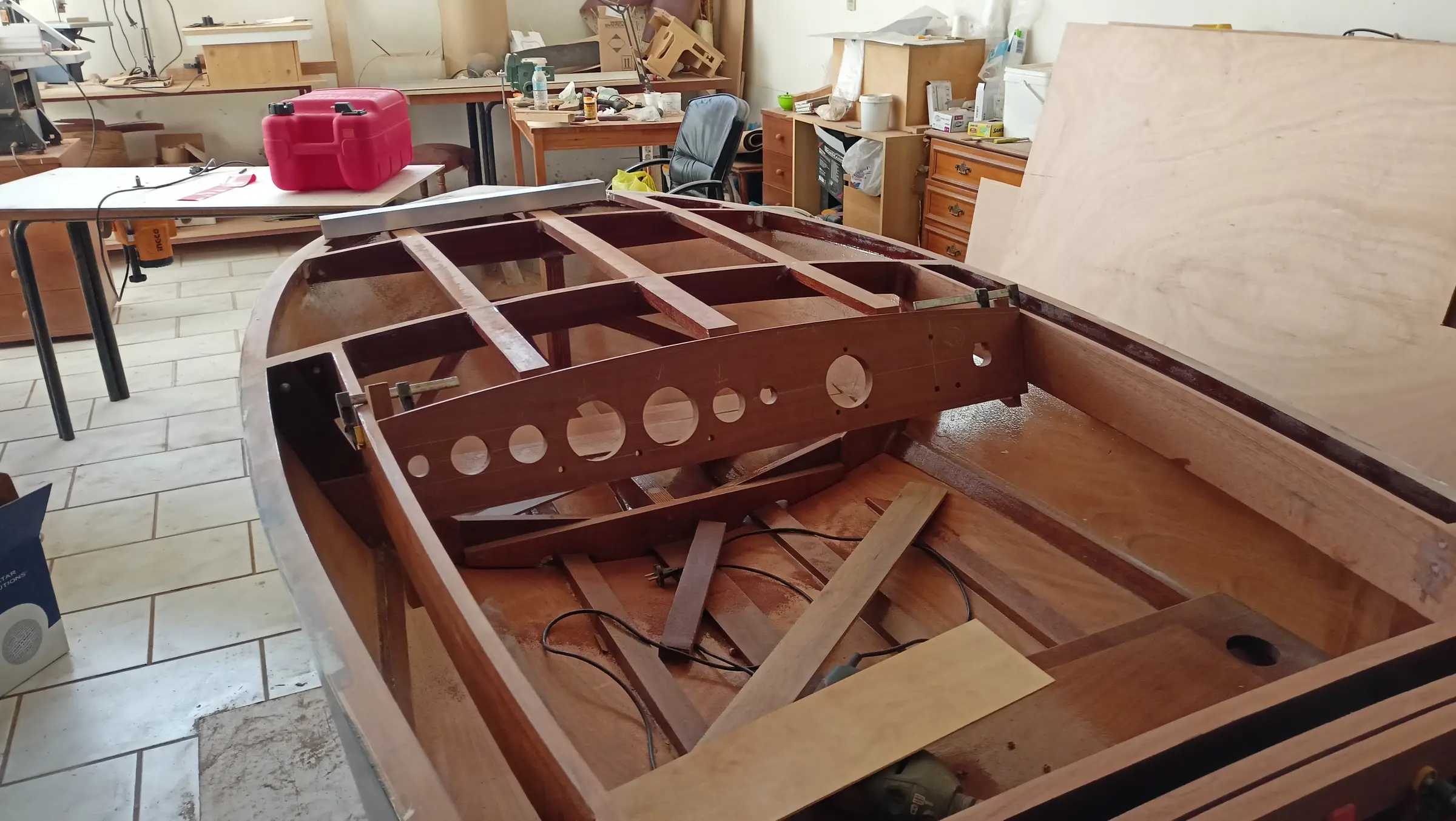
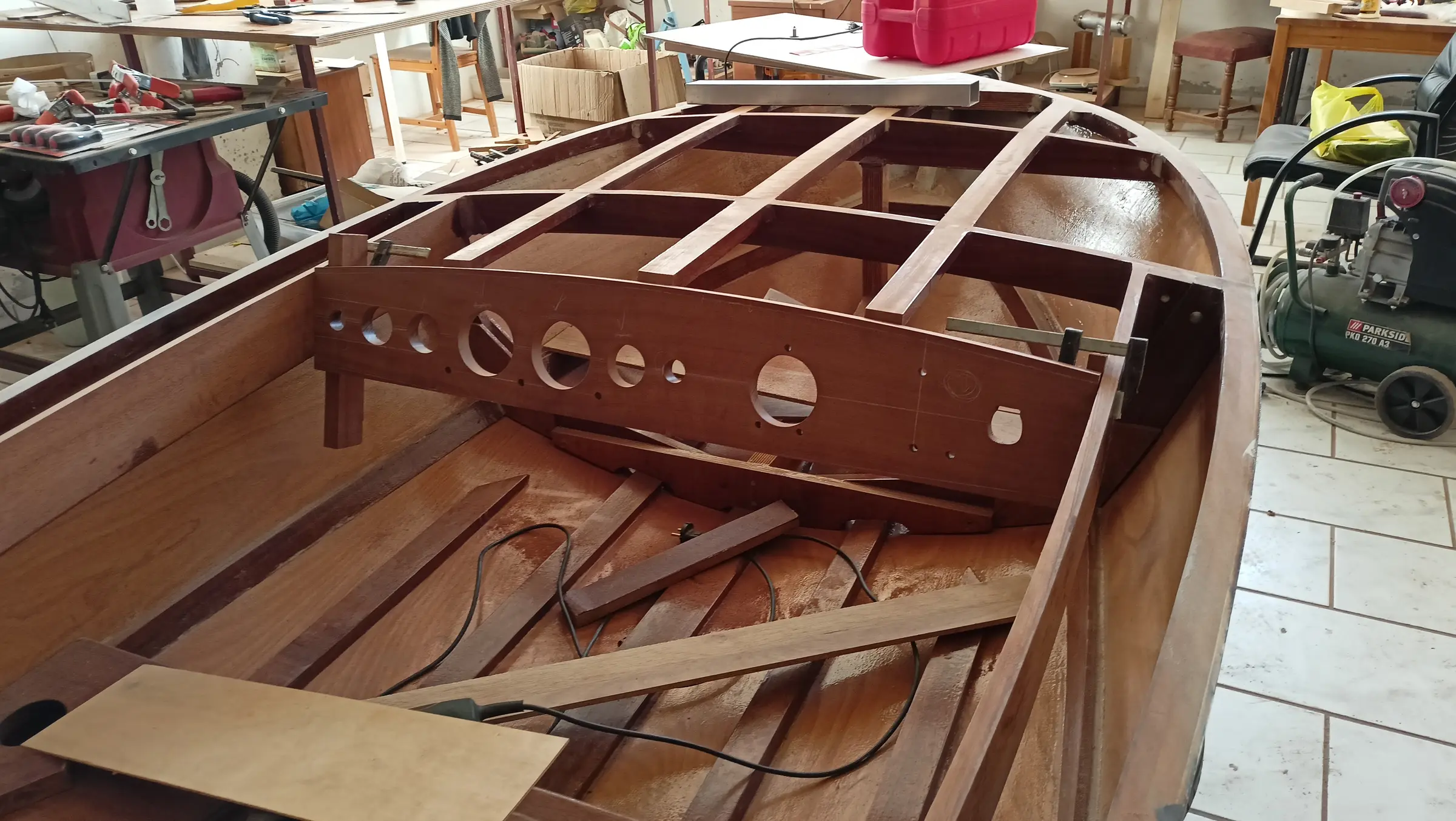
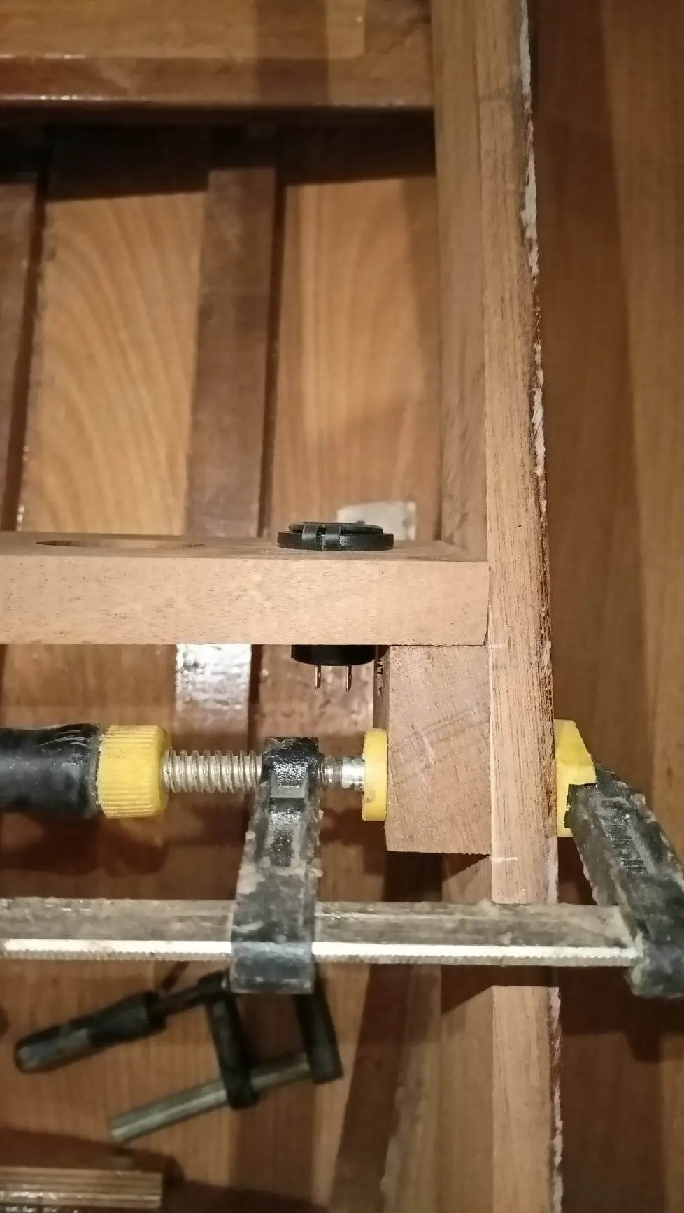
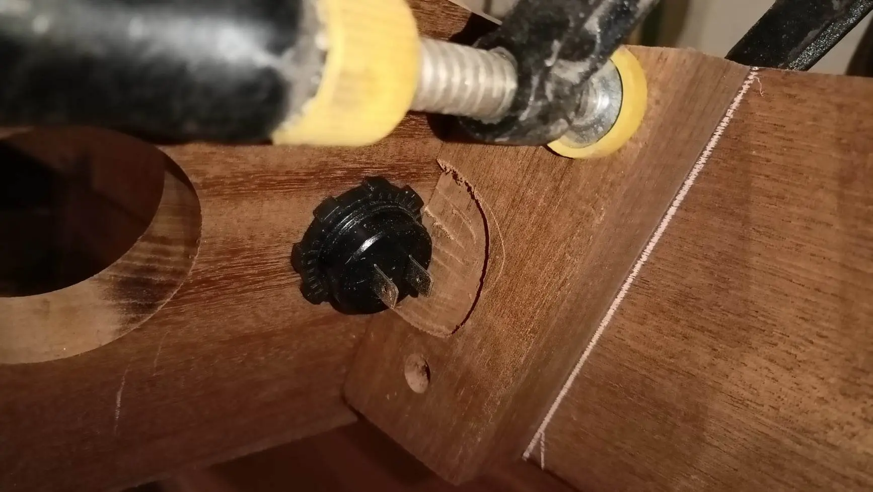
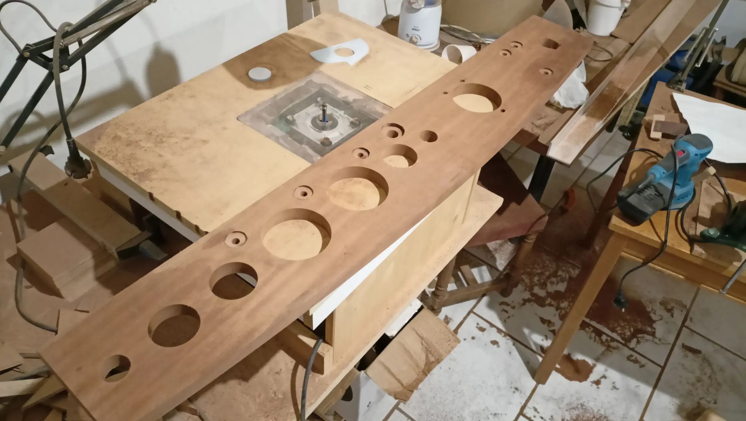
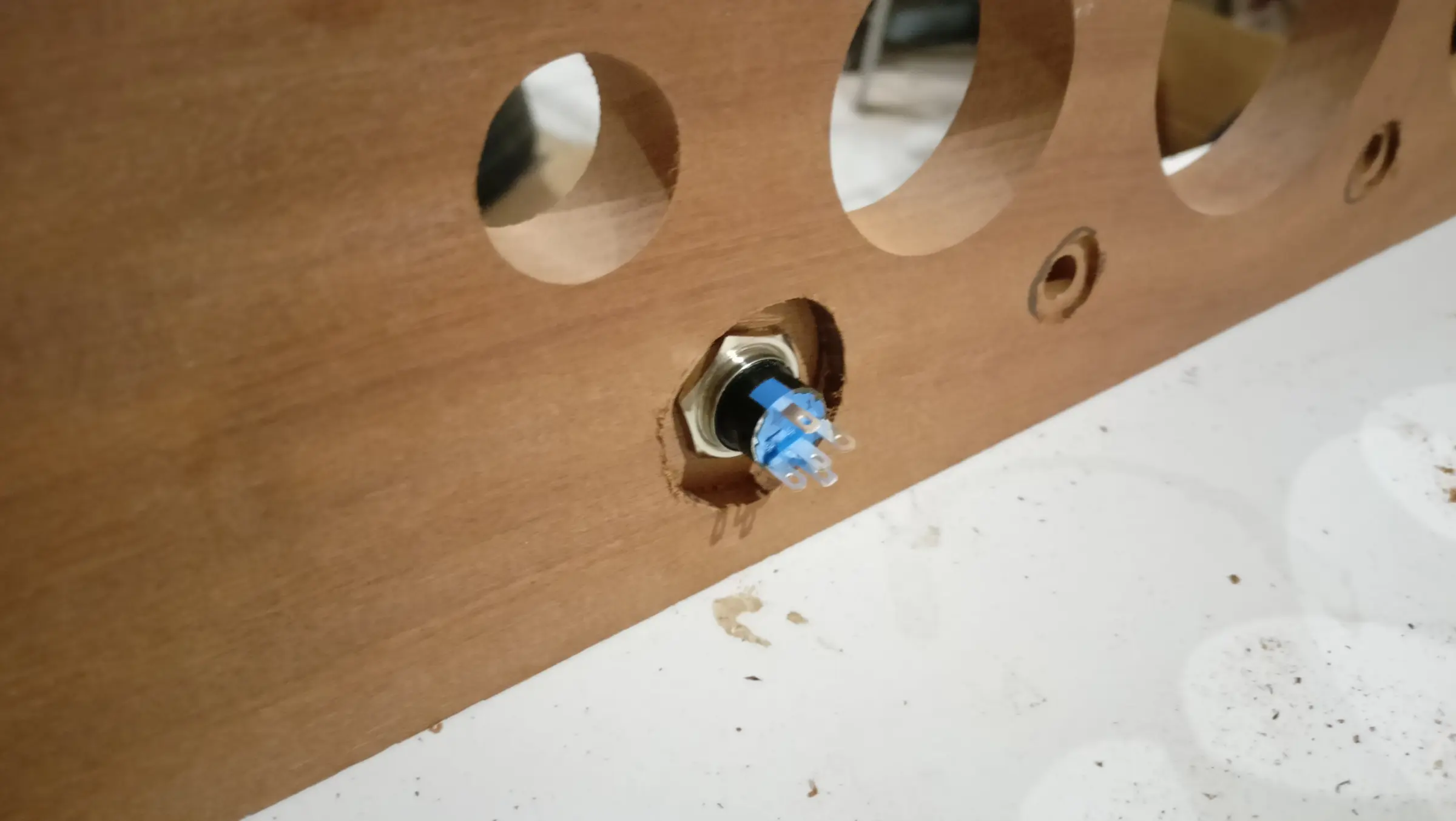
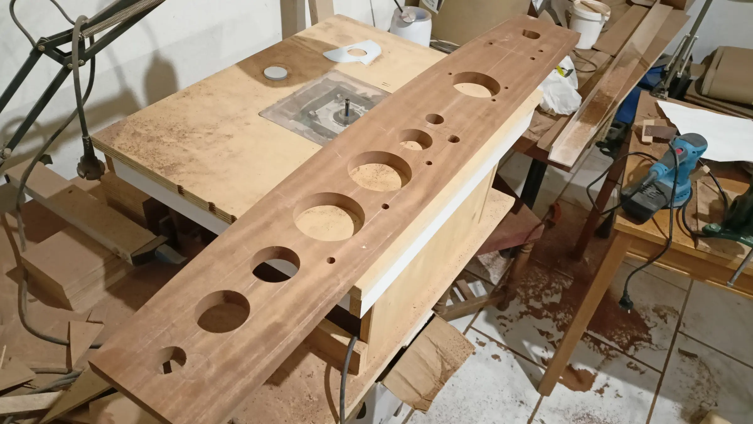
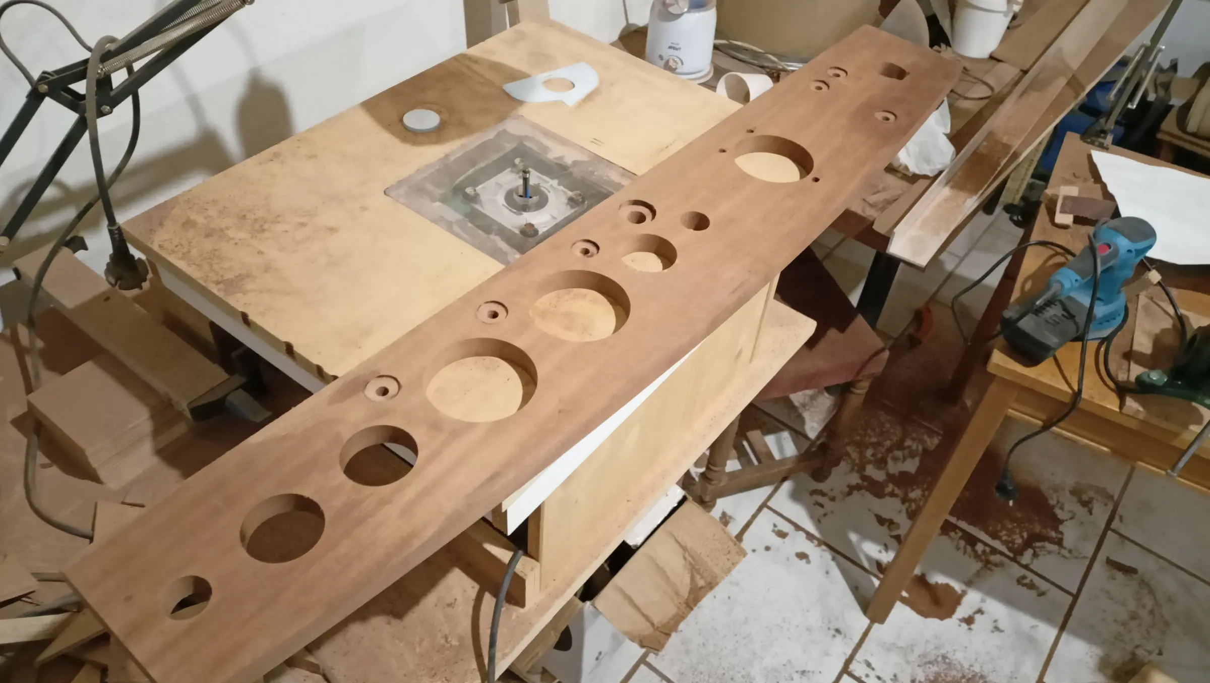
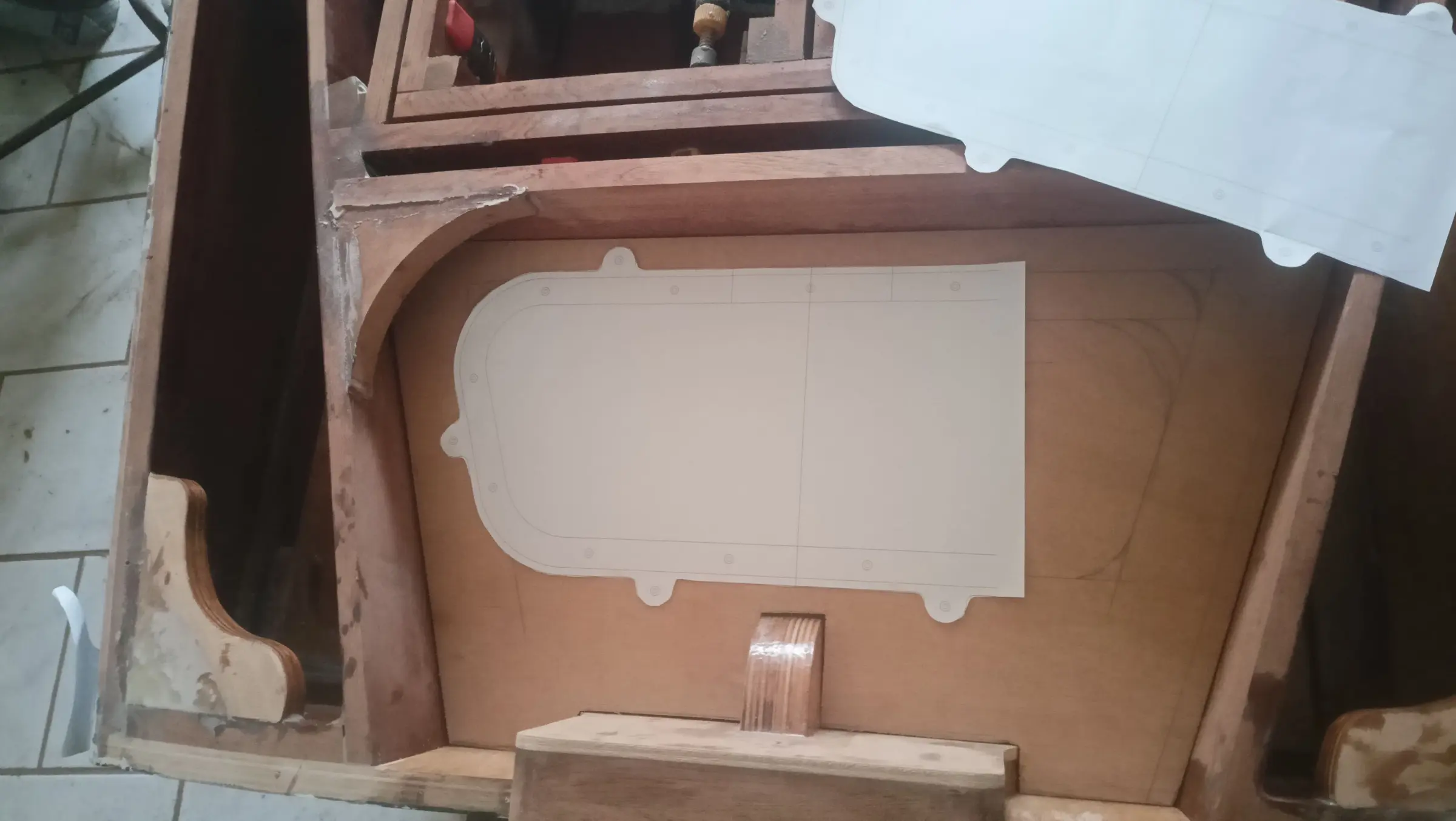
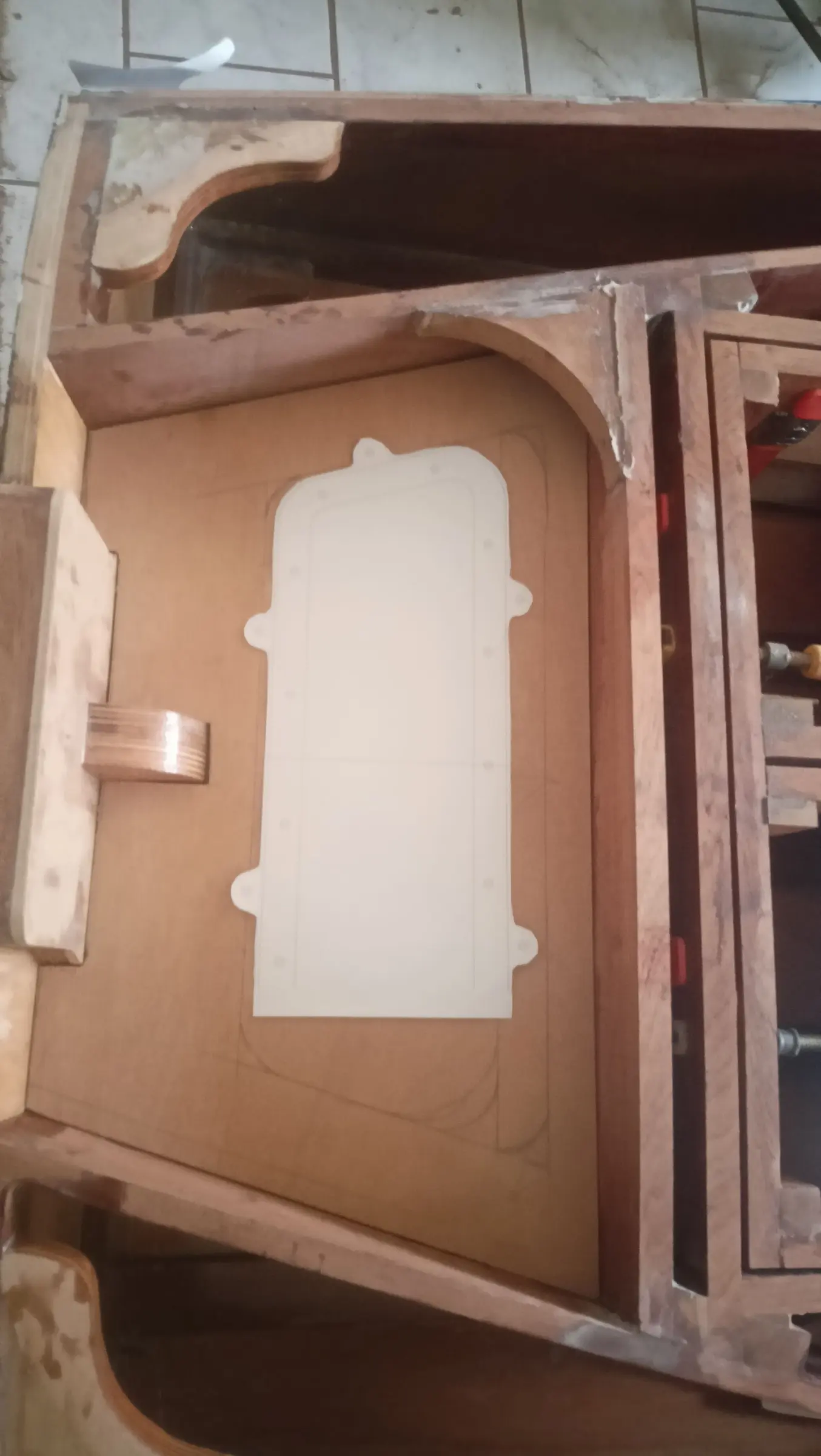
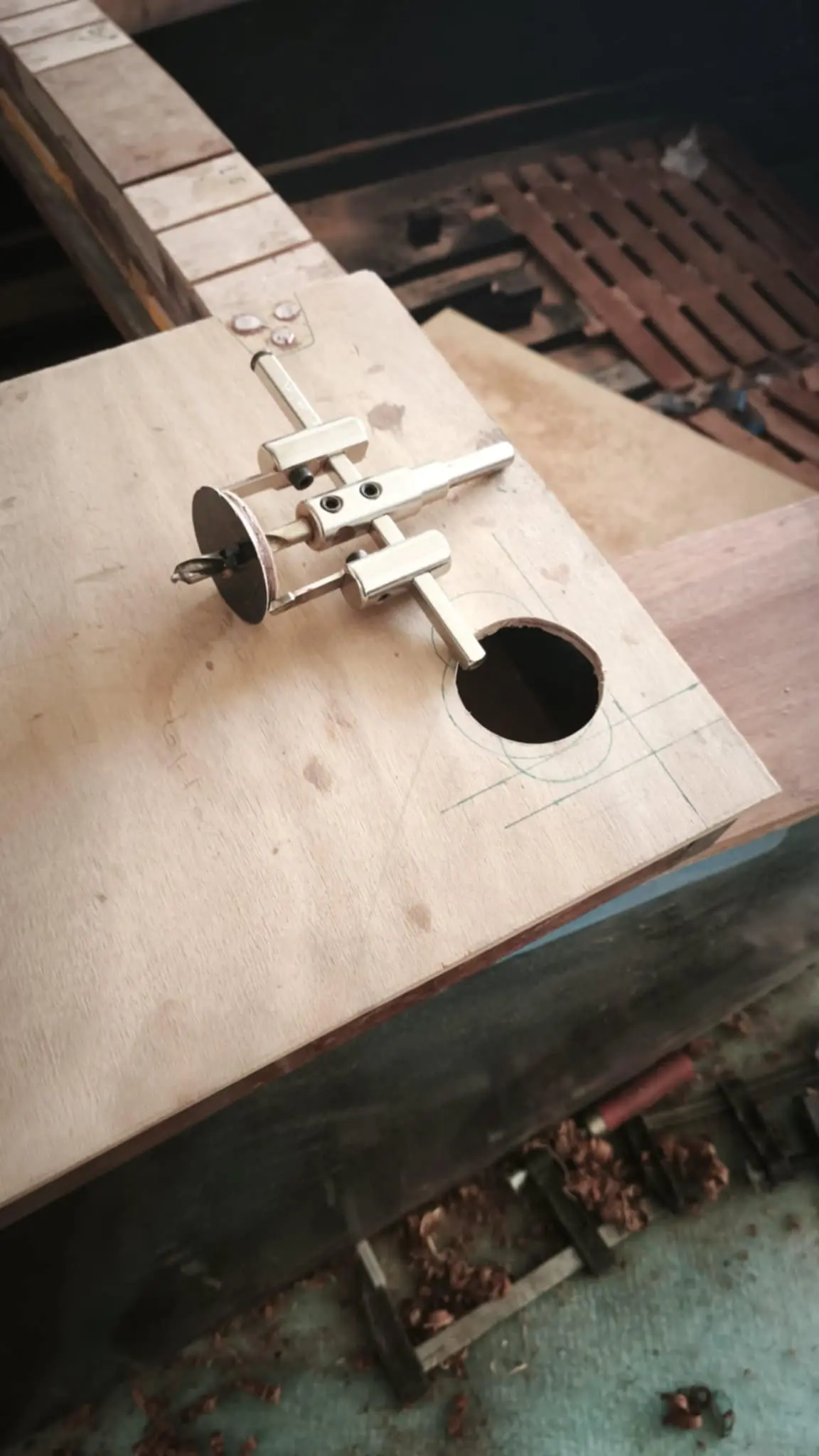
For cutting the holes, a template was laser cut so it could be finished with the router. The larger holes were cut with the tool shown in the photographs, while the smaller ones were done with a hole saw, slightly undersize. The hole saw could not manage the large ones.

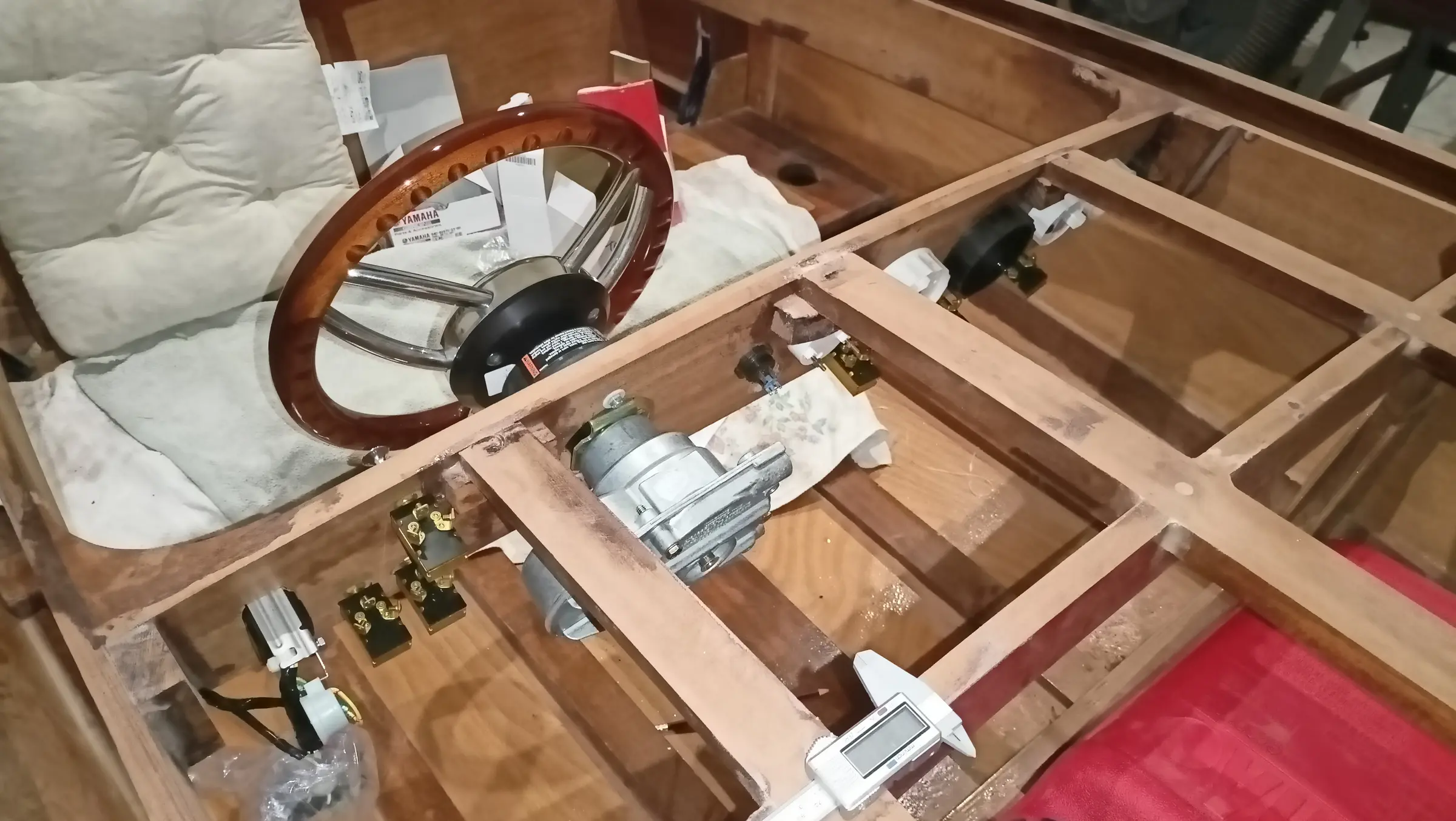
In the end I bought a mechanical steering system. It was not the higher cost of hydraulic, it was the simplicity of mechanical. I chose the SeaStar 4.2 SS147. The system is heavy duty and is used on much larger boats with engines up to 150 hp.

It was not available in Greece as a kit, but all the parts were. These are:

  1. SeaStar SSC62 TFX Quick Connect 16 ft steering cable

  2. SeaStar TFX NFB 90 degree bezel kit

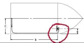
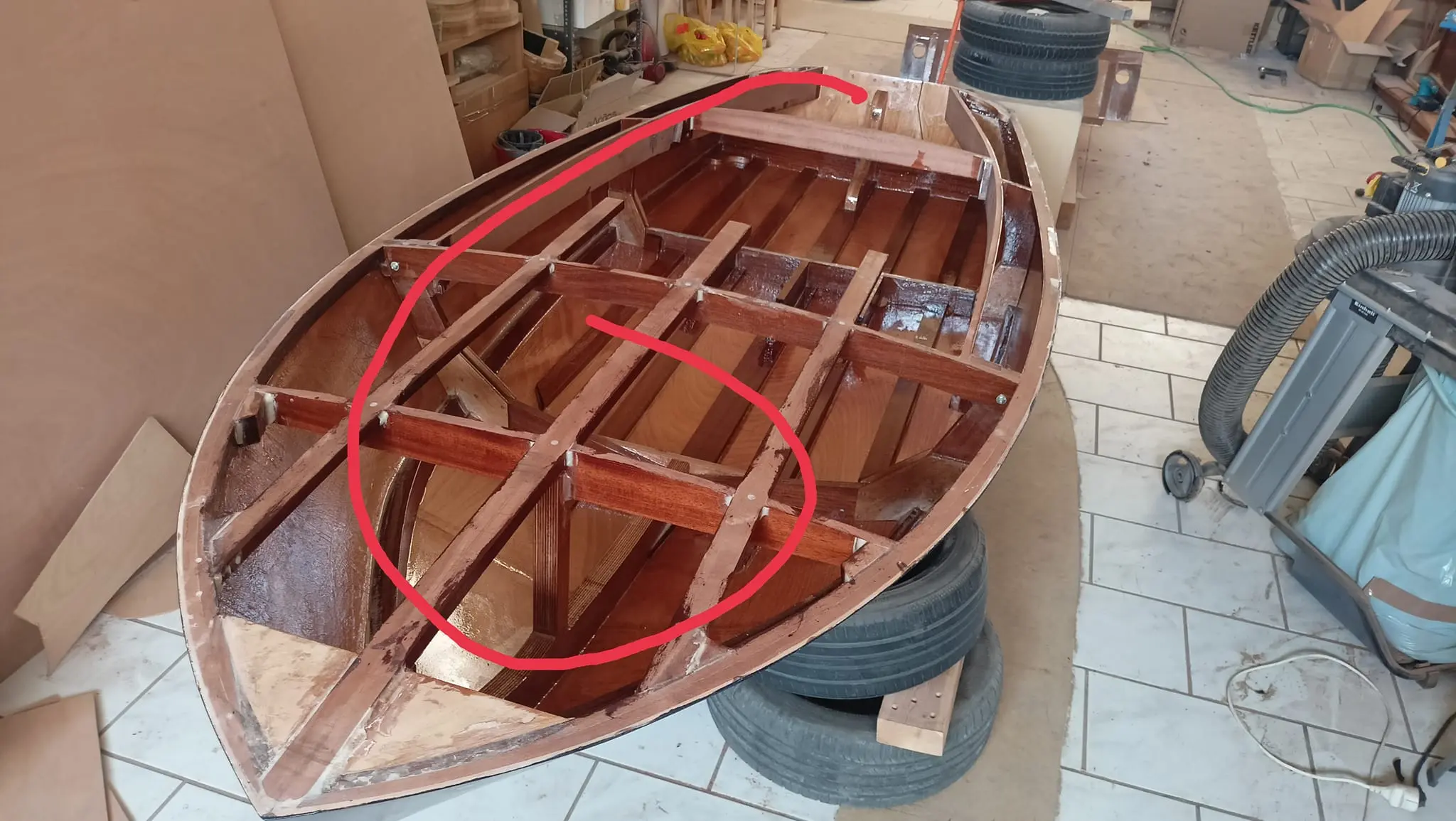
The cable I bought first was 14 feet, because it cannot take tight bends. For that reason the steering system will be mounted upside down and the cable will make a loop at the forward end of the boat. In the end 14 feet was not enough and I went to 16. To understand what I mean, look at the photograph and sketch below. The first sketch shows where the problem would have been.

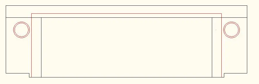
Alongside the dashboard I am also working out where the control box will go. I decided to put it lower than the coamings. So again I made a template on the laser.

The control box is a flush mount. So the mechanism will be inside and only the lever will show. It may need extra reinforcement inside and a mounting for the control box.

I have left a four centimetre margin on the top edge of the drawing so I can cut it at whatever angle is needed, so the inner part of the control box is not visible from behind (to change the mounting angle). It has three mounting positions, so there should not be a problem, but I left the margin to be sure.

The holes were cut in exactly the same way as on the dashboard.

Back to the dashboard work. Some small changes were made, since in practice I saw that some instruments were a little cramped at the back, where all the cabling will be. In the end we settled on the arrangement below.

With the bending equipment I tried to put a little curve into the three uprights the dashboard will be glued to, so they came to the right height. The test was done by offering the dashboard up temporarily to see the height they needed to come to.

Then the packers that would support the dashboard at the sides were glued onto the coamings.

On one side, because the USB will be very close to them, a little had to be taken off the inside face so its clamp could be screwed on.

Finally, because the dashboard is thick for fitting the switches and the horn, its thickness was reduced slightly with the router.

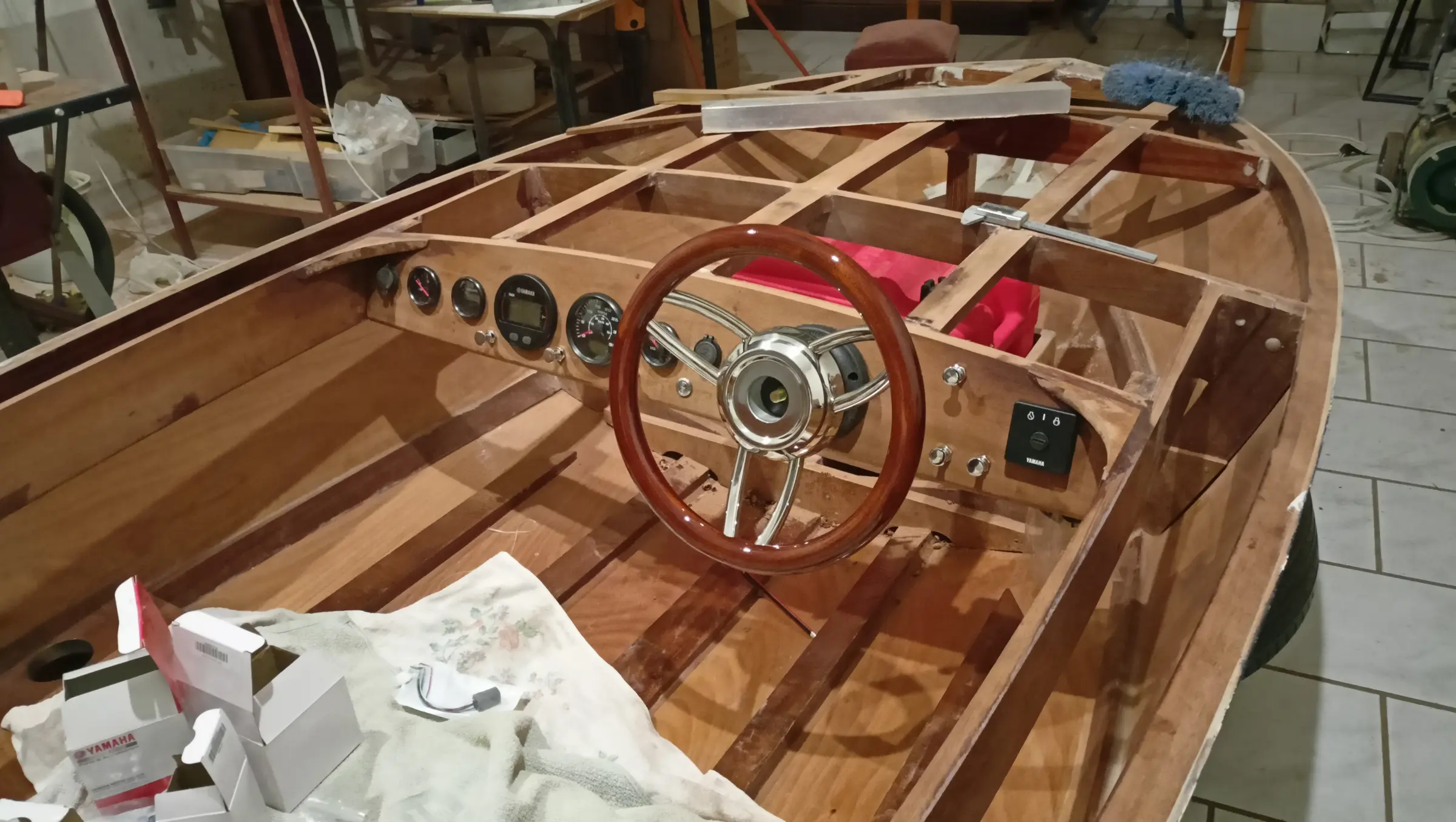
The final instrument layout on the dashboard is below.

The next job is routing the curve on the lower edge of the dashboard so that at the ends its width matches the width of the coamings, rounding it over, and then gluing the dashboard onto the coamings.

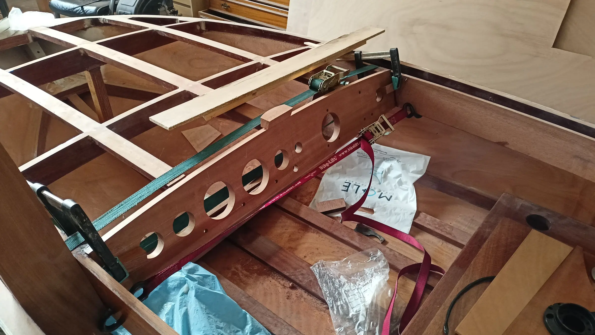
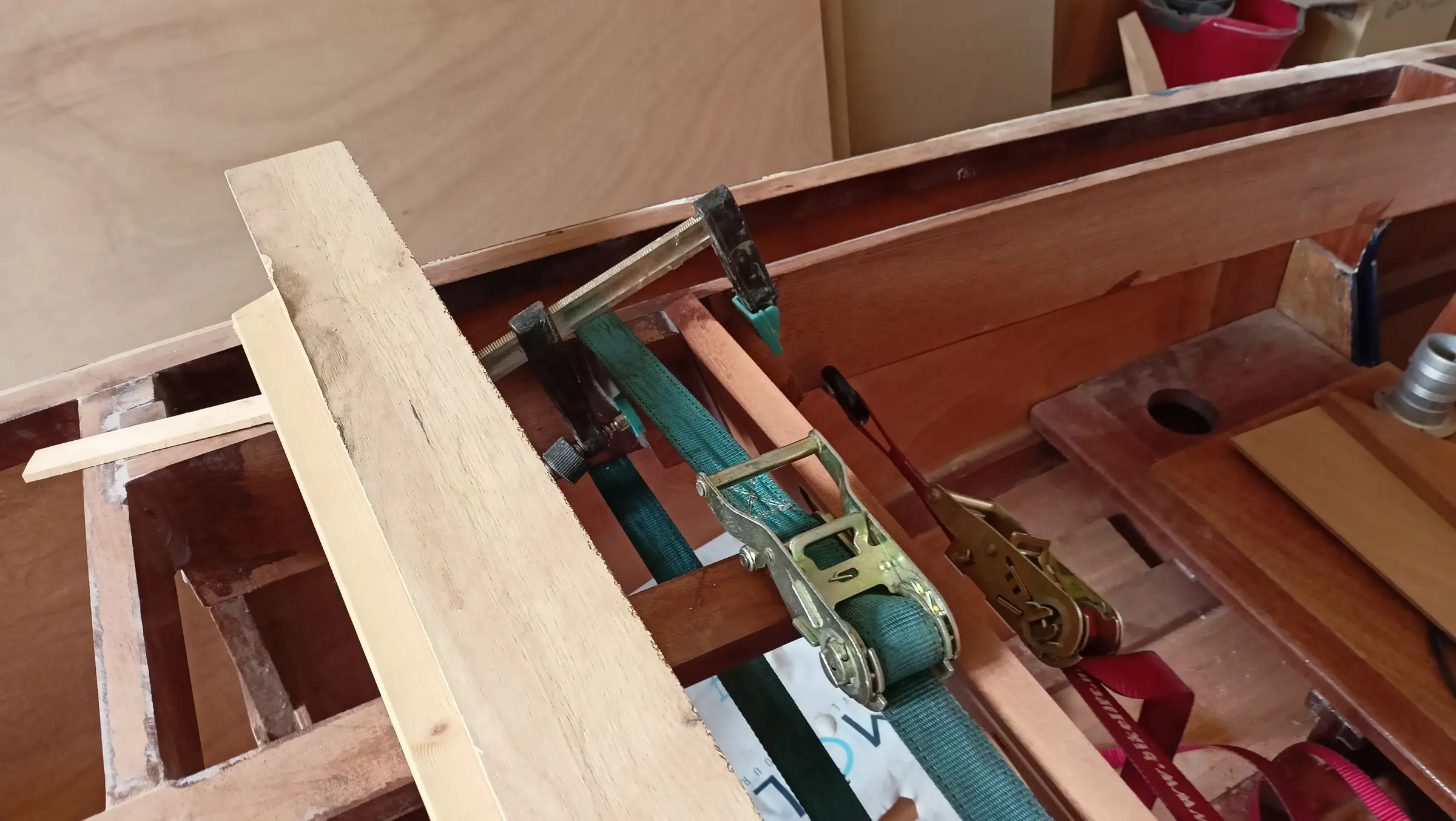
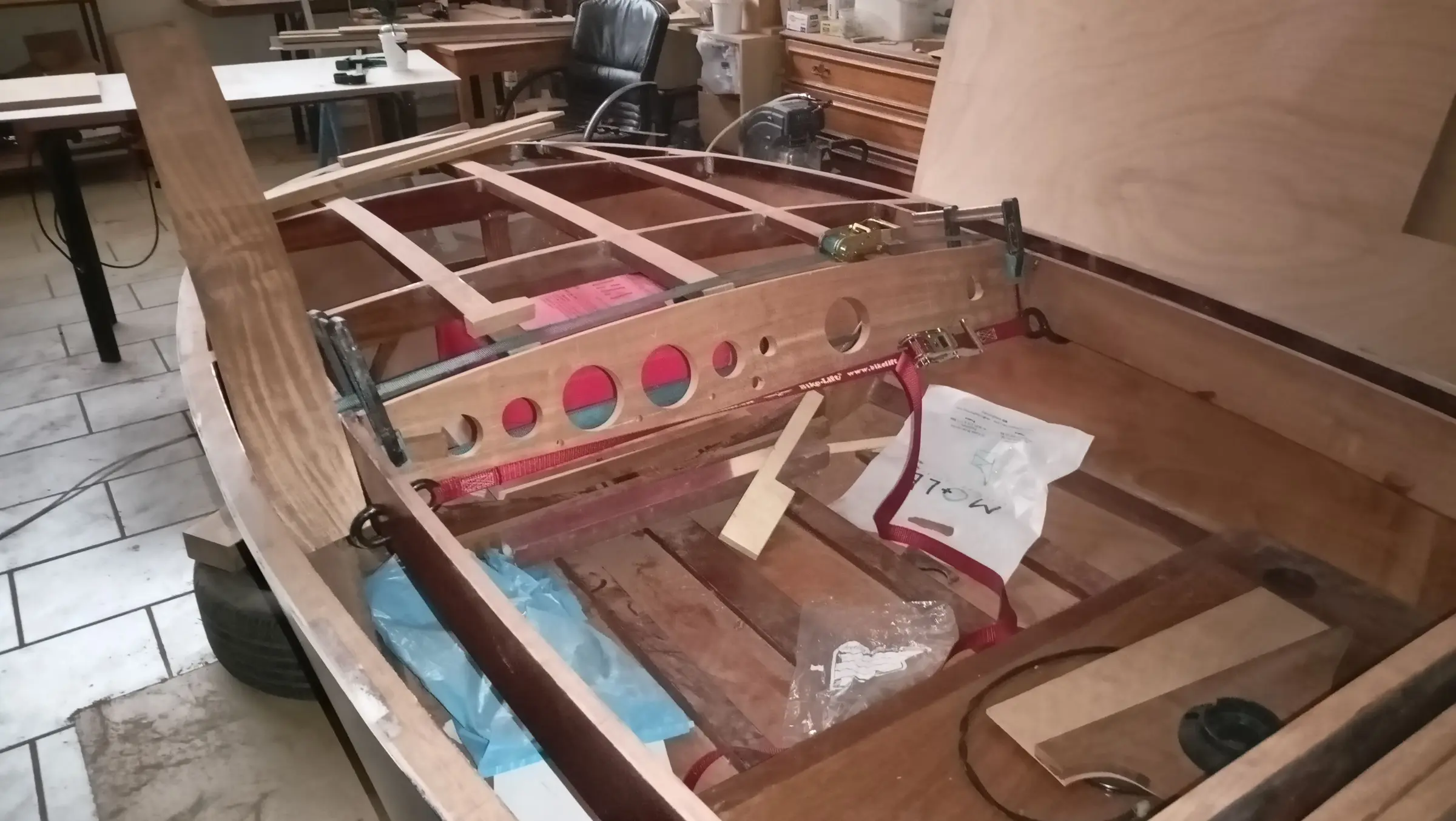
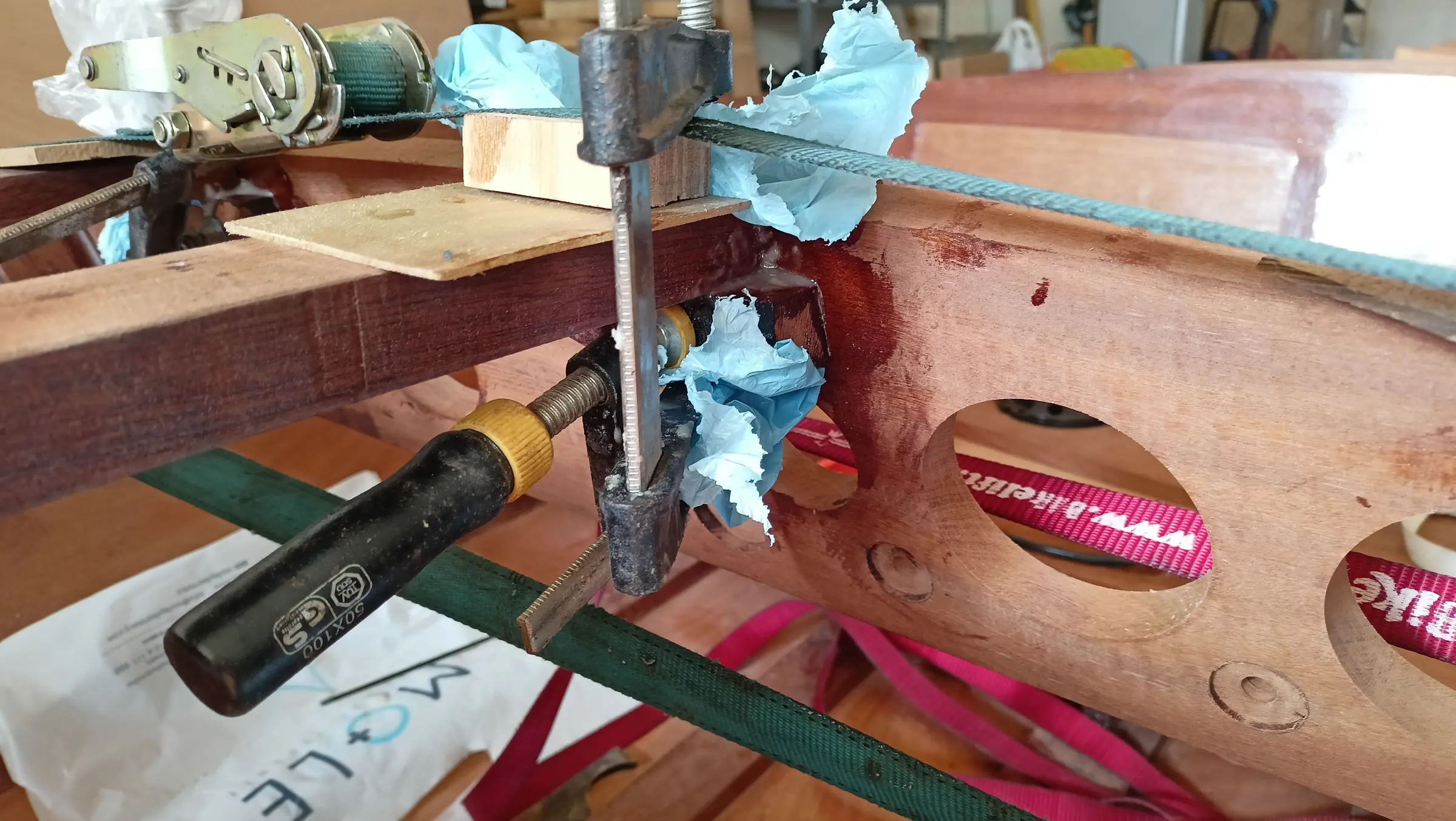
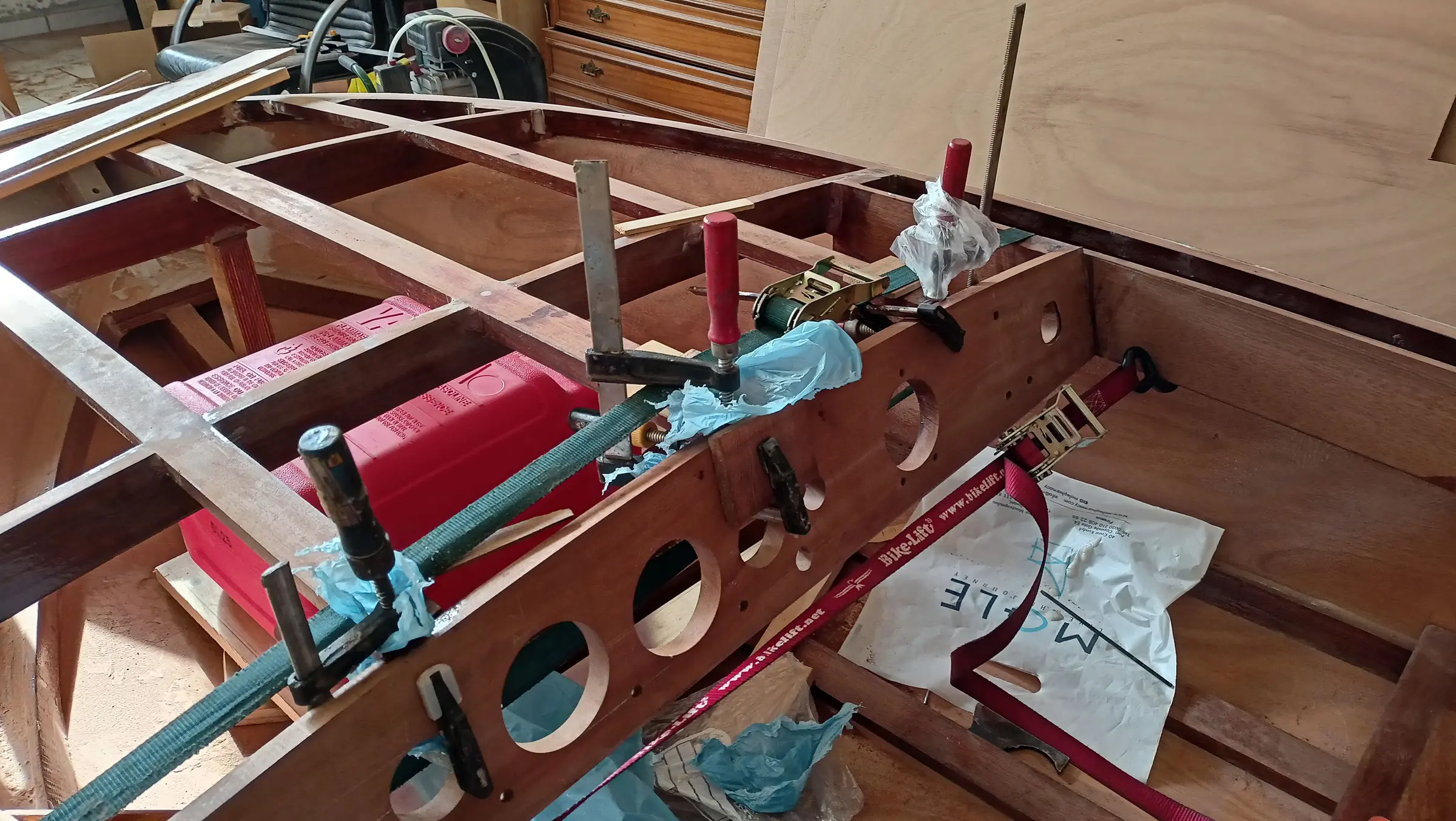
For the glue-up, straps were used as well as clamps, so as to close up the smallest gap that might be there.

The red strap was used for the gap, while the green one helped bring the three athwartships pieces down to the right height.

It was glued to the coamings first and then to the three athwartships pieces, so it went into its exact position.

Those were then glued as well, after first making blocks so they bedded properly against the dashboard. The photographs of the work are below.

Then the curved pieces were made that join the dashboard to the coamings, which the plywood will sit on, for the look of it. The difficulty in making them is that angles have to be cut on the two inner faces so they can be glued.

The last job for the dashboard was gluing those in. Because underneath them there is the engine key on one side and the USB on the other, I took their thickness down a little so they would fit. The curve was cut to a 23 cm radius and they were glued on.


The numbers: hours worked and cost

Some figures from the build.

The full breakdown of hours and costs is in two spreadsheets on the original blog:

Hours and costs, part 1

Hours and costs, part 2


Interior work No. 4

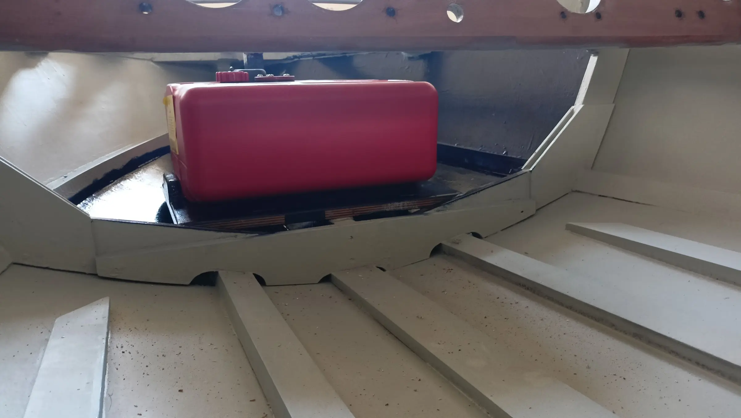
The first job was building the base for the fuel tank.

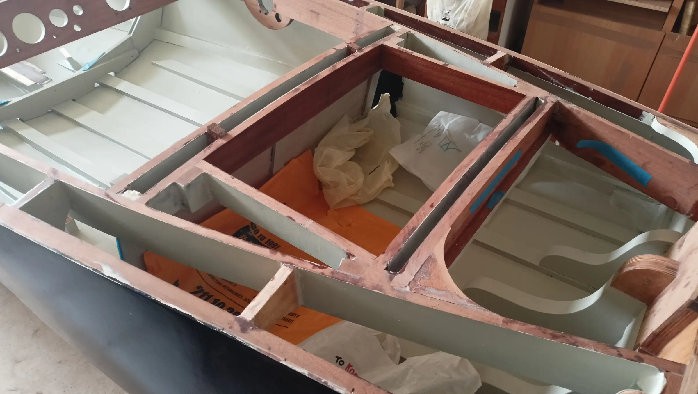
As mentioned, it was decided in the end to install it in the forward part of the boat. To fit it, a box will have to be built that sits on the keel. The tank will be modified as needed to provide venting, a fuel level sender, and a filler cap on the deck. I looked for a small tank for permanent installation with the fittings already in it, but the smallest I found was 36 litres. So I decided to modify the one that came with the outboard, which is 24 litres. First the surface the tank box would sit on had to be made flat. To do that, timber and plywood of suitable lengths were glued onto the keel and then the gaps were filled with resin.

The box the tank goes inside will be glued on top of those. Industrial rubber mounts will be glued inside the box to absorb vibration.

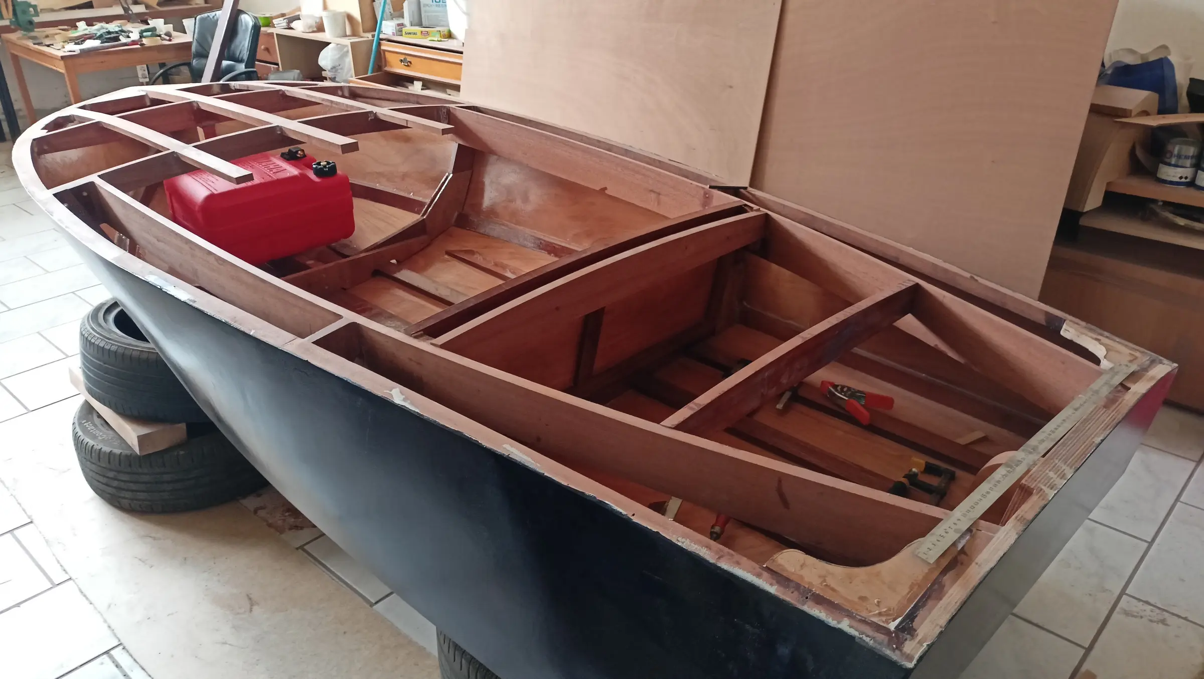
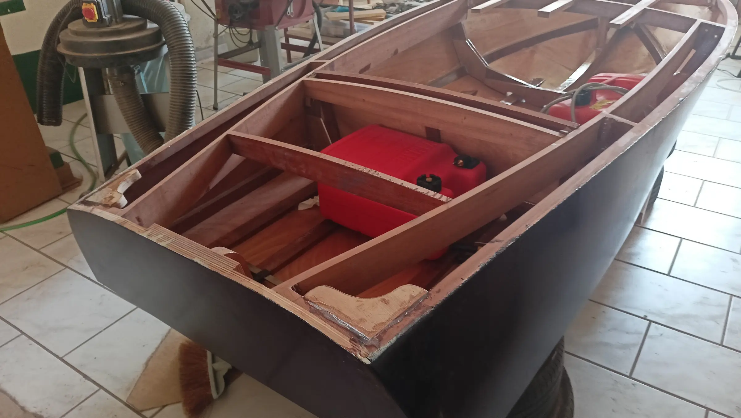
Once it was built, it was offered up in position and I found that if I ever wanted to take it out I would struggle, as it only just passes under the dashboard. So I decided to reduce the height of the forward upright. Below is how it ended up.

Various other jobs are going on at the same time.

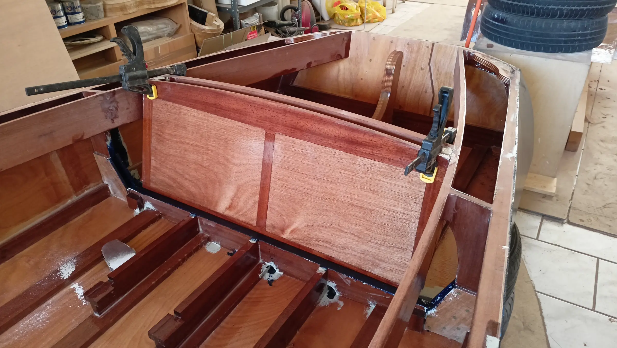
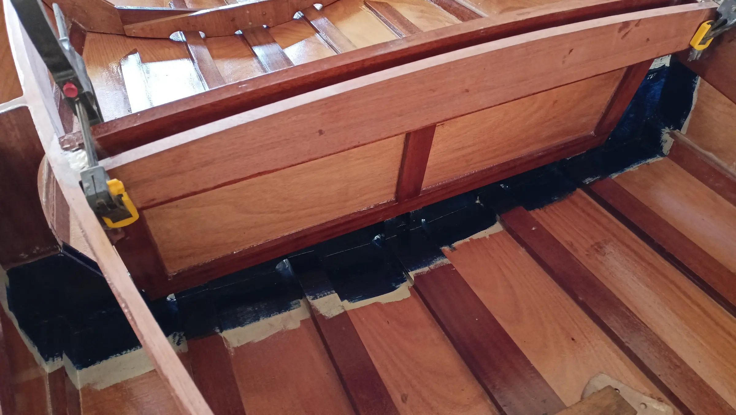
One of them is gluing in the inner timbers of the locker. In the end it was decided to have two doors, one on the left and one on the right, so there is easy access to the engine. The gap between the two pieces was worked out at 6 millimetres so they can open without one fouling the other. All the gluing was done with the locker clamped up, so I did not lose the curves.

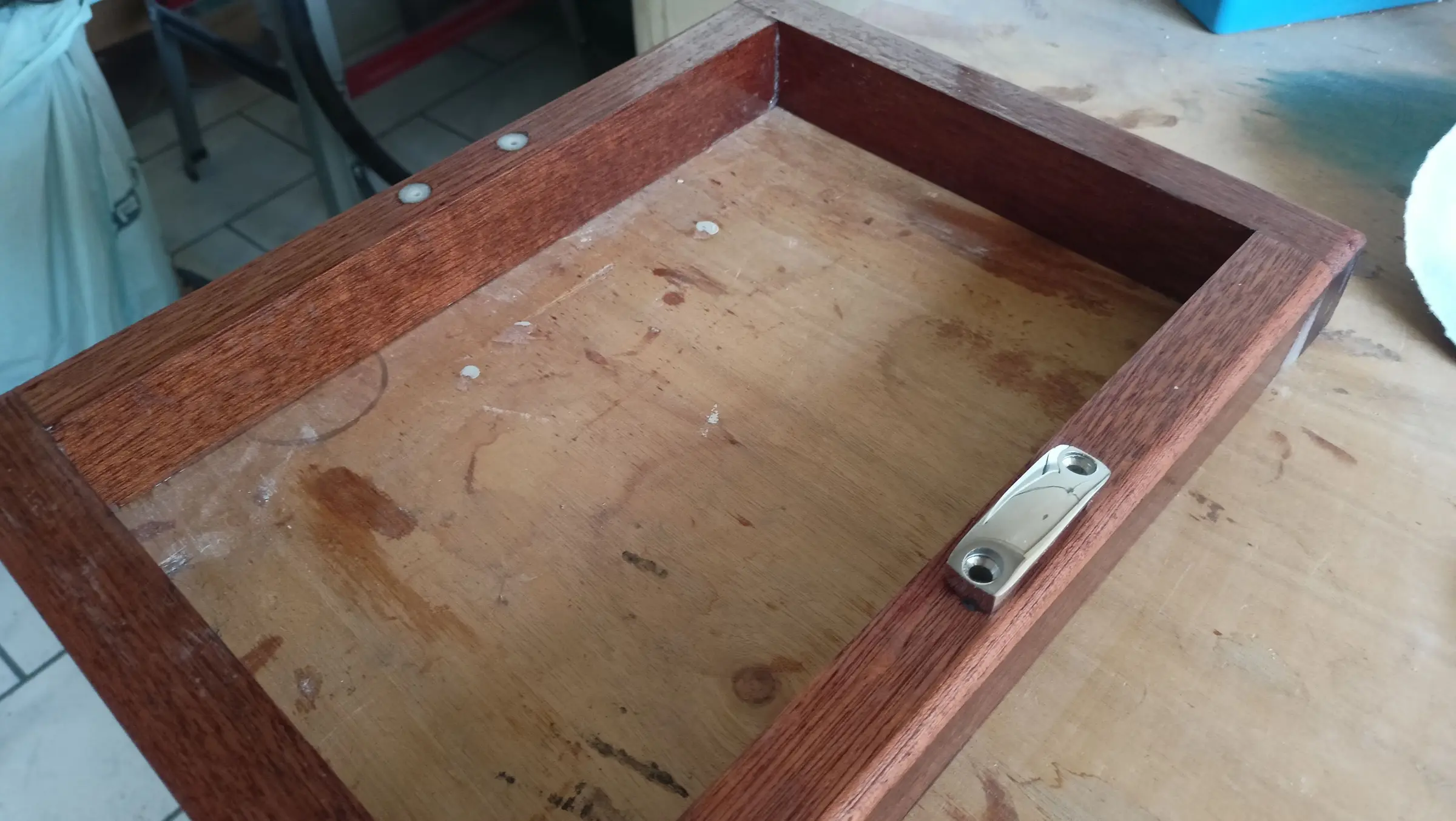
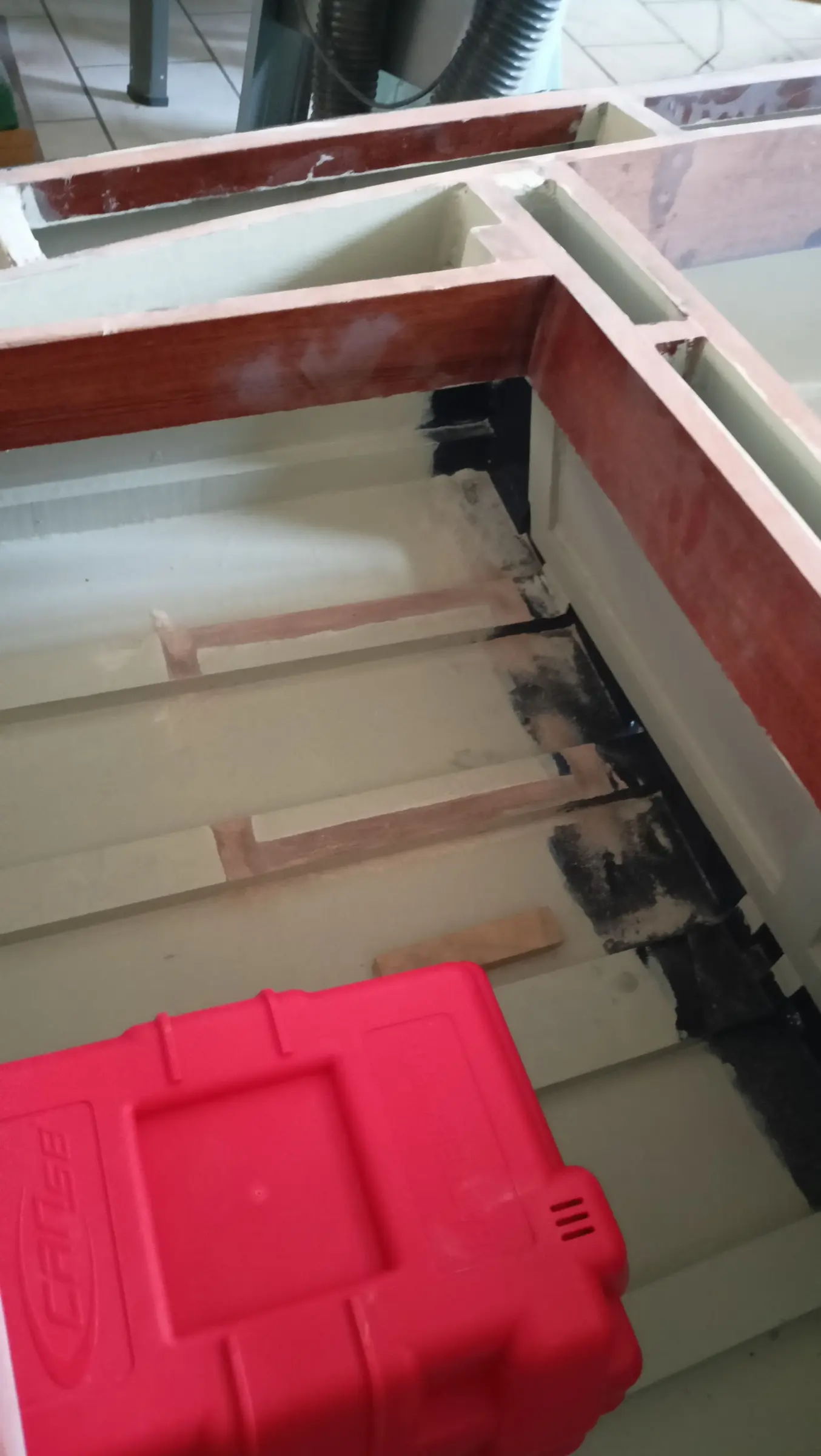
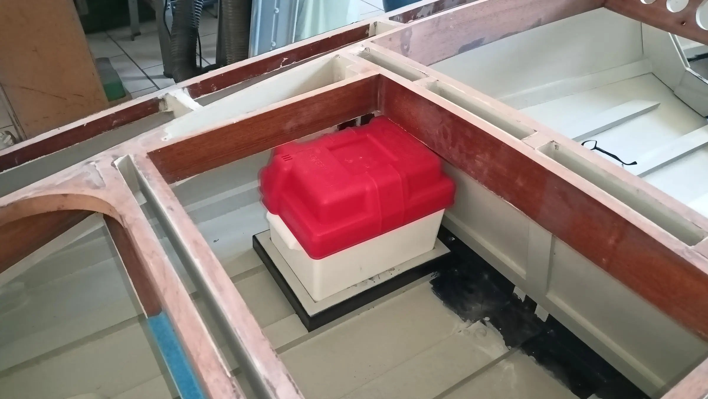
Another job is building a box for the boat's battery. A lithium battery will be chosen to keep the weight to a minimum (the arrangement changed, see the photographs in Interior work No. 5).

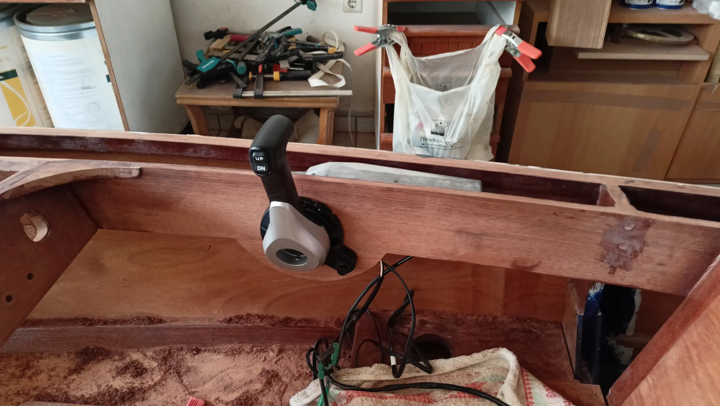
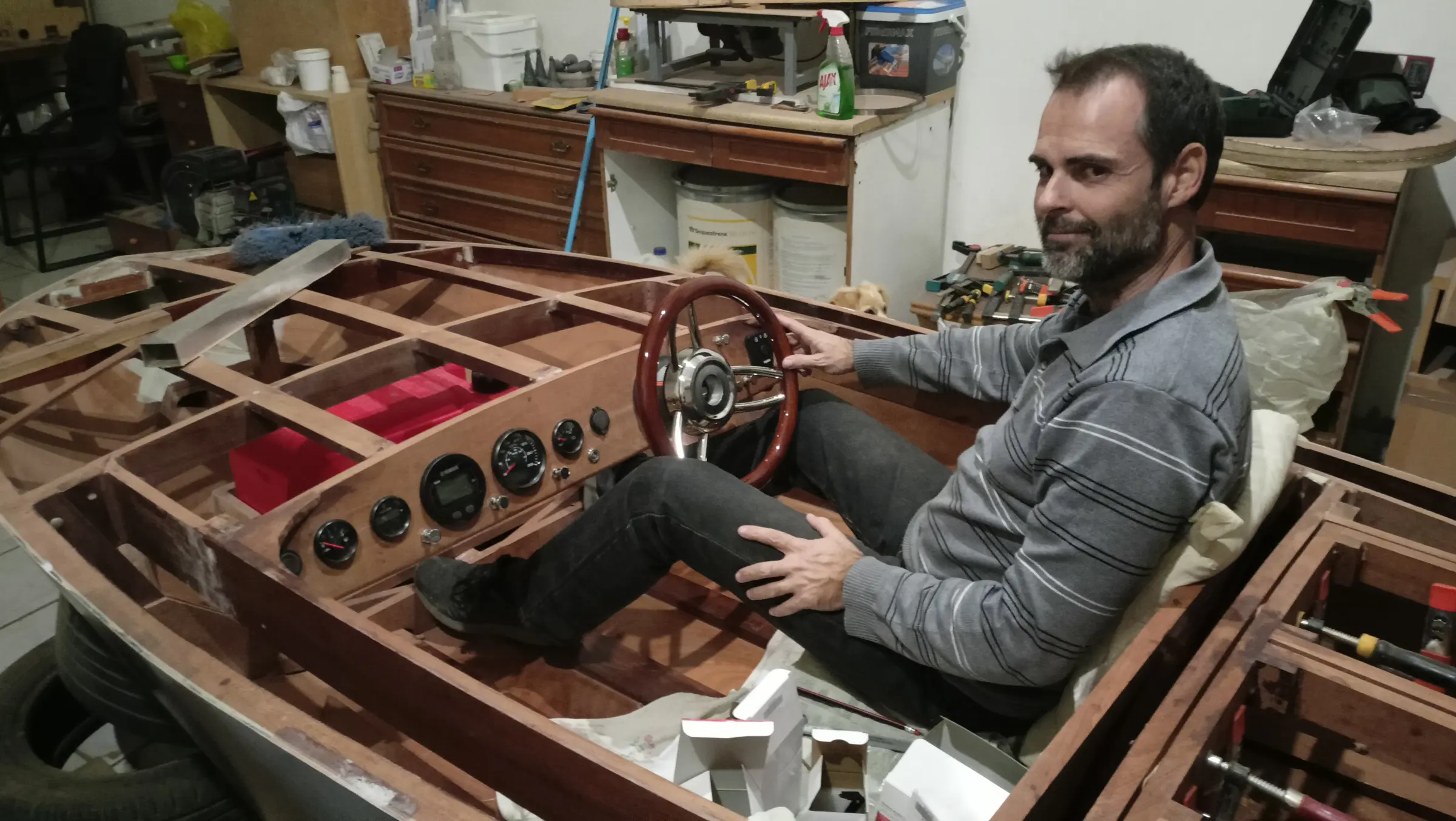
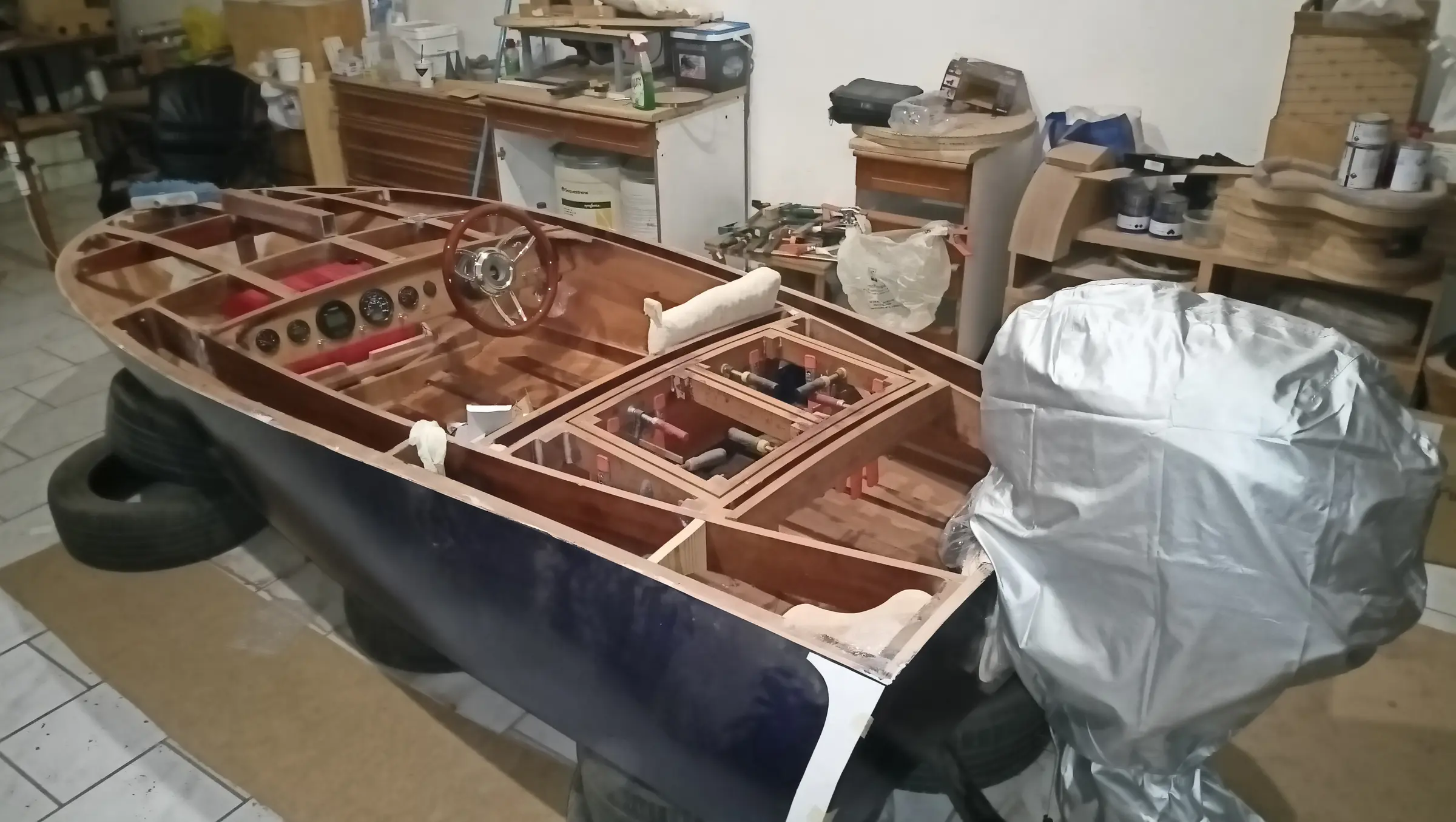
The next job is fitting the control box. To find the best position I temporarily put cushions on the seat so I would be sitting as close as possible to the right position, and tried where the control box suited me. I found it would have to be mounted on top of the coamings and not underneath, as I had worked out and made the packing piece for. So the hole shown in the photographs was cut. Three quarters of the hole is in the coaming and the rest in the packing piece, which was shaped to match. That is so the boat's framework does not lose strength.

Behind the coaming, because a fair amount of wood was removed, a 6 mm plywood reinforcement was glued in.


Electrical work and the rest of the wiring

Alongside the interior work I am also getting on with the electrical installation. The cable being used is tinned, made specifically for use in a marine environment.

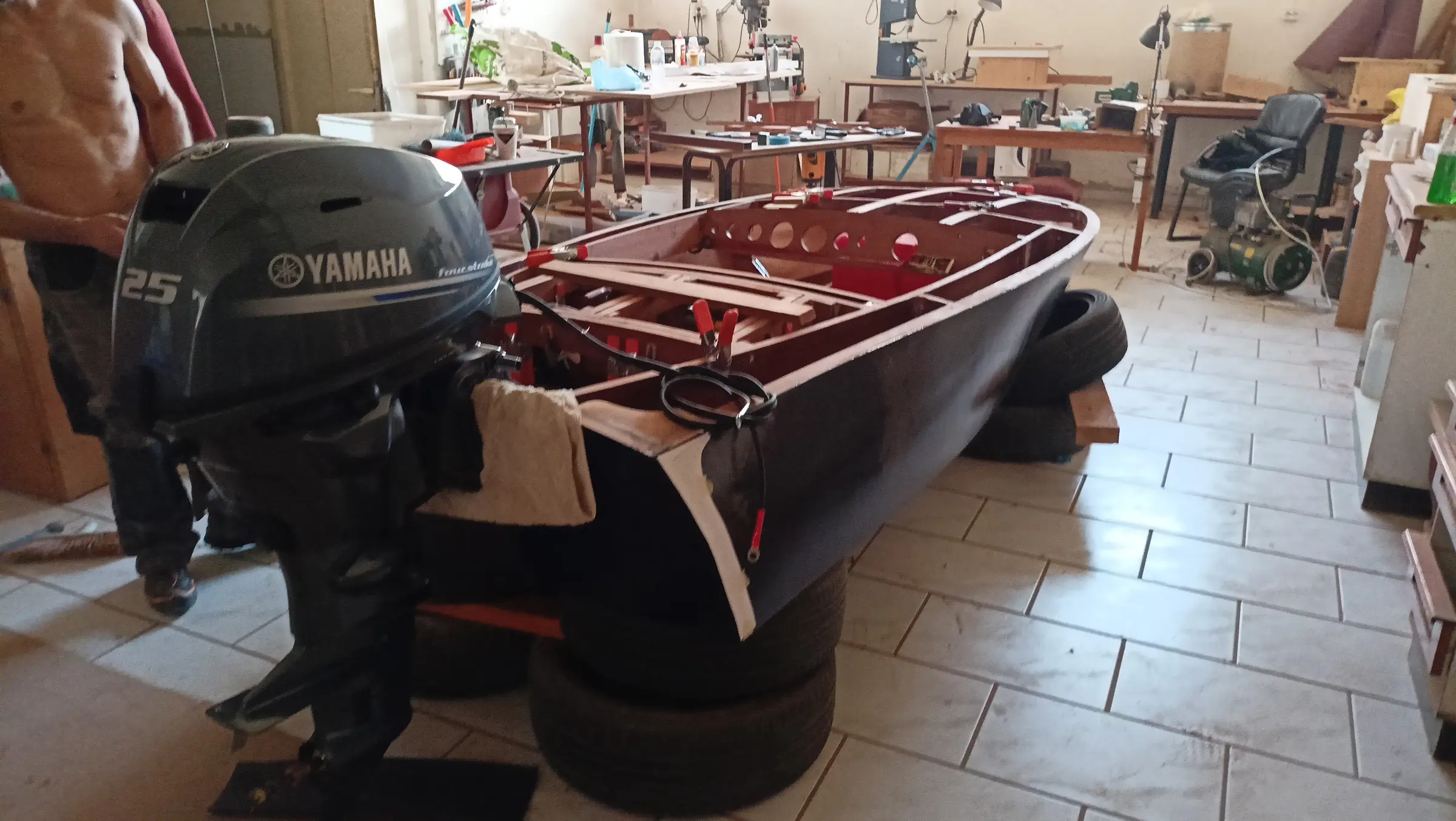
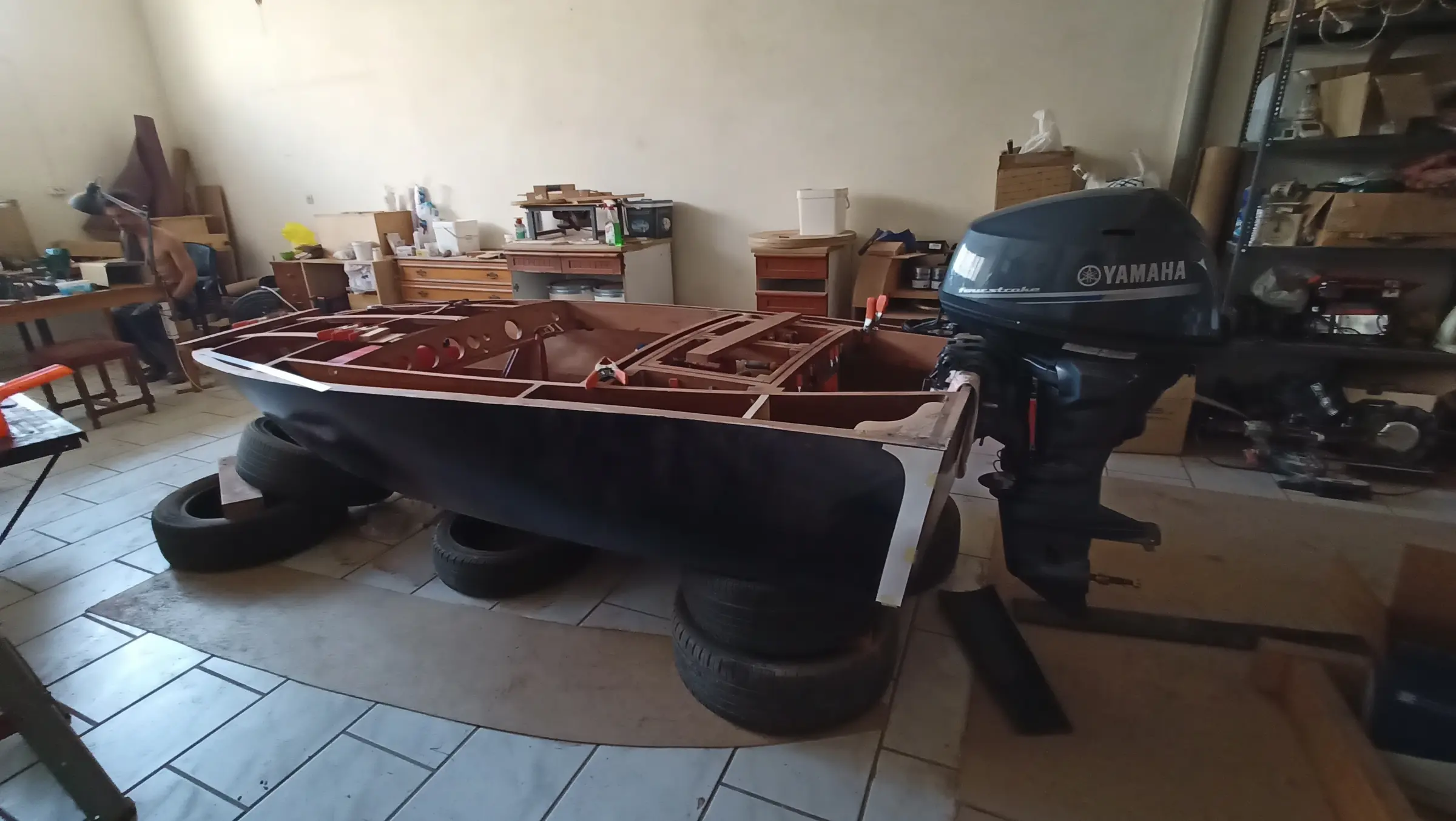
To work out the routes and the cable lengths, I fitted the outboard onto the boat.

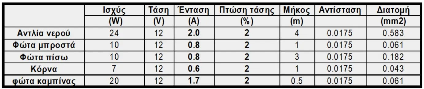
Cable cross-section is calculated on the basis of the maximum acceptable voltage drop, which should not exceed 3 to 4%.

For a greater margin I set the maximum acceptable drop in the spreadsheet at 2%.

Voltage drop for a DC circuit is calculated with the formula:

dU = p * (L / S) * (P / V) <= 2%, where p is the resistivity of the conductor, L the length in metres, W the load in watts, S the cross-section of the conductor in mm2, and V the voltage of the circuit, which in our case is 12 volts.

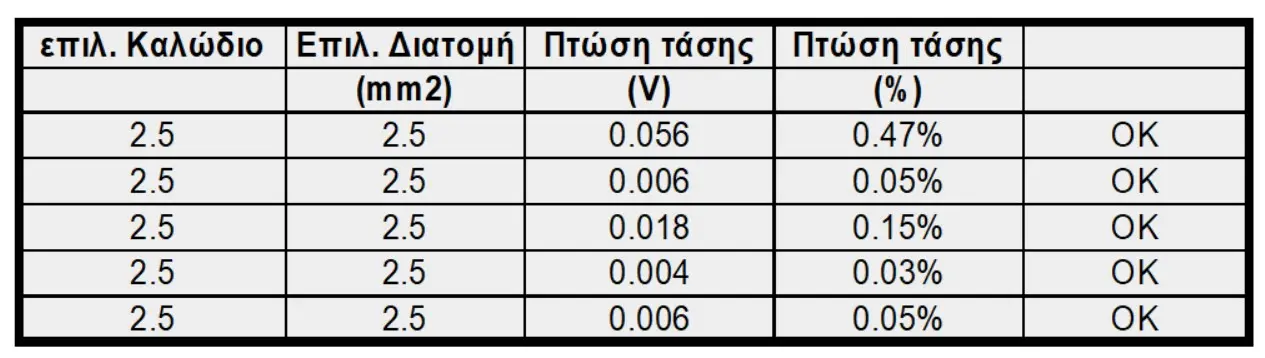
According to the calculation all the cables can be 2.5 mm2. However, for the two pumps I decided to use 4 mm2 cable and 6 mm2 for the main feed.

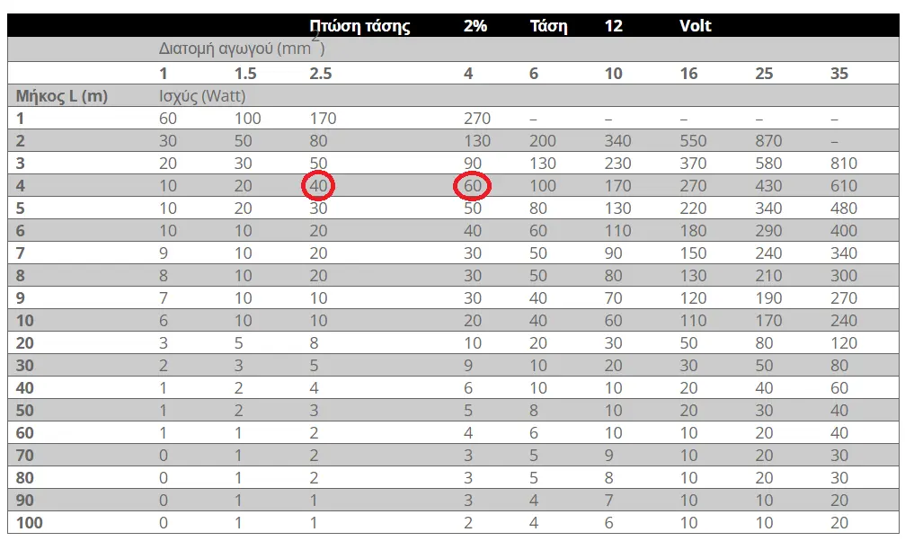
To check the figures I found the tables below, which confirm the current rating of the cables against their cross-section.

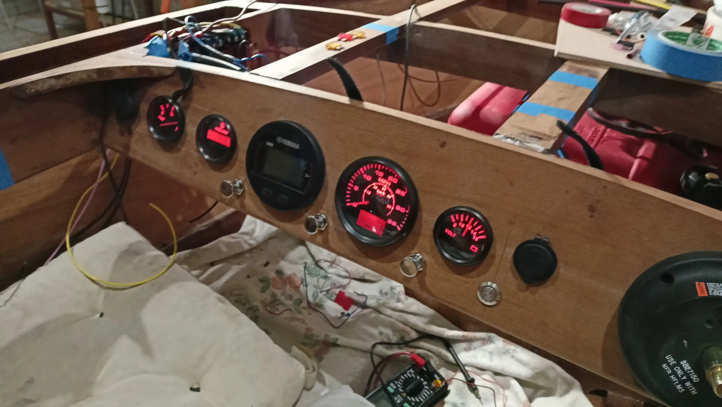
The first job for the installation is fitting the instruments into the dashboard. First the helm and the wheel went in, then the rest of the instruments. A first trial was made of where the control box should go but I have not settled on the position yet. The first photographs are below.

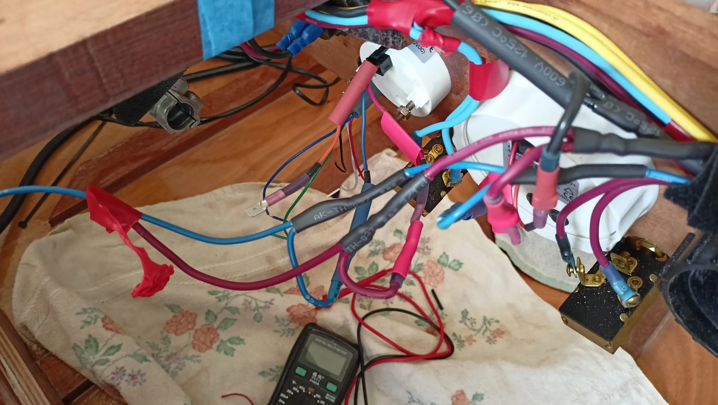
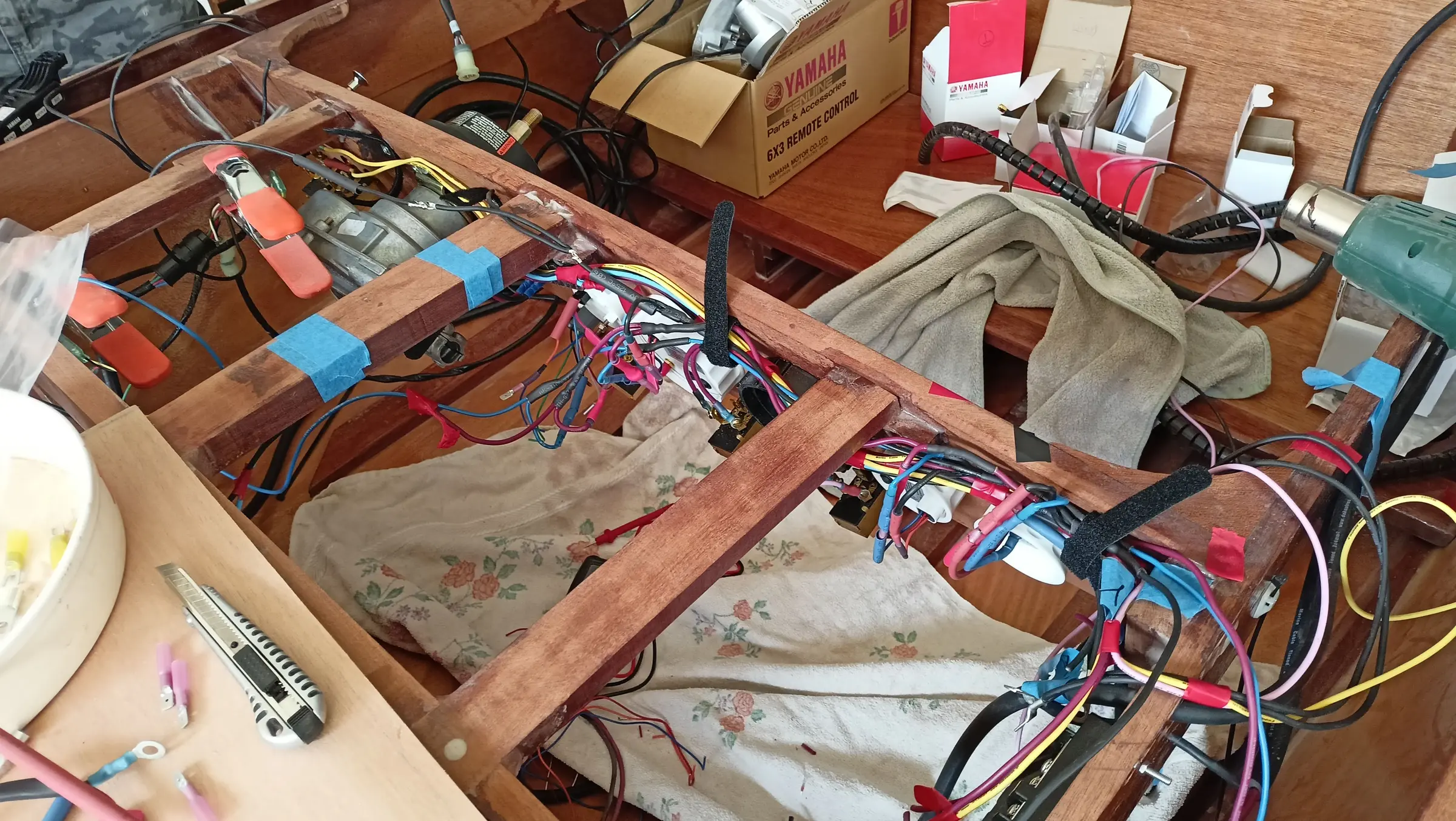
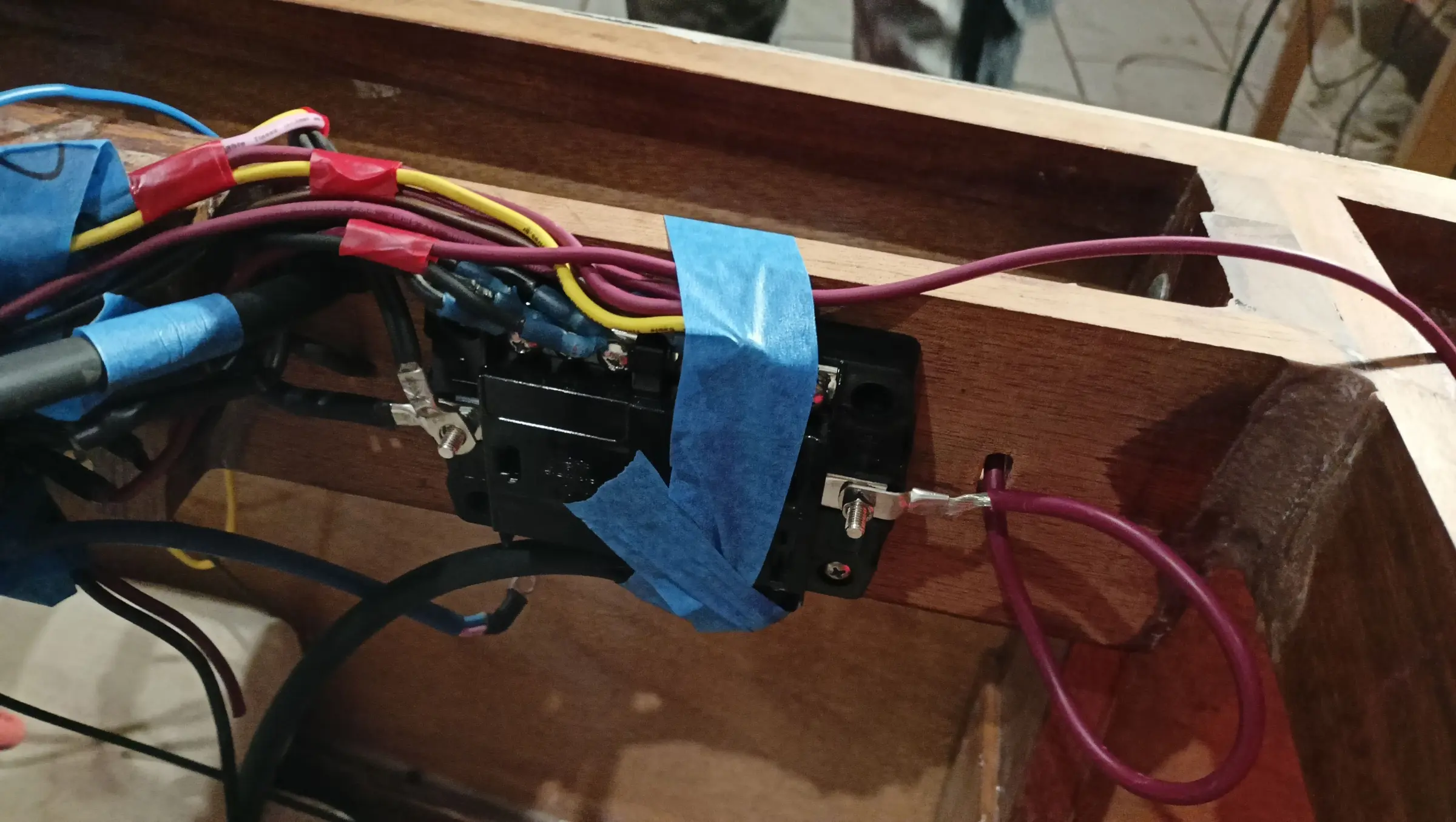
And a few more of the cabling going in.


Interior work No. 5

This section covers pretty much all the necessary work inside the boat that has to be done before the plywood goes on. The fuel tank box was given two coats of resin, and the area that will sit underneath it got epoxy primer and paint, apart from the areas to be glued.

So the tank can be held down onto the box, holes were drilled for the straps that will tie it down.

Finally, blocks were glued in for the base to sit on and they were all brought to the right height by gluing thin pieces onto the ones that were lowest.

Alongside that work, certain areas where no further work will be done are being painted with the epoxy primer.

I decided to strengthen the transom even more than the plans allow for. So I cut two more knees, which were glued in to the left and right of the central keel knee.

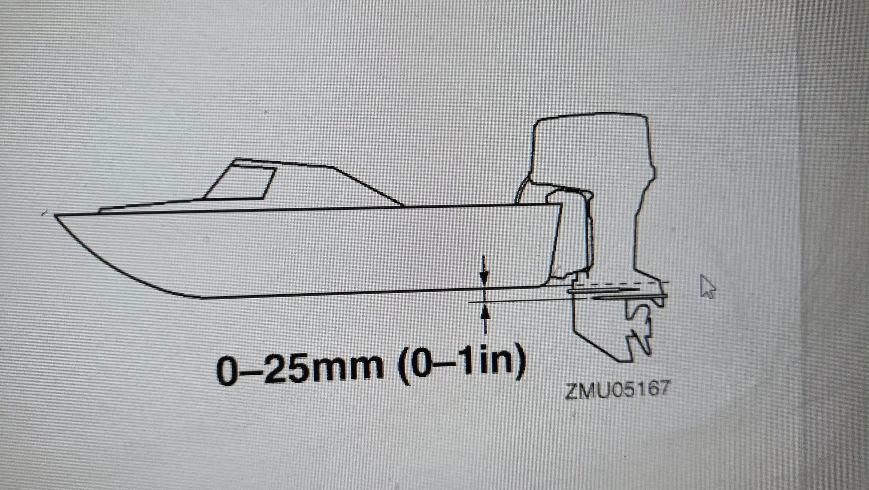
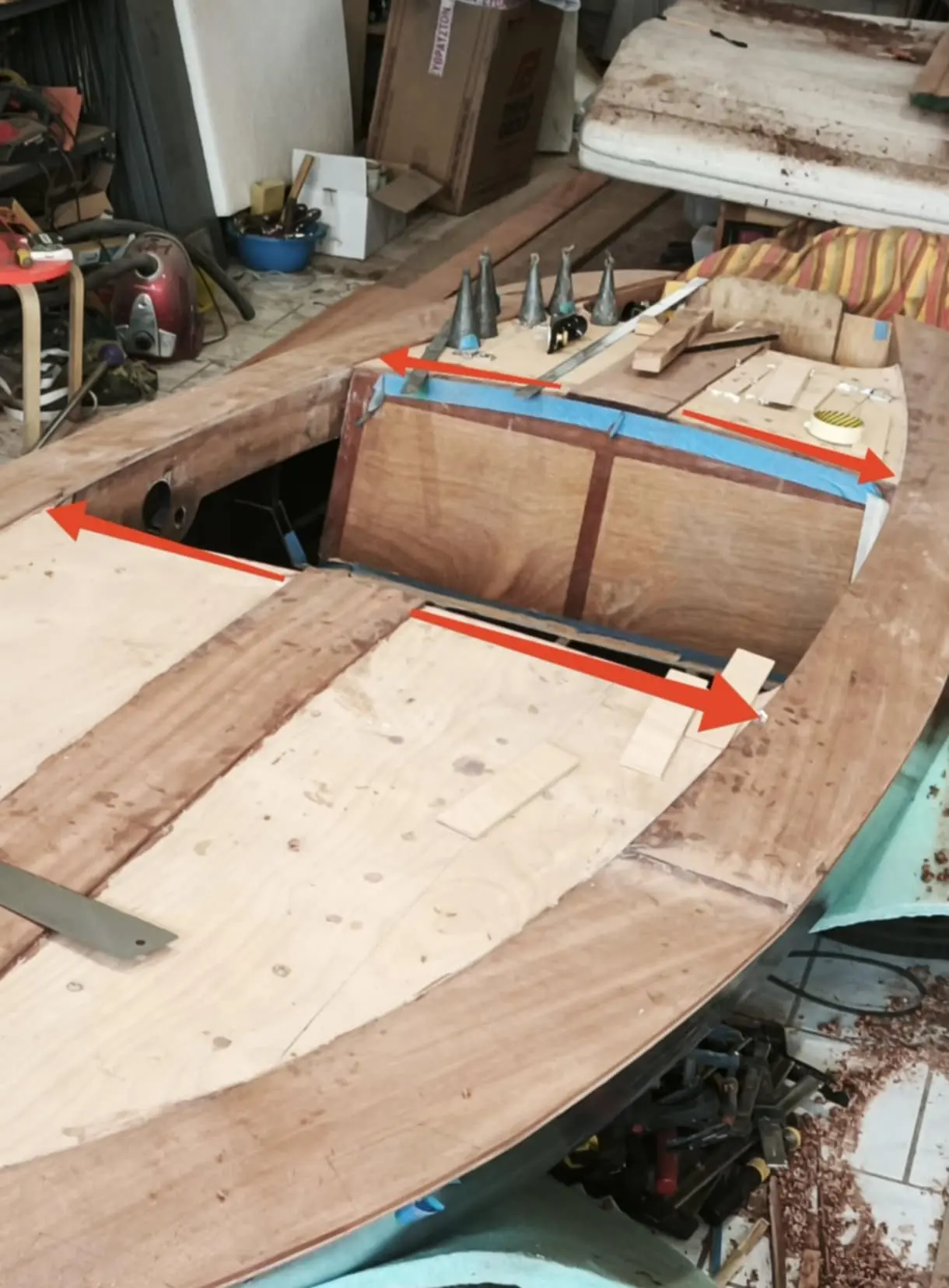
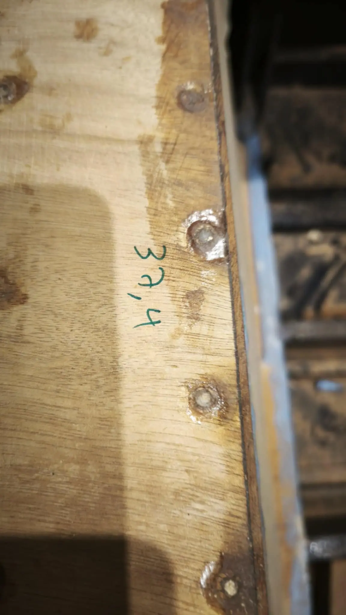
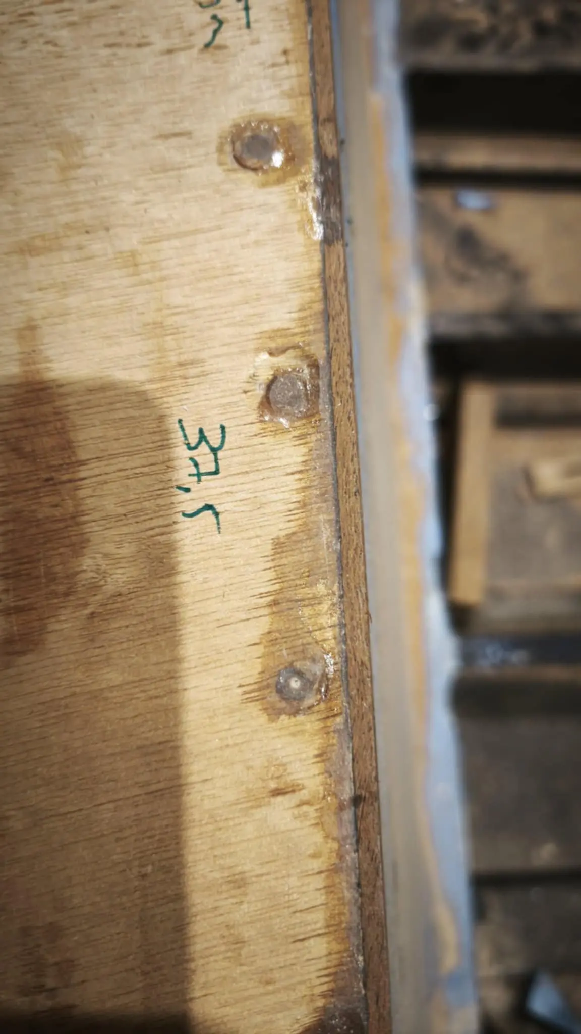
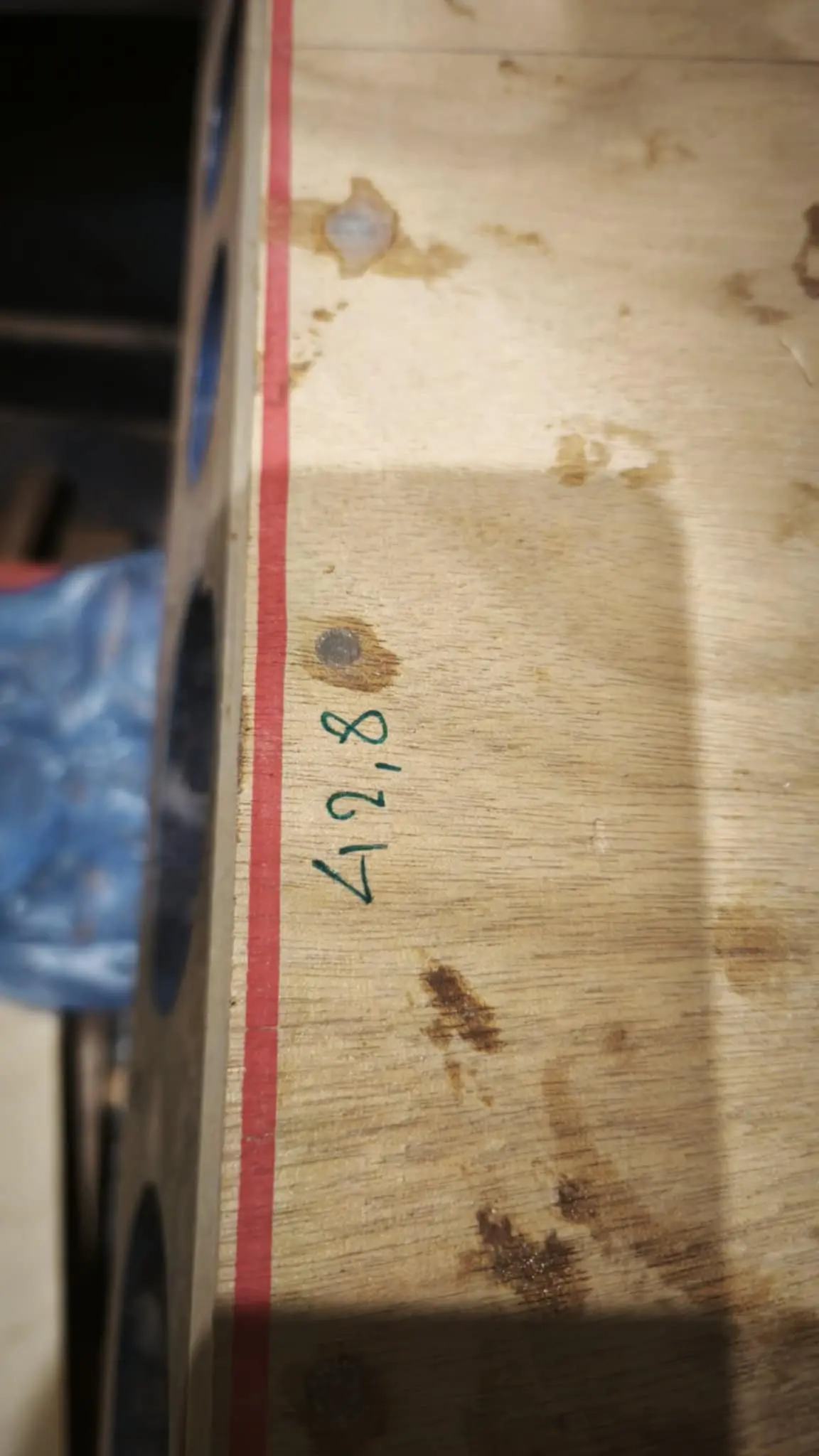
One problem with the plans is that the transom height is 37.7 cm. Modern engines want more. Specifically, the short shaft Yamaha I have bought is 42.4 cm to the anti-ventilation plate. Yamaha recommend the plate should be level with the hull, up to 2.5 cm below it.

So the transom will have to be raised by between 22 and 47 mm. I decided to raise it 30 mm, because the outboard clamps grip 30 mm down from the top edge of the transom. To do that, 7 mm plywood was glued on the inside and 30 mm sipo on the top edge of the transom.

The last piece that had not been glued in aft was also glued.

At the same time the fuel tank box is being prepared for gluing. First and second coats of epoxy primer went on, then the paint.

The next job is building the aft end of the boat.

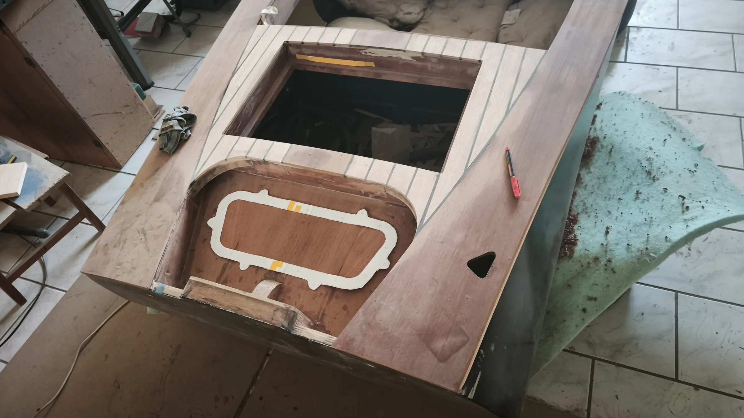
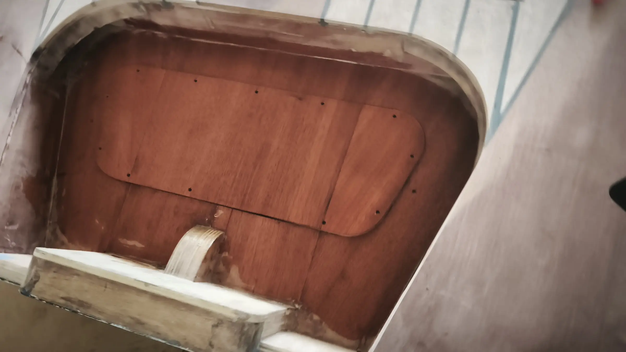
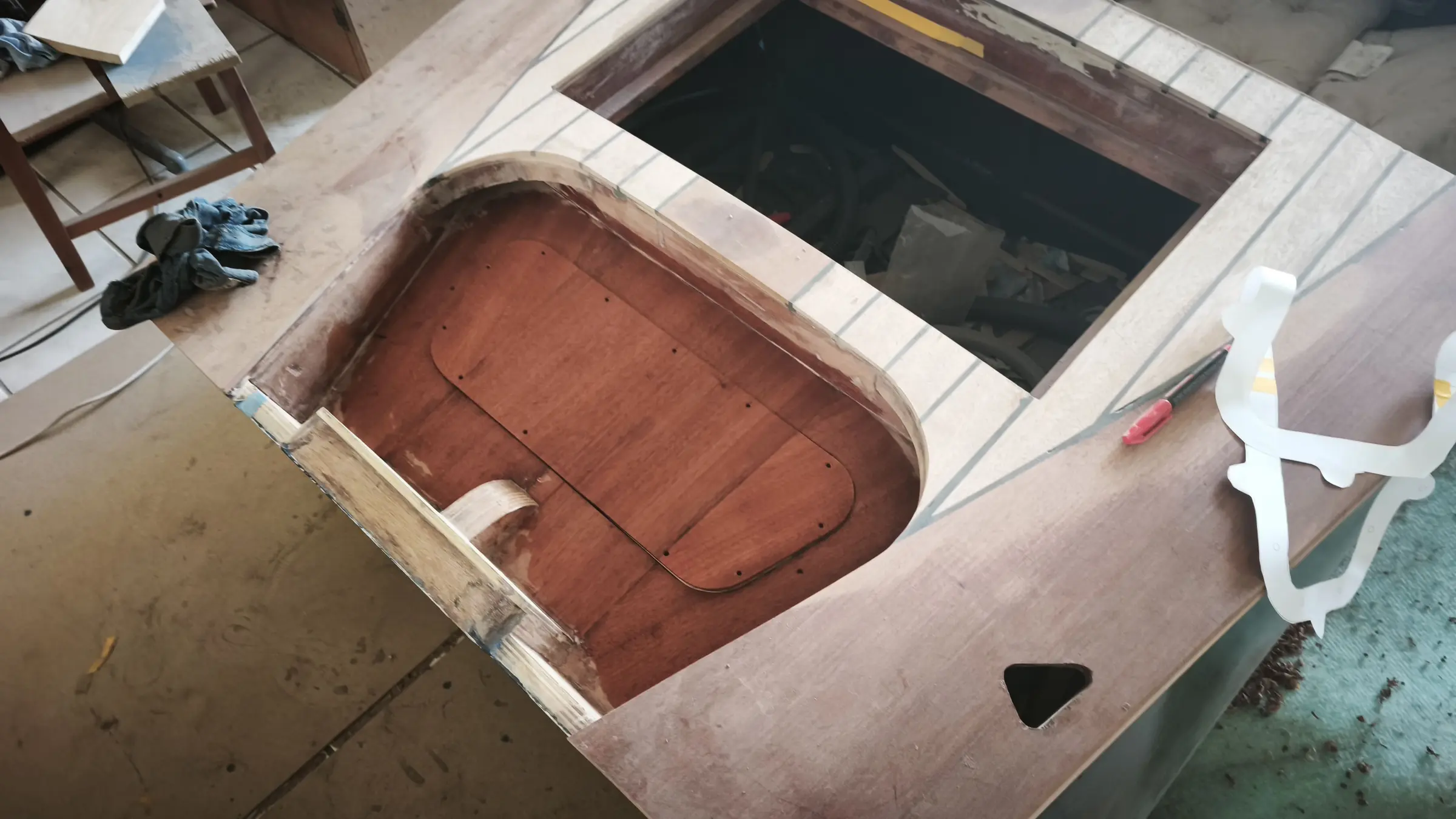
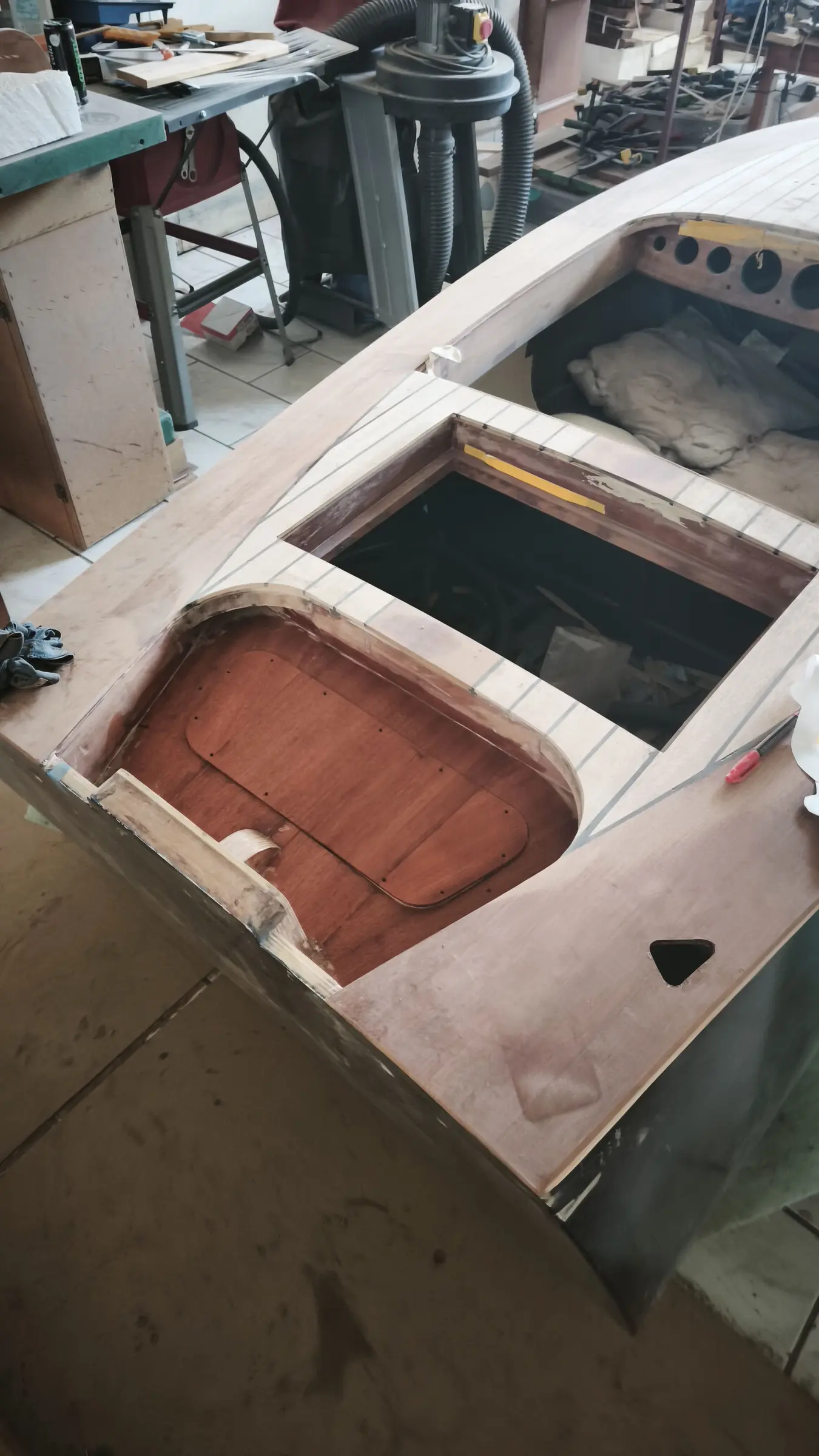
I decided to close it in and leave an opening so I have access to the pumps. It will be closed with plywood and, on top, timber to match what is going on the rest of the boat.

The bearers the plywood will sit on were cut.

The next job will be cutting and fitting the plywood.

To do that I had to take a pattern of the opening. Using offcuts from other jobs screwed together, I made the pattern and transferred it to plywood. The process is below.

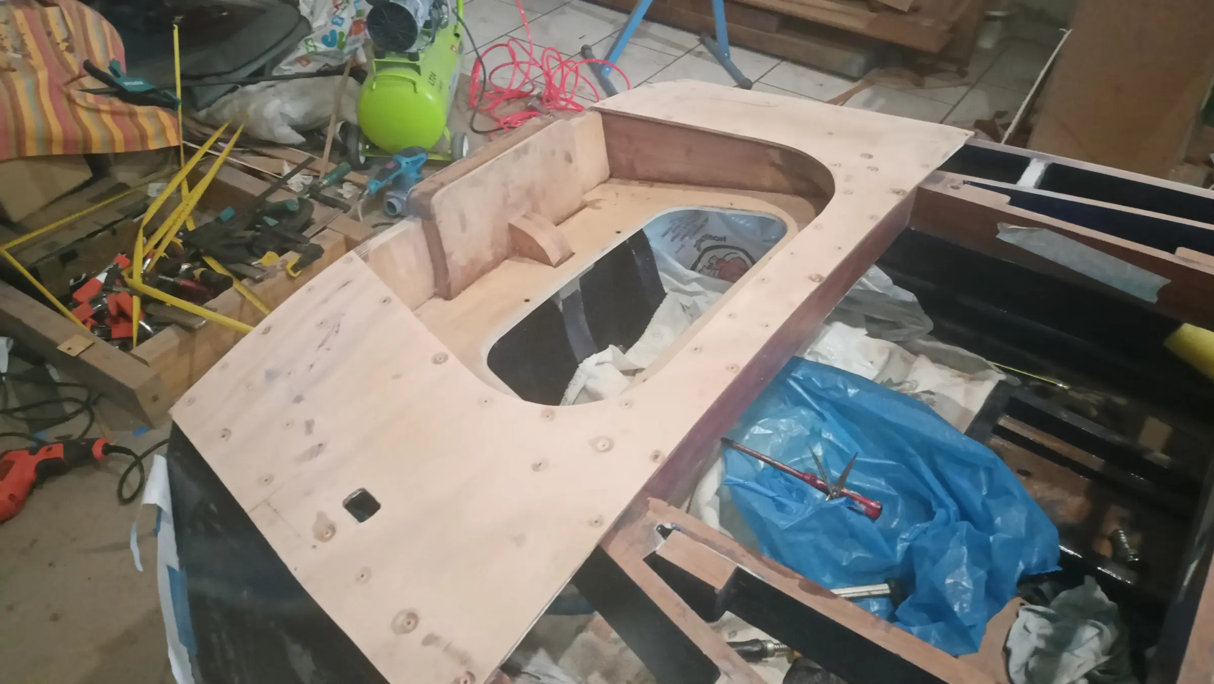
Once the lid fitted, I glued the pieces it sits on, apart from one at the side, because a hole will be cut at that point for the engine cables to pass through. So I want to work out the size of the hole and its exact position first and then glue the piece, so I can get the router in.

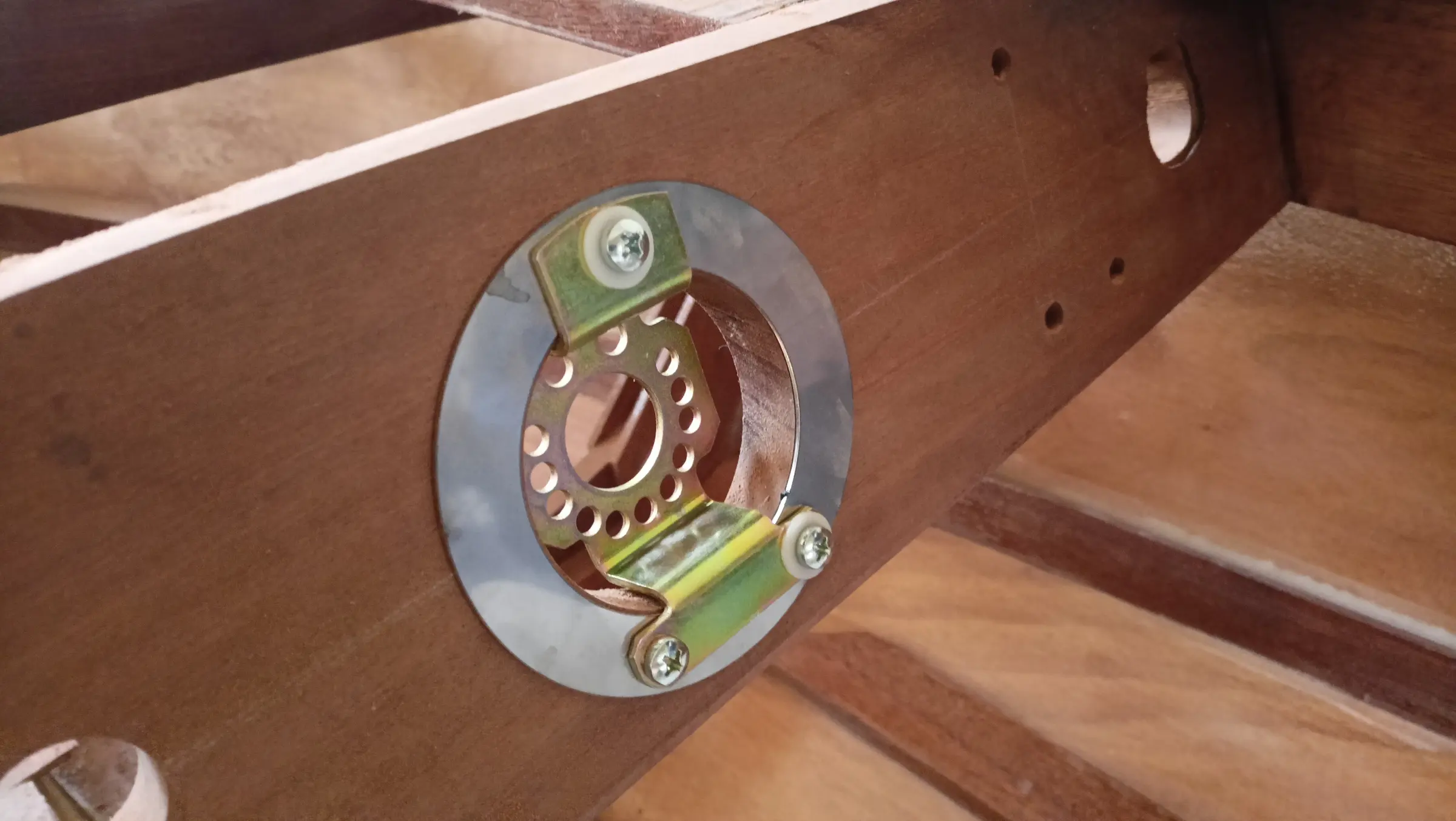
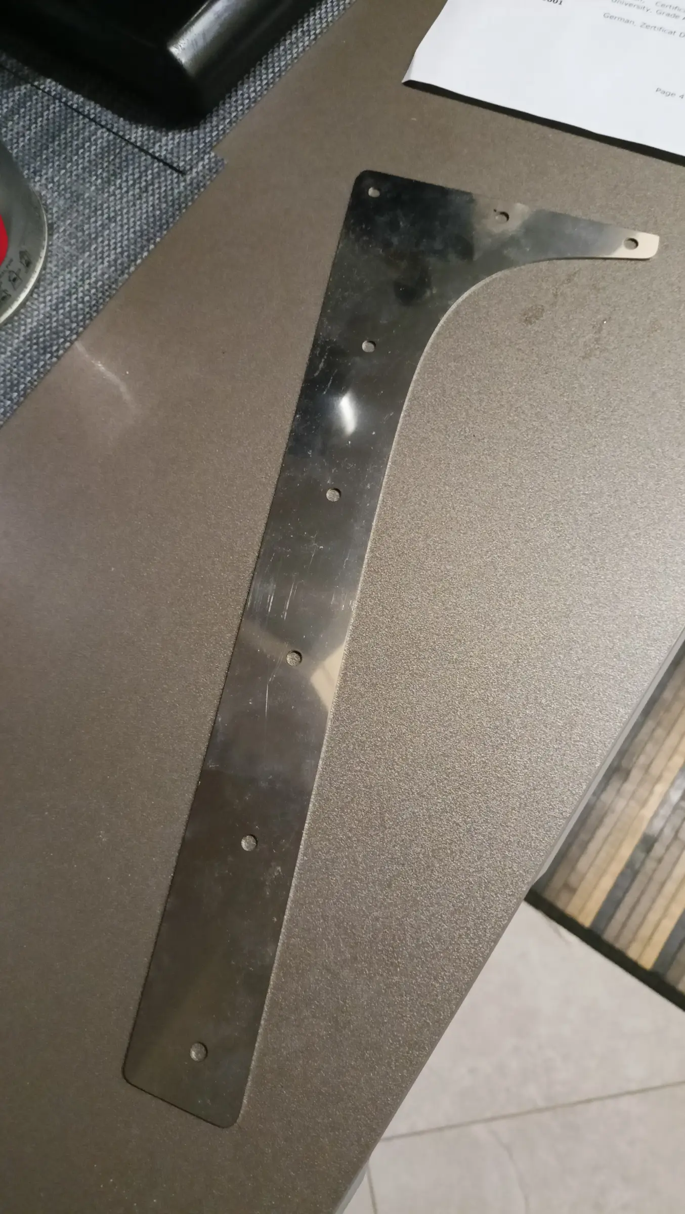
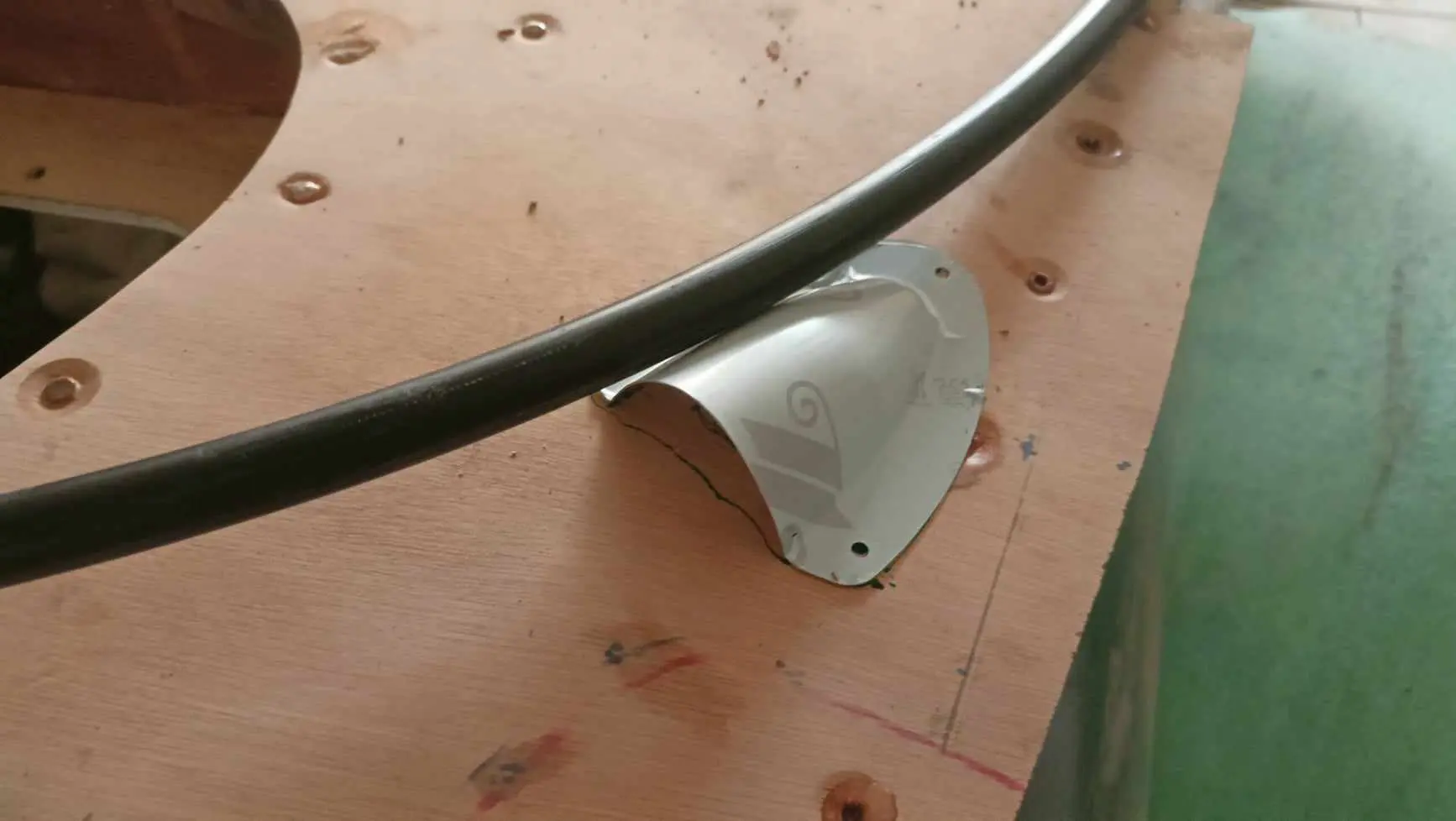
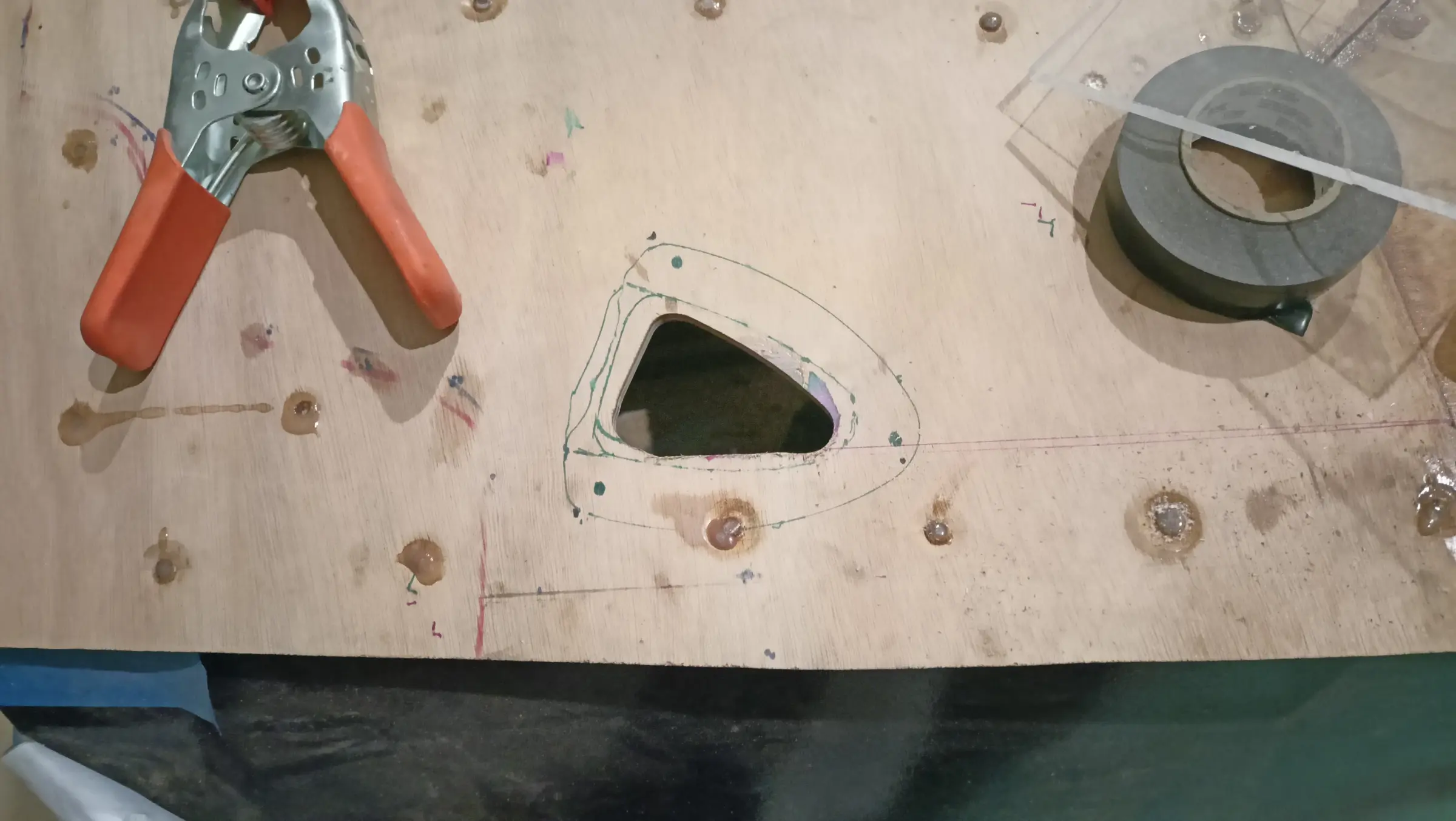
For the hole I drew the design below on the computer. The hole will be laser cut and the stainless steel in the photograph will go round the edge. I made different sizes of hole, I have not settled on the best size yet.

Some details I made are the following reinforcements.

Before gluing them I sanded off the epoxy primer (Hempel light primer) that I have applied over the whole interior of the boat.

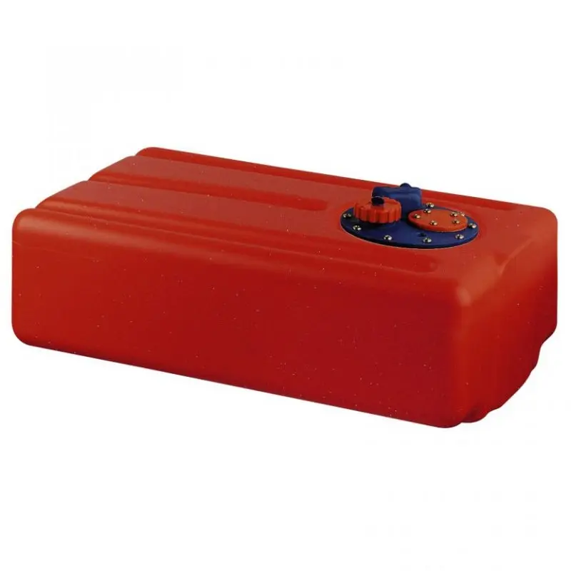
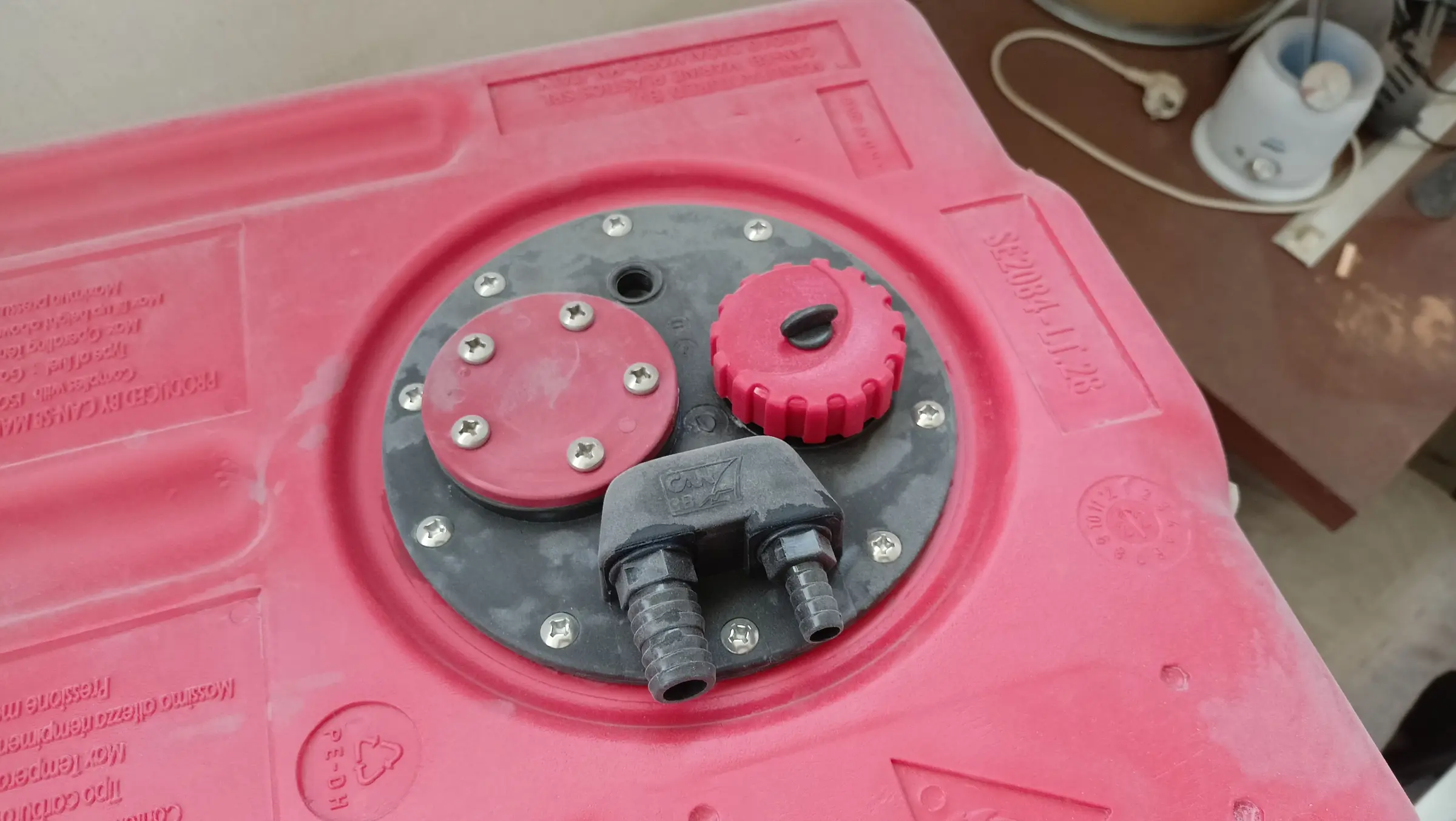
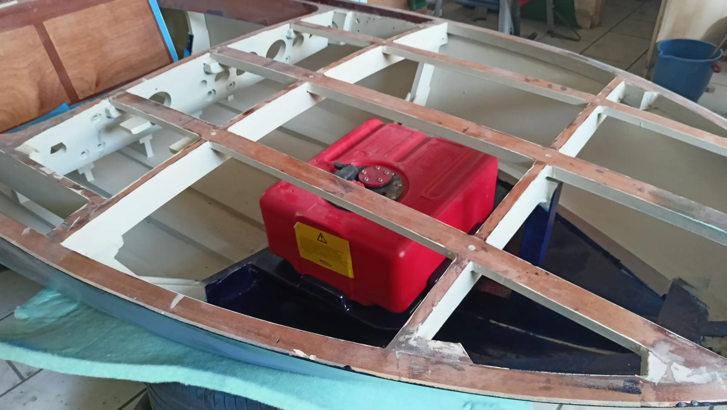
After a good deal of thought and searching I decided to replace the Yamaha tank with another one. The main problem is that the Yamaha tank had no option for venting. There was no built-in fitting for the pipe and I would have had to make a tee off the feed line or drill a hole in the tank. Not a serious problem, of course, but since a suitable tank turned up I decided to swap it. The new tank is 28 litres and is the one below.

Its external dimensions are different from the previous one, so I had to make a different base for it to sit on. The new base is below. It has had epoxy primer, it will be painted underneath, and it is ready to be glued in.

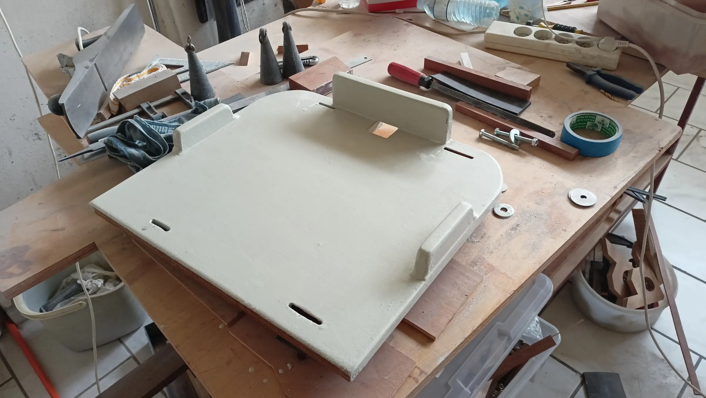
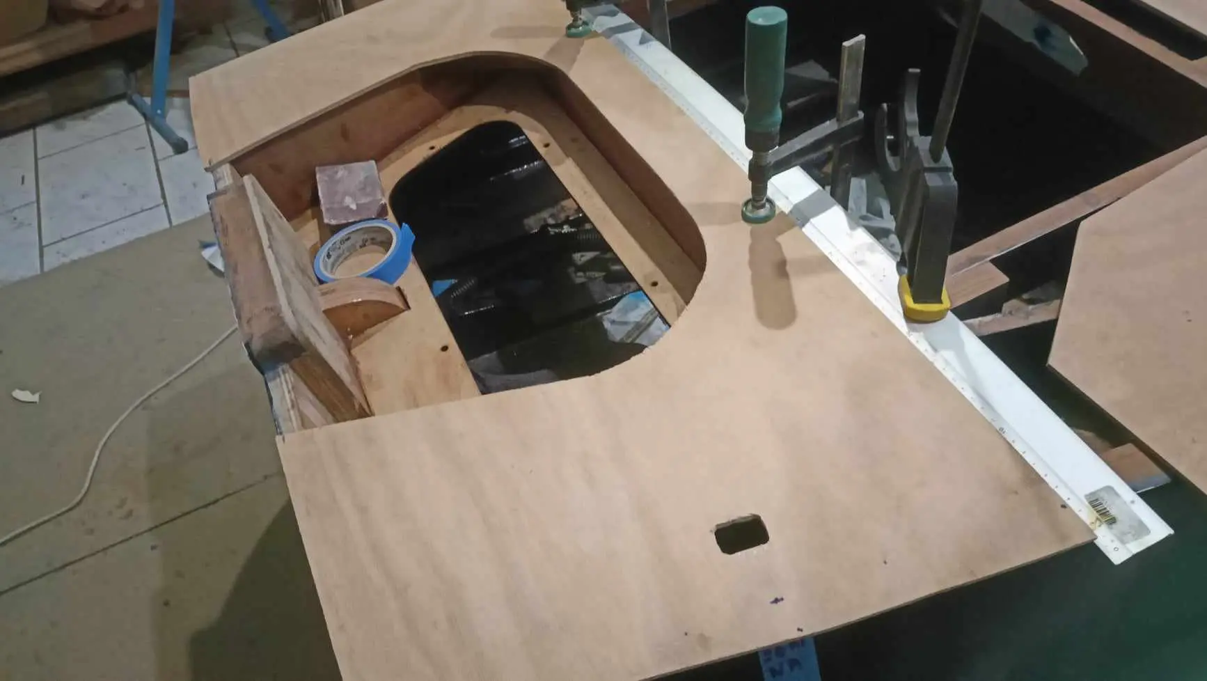
Finally, I made the locker lid. With it clamped up as it was, I got the curves exactly right. I cut it into the two halves that will open (left and right) and glued the plywood onto its top face.


Painting, second attempt

The first attempt at painting the boat did not go well. I think the problem was that the hull surface was not right. There were quite a few irregularities in the surface and the texture had gone like orange peel.

The surface was sanded and the paint came off, working up to 320 grit. It was filled again to get it as smooth as possible.

Then four coats of primer went on (Hempel light primer).

This was where I went wrong the first time. After the epoxy primer it needed a good deal more sanding.

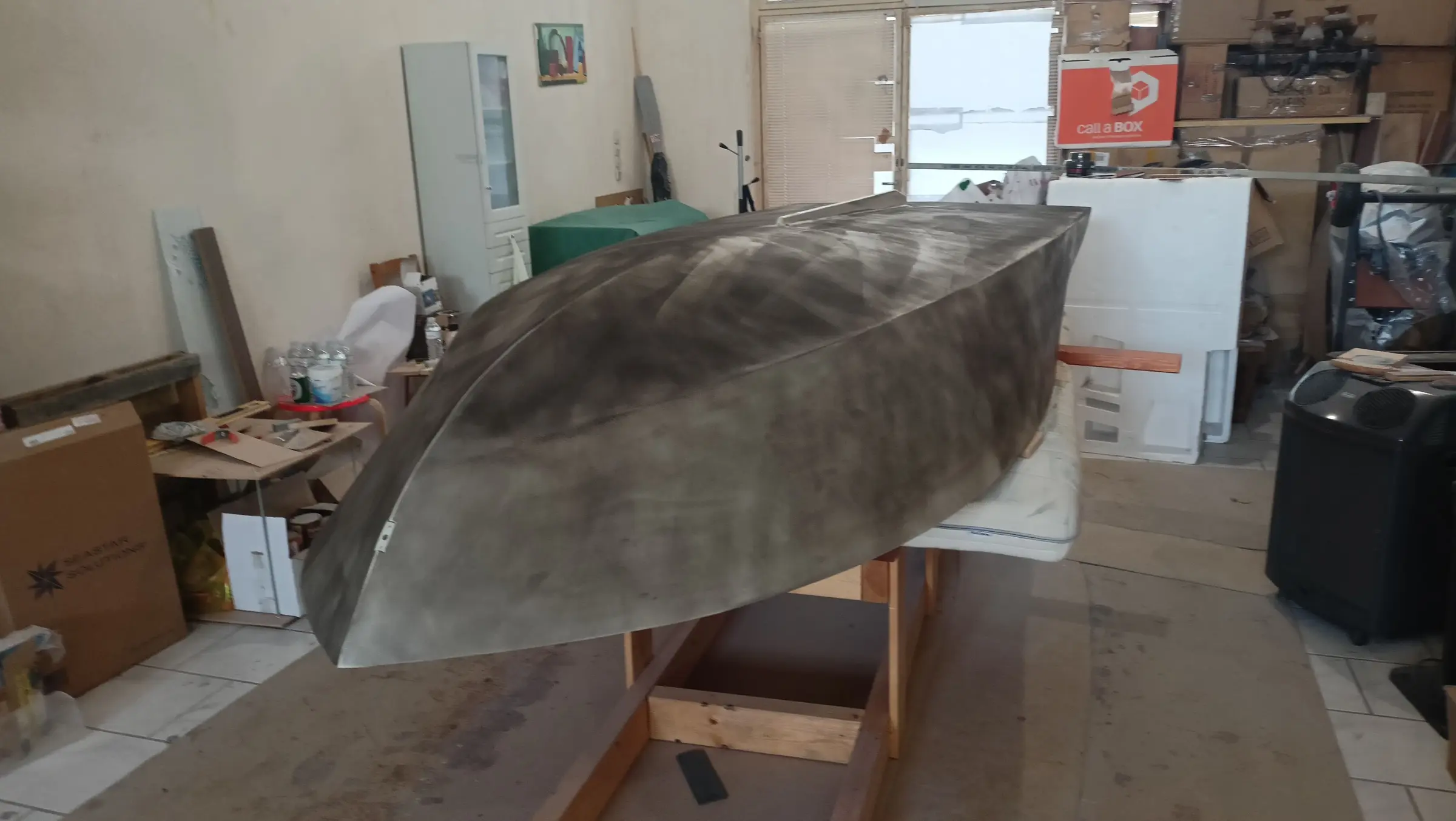
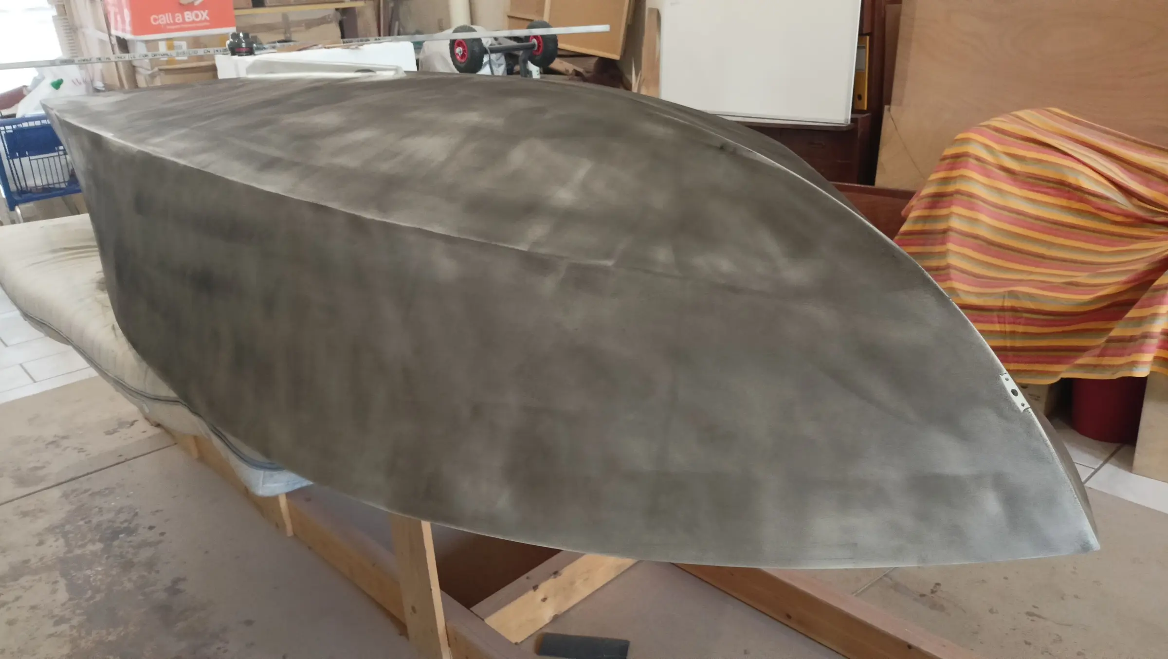
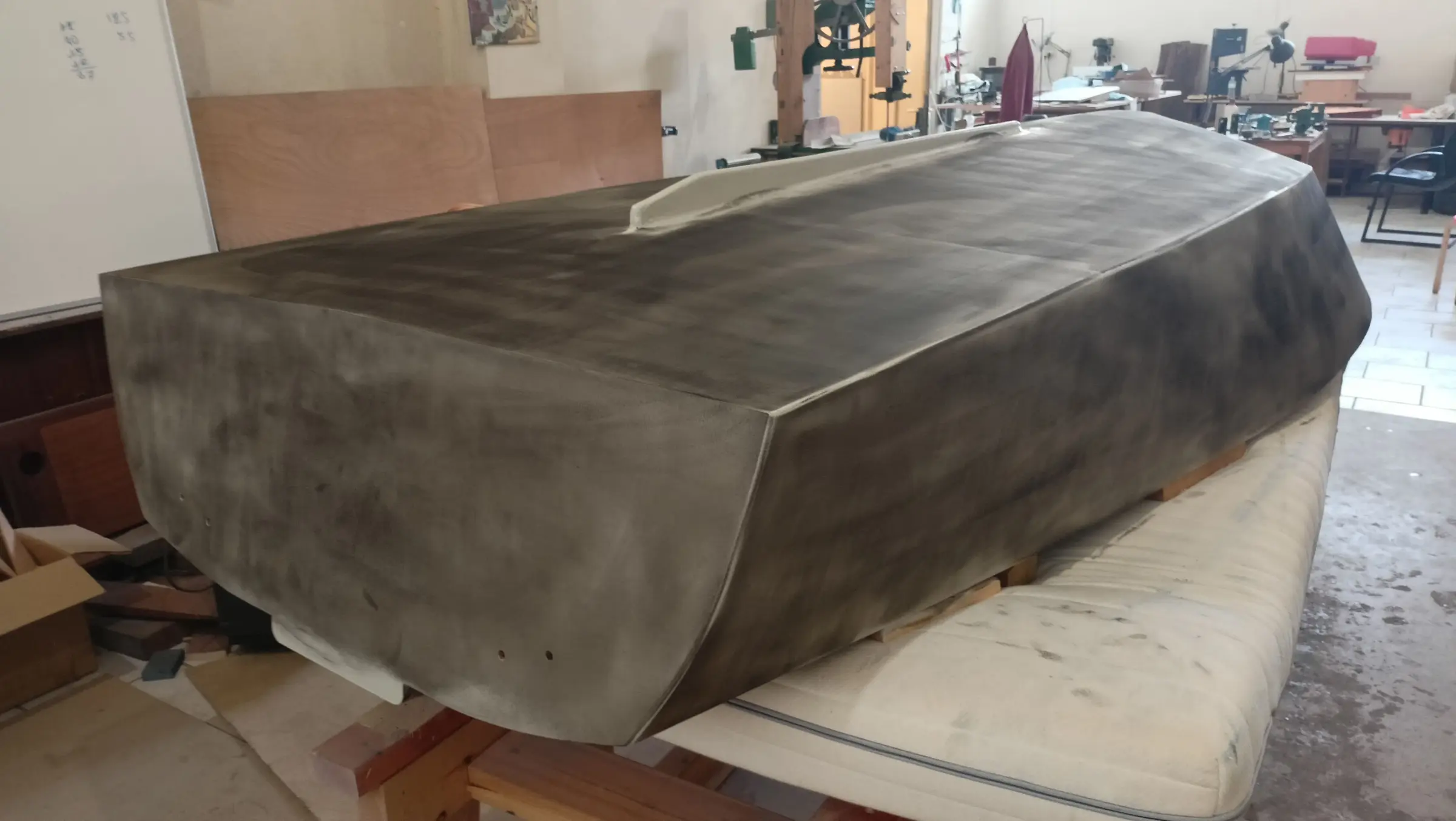
To be sure the surface would be completely smooth before painting, I used a black guide coat powder, which you spread over the hull and, as you sand, it shows you the irregularities. The surface is perfect when all the powder has gone. The product is below.

Some photographs of the process.

I started with 240 and worked up to 400 dry, then, on the advice of a friend who paints cars, used 800 grit wet.

I think the surface has come up very well for the paint to go on.

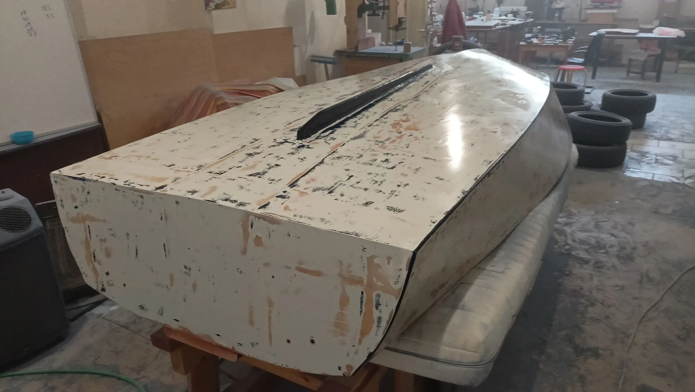
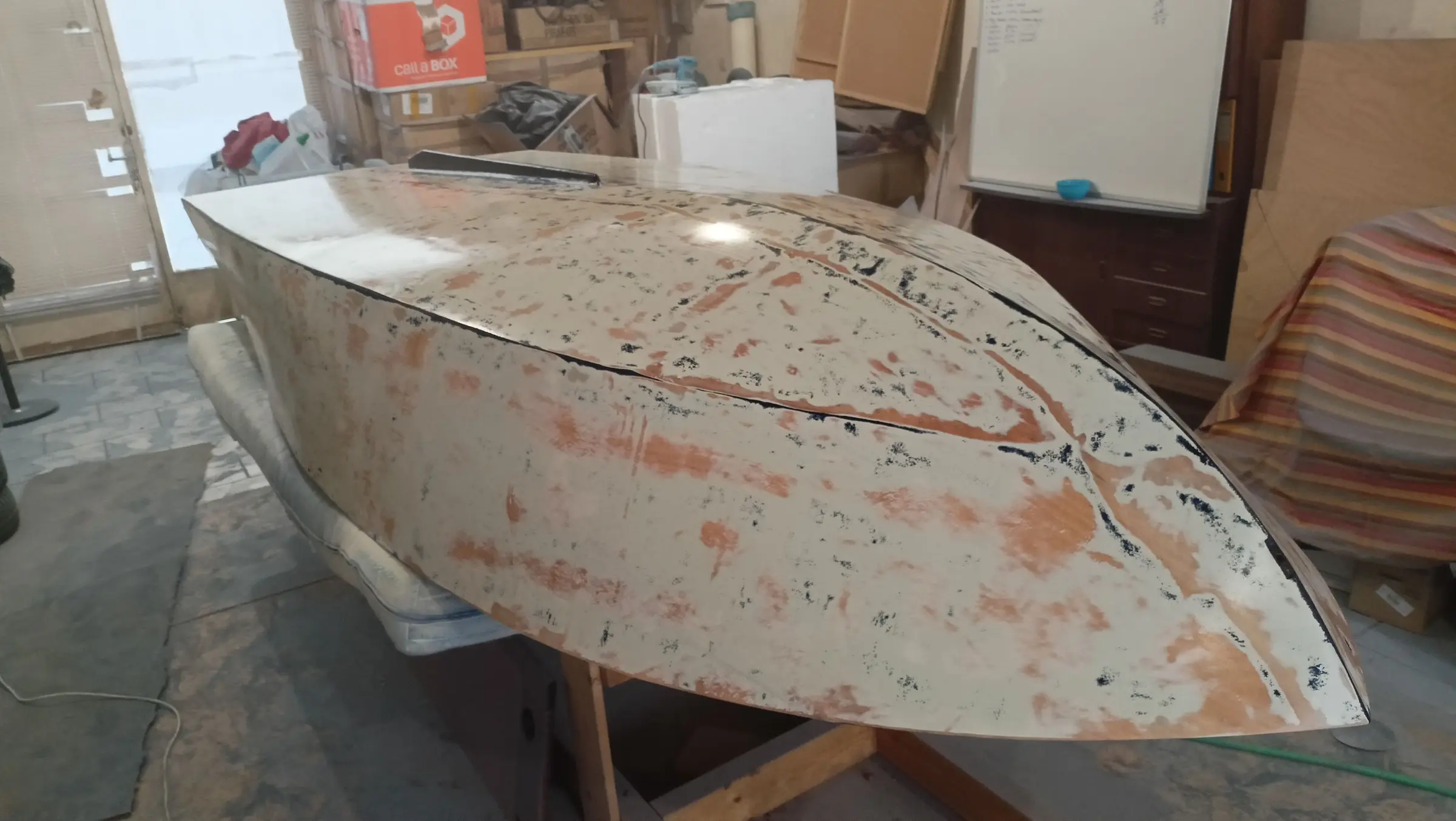
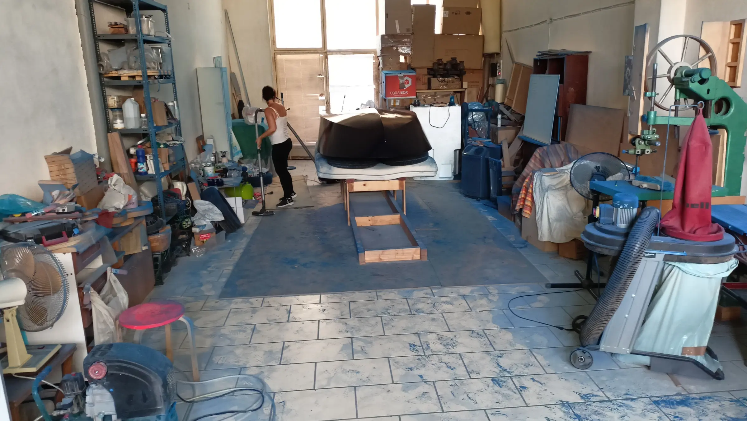
The paint went on in three coats, sanding between them with 320 up to 500 grit. The result is better than the first time but there are certainly imperfections. I will come back to it once the boat is finished and spray it. The workshop filled with dust from all the sanding. It probably needed one more coat.


Interior work No. 6

This article covers what are probably the last of the joinery jobs before the deck is closed in.

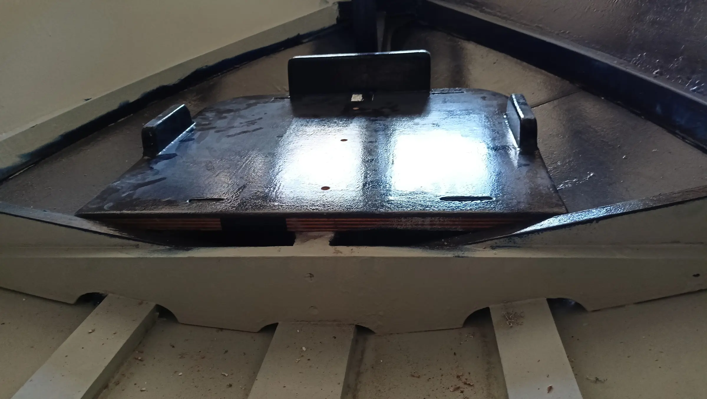
First I started work on the battery box. The box will be installed on the bottom of the boat on its fore-and-aft timbers. A frame was made that it drops into.

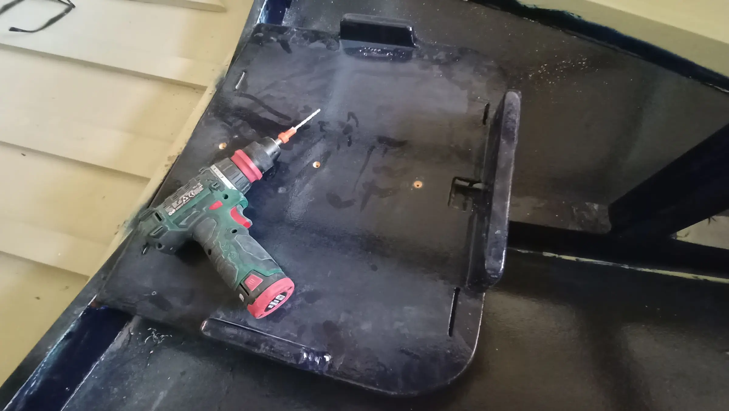
So that water has no contact with the timber at all, I decided every screw would sit in epoxy. For that reason oversize holes were drilled and filled with epoxy and microfibre. The outer faces of the base were also routed.

The epoxy primer was removed from the bottom of the boat where the base will be glued.

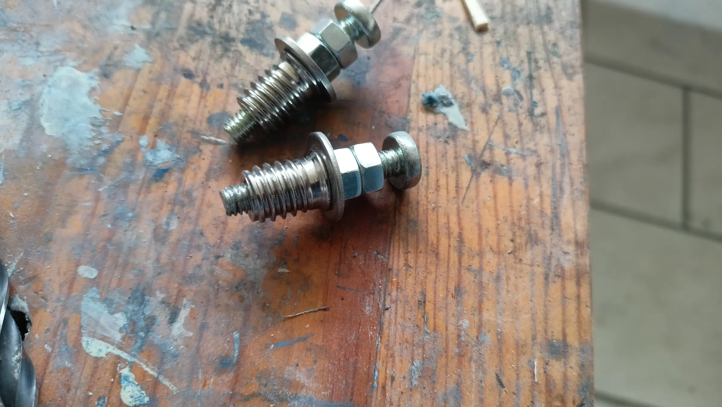
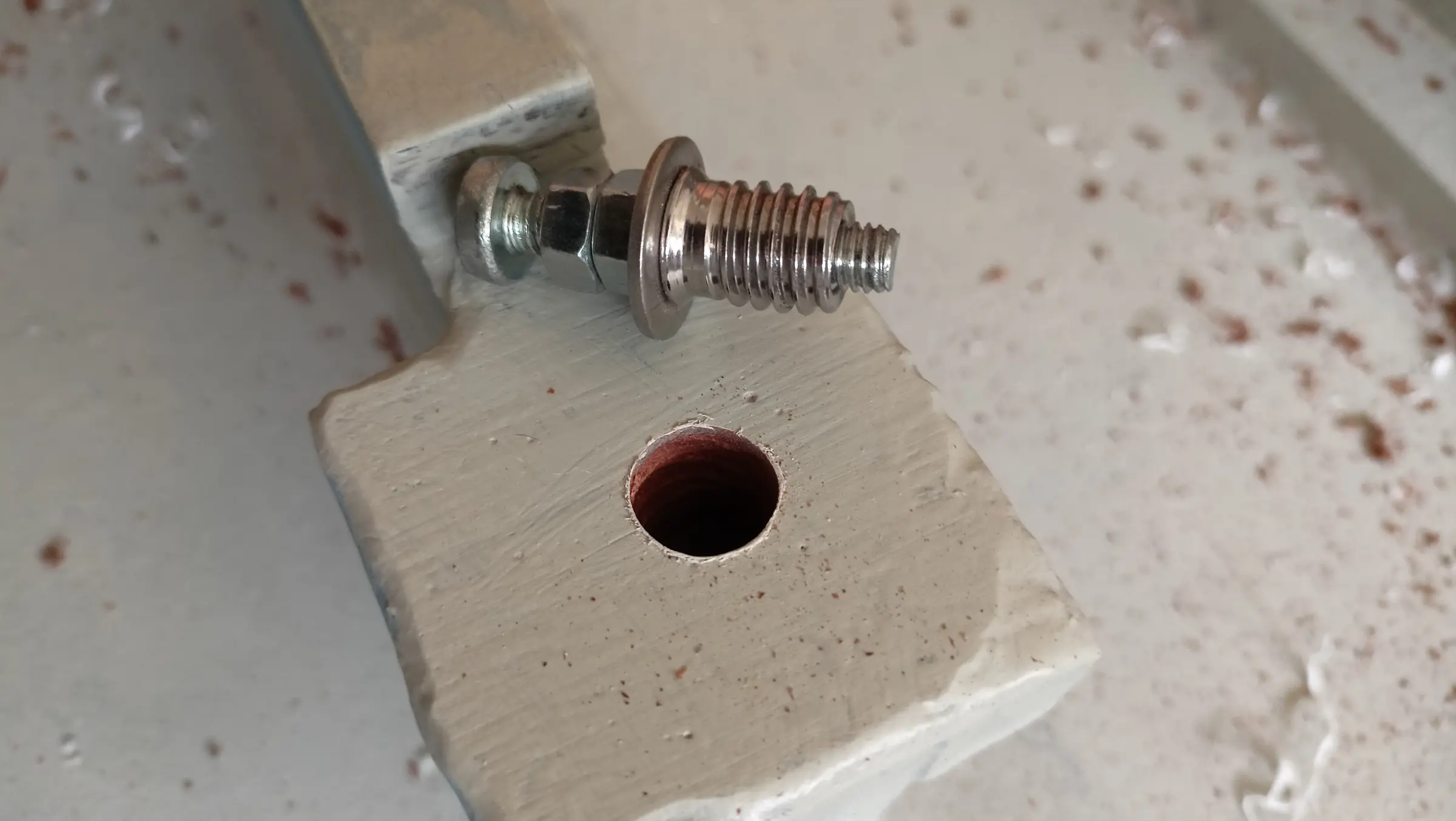
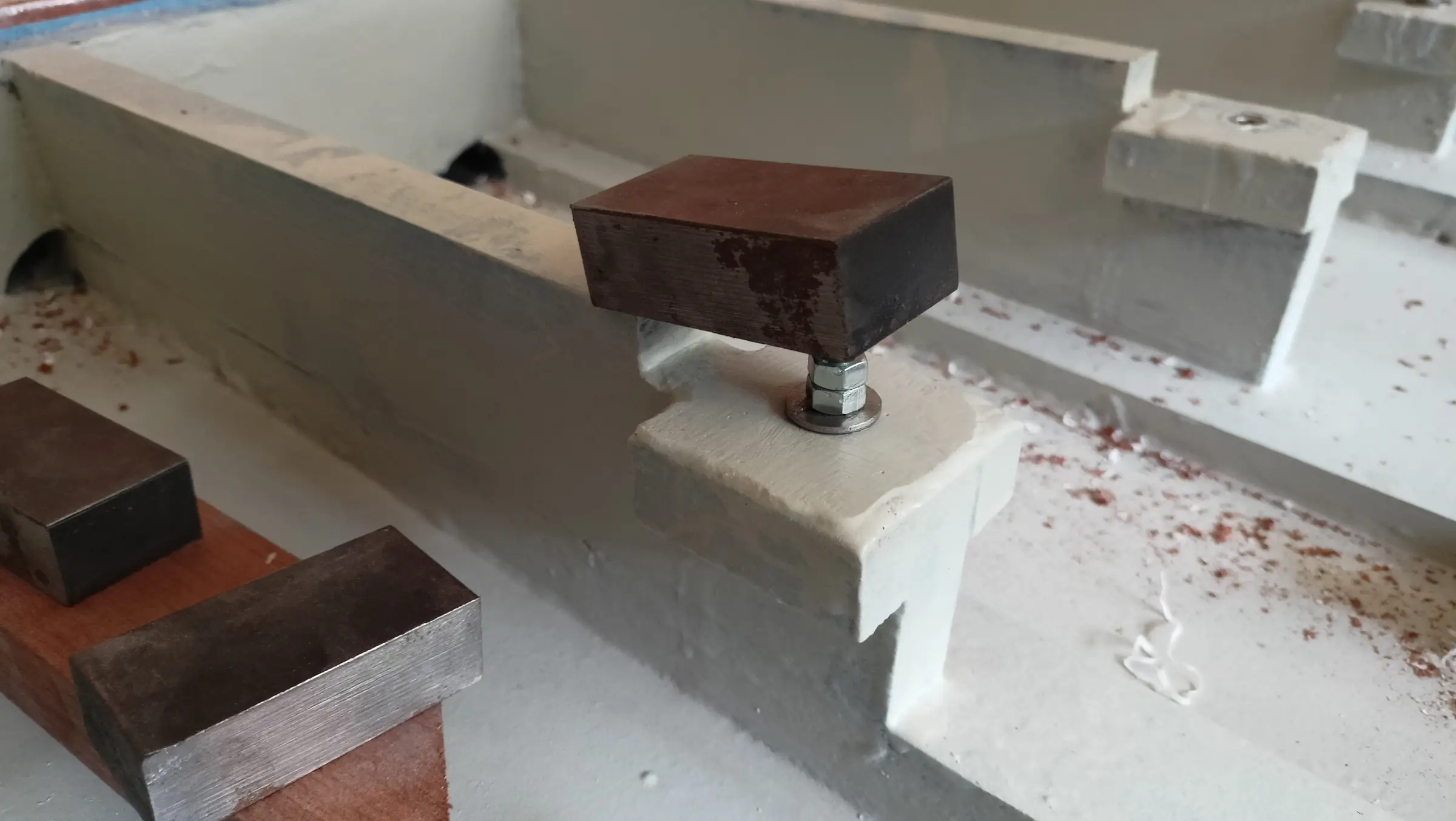
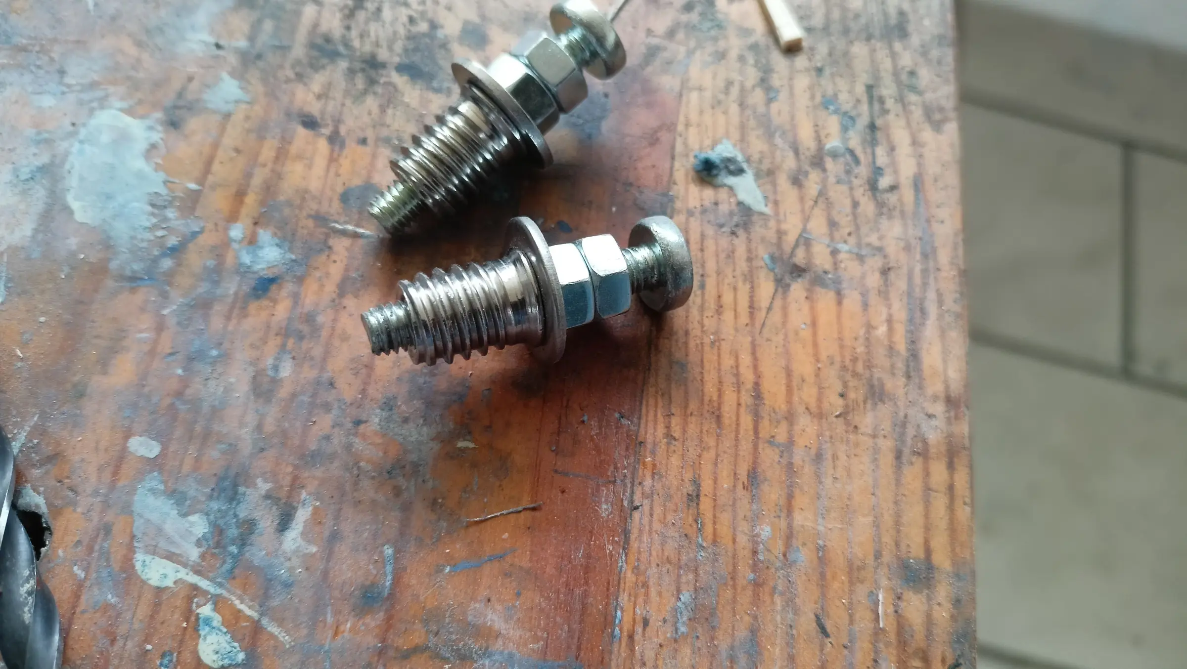
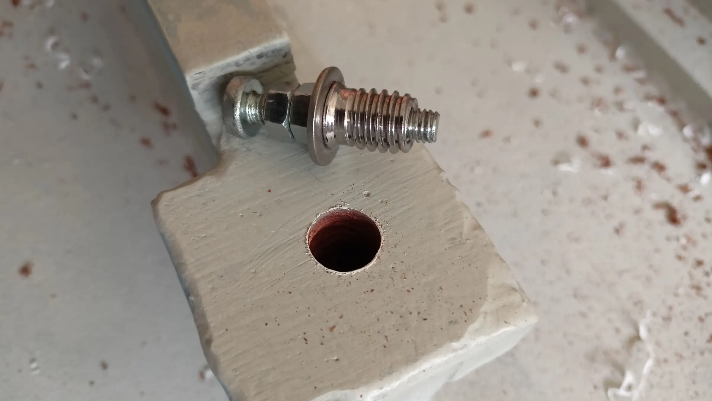
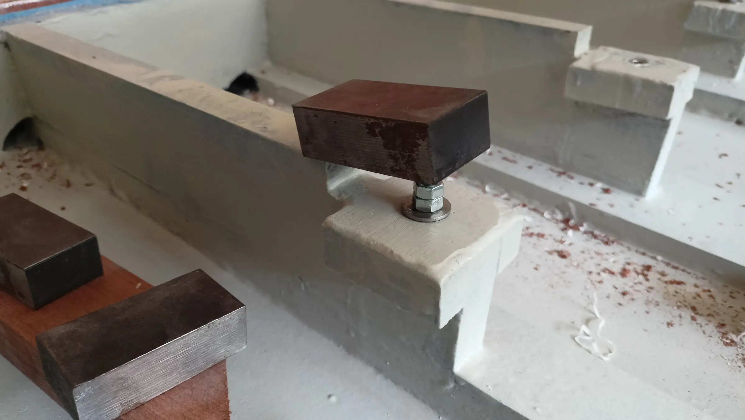
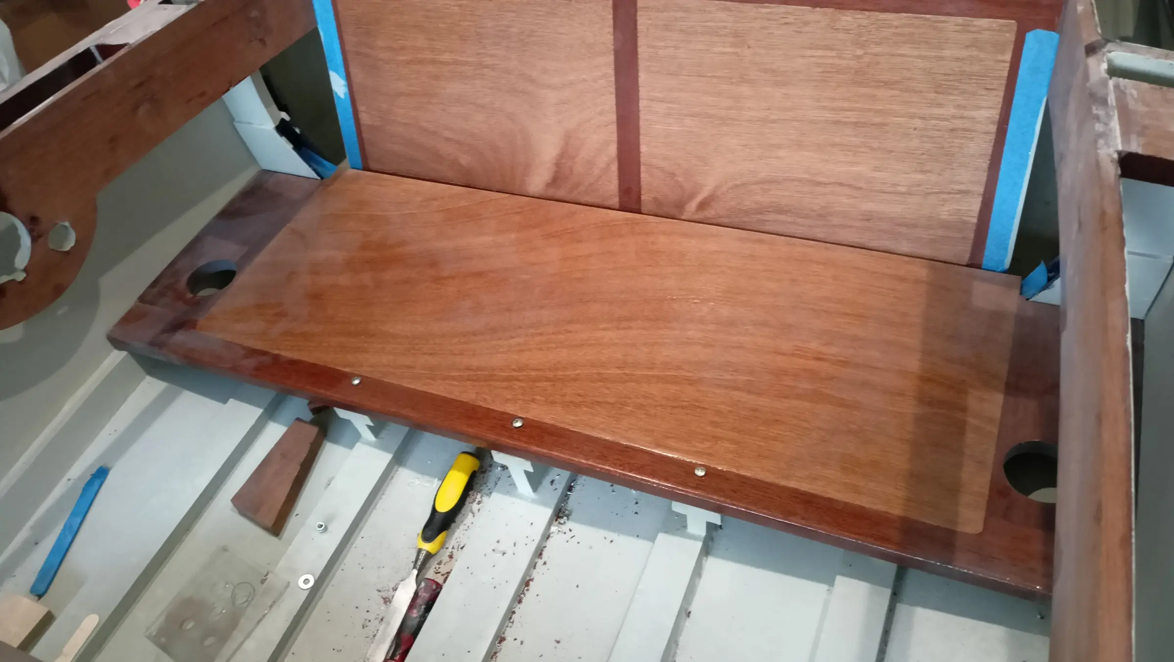
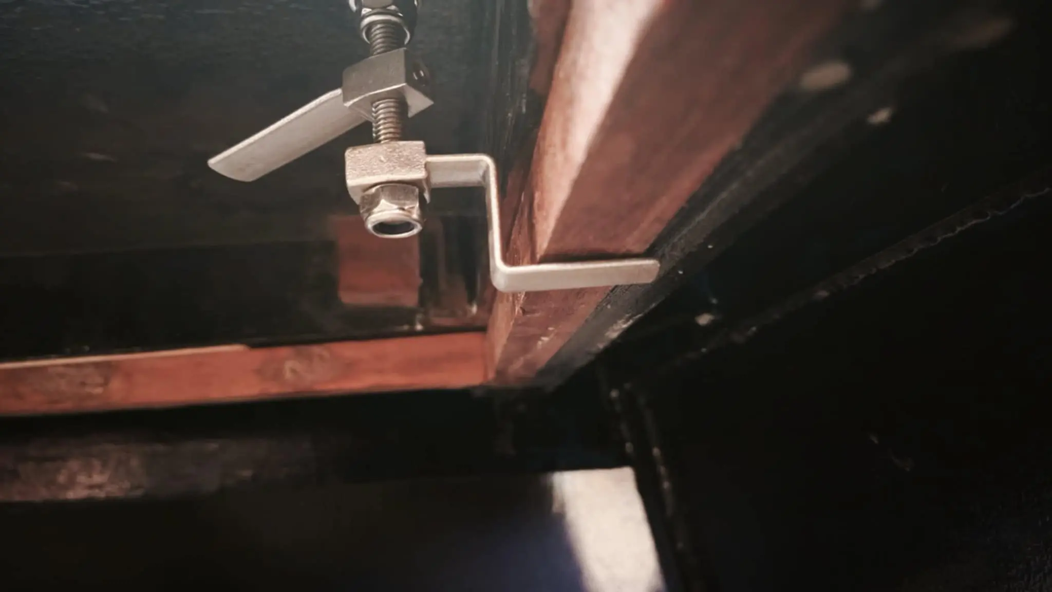
While the epoxy and the primer were drying I turned to fixing the seat to the boat's framework. Obviously I did not want to use wood screws, because I thought it would be good if the seat could come out, and wood screws would cause damage. So a hole was drilled, resin was put in it, and an insert for a bolt was fitted in the arrangement shown in the photograph. The washer holds the insert at the height I want, while the nuts set how far in the bolt goes. The whole assembly was sprayed with silicone spray so it would not stick to the resin. Five hours later the bolt, washer and nuts were removed and the insert was left in. The next day, once the resin had gone very hard, I took that out as well. That way a thread was formed for the insert, in case I ever want to take it out. Most likely it will never be needed, since it is stainless steel, but it is good to have the option.

Holes were also drilled for the pump outlets and for the stainless fittings. They were coated with epoxy and primer and will then get the polyurethane paint as well.

Before gluing the tank base and the battery box, the area I would have no access to after gluing had to be painted. That was the underside of the base and the hull, and the bottom and back of the box. Obviously the areas to be glued were not painted.

The battery box base was then glued in, in the way shown in the photographs.

The next job was gluing the tank base.

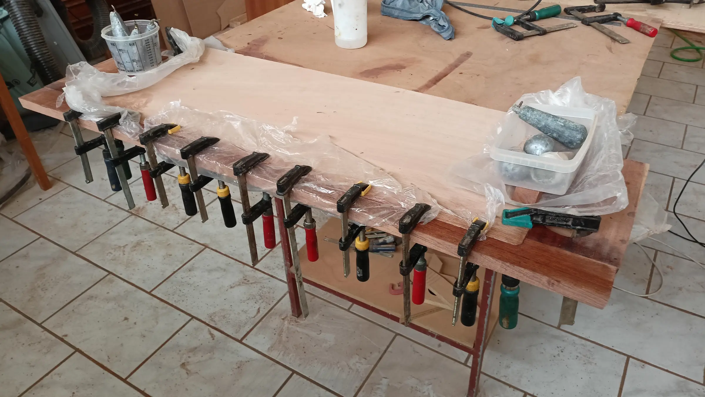
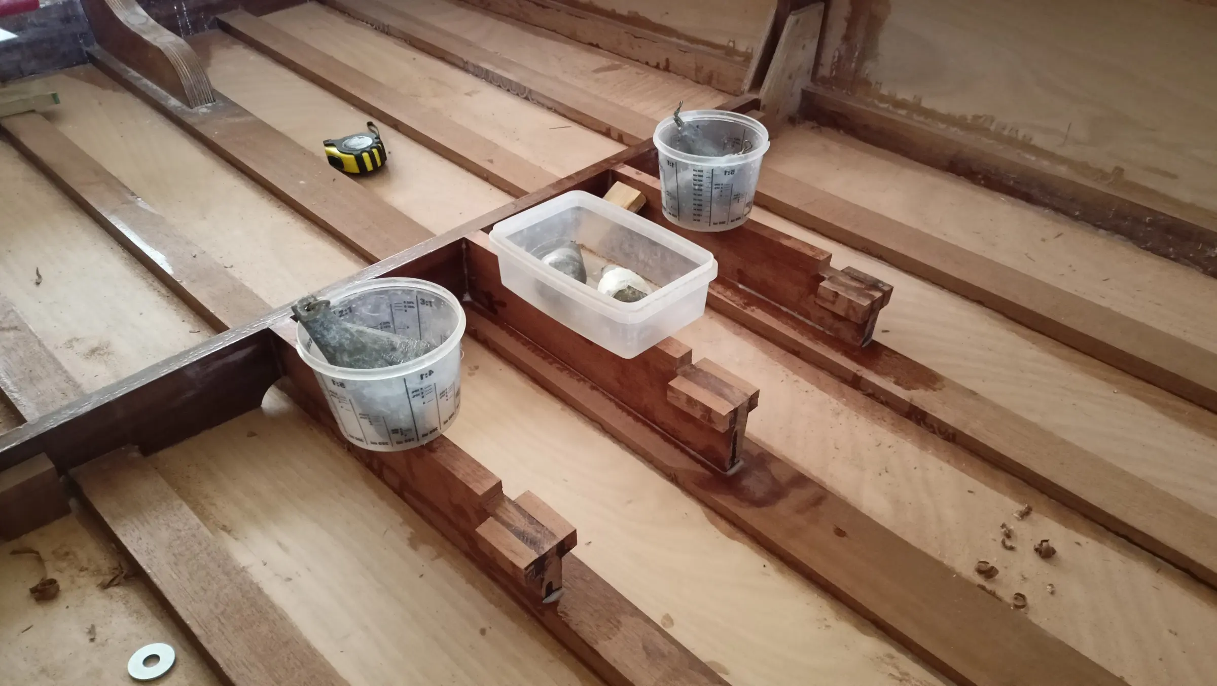
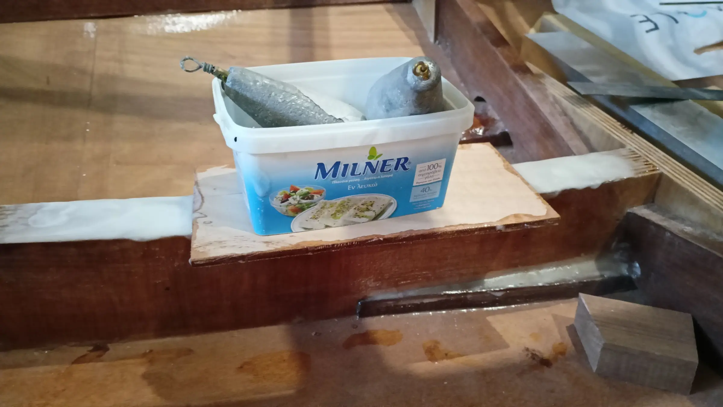
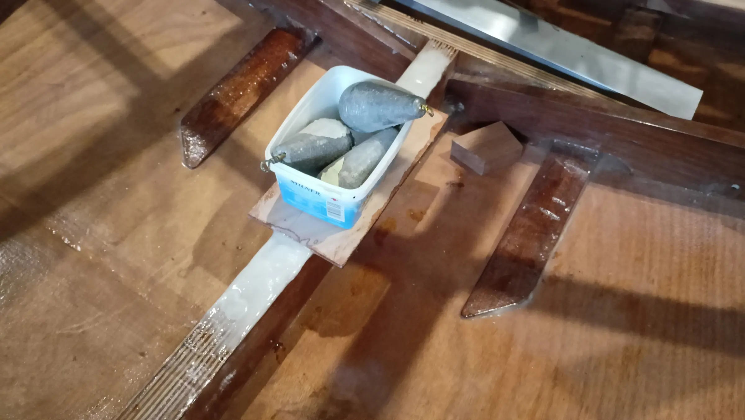
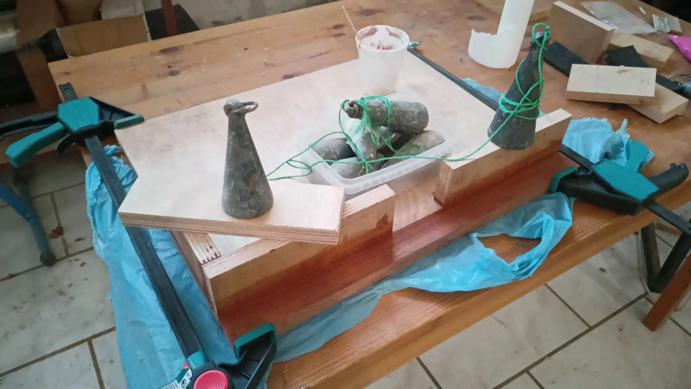
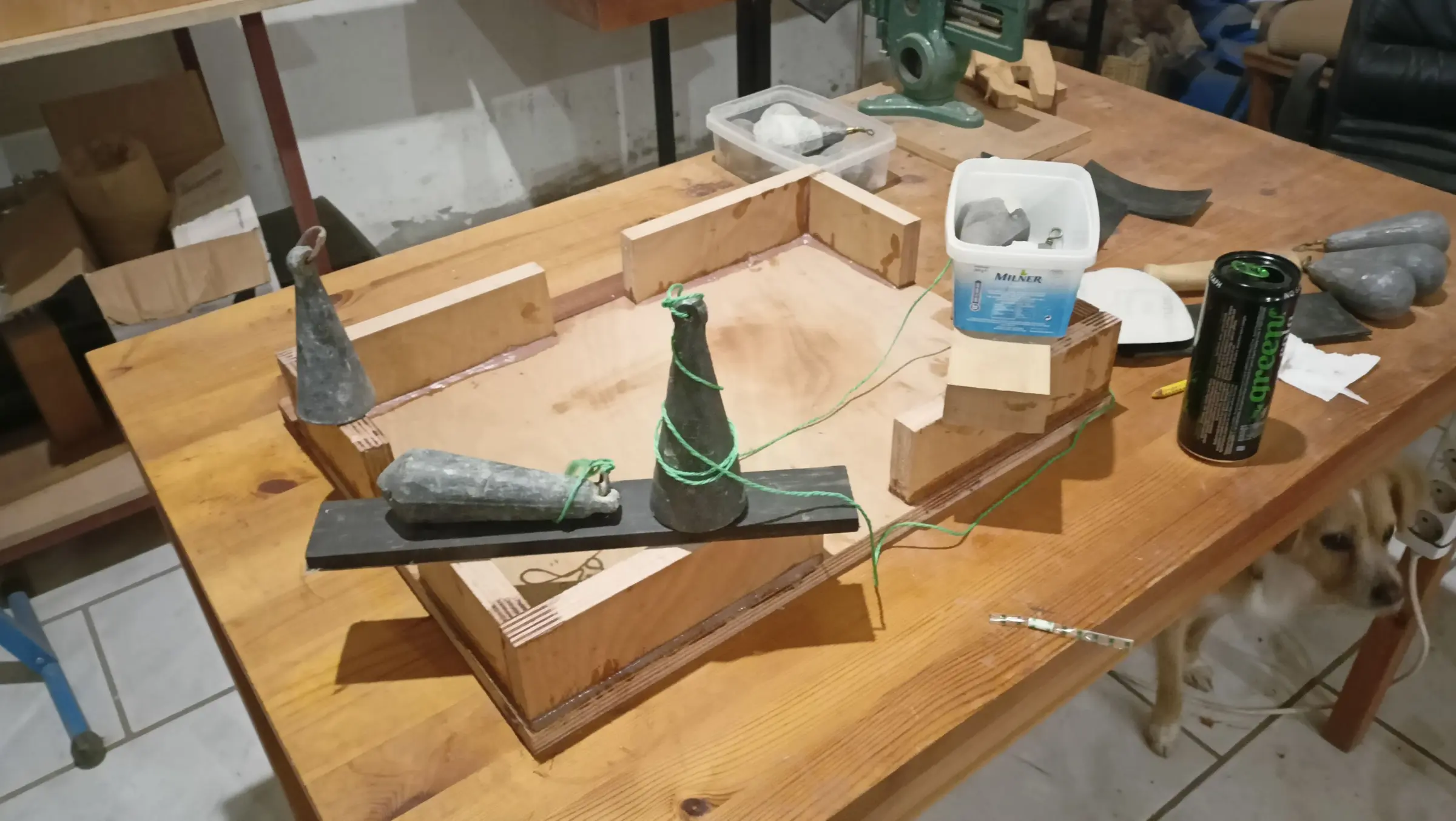
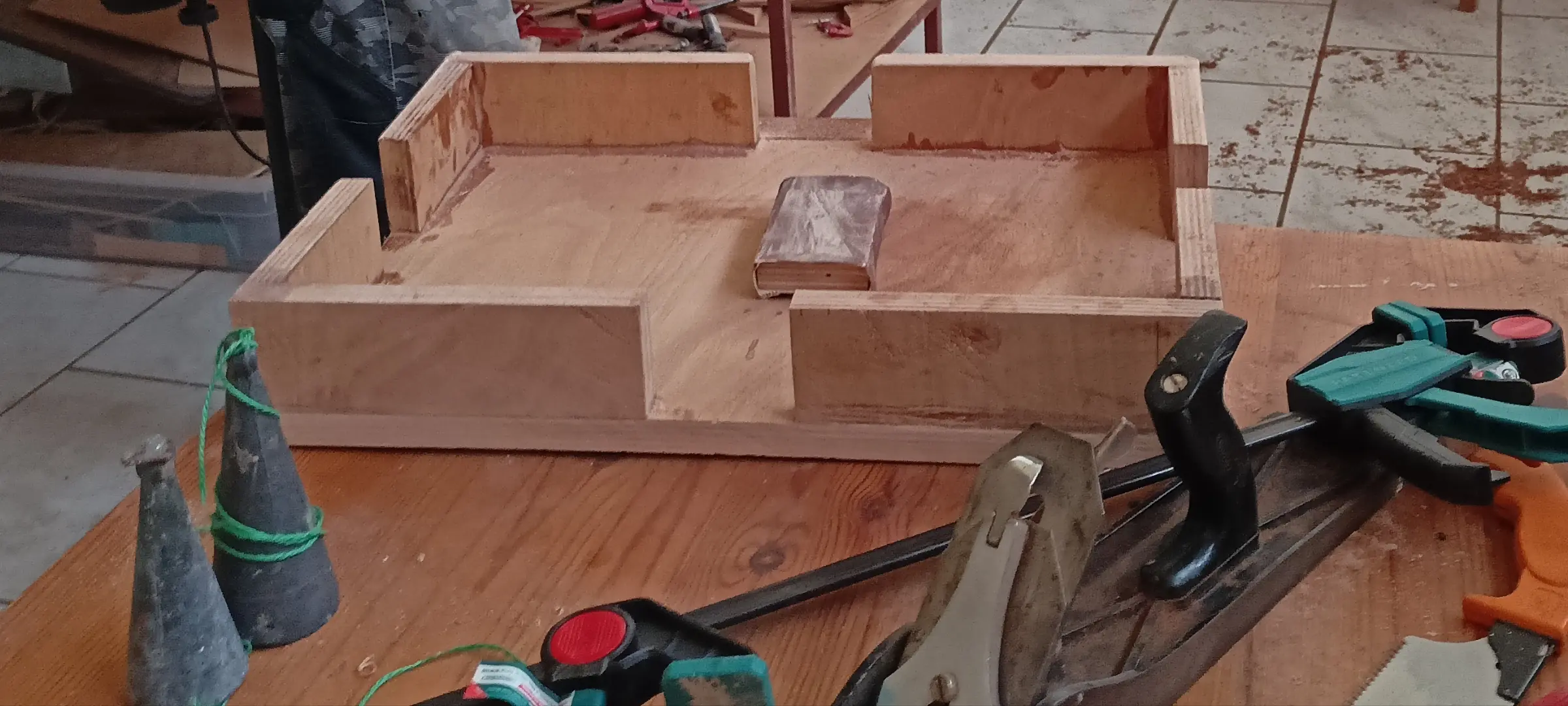
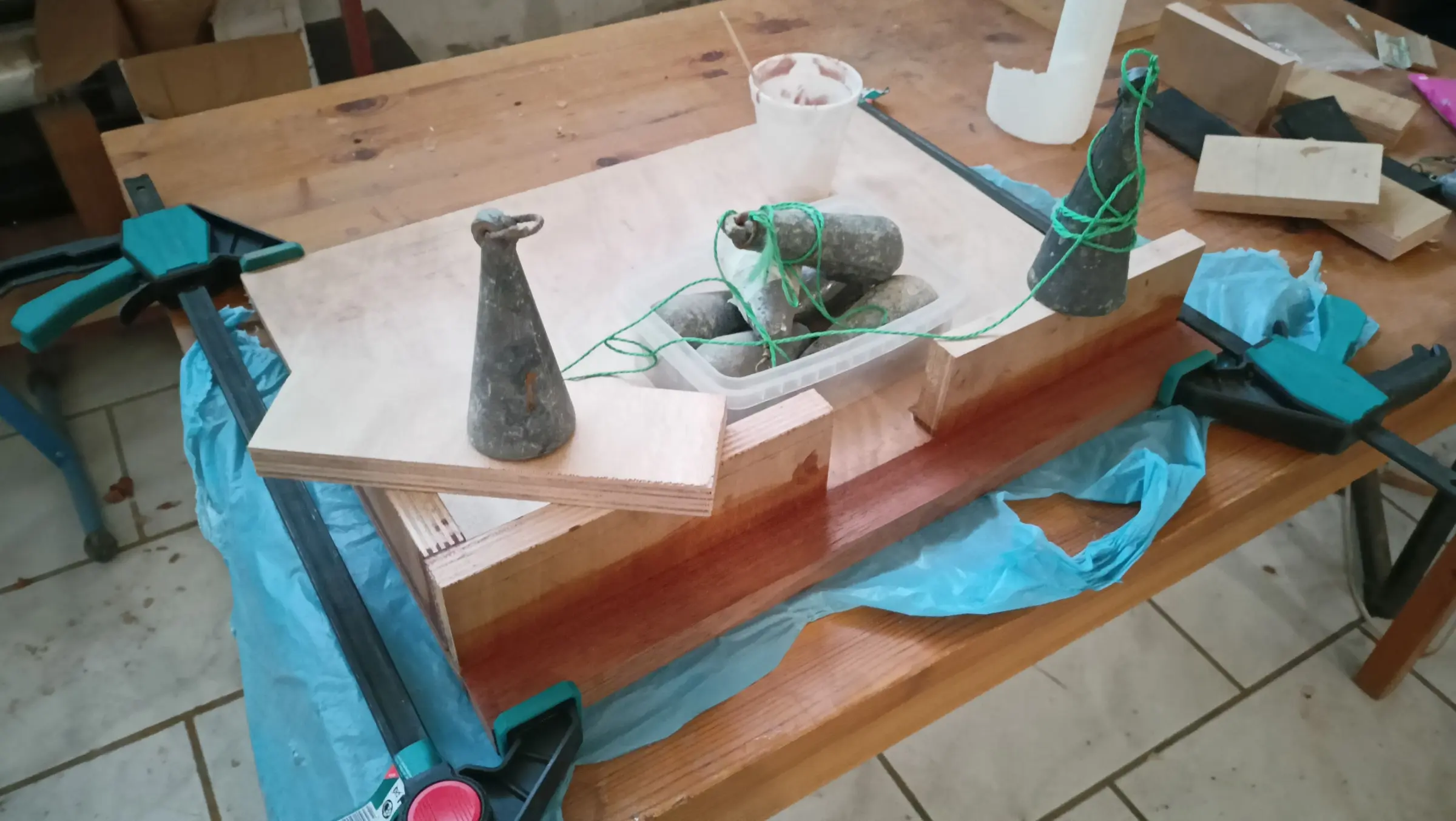
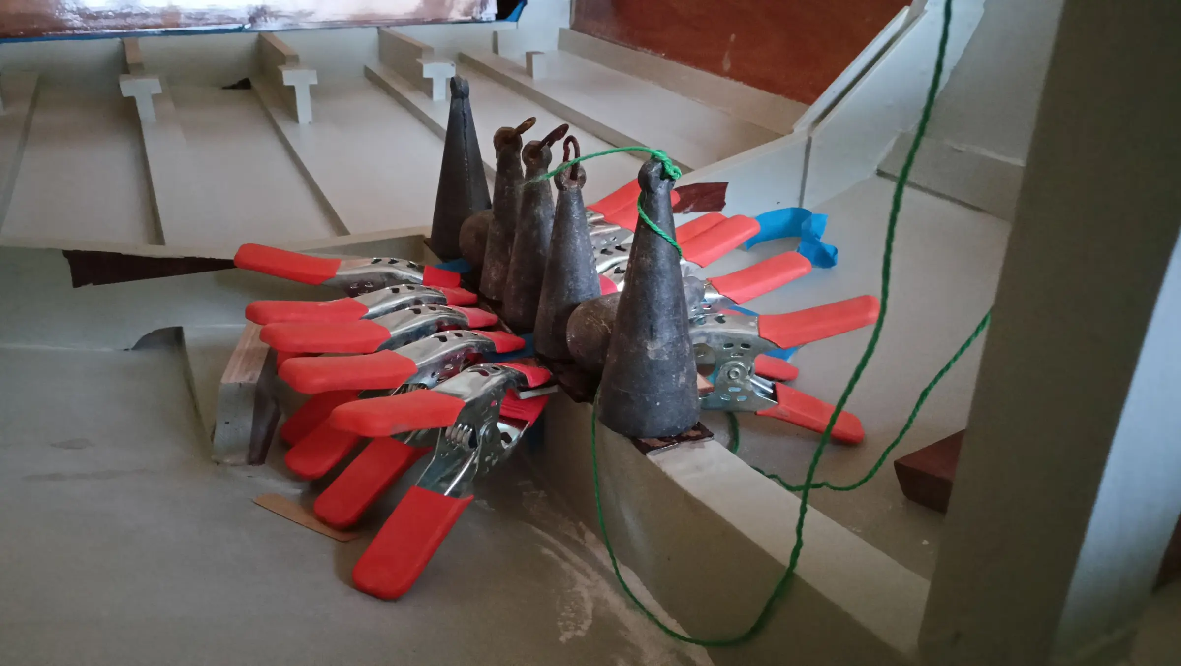
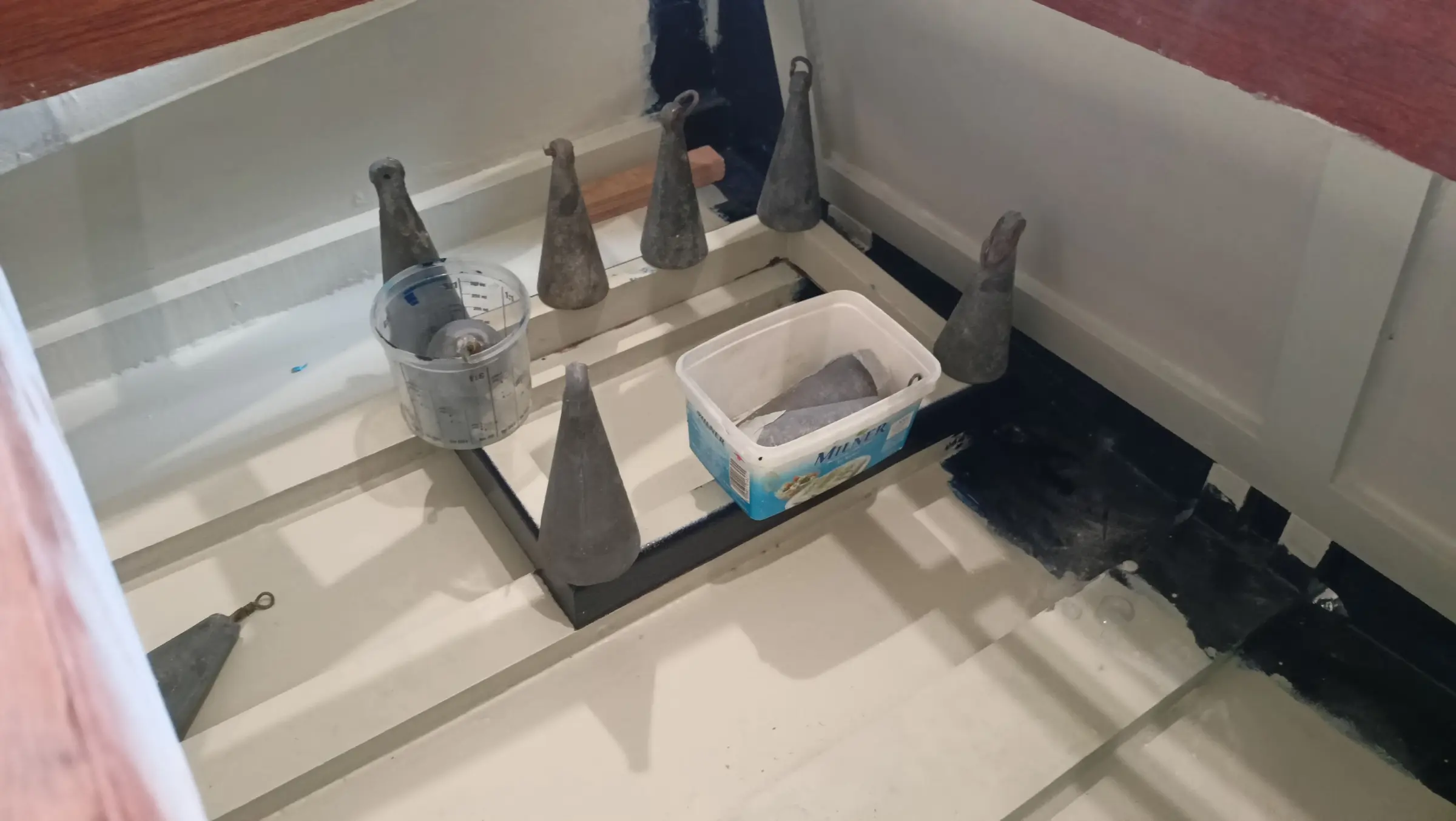
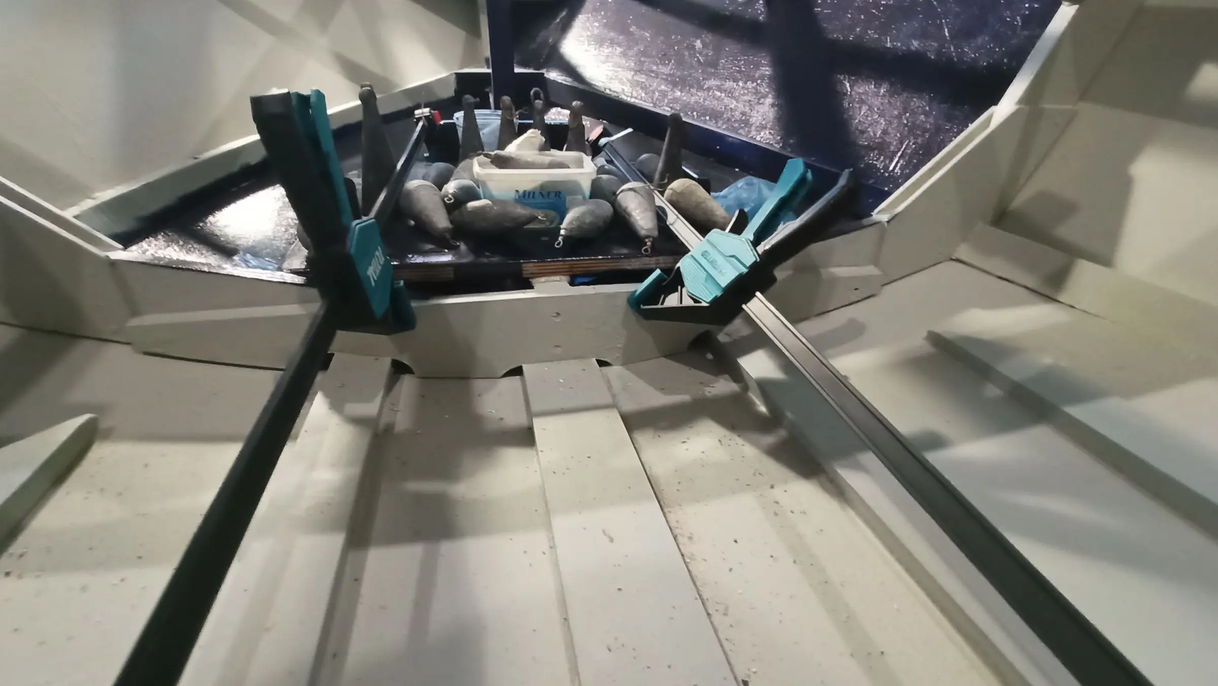
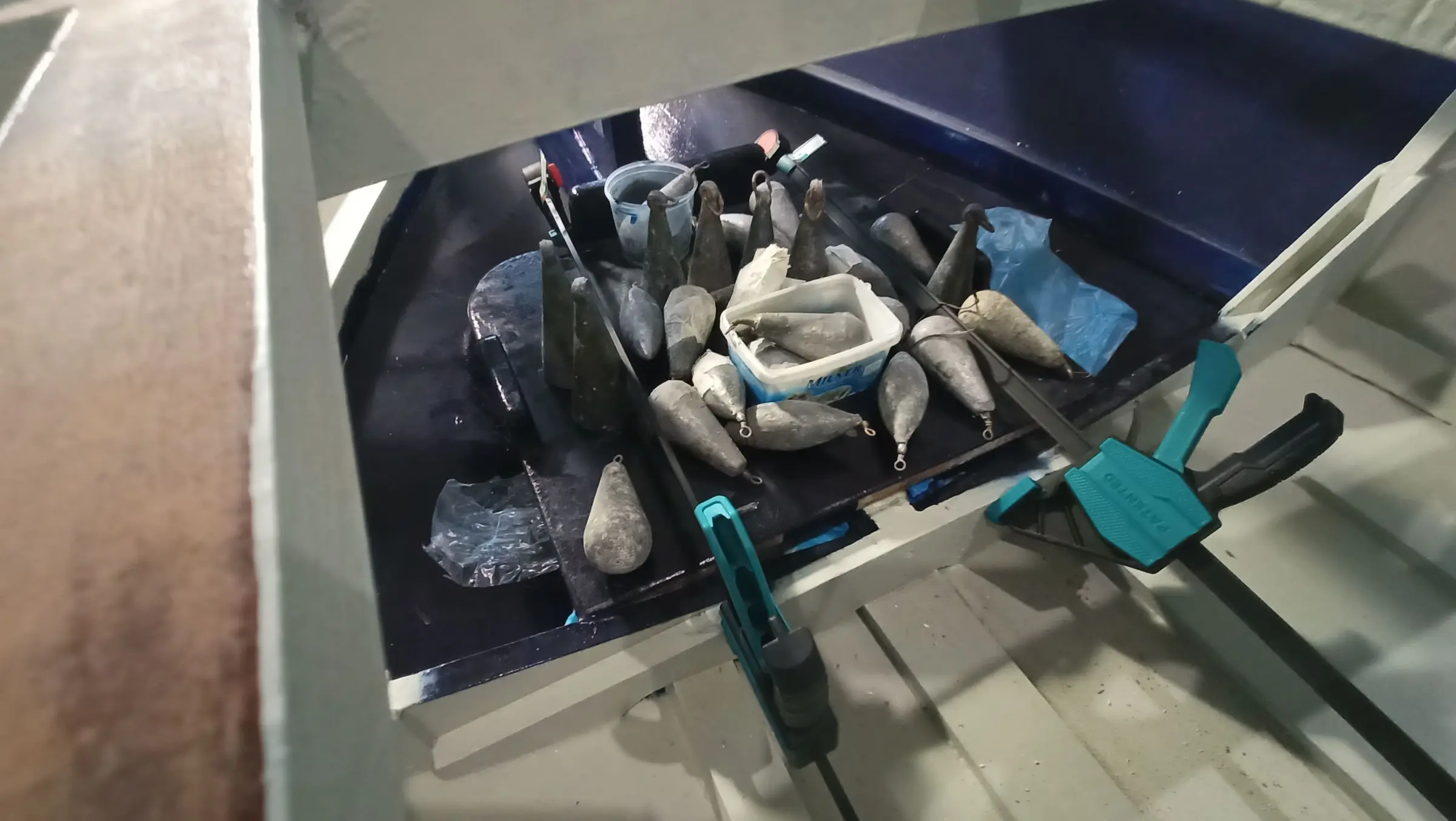
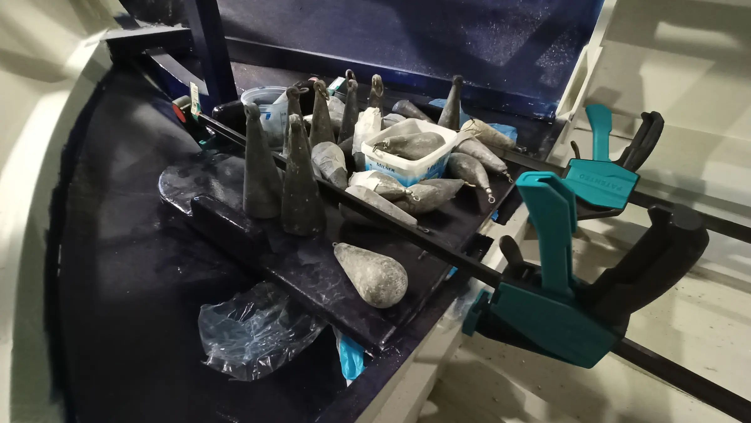
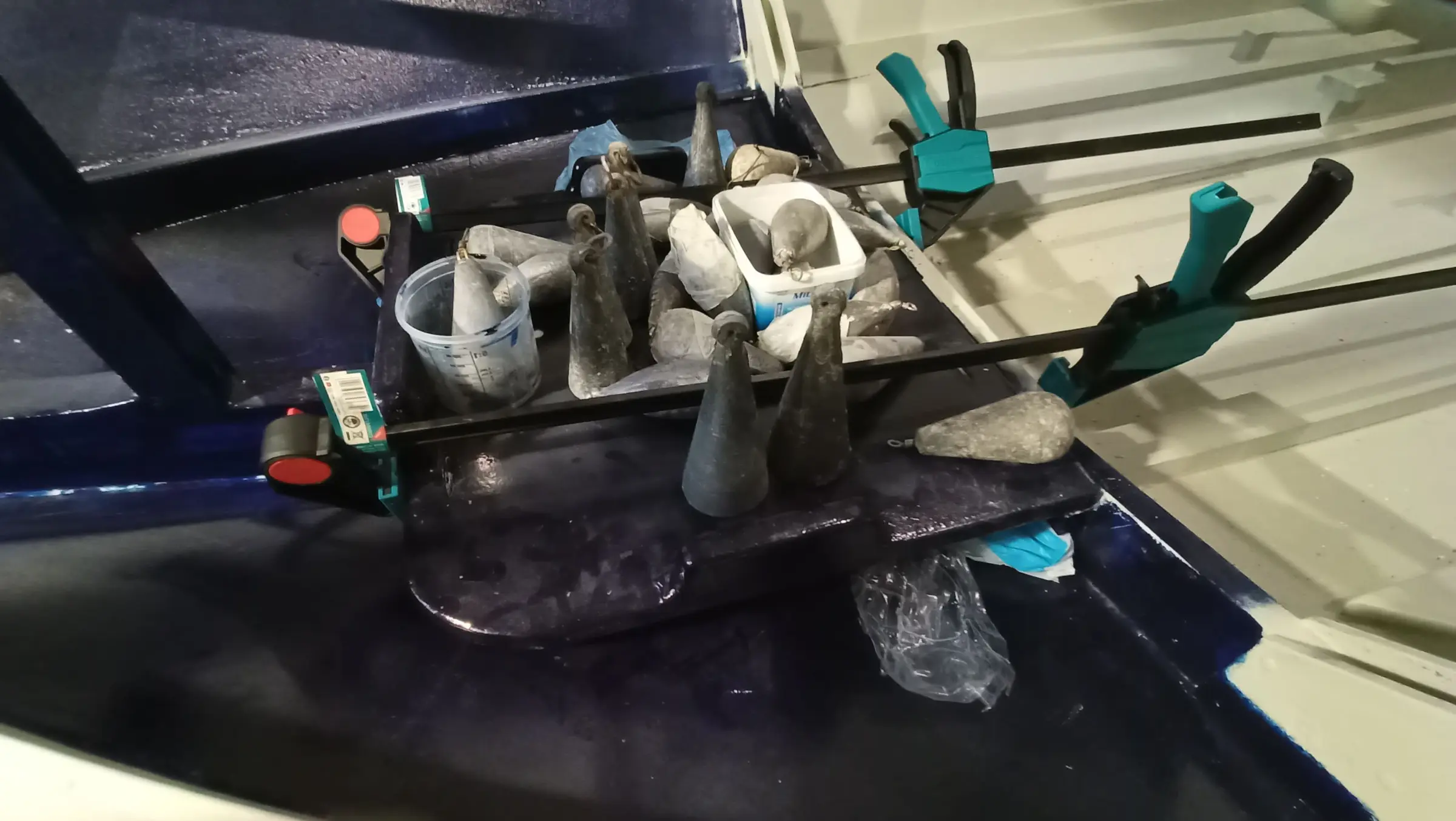
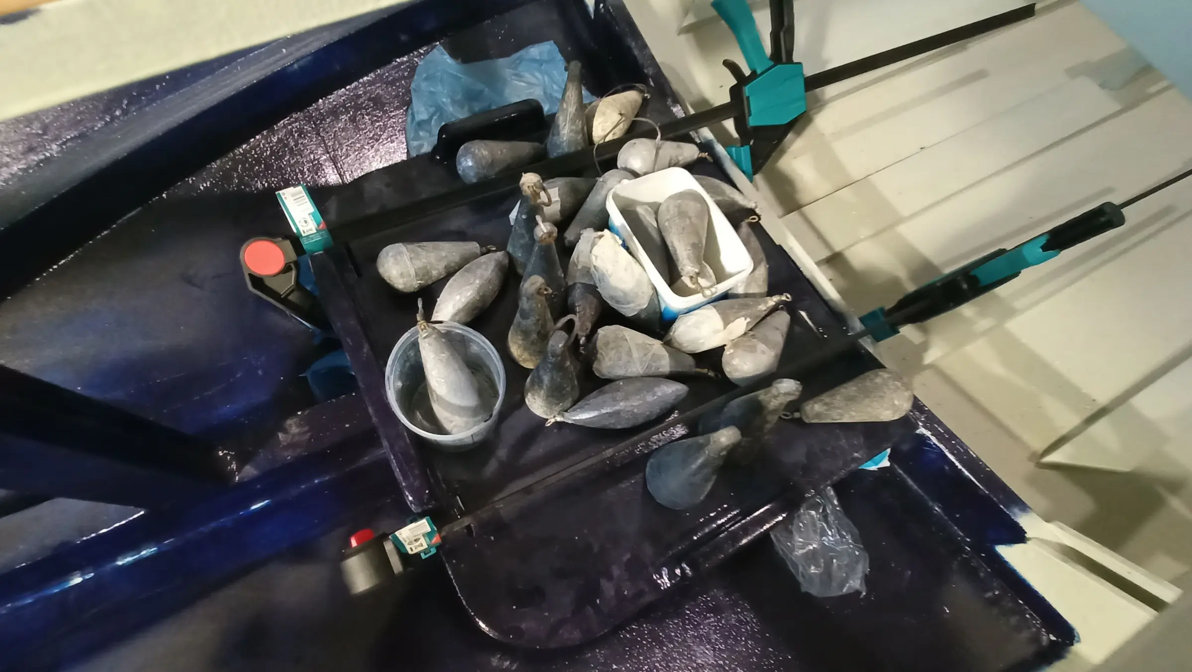
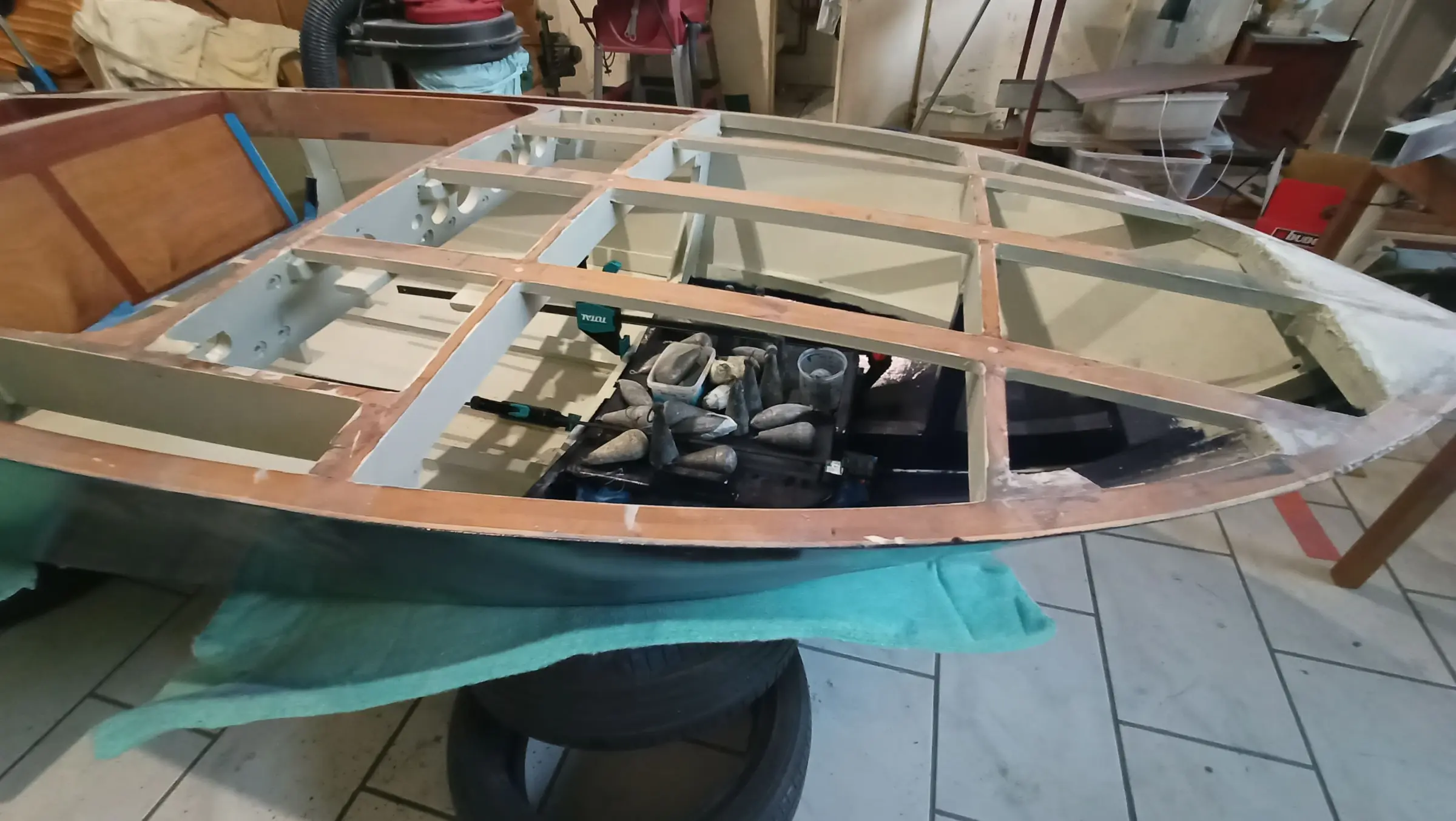
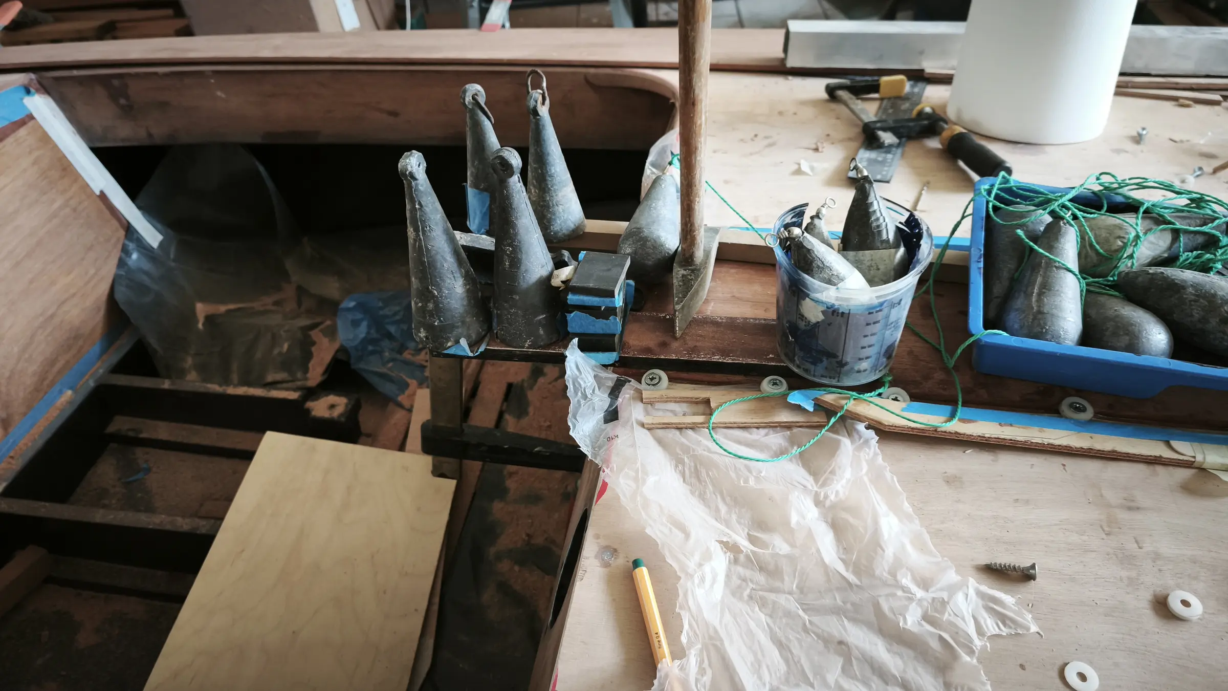
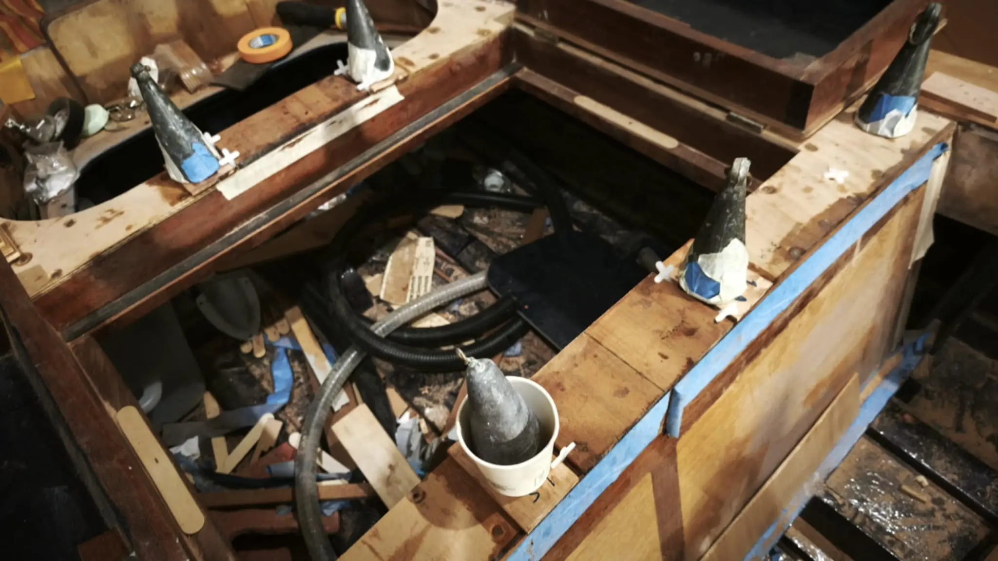
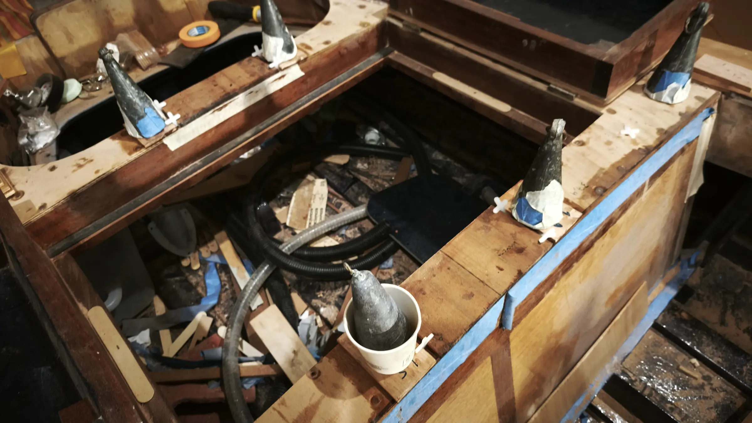
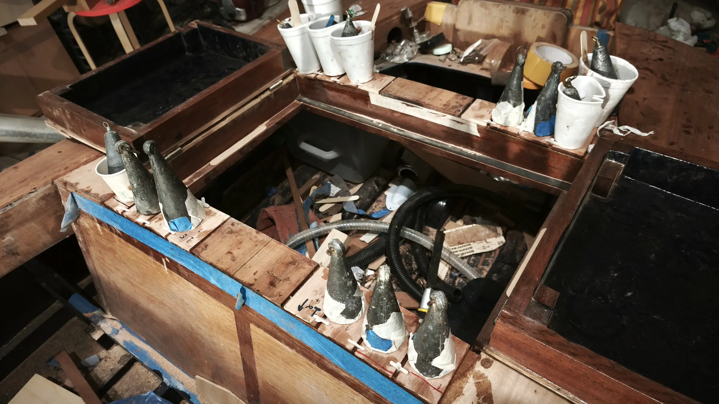
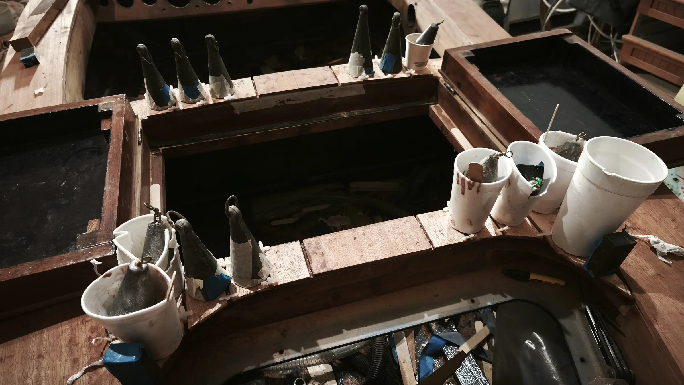
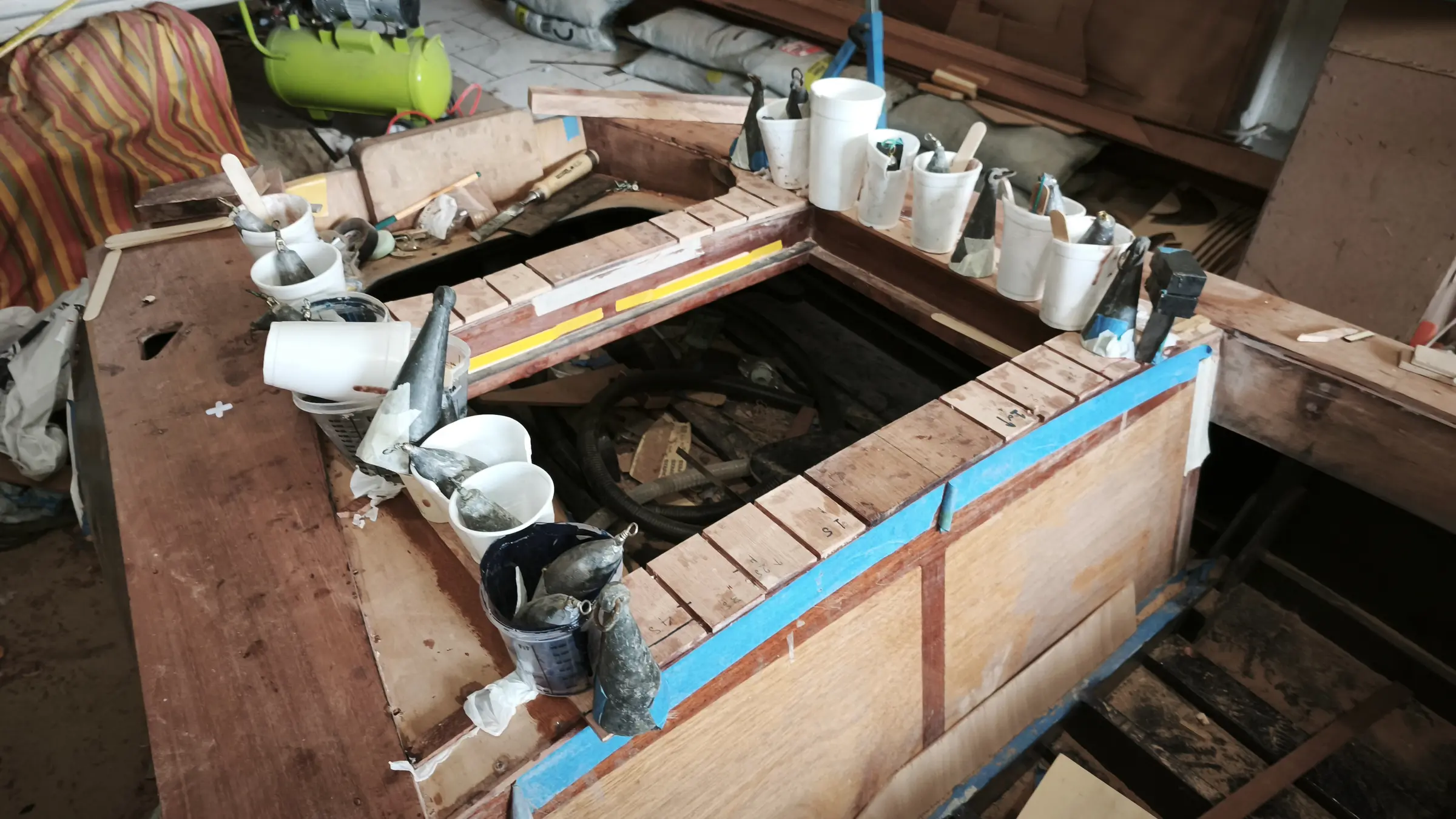
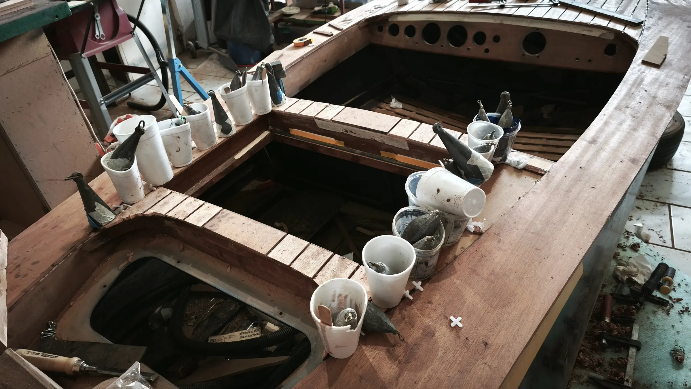
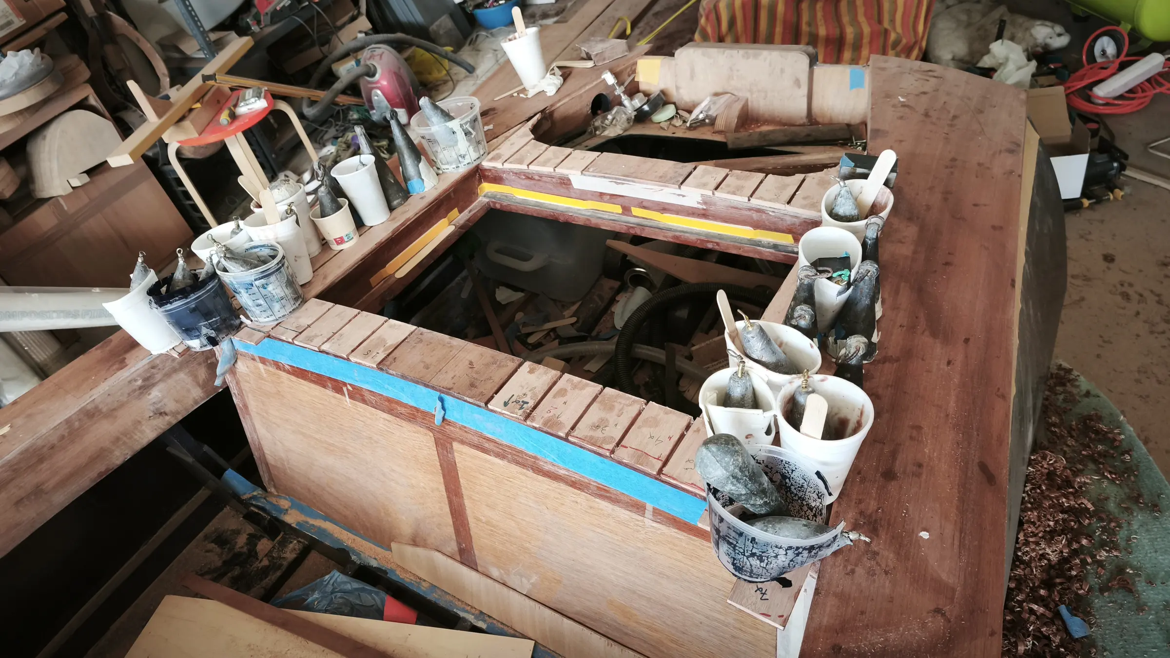
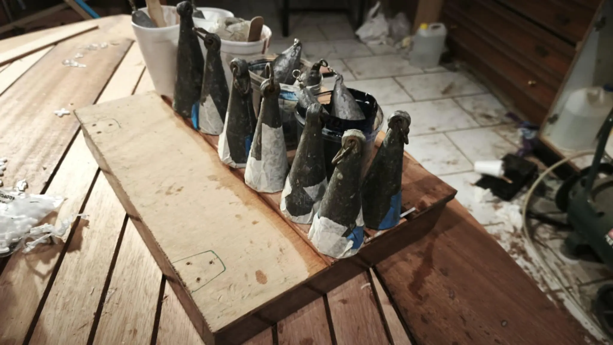
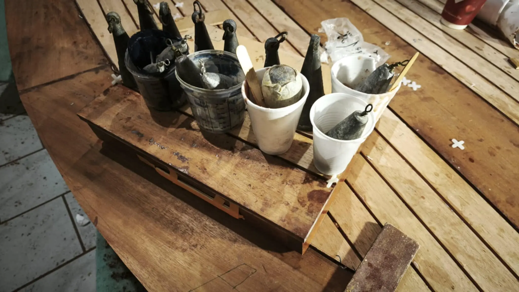
Large clamps were bought and fishing weights were used for pressure.

The next job was fitting the locker behind the seat. The locker frame stands about 3 mm off the sides of the boat (two thin sticks, tongue depressors) and about 5 mm between the left and right halves. I decided to leave about half that margin as overhang on the lid. Some photographs of the process.

So the locker doors could be screwed on, reinforcements had to be glued both to them and to the boat's framework. The process is below.

The holes for the forward and aft mooring cleats were drilled properly.

The next job, which needed a good deal of thought and study, was the correct position for the stainless fittings (cleats, rowlocks and so on) on the top of the boat. The problem I ran into was that because of the control box I could not put the rowlock very far forward, so that it would be in the right place for comfortable rowing when I am sitting on the seat back. The right position would be about 40 to 50 cm forward of where I sit. That was not possible and it will go a bit further aft, about 30 cm. So a reinforcing block was glued in so the structure will take the load from the oars.

At the forward end, the stainless fittings and the red and green light will be installed as in the photograph below. Only the fuel filler cap is missing, which will go directly above the tank.

For the horn, as can be seen in the photograph, two small blocks had to be glued in for the screws to go into. I decided the horn should go at that point and well forward of the dashboard, so that a spray guard can be fitted if I decide on one.

Finally (much later, but I am showing it here) two thin pieces were glued on to increase the width, in case I wanted the stainless fittings I am going to use to be flush mounted.

The seat installation was finished. All that is left is to tidy the bolt holes up a little with the router. To get the insert to sit at exactly the right height I made the arrangement below. I filled the hole with epoxy and pushed the insert in, having first sprayed the insert, bolt, washer and nuts with silicone spray so they would not stick. That way a thread was formed in the epoxy and I can take the insert out at some point if I want to. I do not think it will ever be needed as it is stainless, but the option is there...

Finally I laser cut the stainless fittings for the aft end (left and right).

With all the interior work finished, the whole hull was painted.

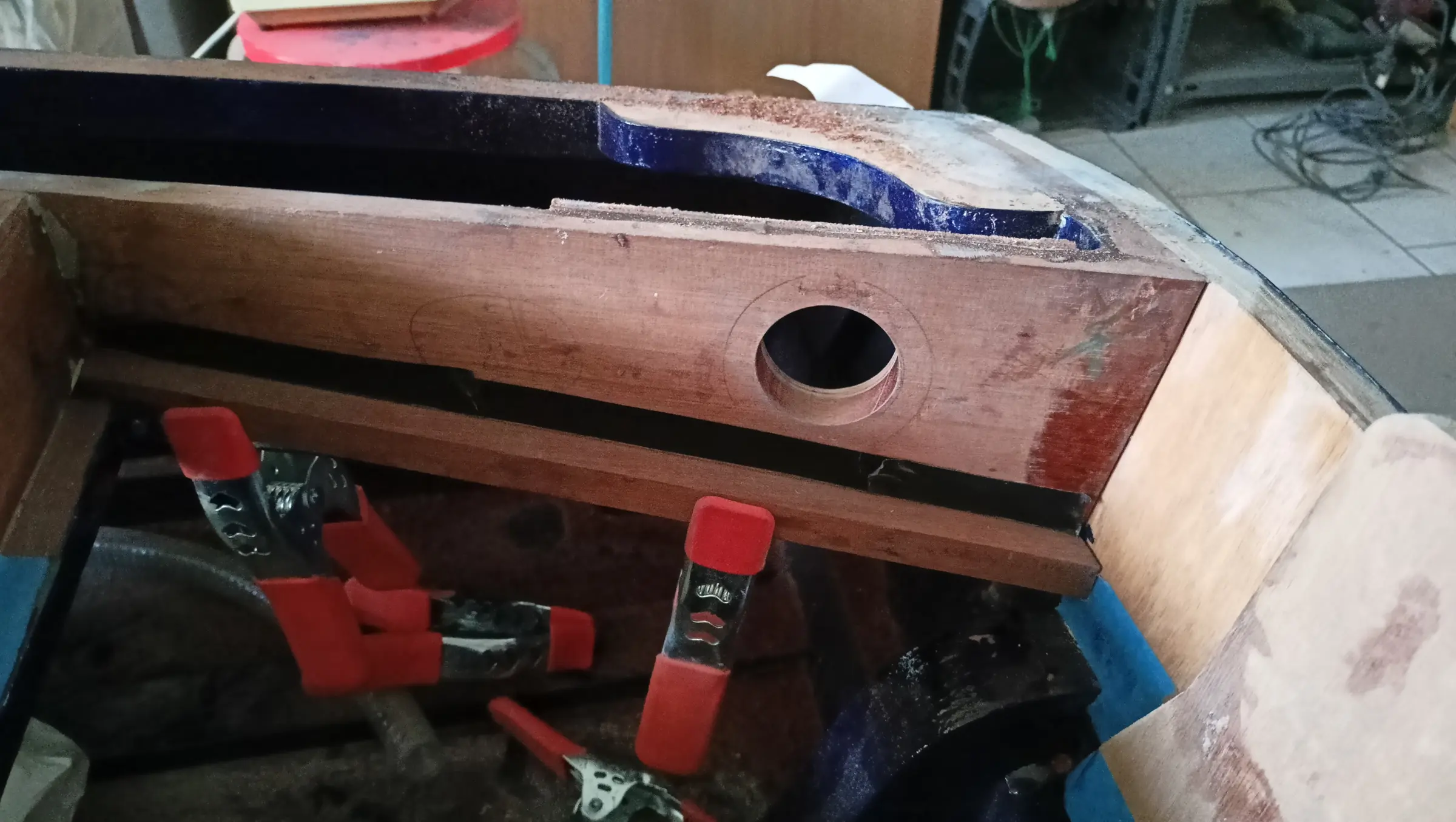
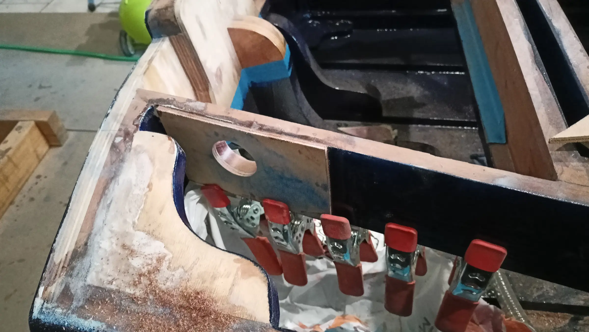
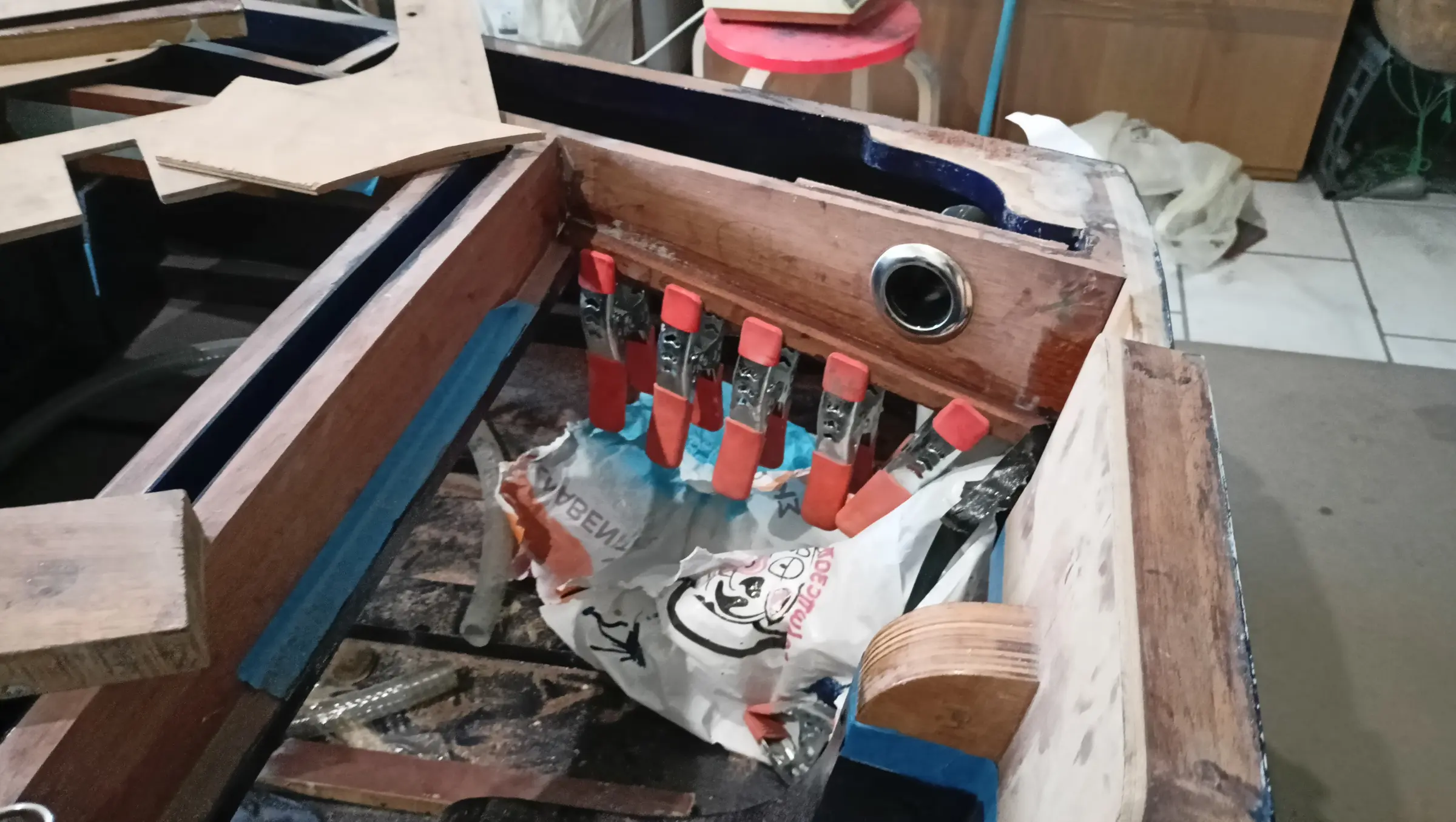
Then a hole was cut aft where all the outboard cables will run forward (control box, battery, steering cable and so on).

The next job was gluing in the aft locker. First, thin pieces had to be glued round the edge for the plywood to sit on.

The plywood was laser cut to the shape below.

The next job was gluing it in.

Once it was glued I also glued on the second curved piece above the plywood, which the "deck" will sit on.

The last job before gluing on the plywood for the top of the boat was drilling two holes for the steering cable to pass through. I have not kept a photograph of the finished result. The diameter is about 20 mm.


Fitting the flotation material

  1. Introduction

Ensuring the boat is unsinkable is one of the most important safety considerations in building a small craft. The term "unsinkable" does not mean the boat cannot take water inside it, but that even in the event of complete flooding it has enough positive buoyancy to stay on the surface.

Achieving that depends on installing suitable flotation materials, which act as a permanent reserve of buoyancy. These materials must stay effective for the whole life of the boat, must not be affected by the marine environment, and must retain their properties even after long use.

Just as important as the quantity of material is its correct distribution within the hull. The point of the flotation is not only to avoid sinking, but to maintain the boat's stability after flooding. Correct geometric distribution between bow, stern and sides helps keep the boat as close to level as possible (level flotation) and reduces the risk of capsize.

A conservative design approach is used in this build. The natural buoyancy of the wooden structure is not taken into account in the calculations, so that the flotation system has an adequate safety margin regardless of what the boat itself contributes.

  1. Analysis and choice of flotation material

The purpose of installing flotation material is to ensure the boat has positive buoyancy in the event of complete flooding. The choice of material is based on its resistance to the marine environment, its chemical stability, zero water absorption, its mechanical properties, and how easily it can be worked and fitted.

The following categories of material were considered:

Extruded polystyrene (XPS)

Extruded polystyrene was rejected, as it has no resistance whatsoever to hydrocarbons. Even a small quantity of petrol or other fuel causes rapid chemical breakdown of the material, so that it dissolves and loses its mechanical and buoyancy properties.

Polyurethane foam (PU)

Two-part polyurethane foam (pour foam) was rejected, because over time it can absorb moisture, increasing its weight and reducing its effectiveness.

Closed-cell polyurethane foam sheet was also considered. Although it behaves better with regard to water absorption, it is very brittle and stiff, so it does not conform well to the curves of the frames and it crumbles when worked.

Polyethylene foam sheet (PE)

Closed-cell polyethylene foam sheet was chosen as the most suitable solution.

The main advantages of polyethylene (PE) foam are:

Practically zero water absorption.

Excellent resistance to fuels, oils and chemicals.

High resistance to ageing.

Great flexibility, allowing it to conform easily to the curves of the boat.

Low weight in itself, as its low density allows a lot of net buoyancy per unit volume.

Easily worked.

Although it costs around ten times as much as the other materials, its reliability, durability and long life fully justify the choice.

  1. Theoretical background and calculation of the flotation required

According to Archimedes' principle, any body immersed in a fluid experiences an upthrust equal to the weight of fluid it displaces. In fresh water, each litre of displaced volume provides about 1 kg of buoyancy, while in sea water the equivalent is about 1.025 kg.

The calculations in this study are carried out on the basis of fresh water, which is the worst-case scenario.

The total mass of the metal fittings and permanent equipment is estimated not to exceed 100 kg, distributed roughly as follows:

Outboard engine: 56 kg

Lithium battery: about 4 kg

Steering, controls and other fittings: up to 40 kg

Before the flotation material is finally installed, all the components will be accurately weighed.

On the conservative assumption above (ignoring the buoyancy the wooden structure provides), a minimum of about 100 L of net flotation volume is required simply to offset the weight of the equipment.

For real safety, a safety factor of at least 1.5 is applied, setting the required volume at 150 to 180 L (or more, if the available space allows).

That choice ensures a significant reserve buoyancy, improves the boat's behaviour in the event of flooding, and ensures that, under the design conditions assumed, the boat will stay on the surface until a rescue is completed.

  1. Fitting process and geometric distribution

Correct distribution of the flotation material is as important as the total quantity. The aim is not only to stop the boat sinking, but to keep it as stable and as level as possible in the event of complete flooding.

Phase A, filling the bow

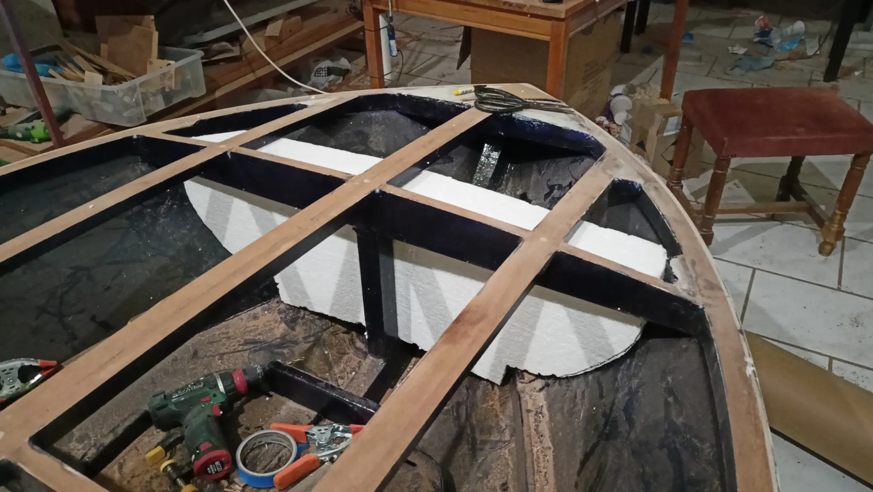
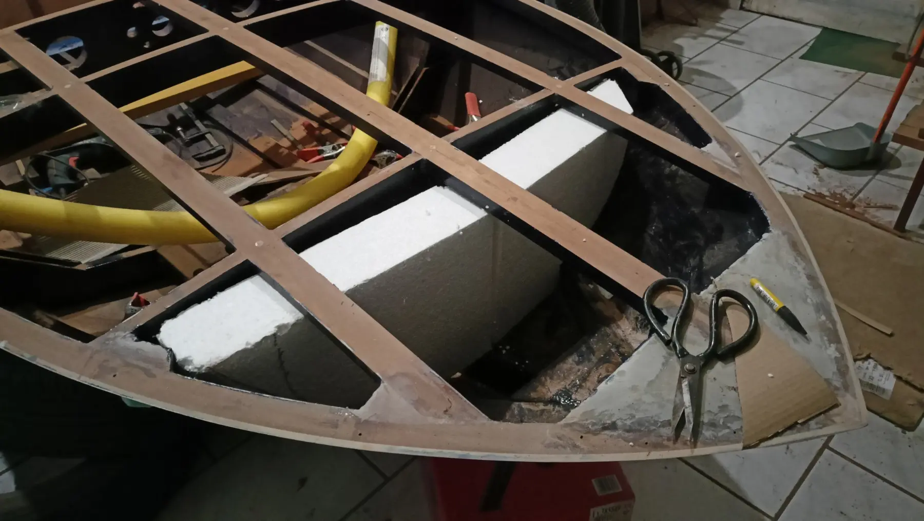
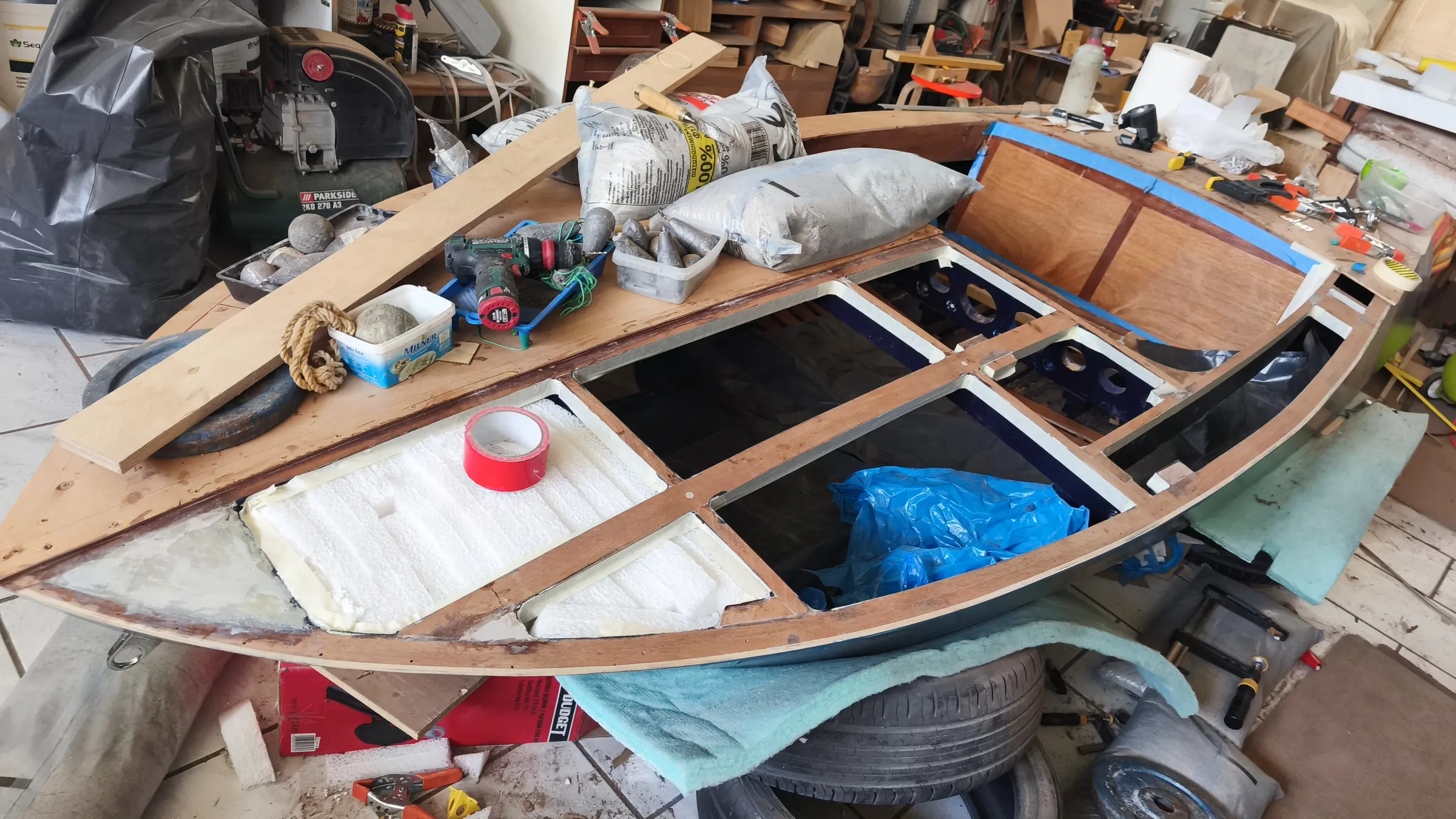
The bow is a sealed and inaccessible space (dead space). Since the next stage of the build is closing that compartment permanently, the polyethylene sheet has to go in before it is decked over.

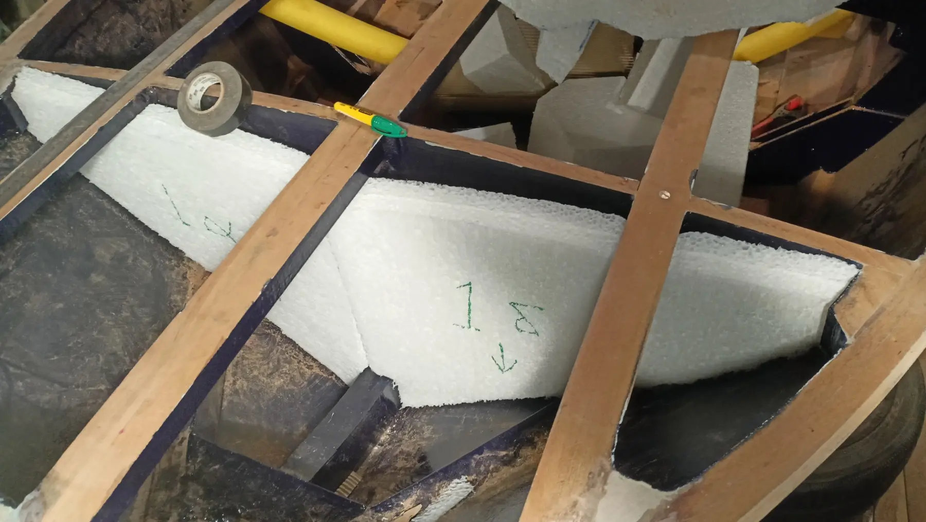
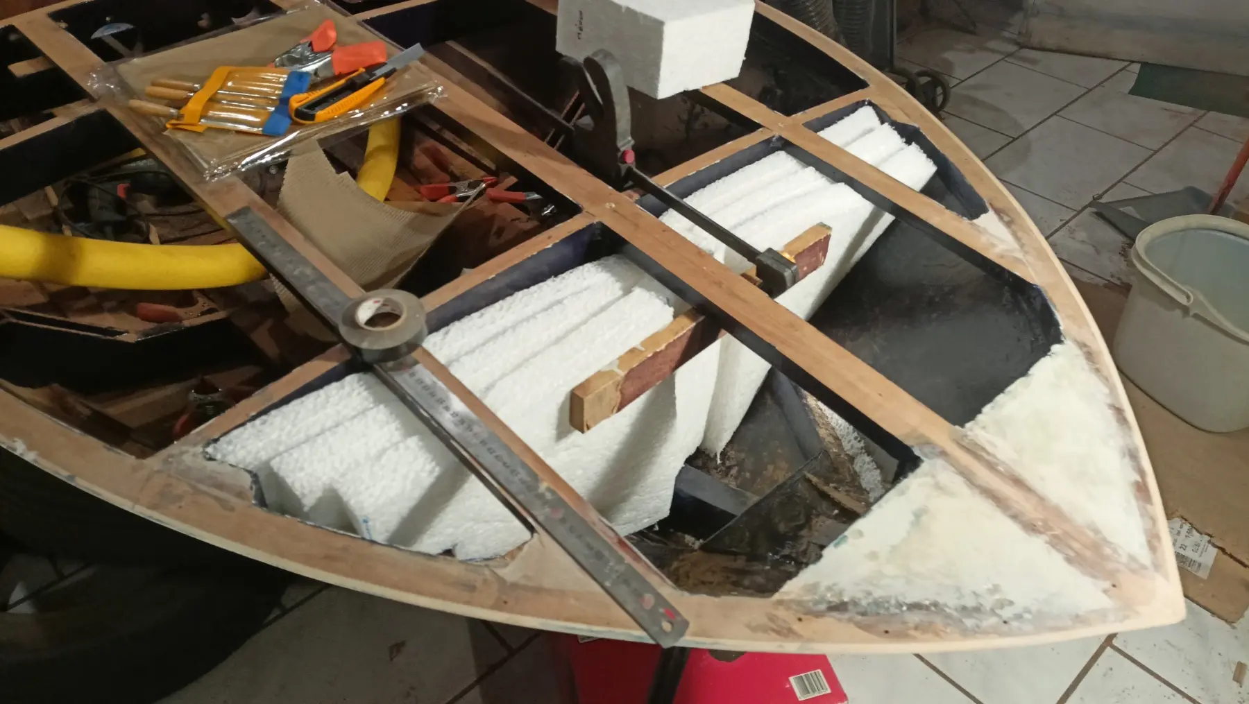
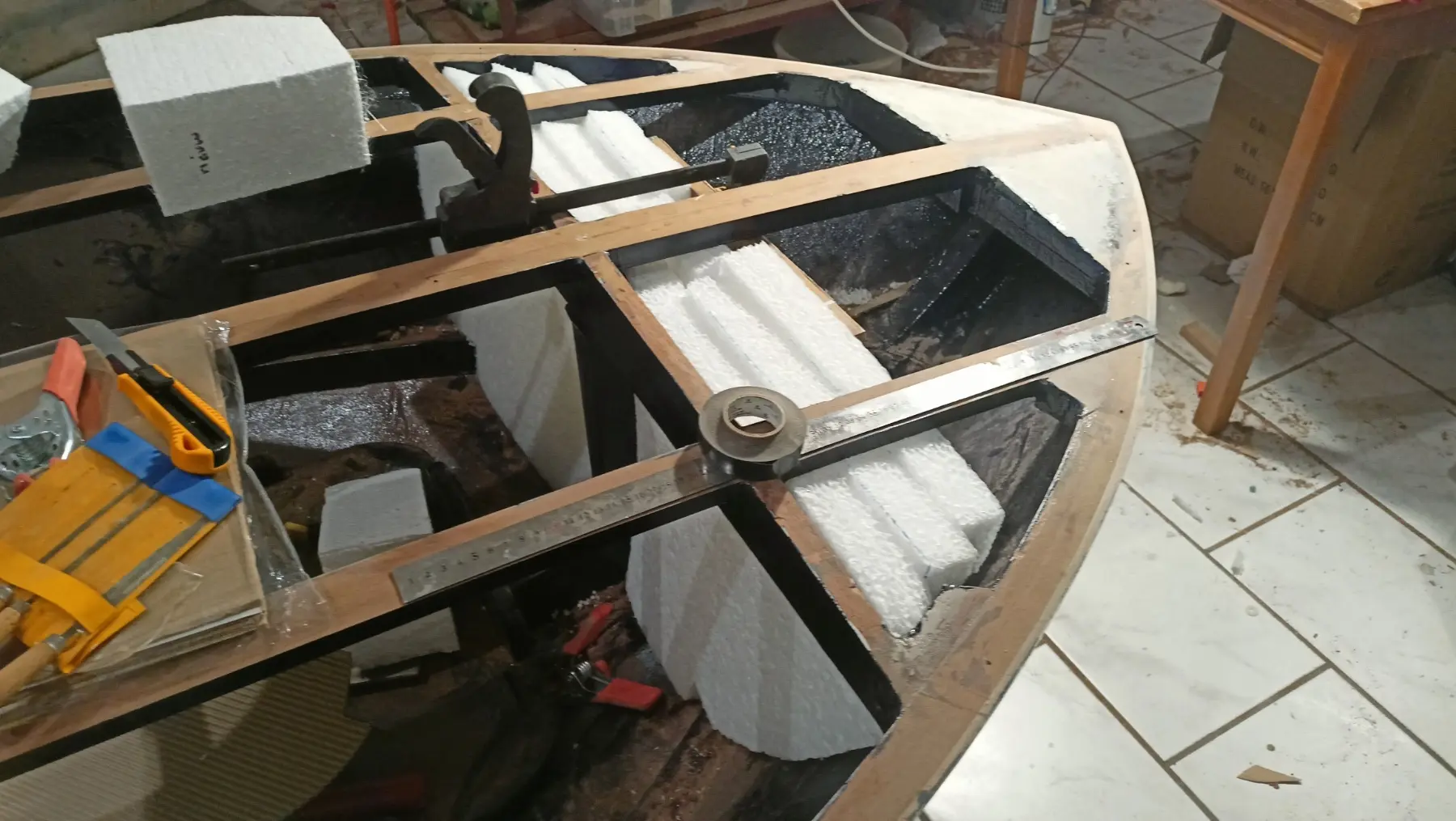
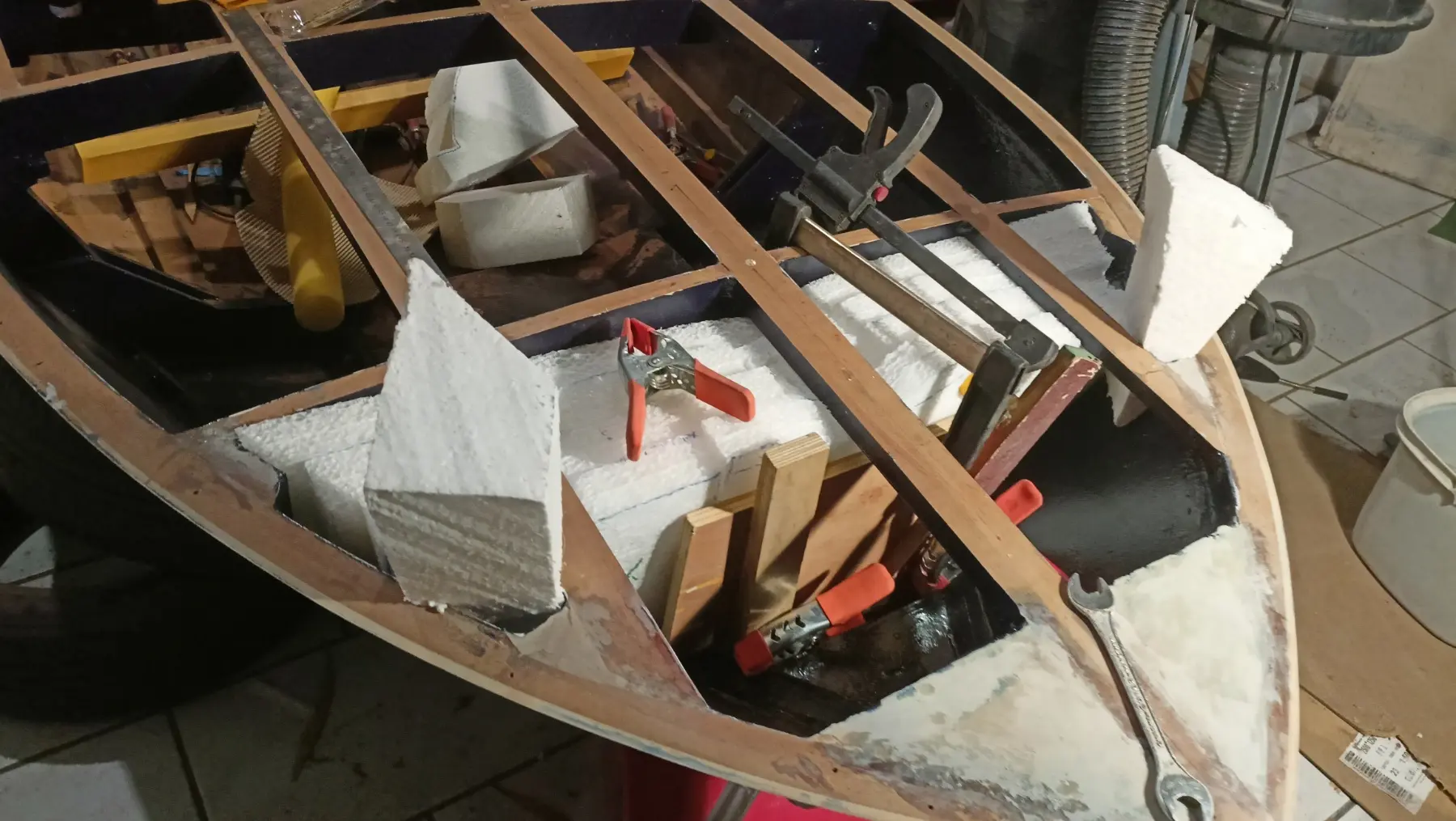
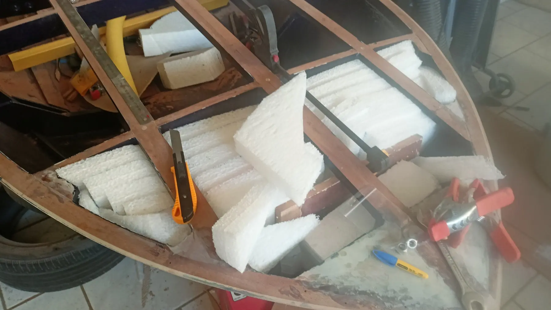
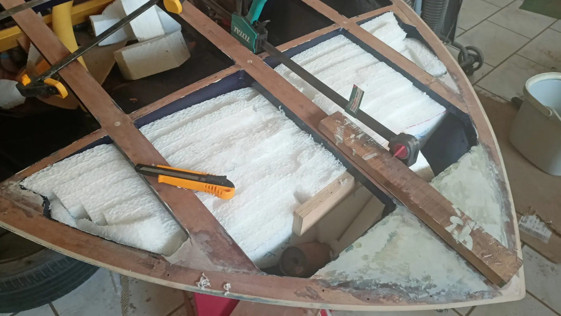
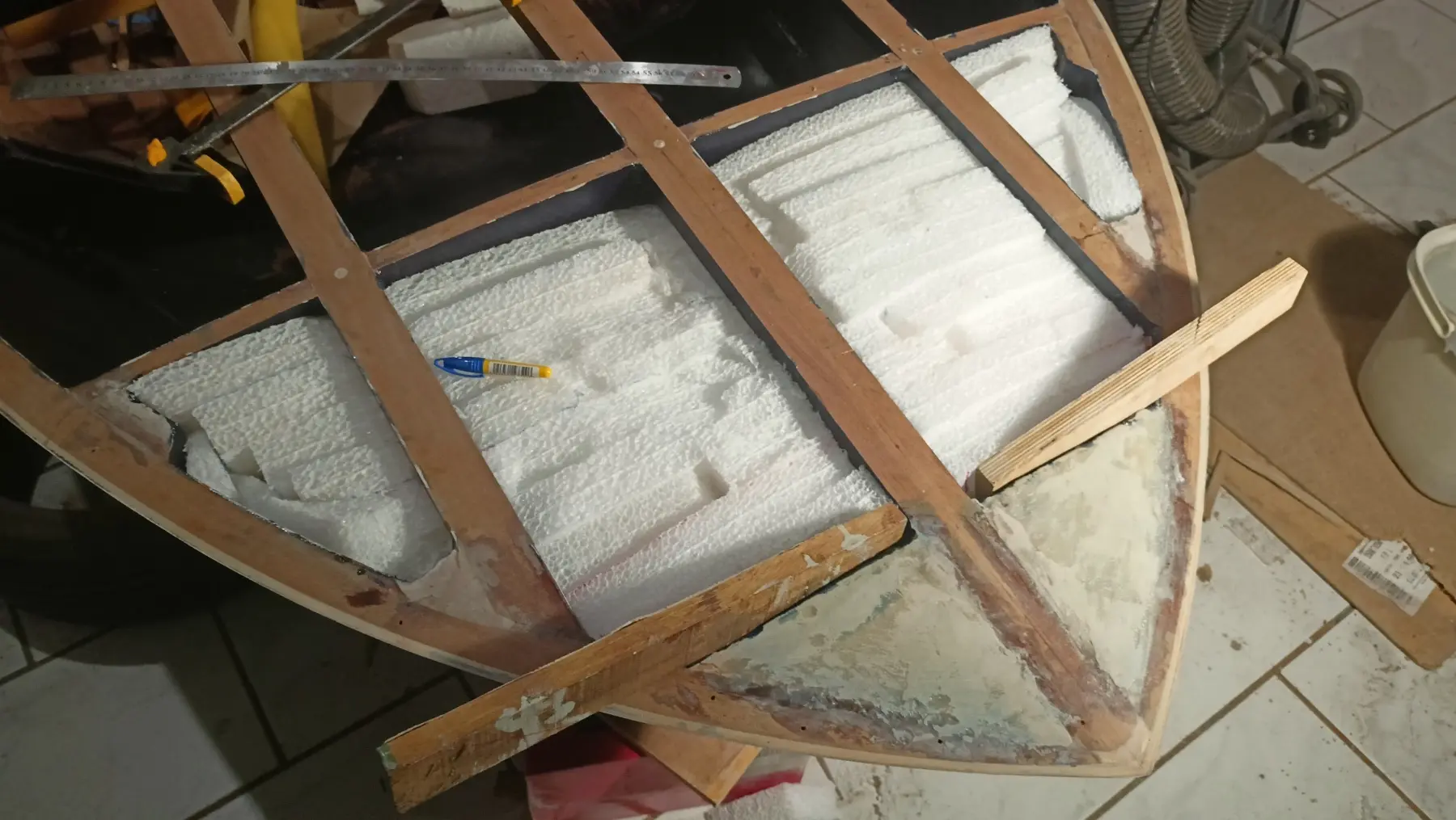
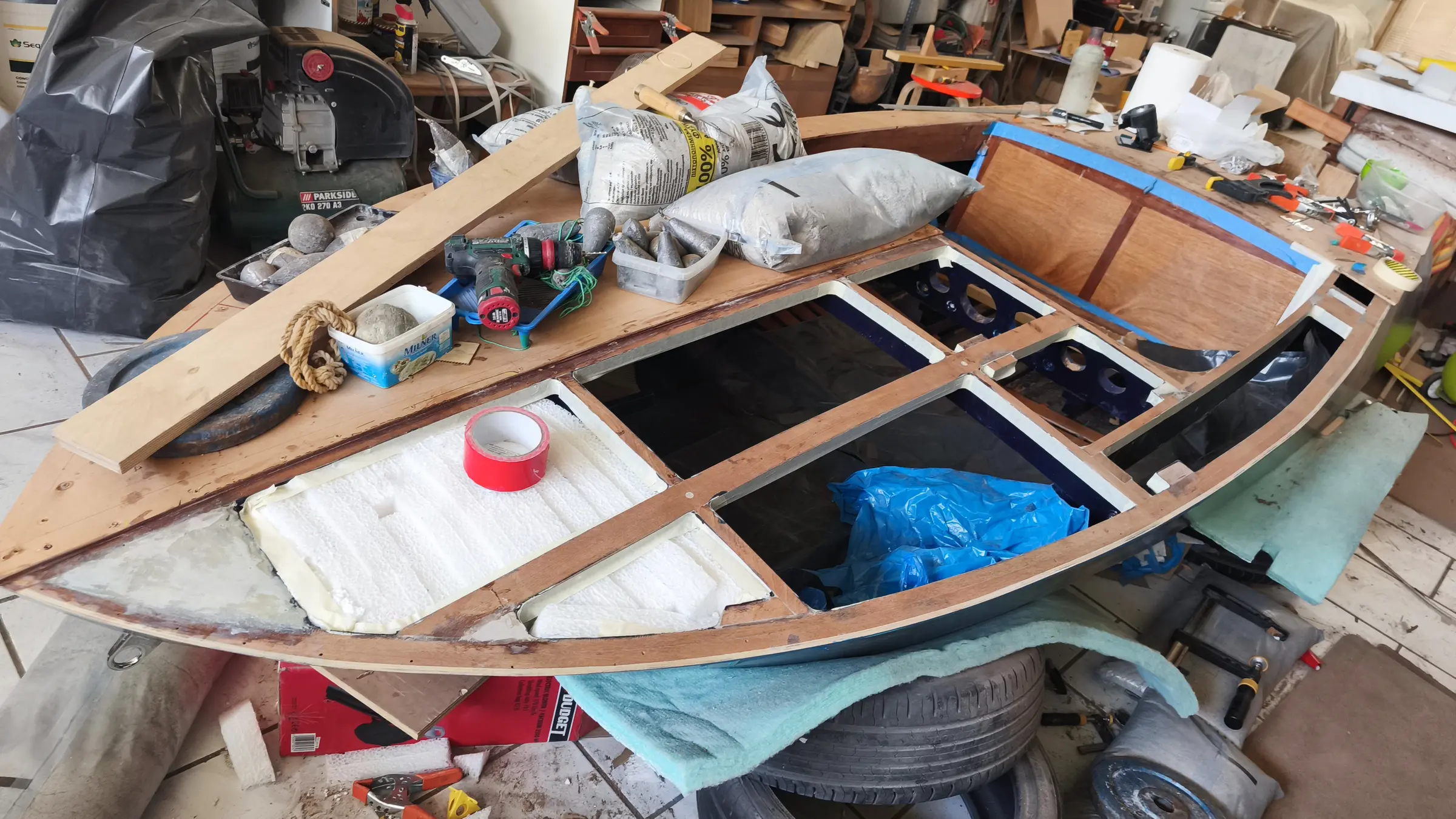
The available space was filled with as much sheet as possible, cut, fitted and wedged in, making sure it stayed put within the sealed volume. I put the sheets in layer by layer and glued them to each other. The result is a solid mass that cannot come out.

Before that, the stainless fitting for the mooring line was installed, because afterwards I will have no access.

Some photographs of the installation.

Phase B, reinforcing the stern

The stern carries most of the static load, mainly because of the outboard. For that reason about 50 to 60% of the total volume of flotation material will be placed either side of the motor well and under the aft benches.

That arrangement limits how far the stern settles in the event of flooding and helps keep the transom above the surface. This work will be done at a later stage of the build.

Phase C, distribution along the sides for stability

To improve transverse stability and reduce the chance of capsize, some of the polyethylene foam will be cut into strips and fitted as high as possible on the side walls of the boat.

That arrangement creates buoyancy at the sides, limits large angles of heel and helps keep the boat as level as possible (level flotation), even when the inside has filled with water.

The side flotation will be fitted once the main joinery work is complete.

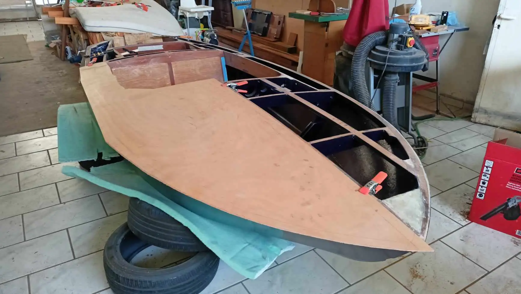
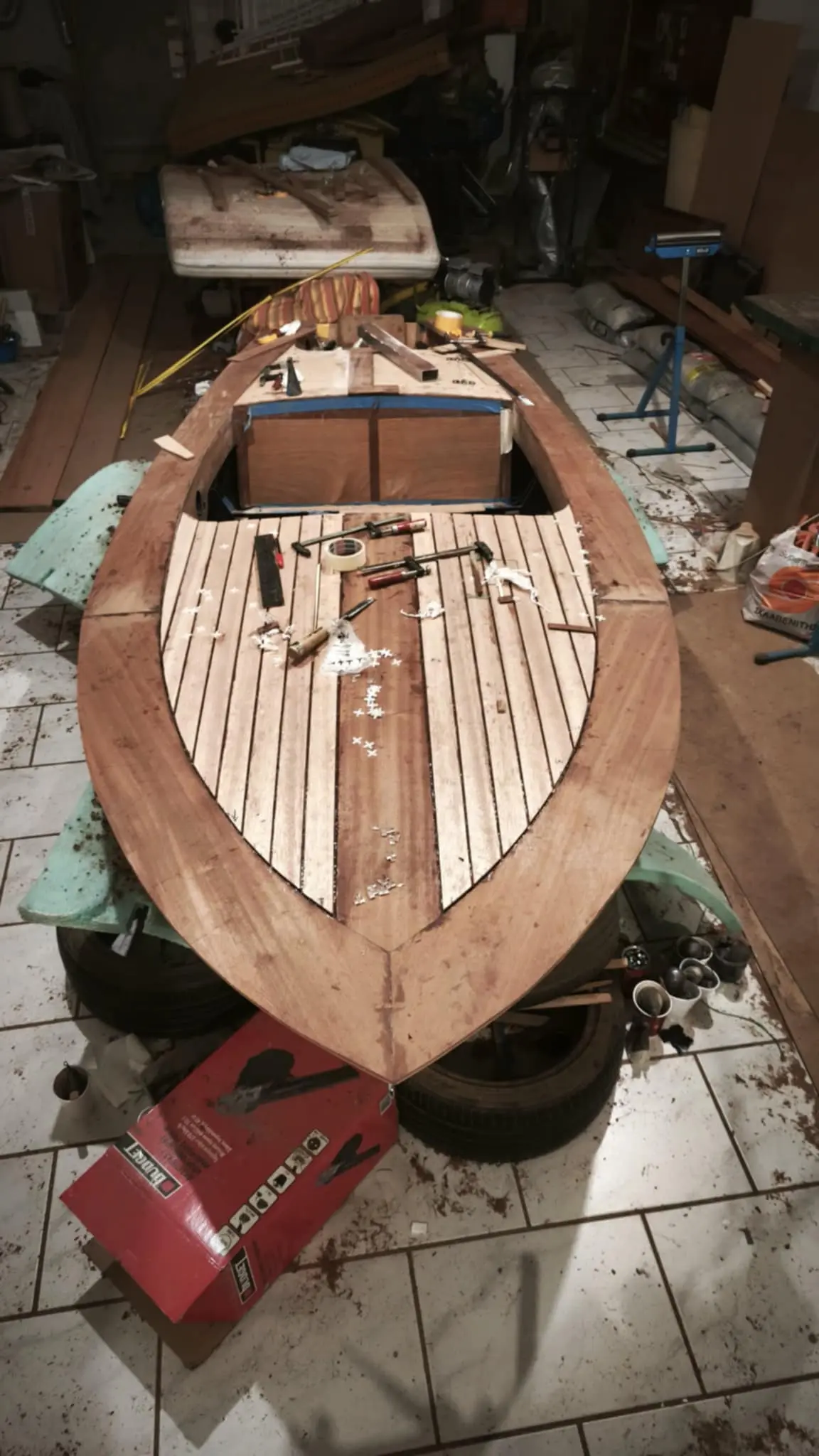
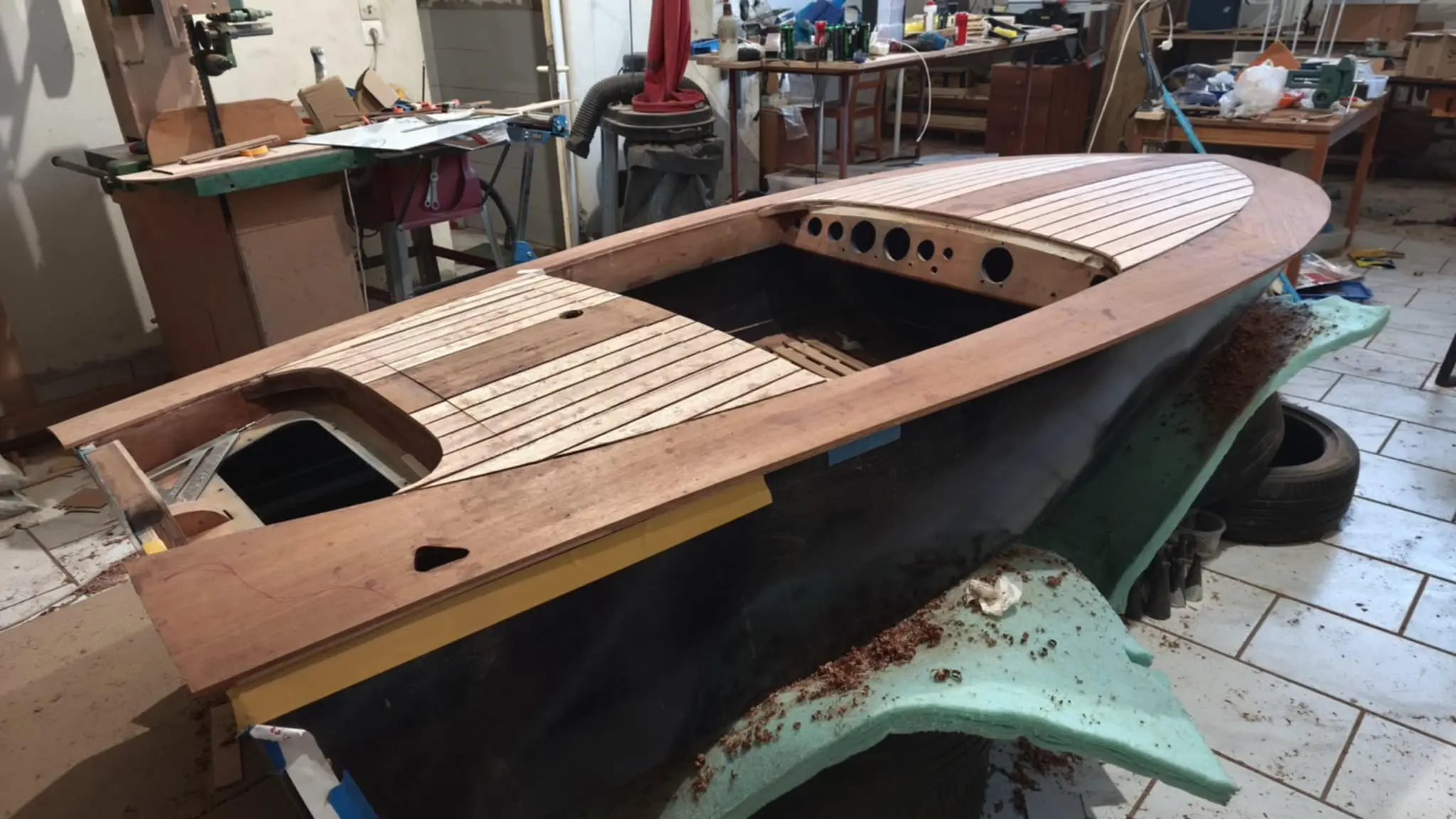
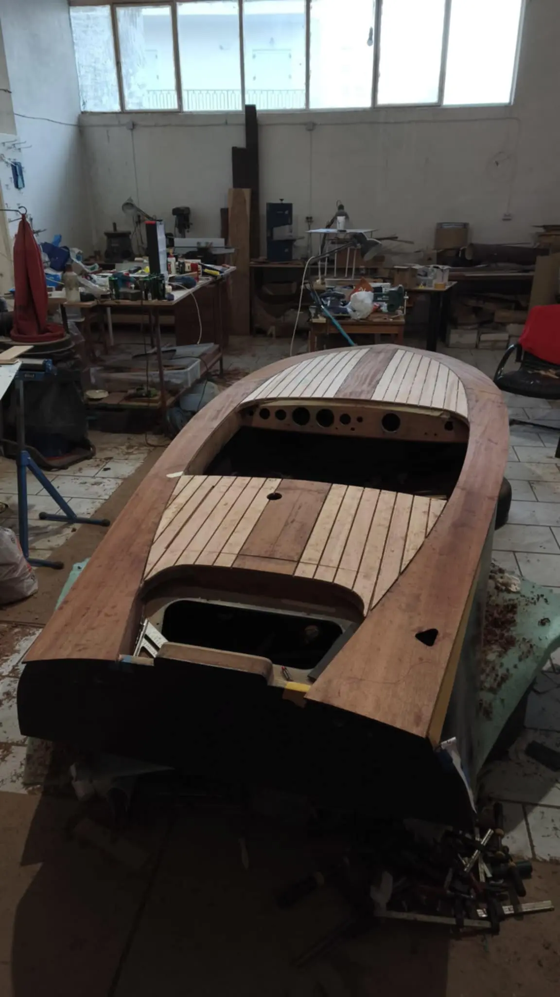
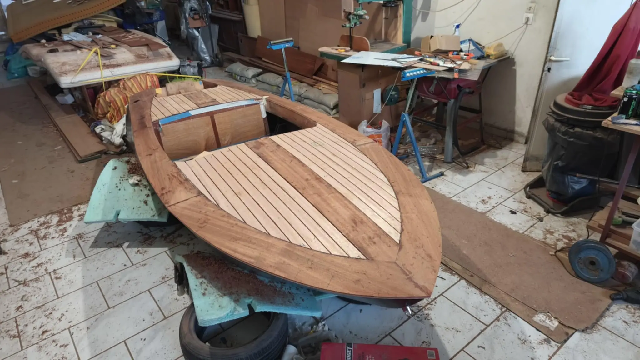
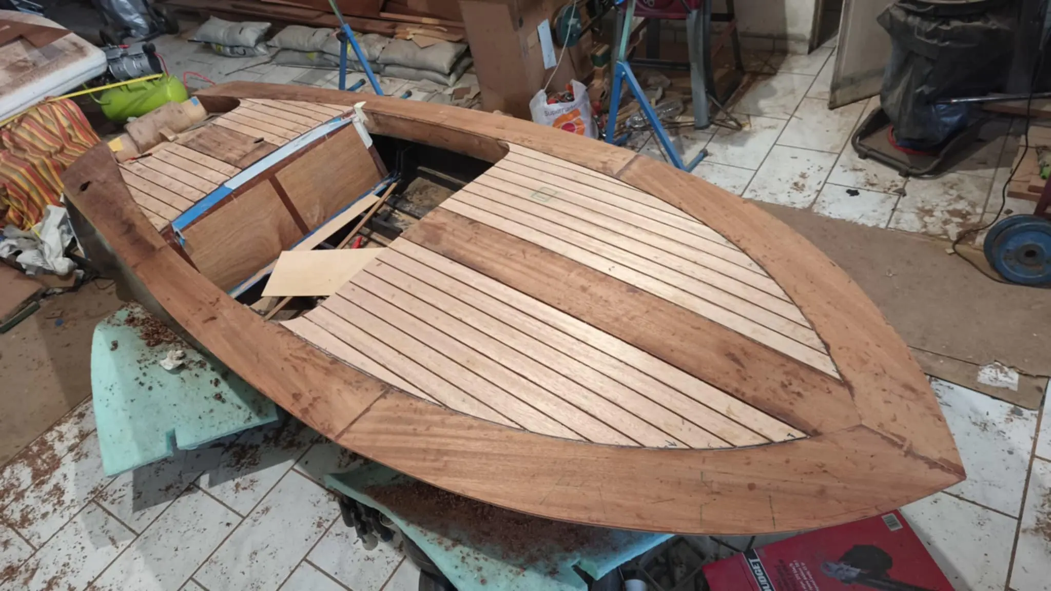
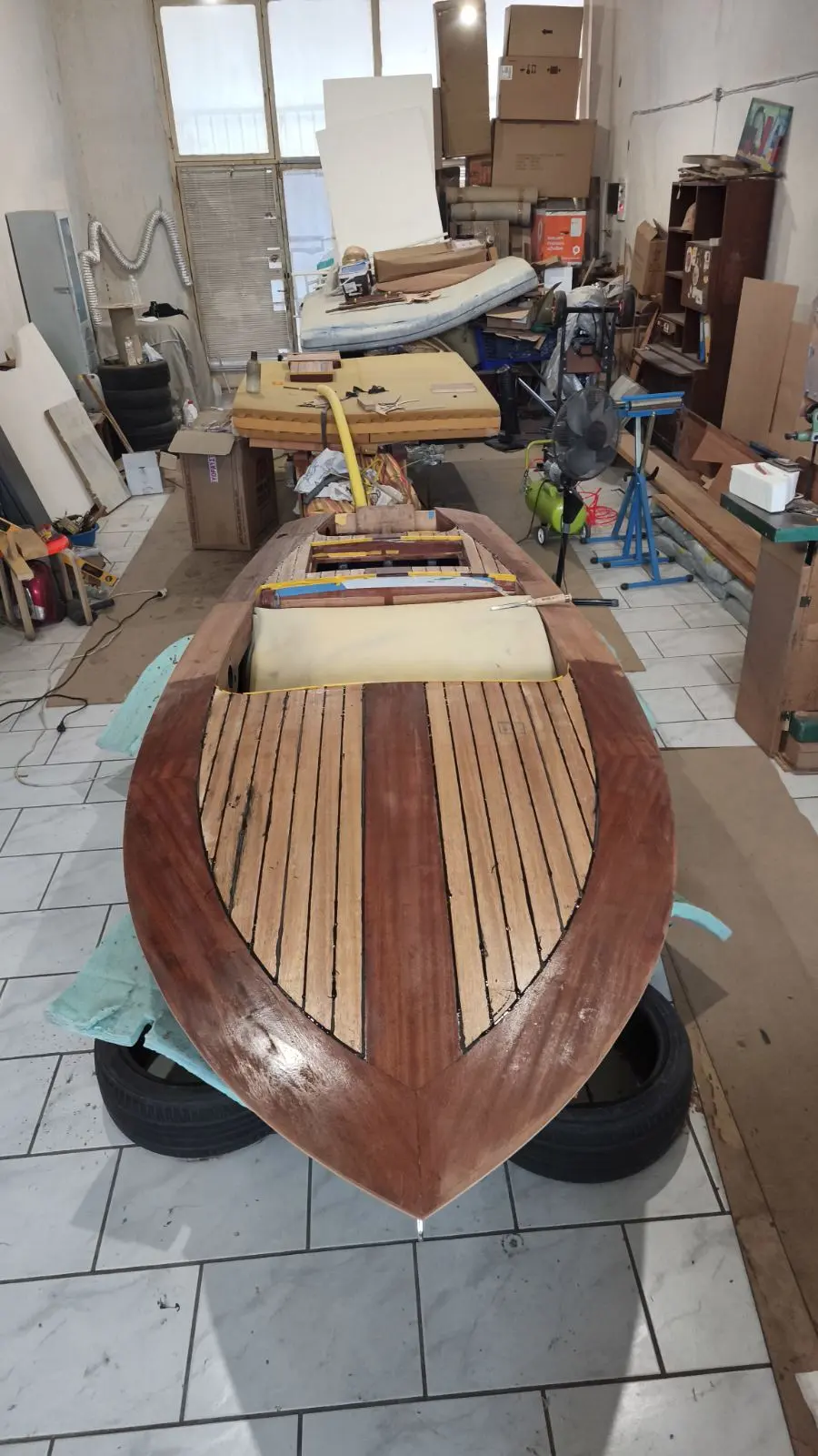
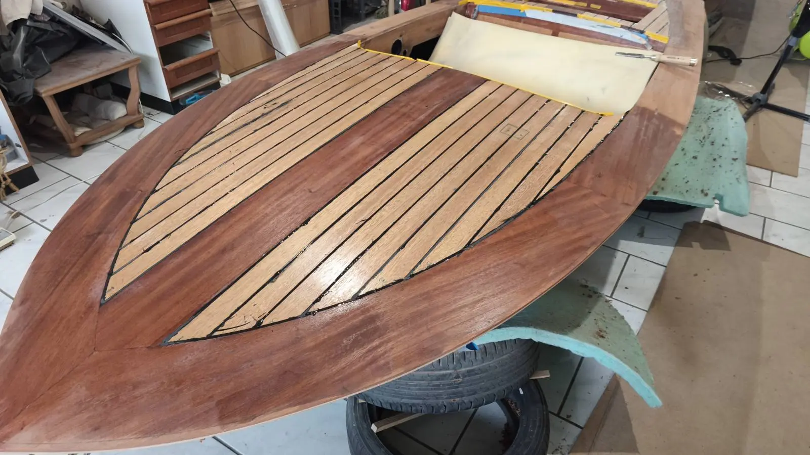
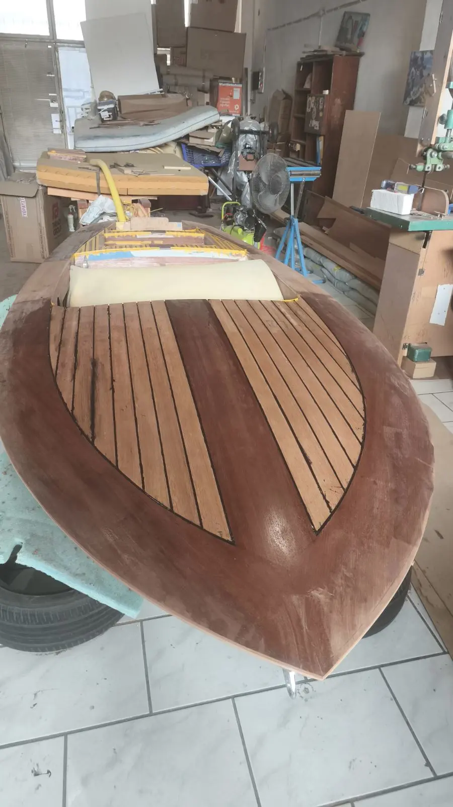
Gluing on the deck plywood

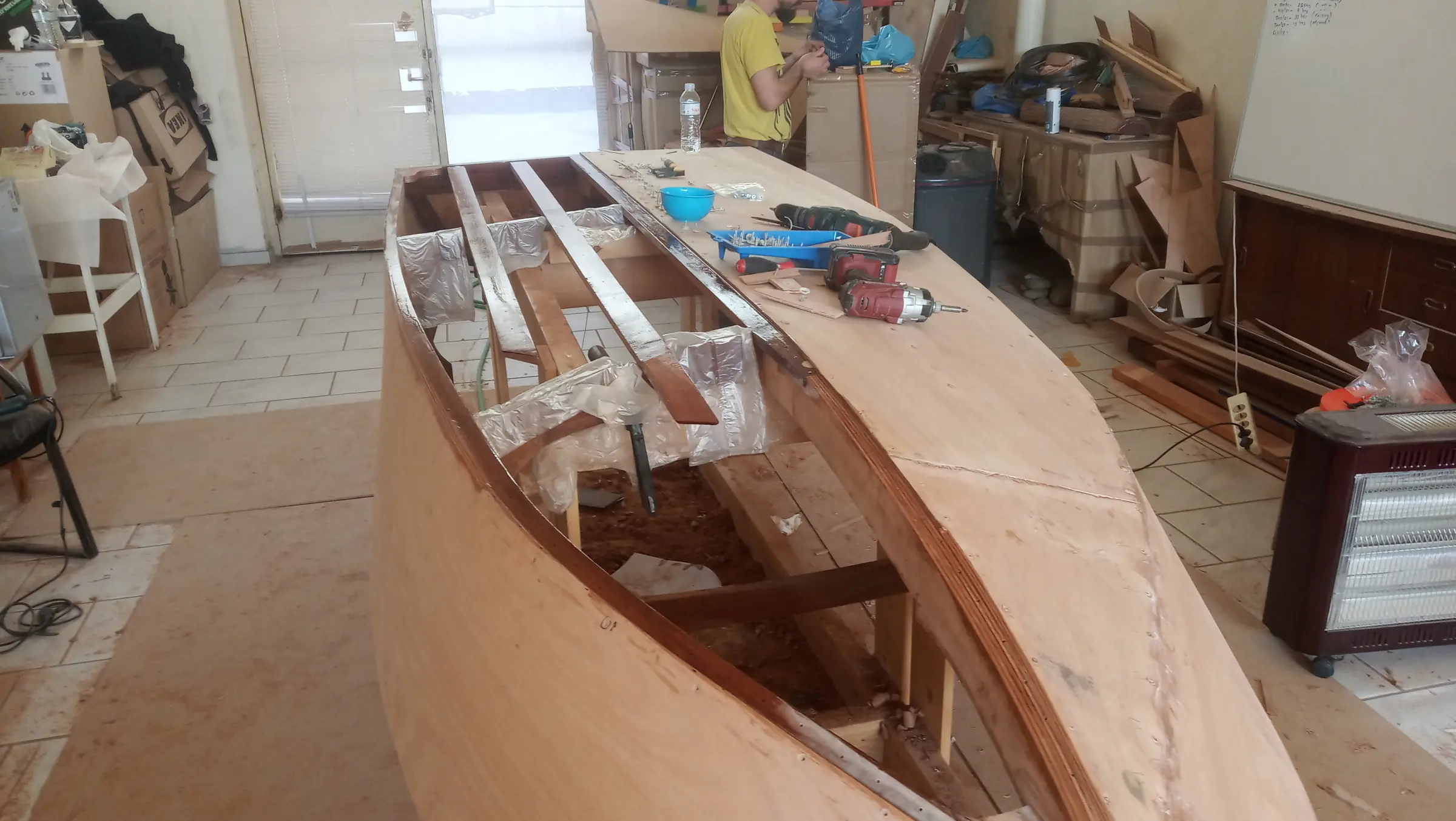
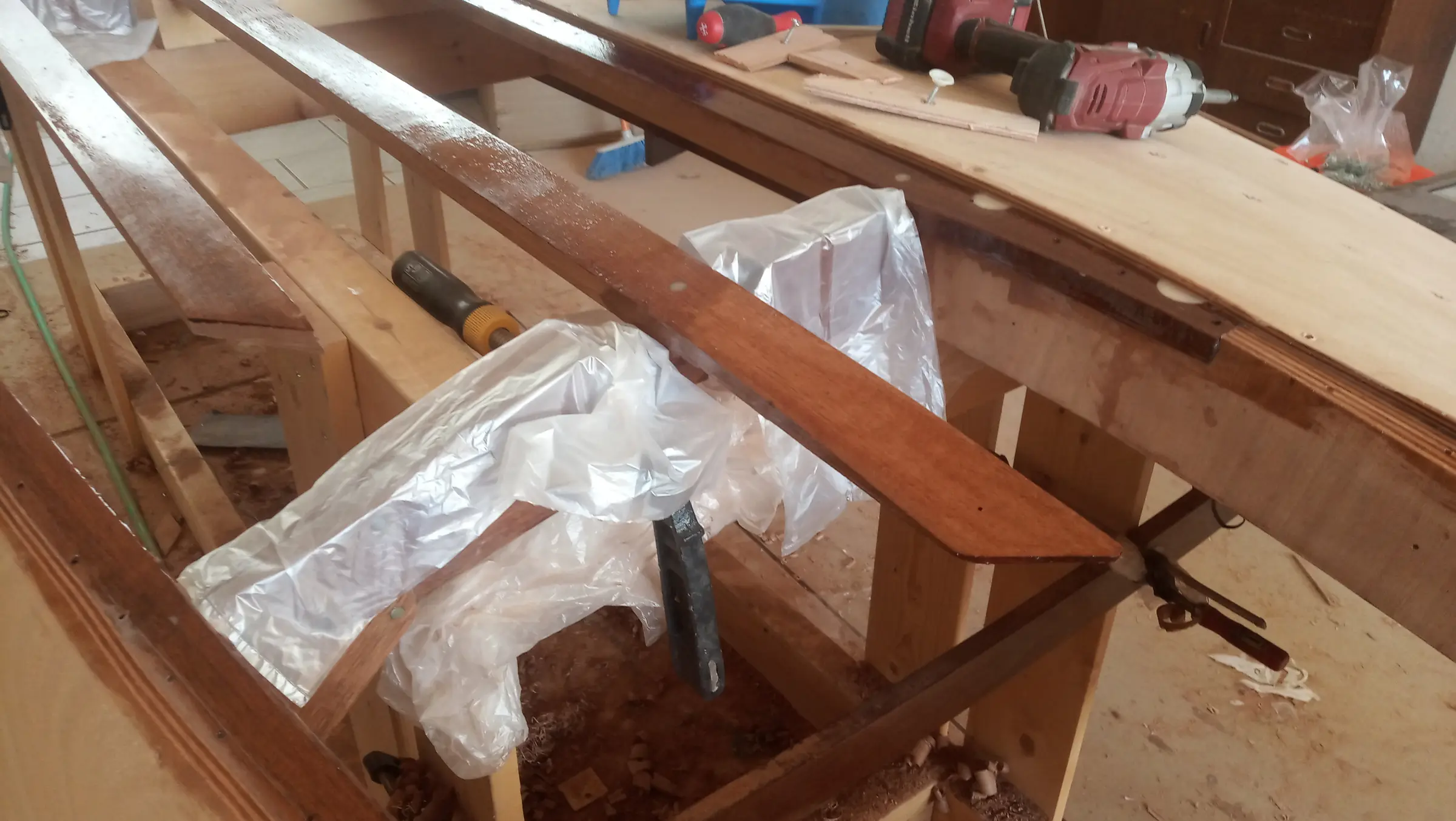
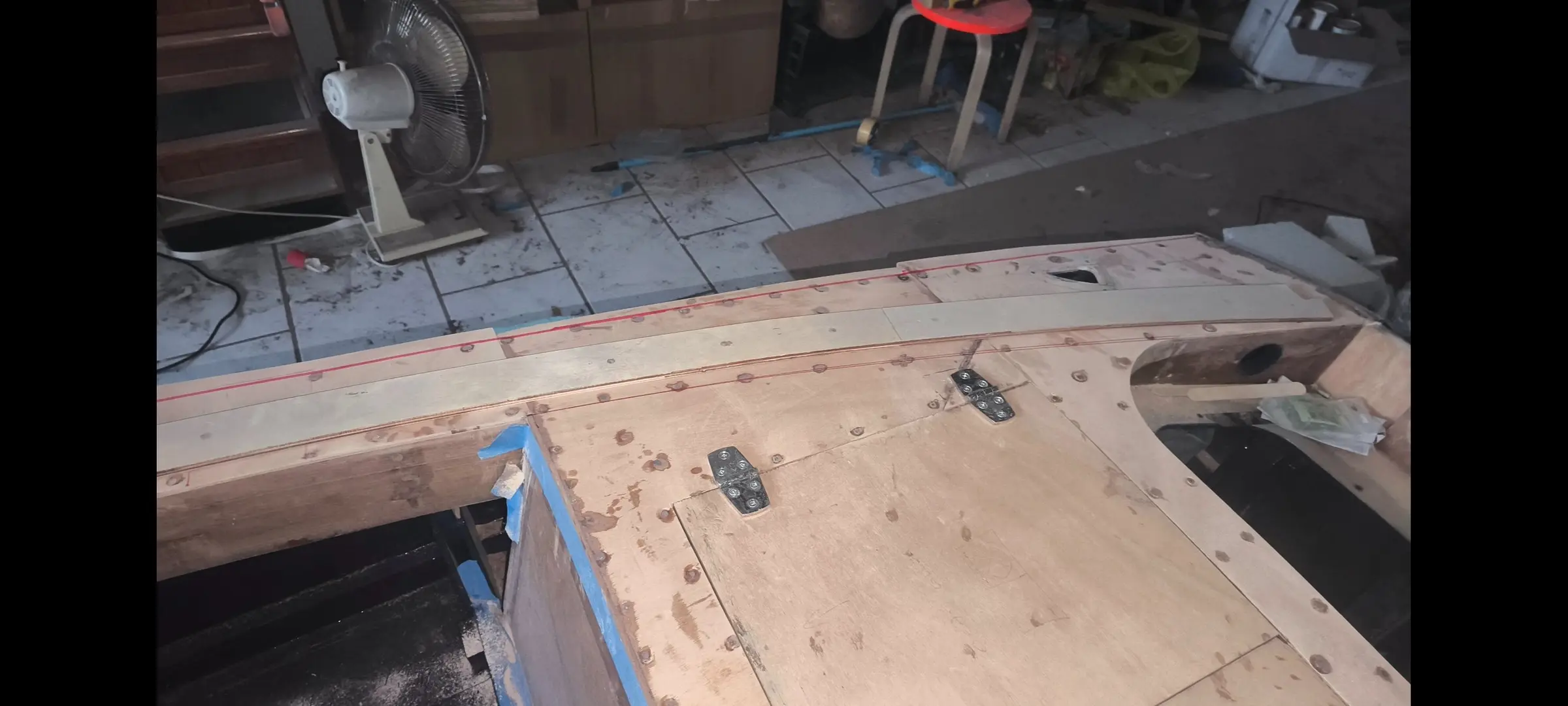
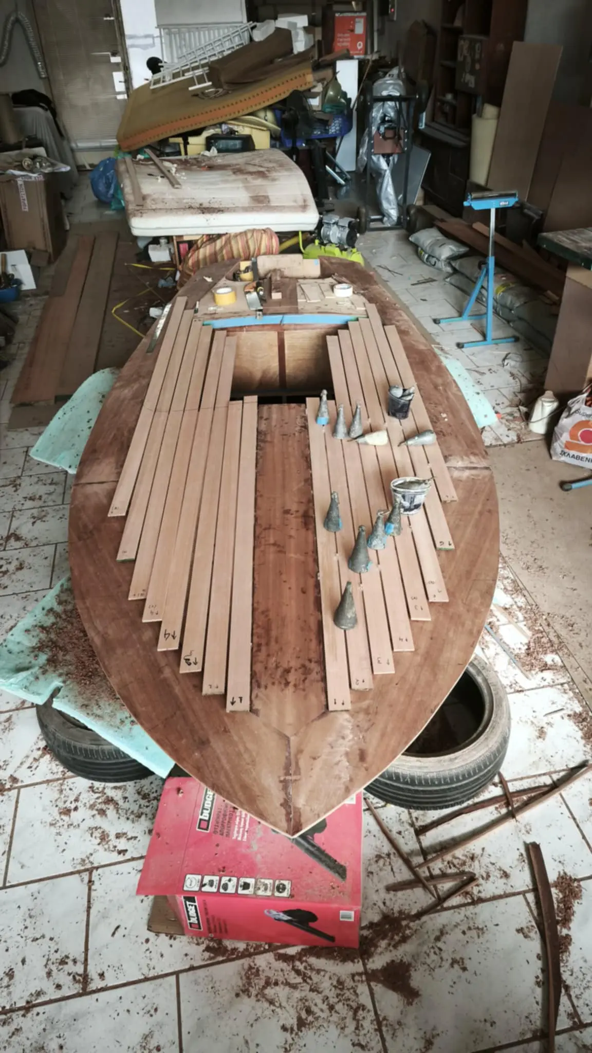
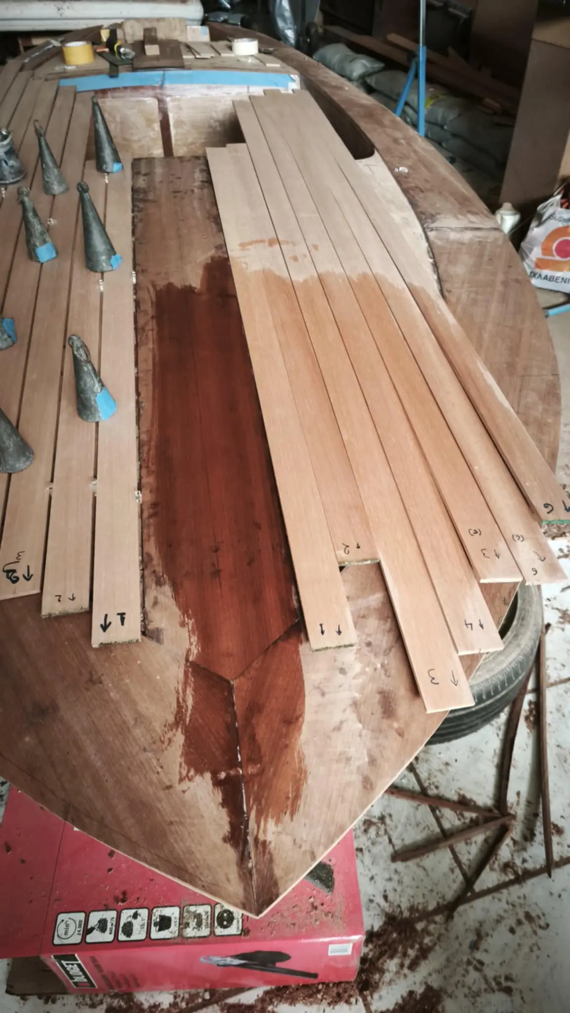
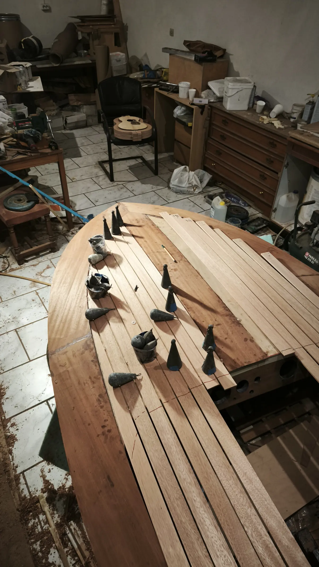
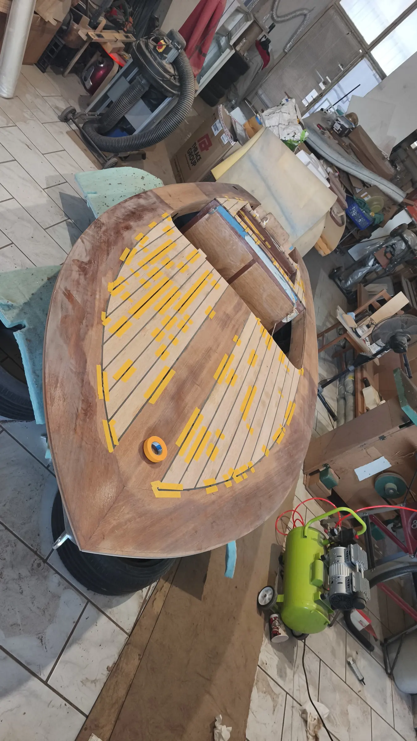
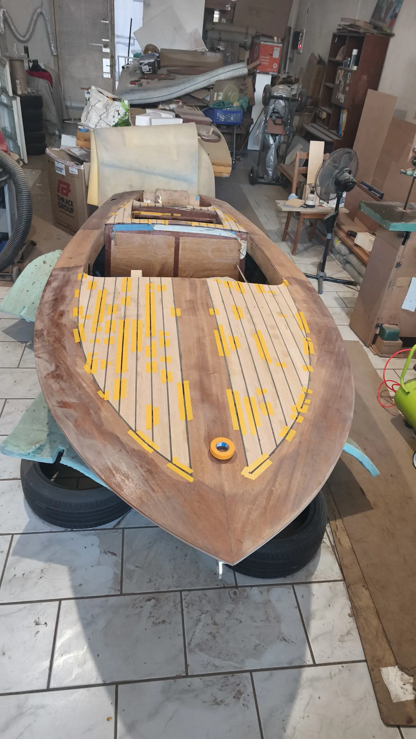
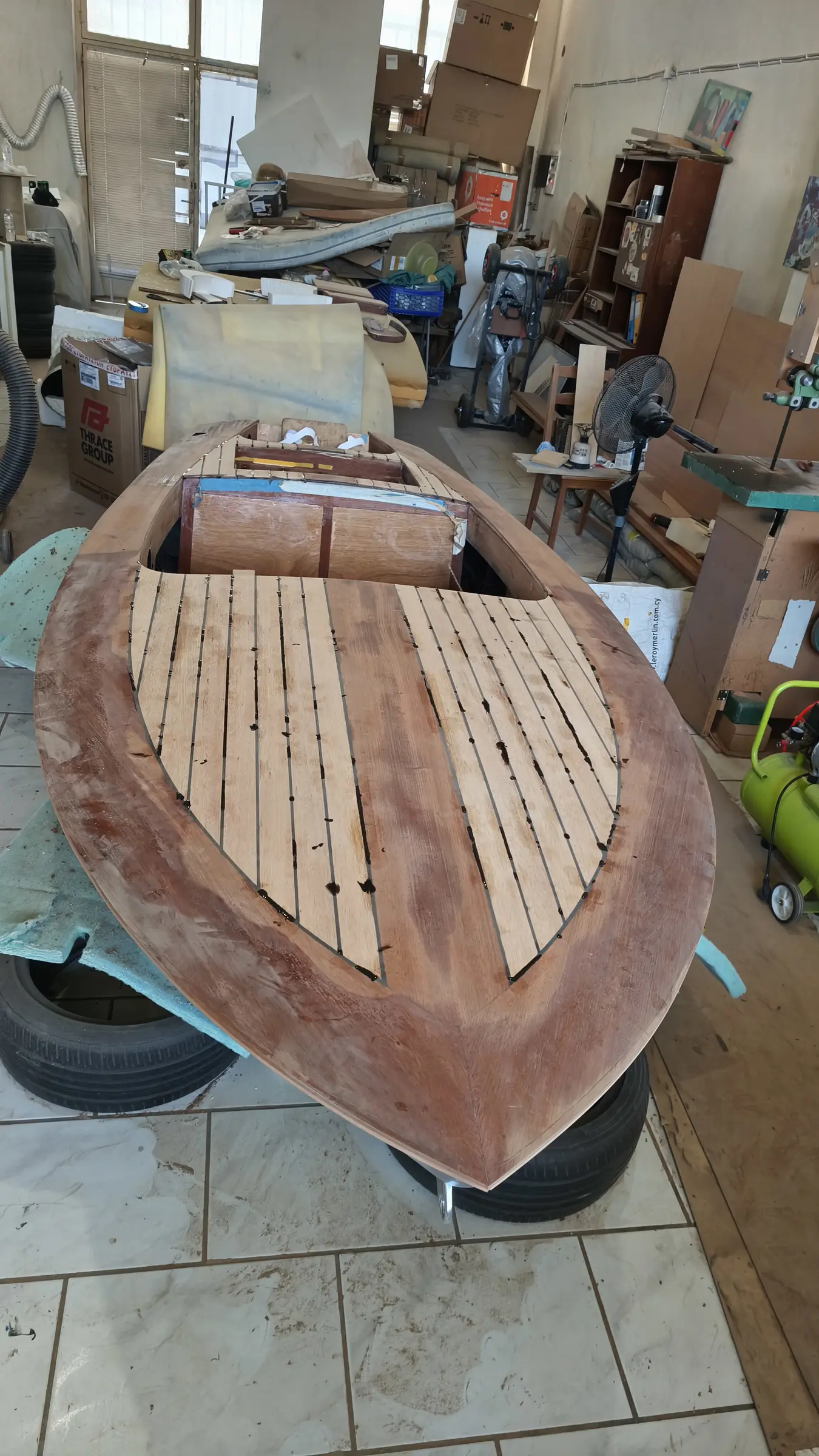
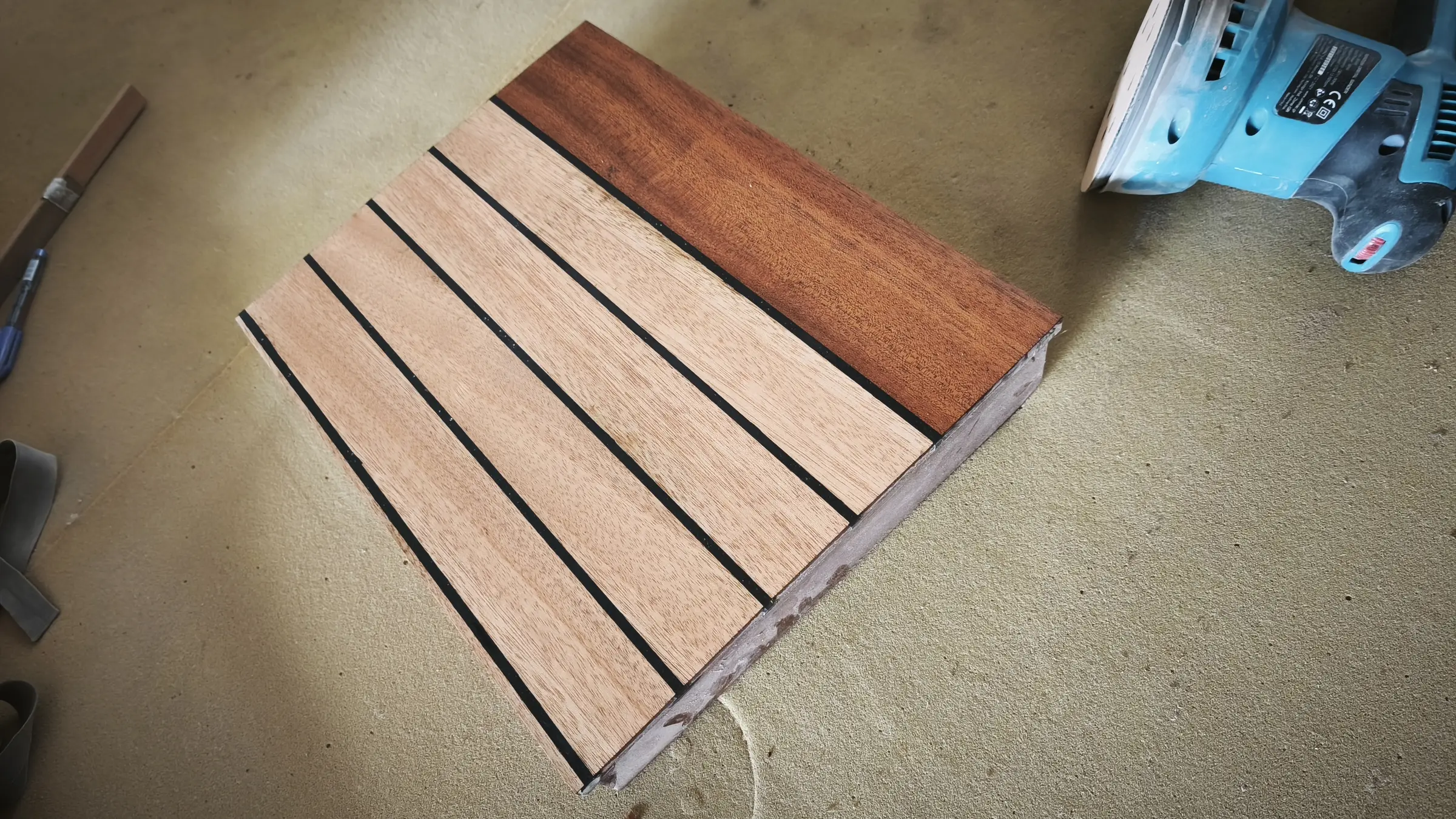
For the deck, 6 mm okoume plywood will be glued on, with solid sipo on top around the outside and American mahogany on the inside.
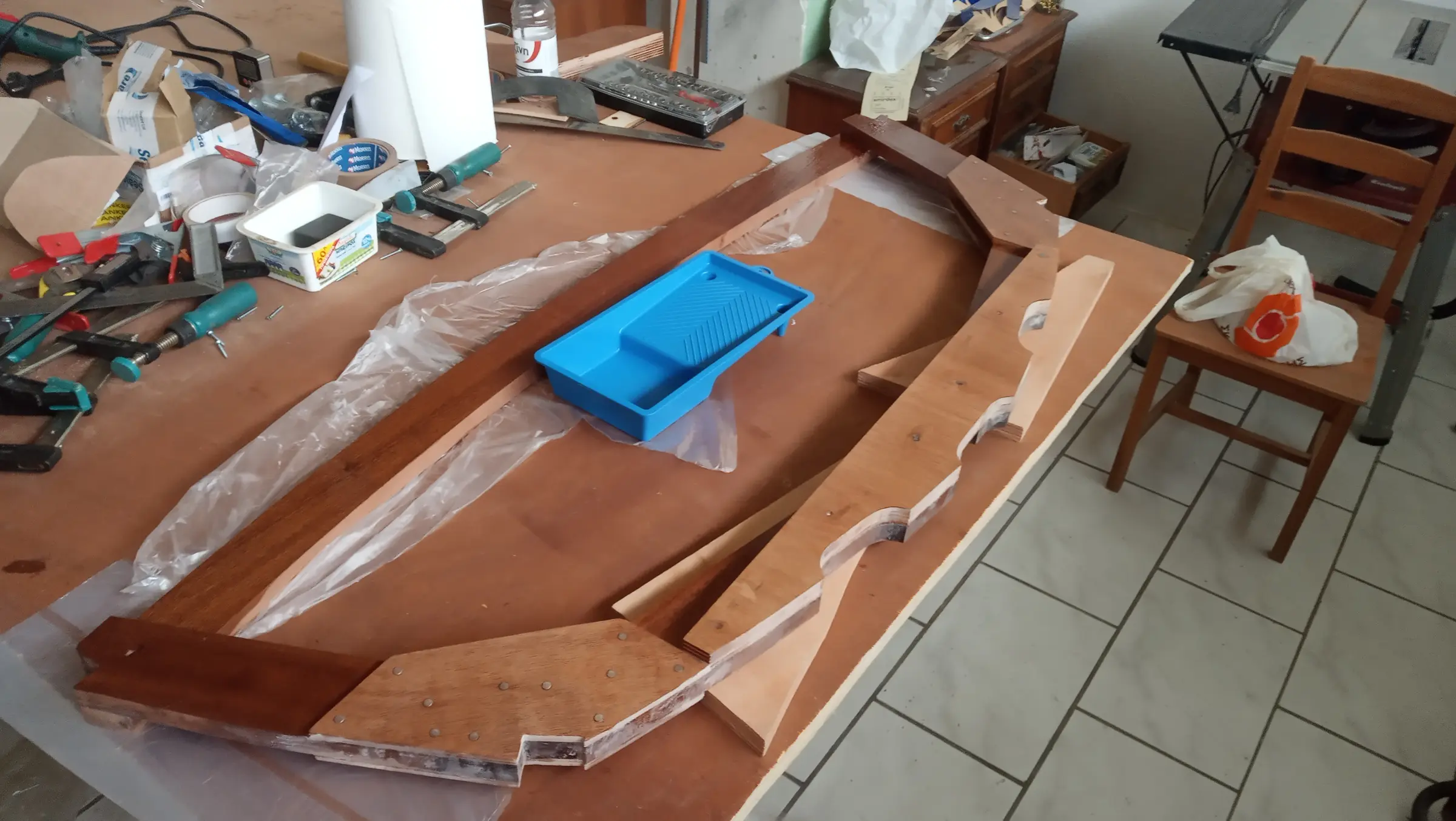
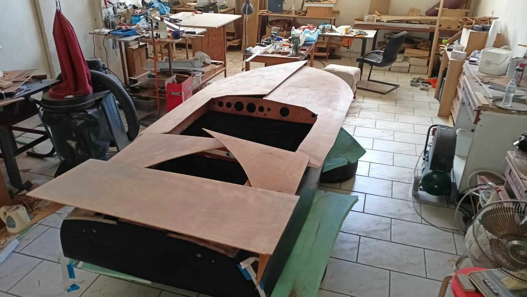
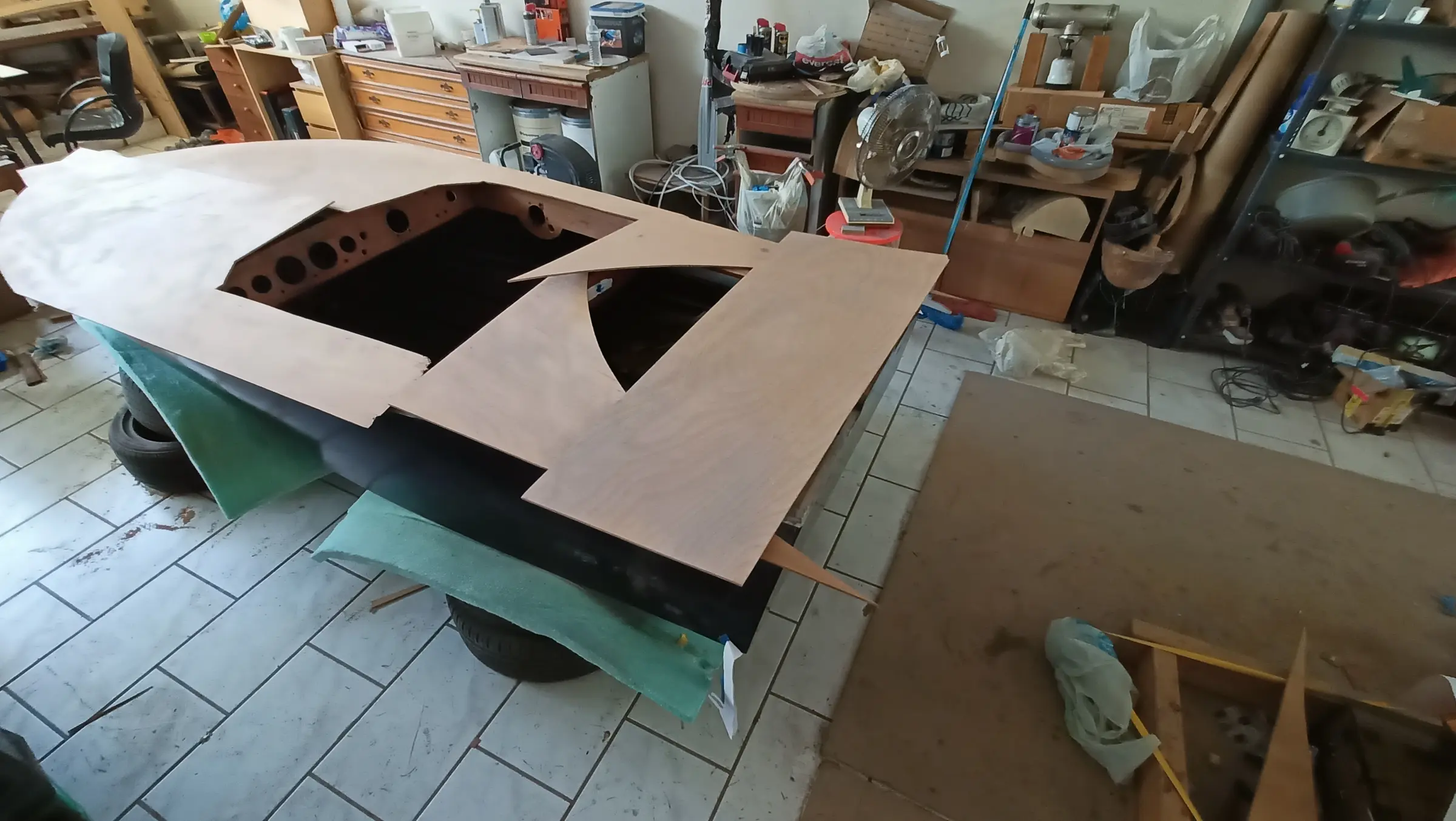
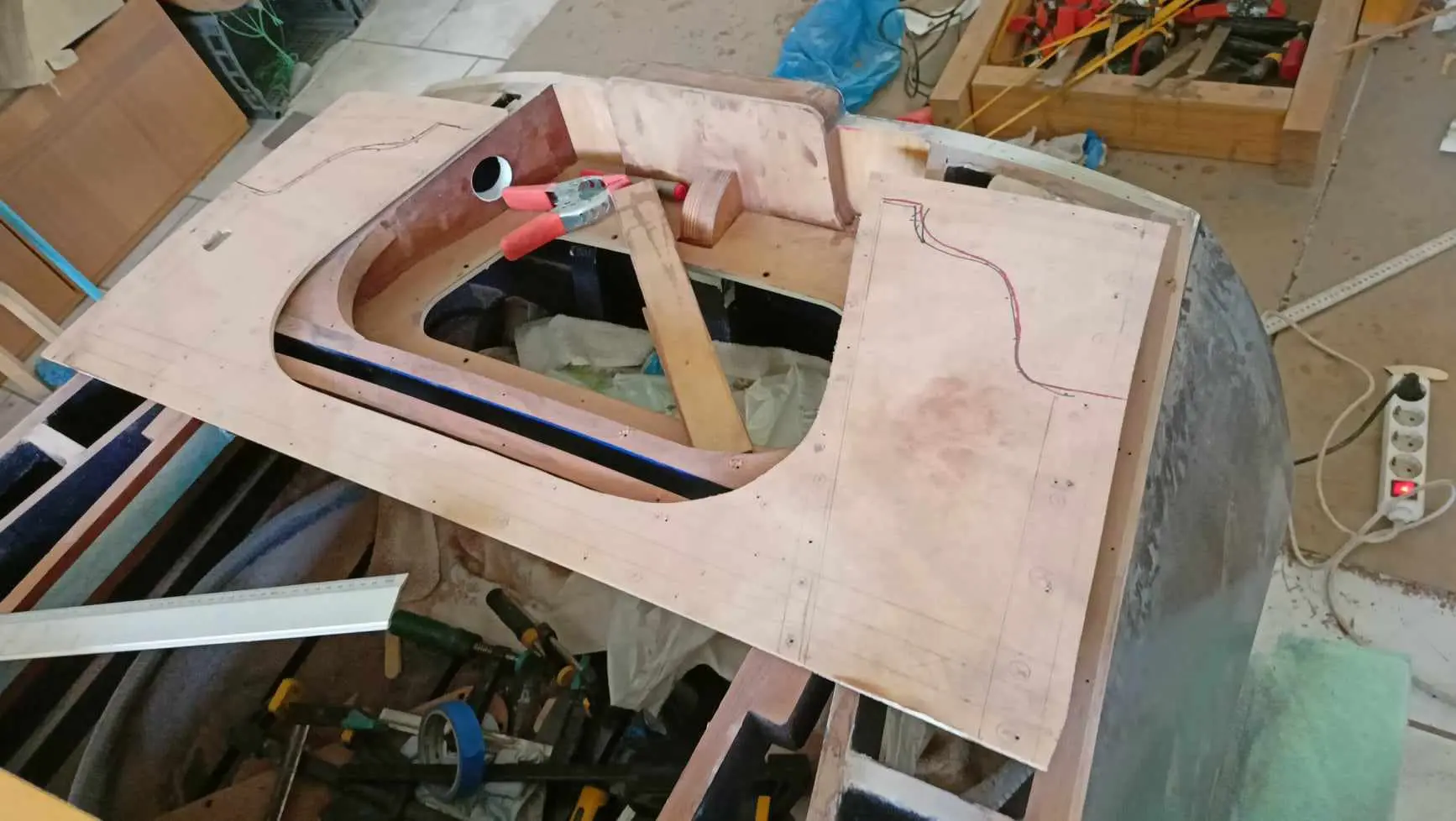
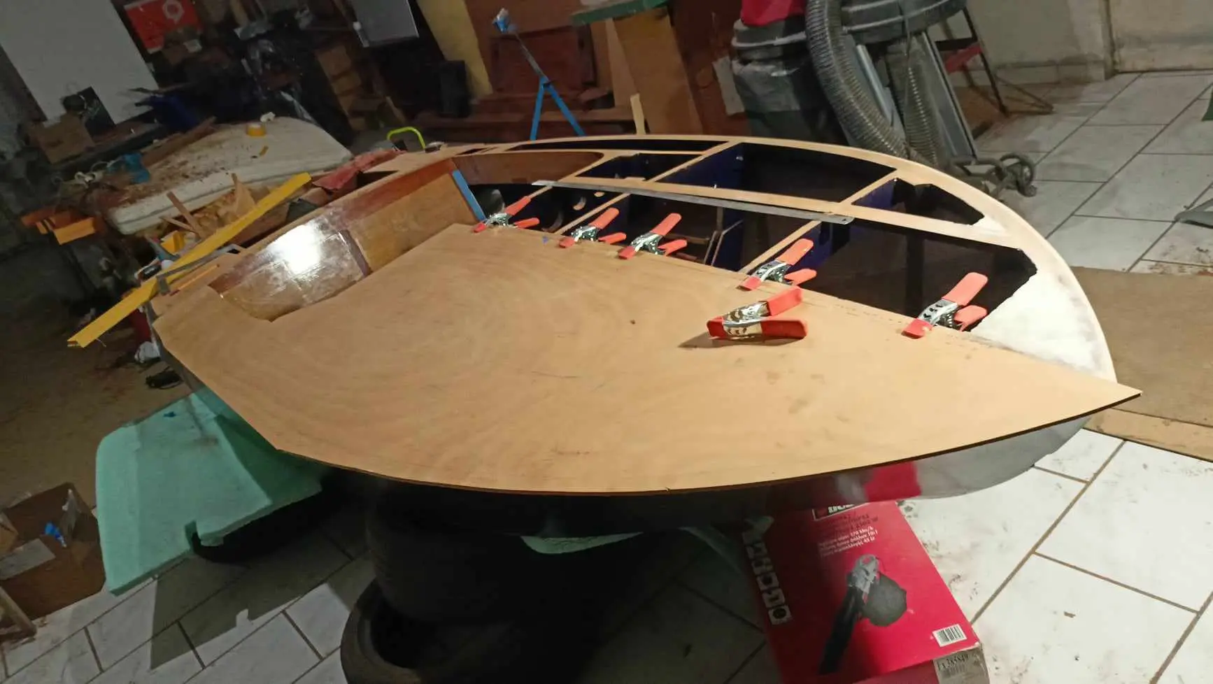
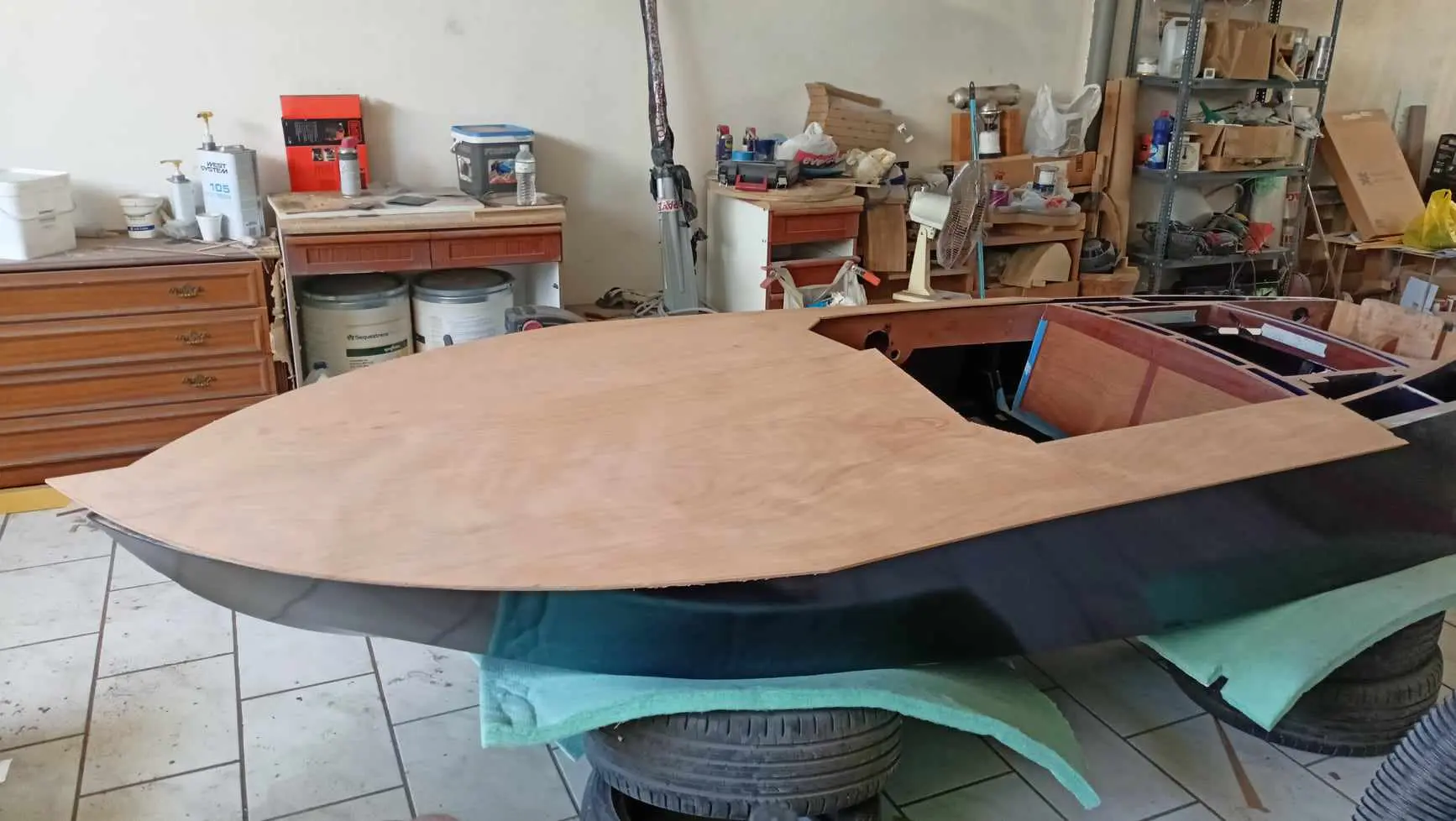
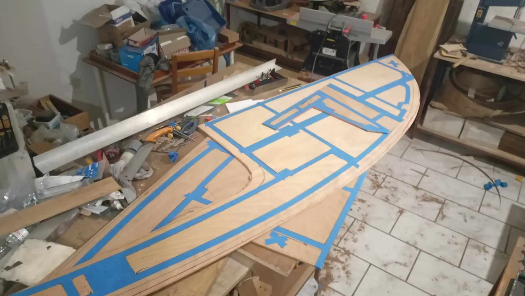
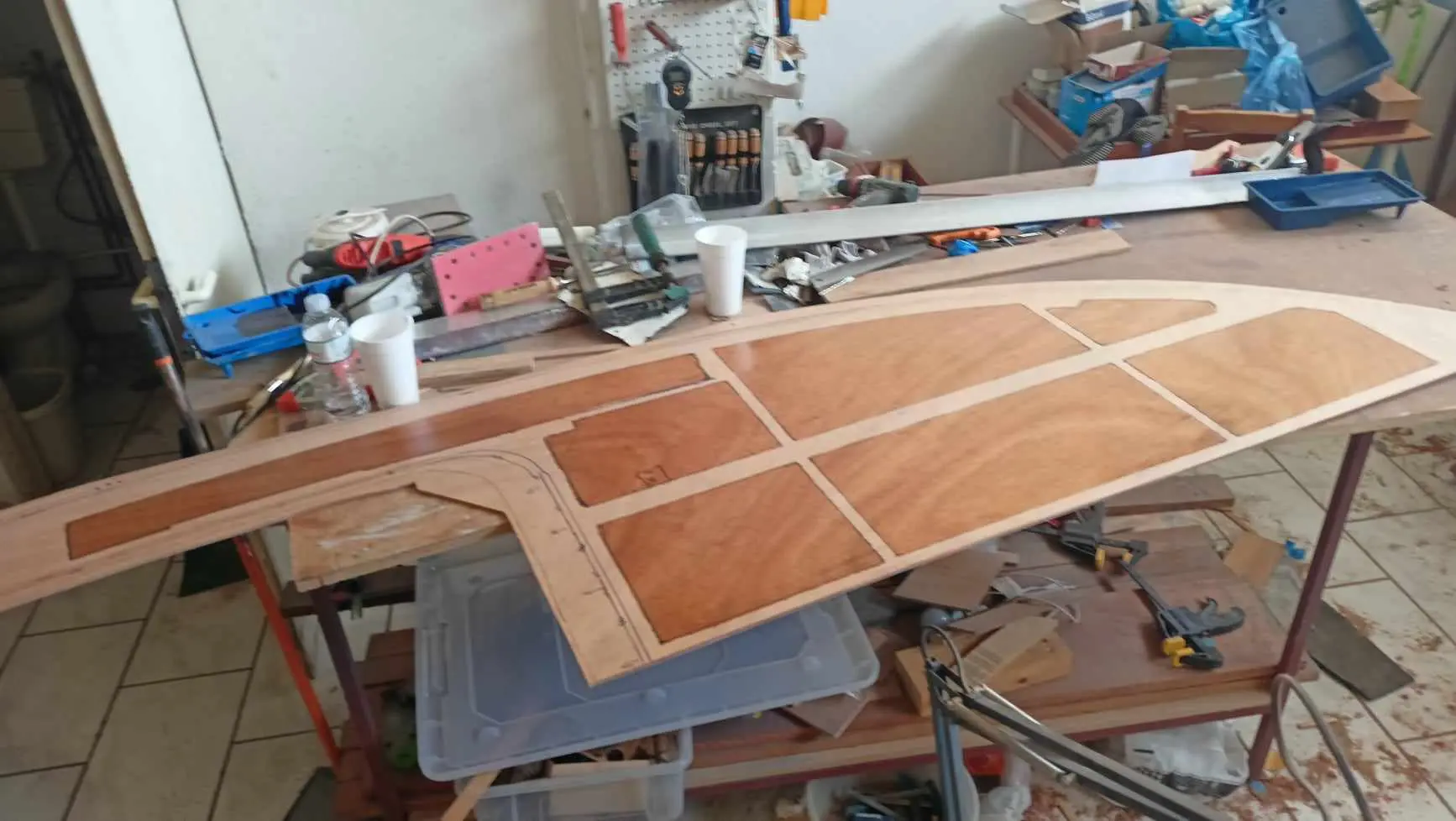
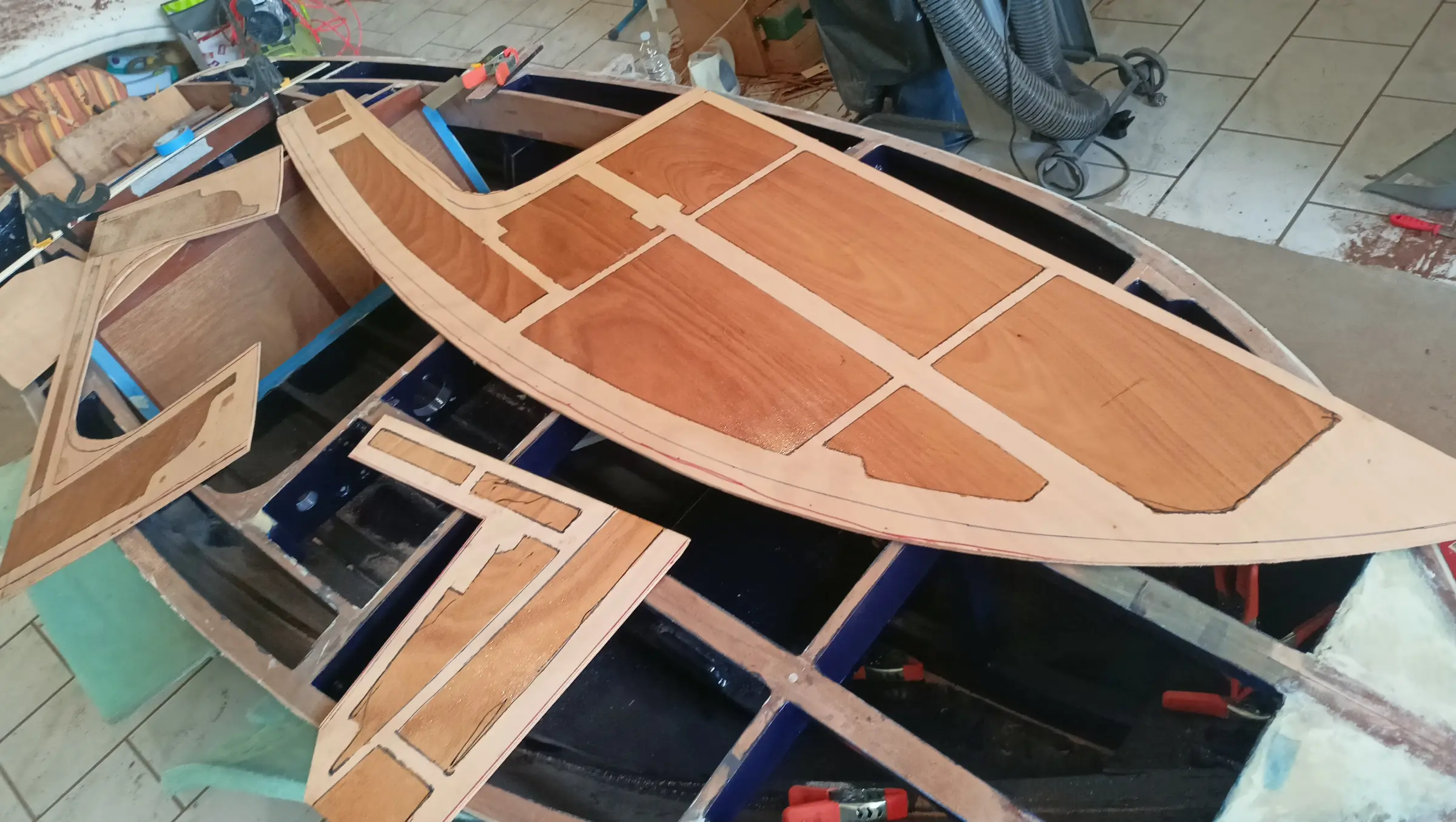
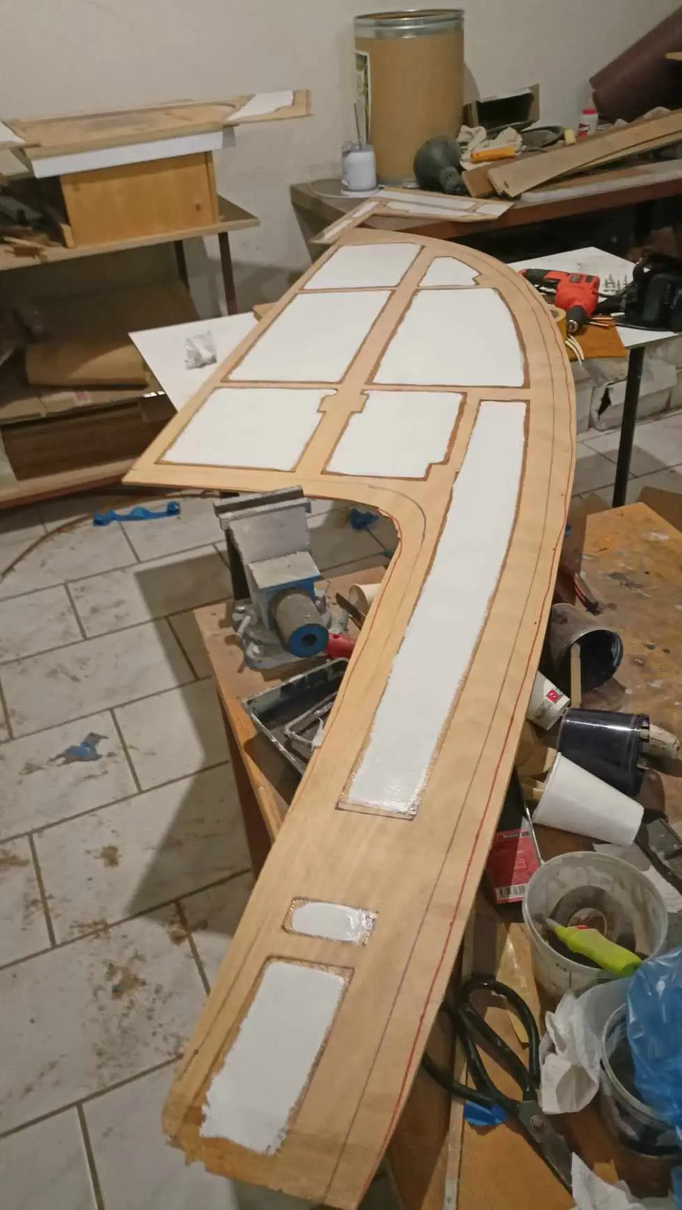
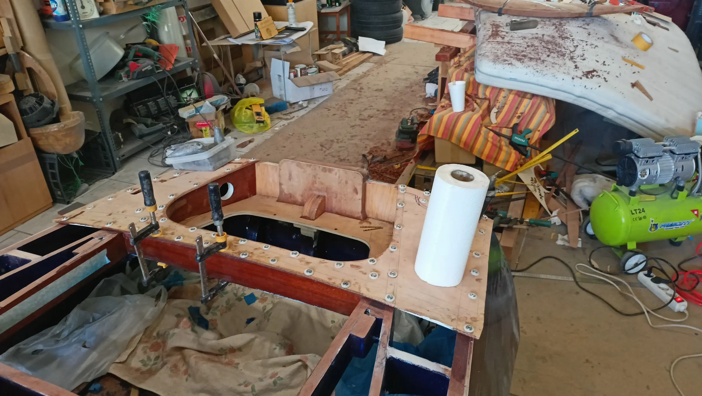
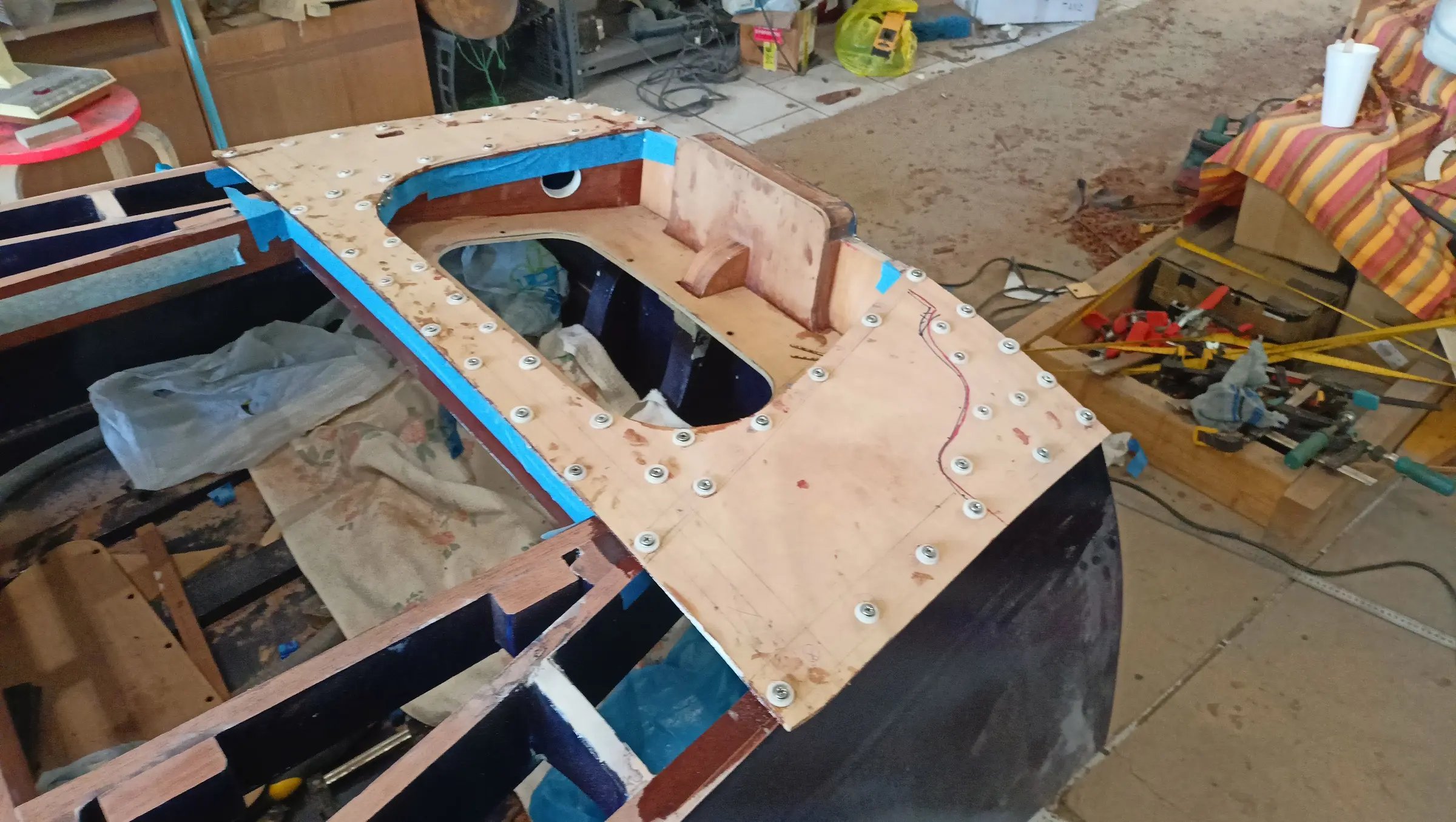
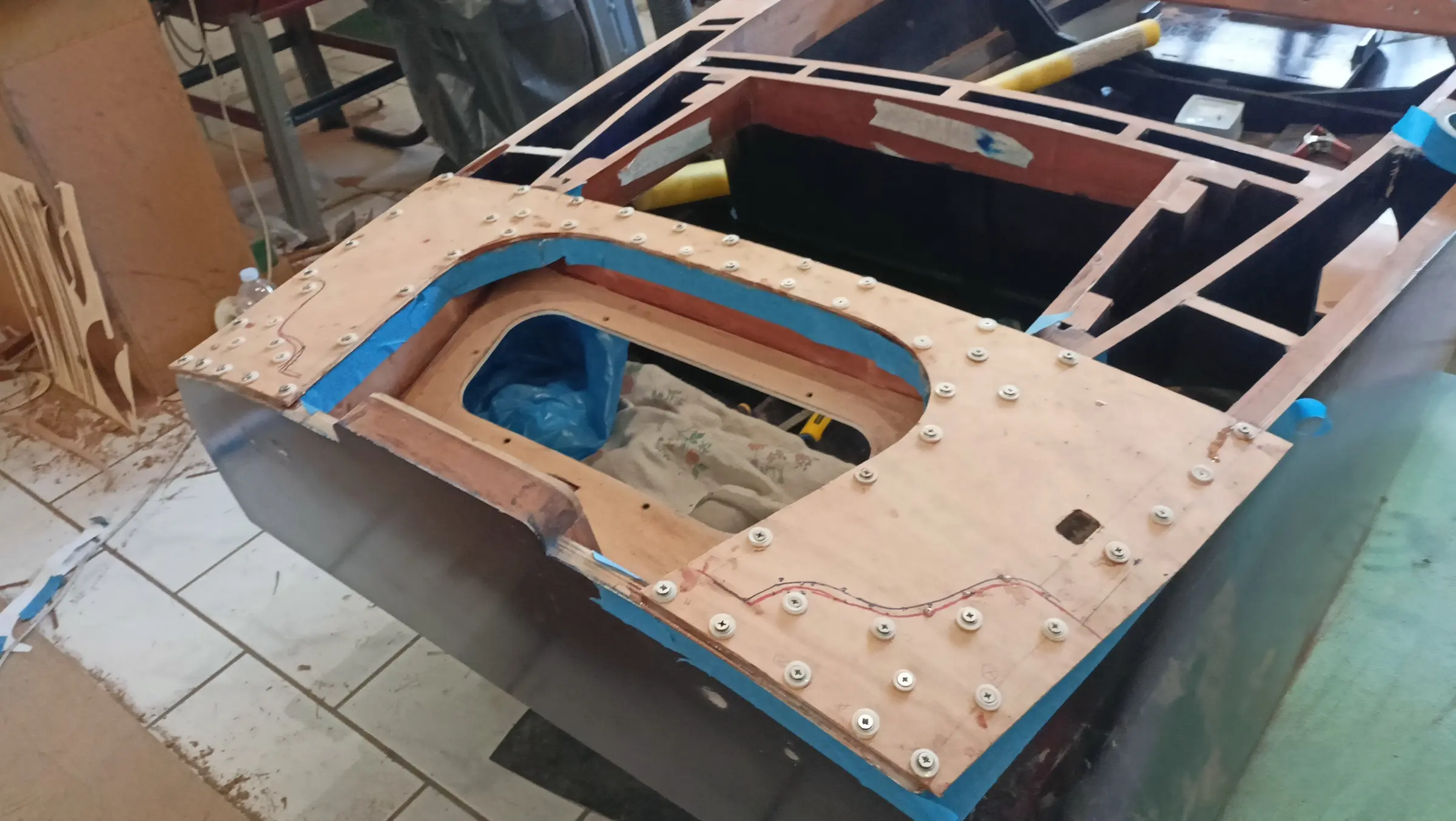
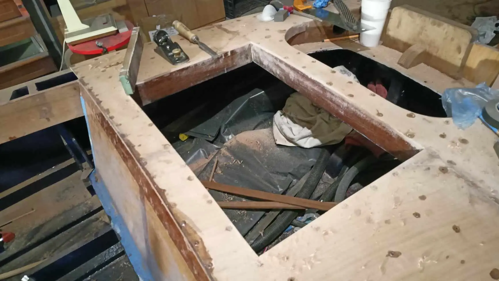
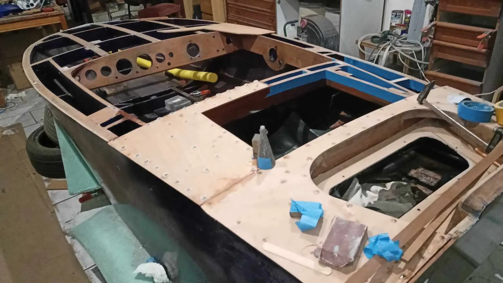
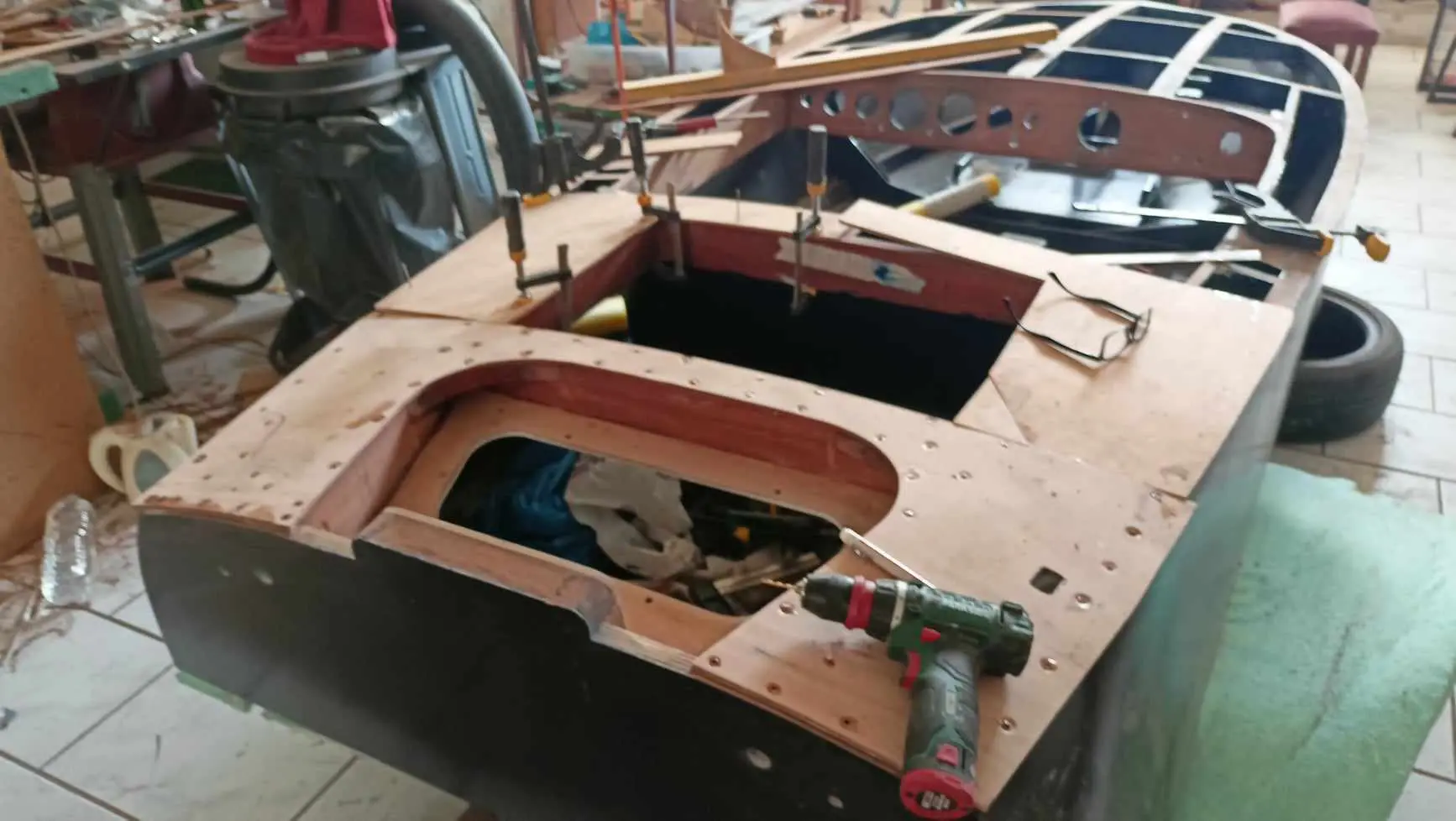
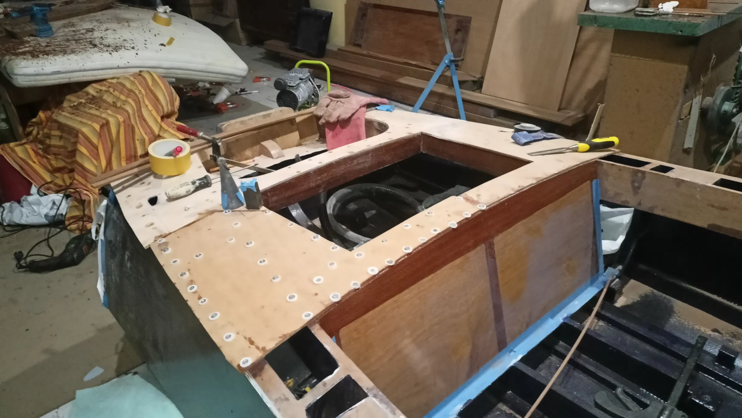
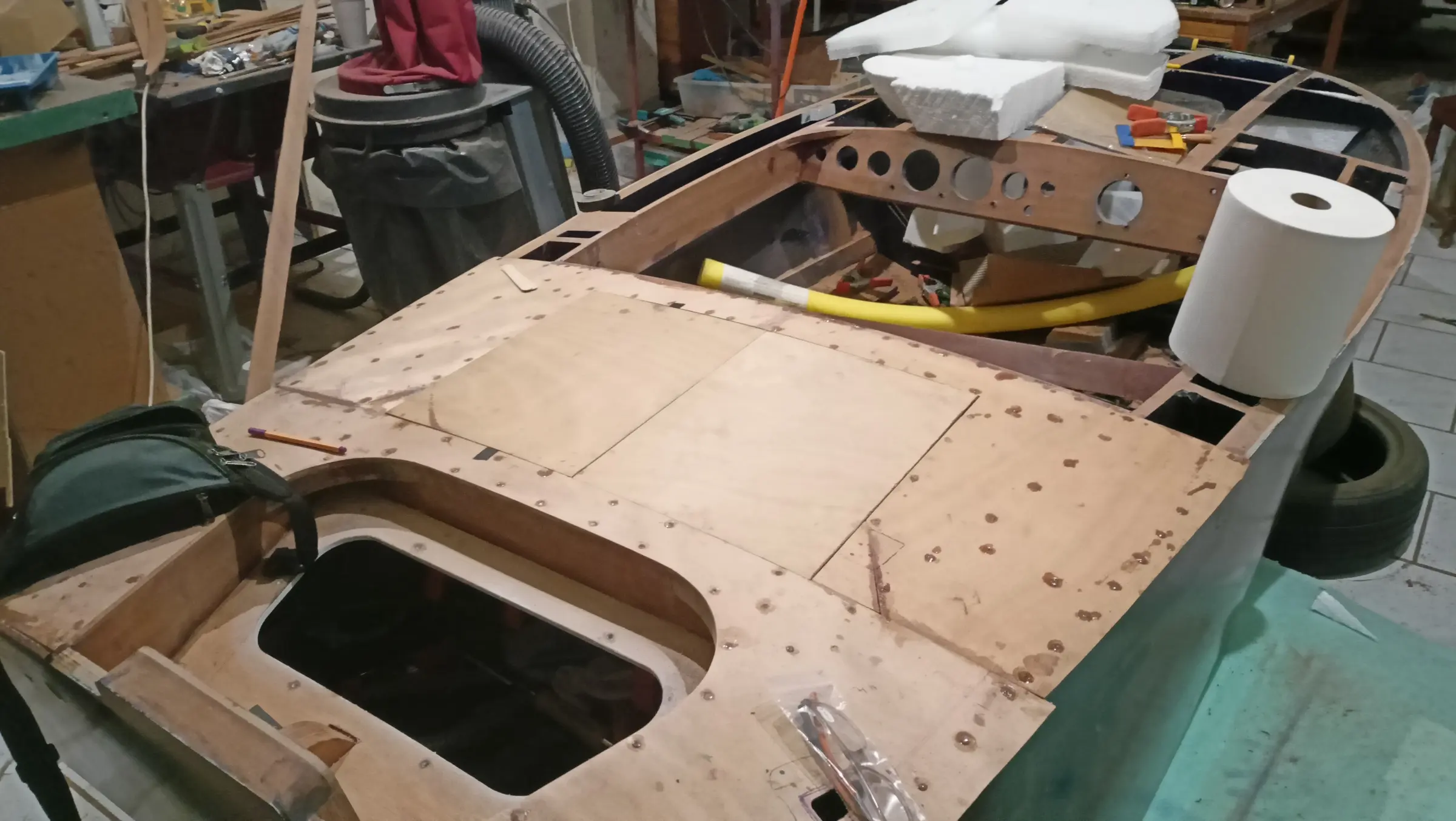
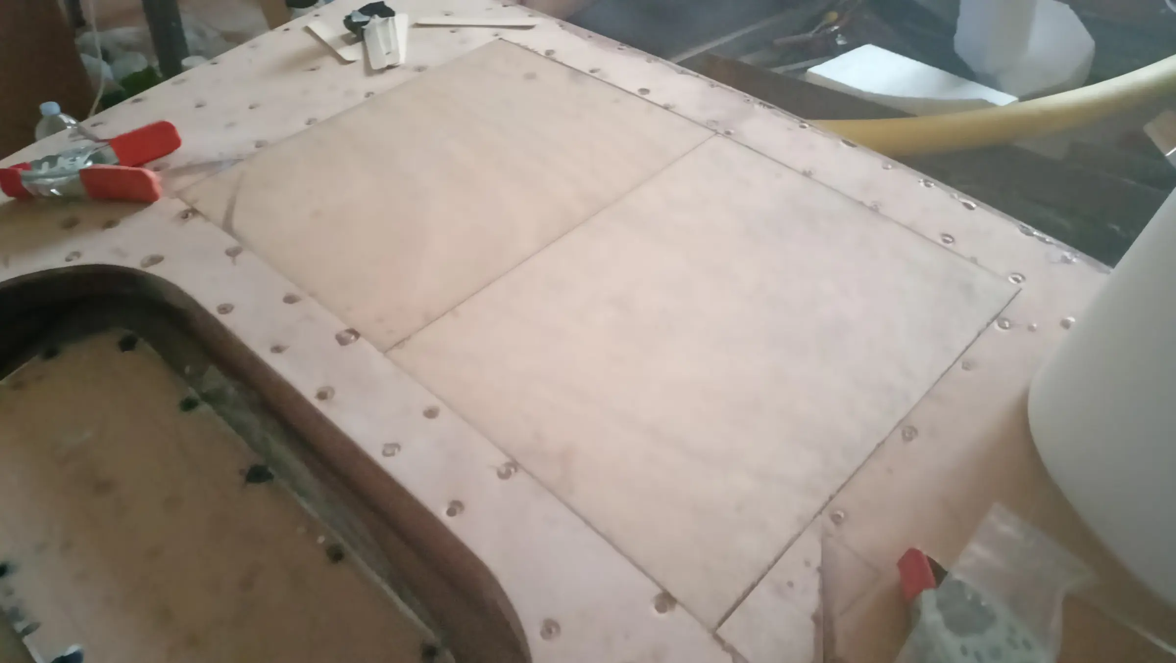
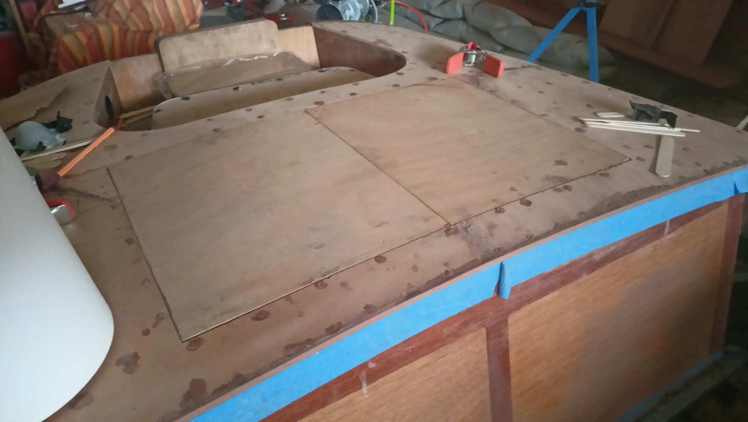
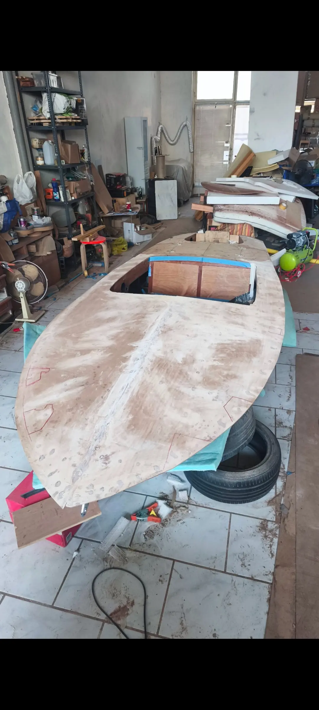
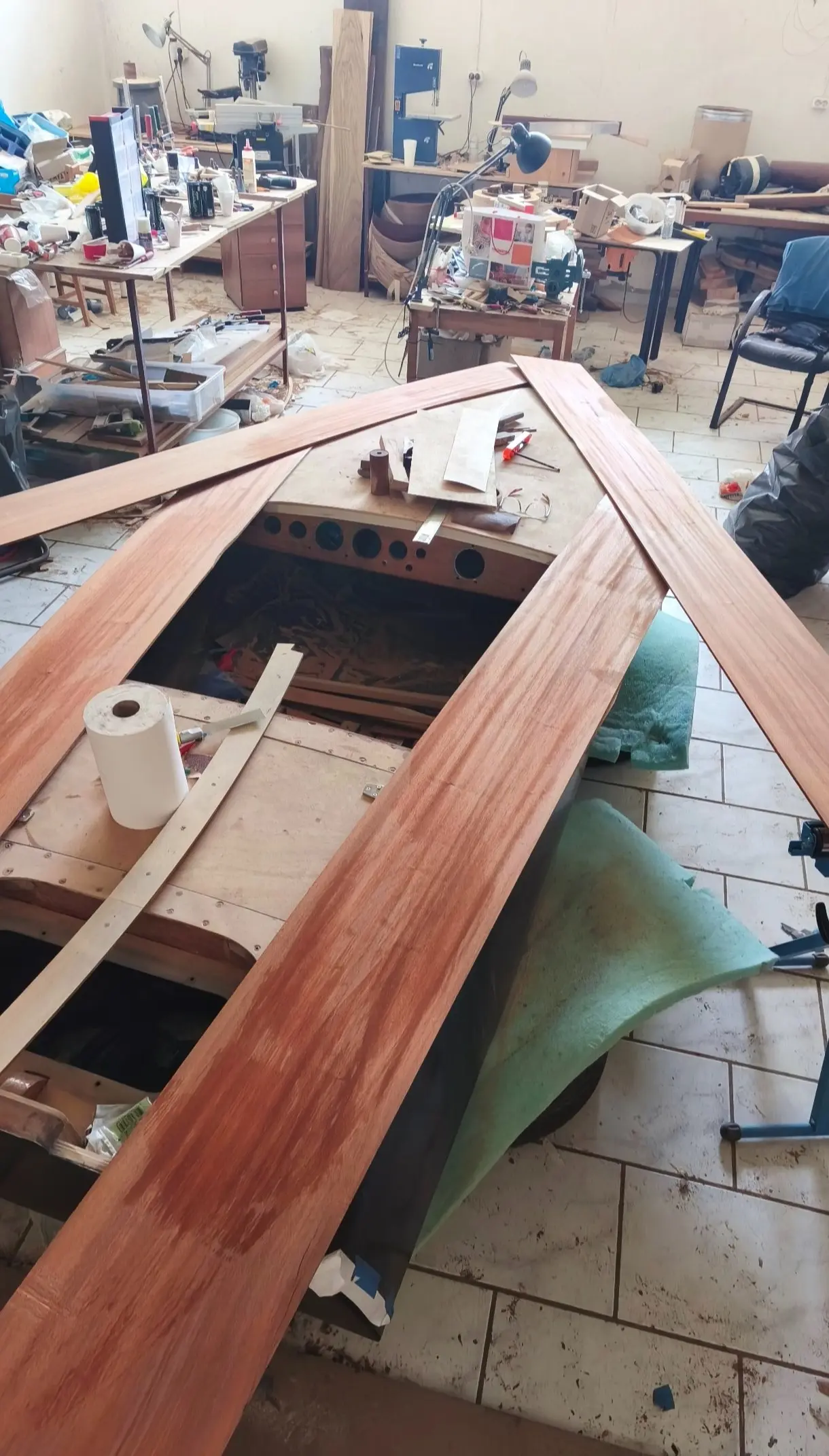
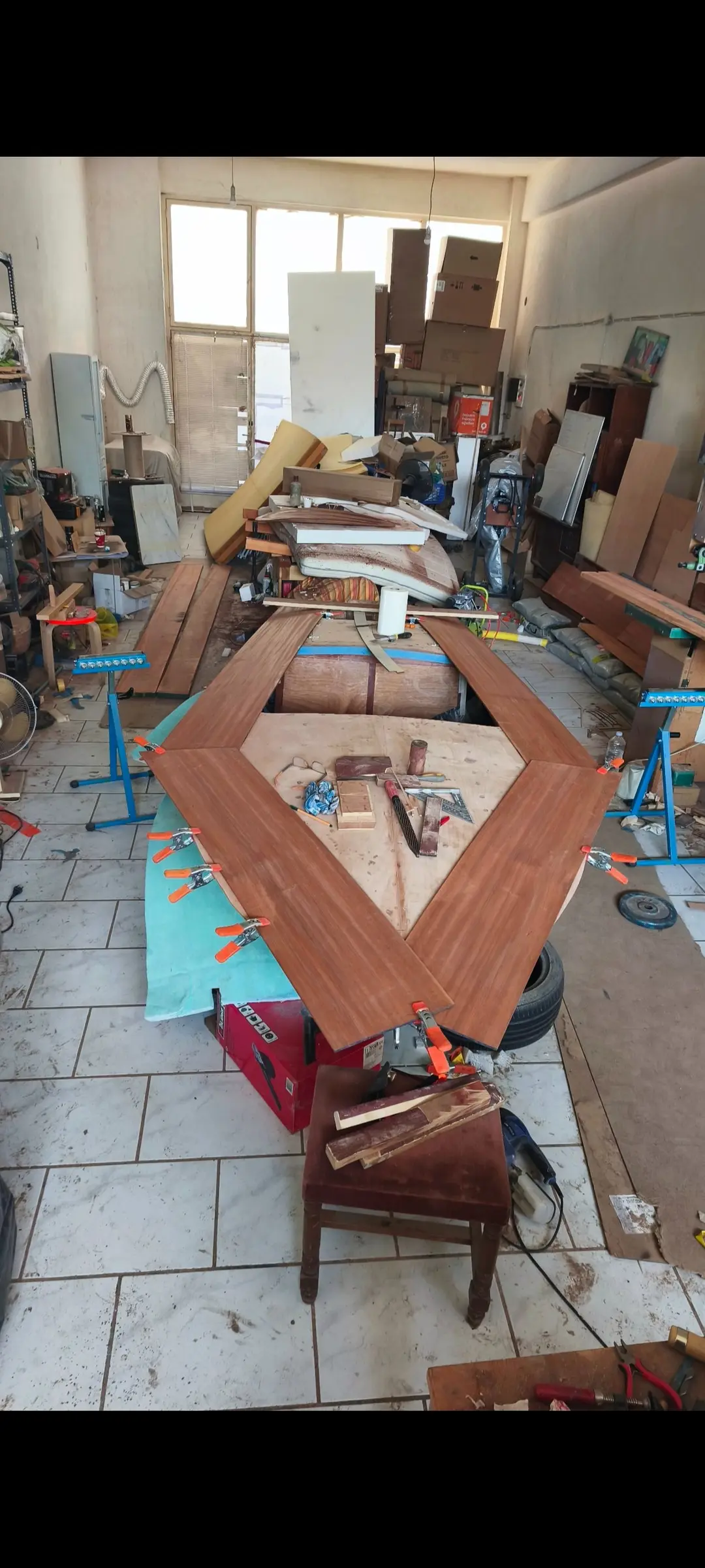
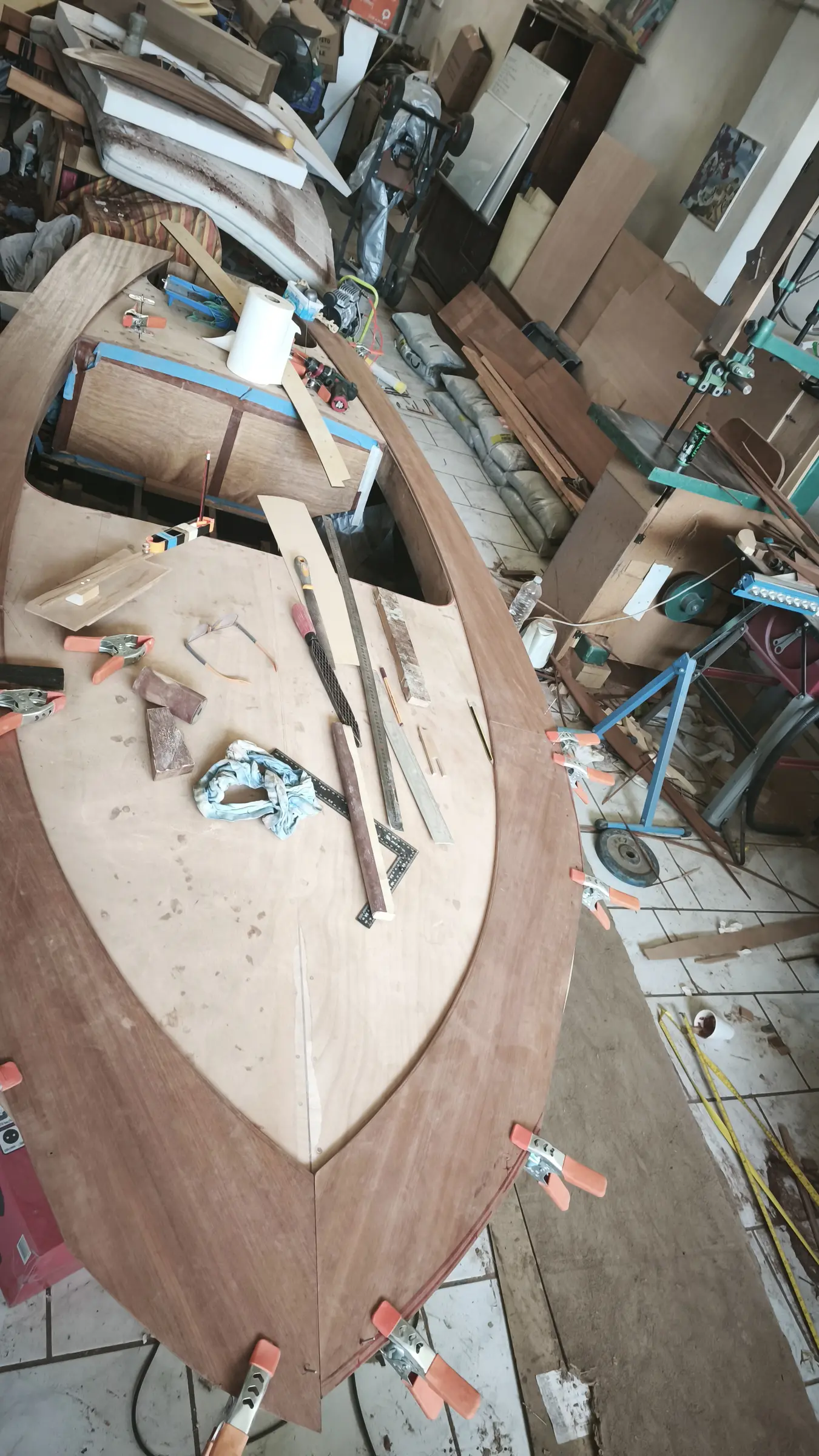
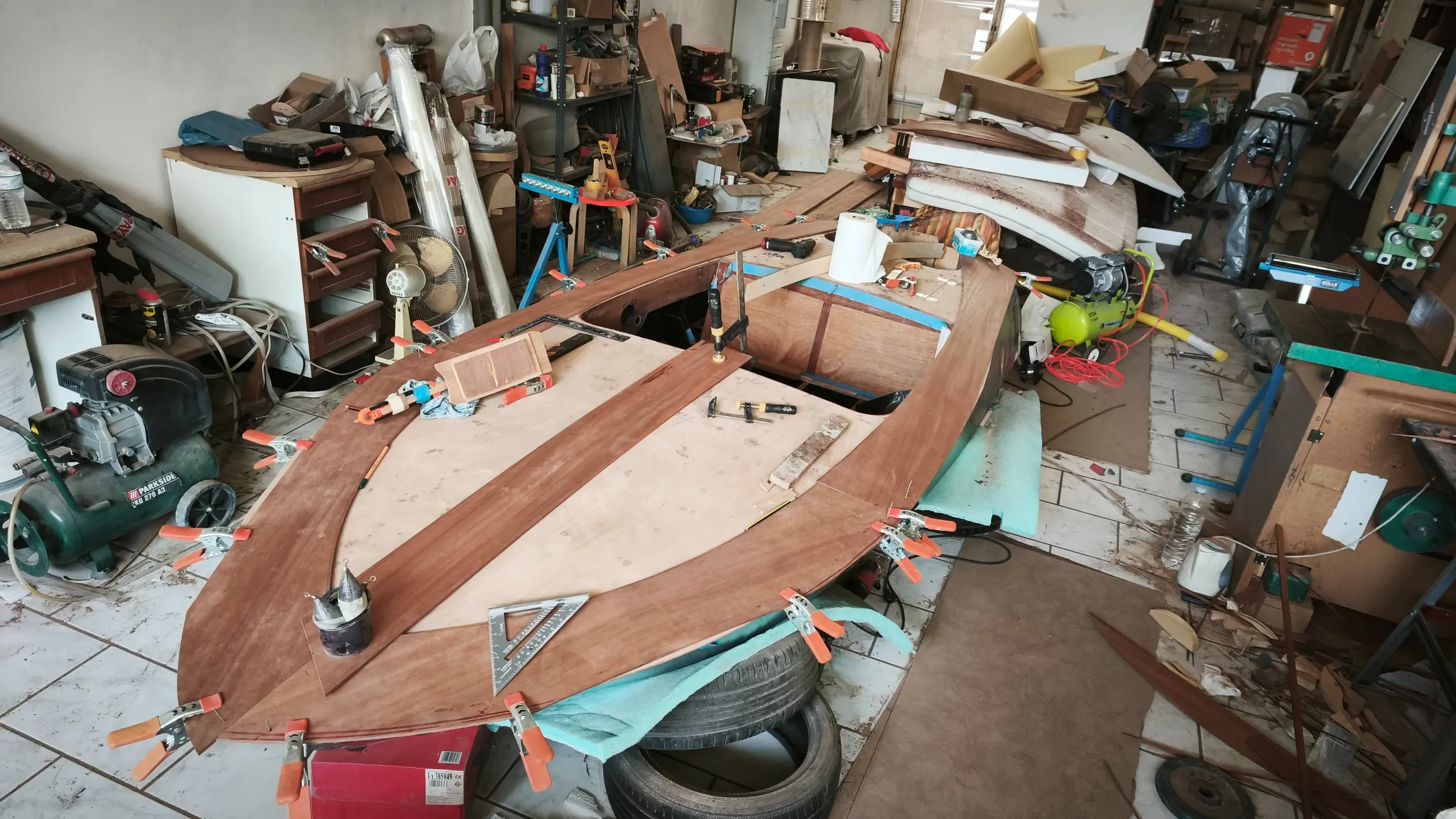
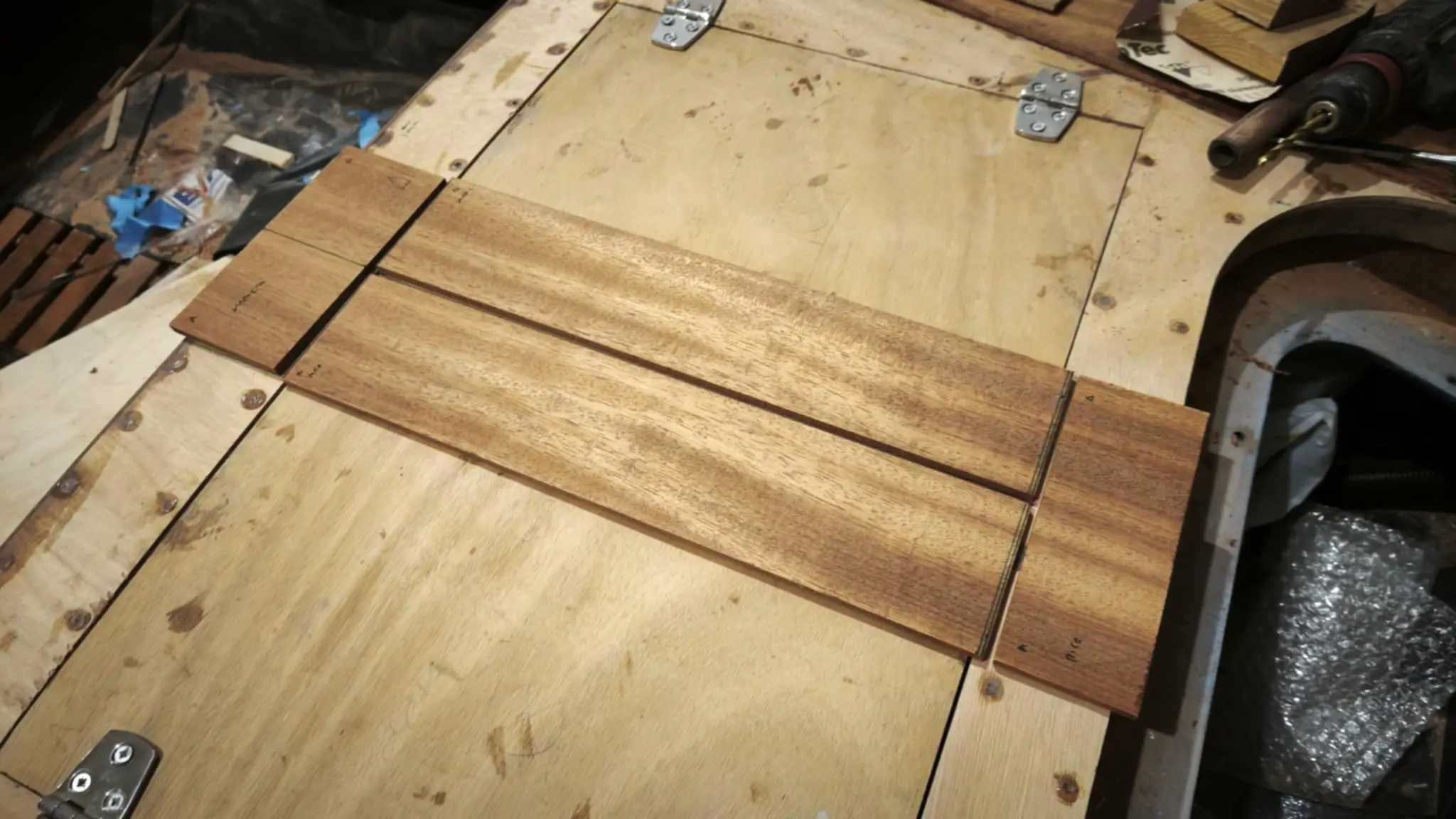
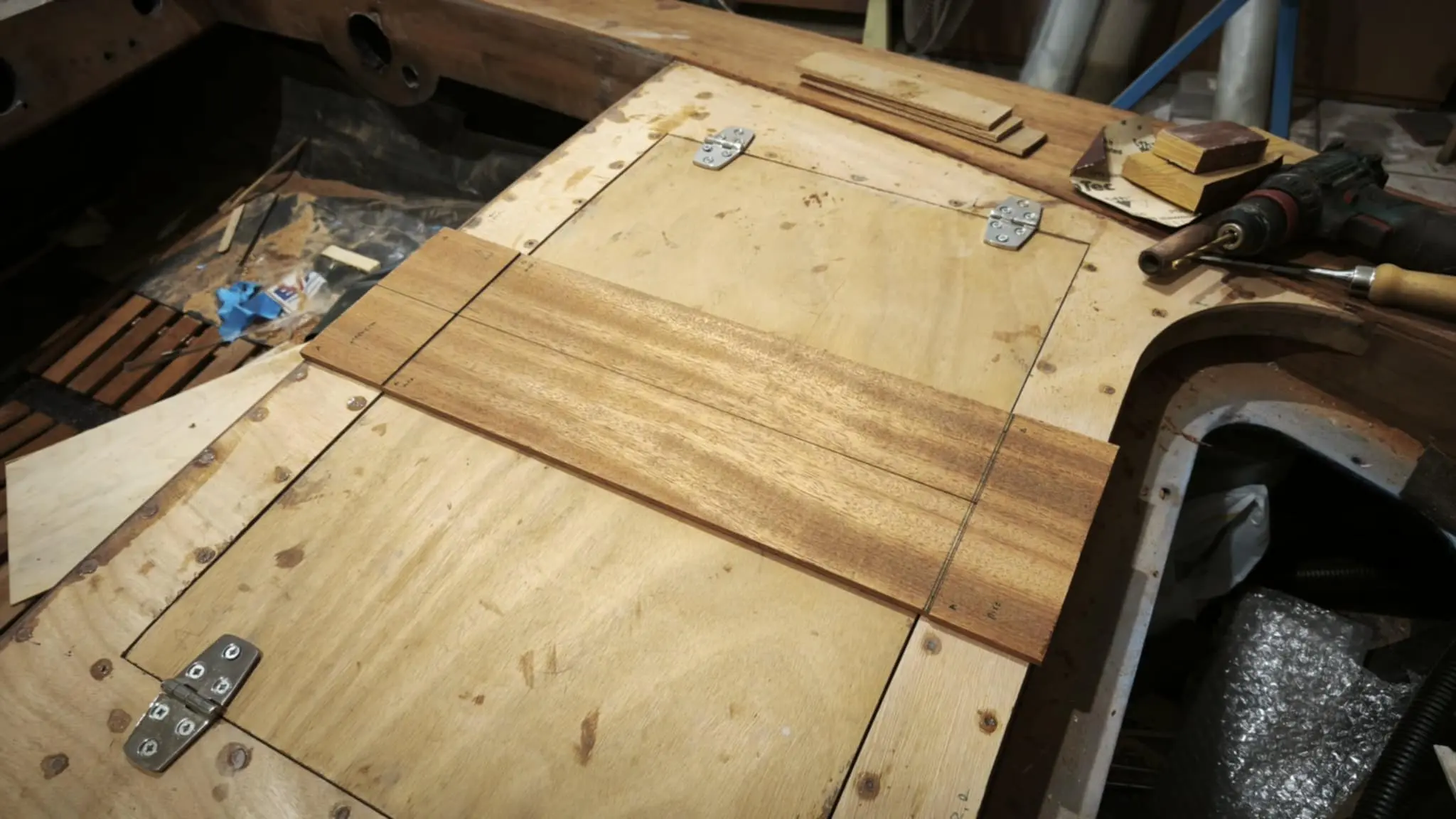
After a good deal of thought, and because the plywood I had was a particular size given the cuts I had already made, I decided to use 5 pieces. One aft, two in the middle (left and right) and two large ones forward.
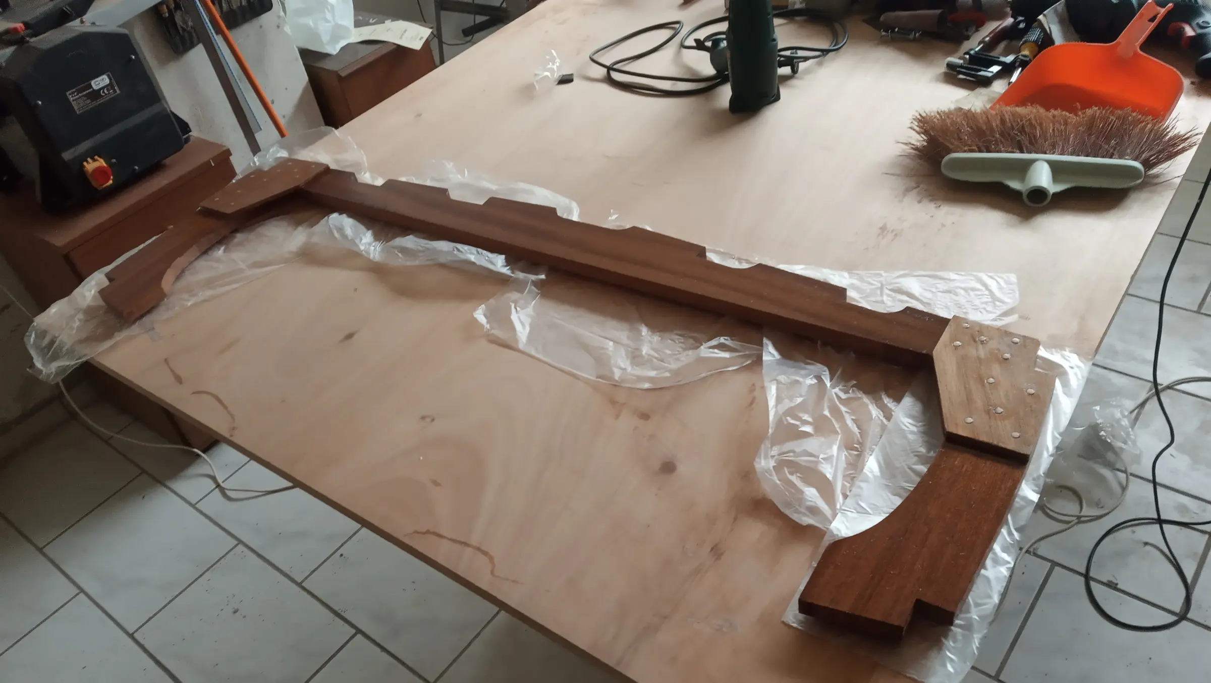
The pieces were cut roughly to the dimensions I wanted. At the aft end I used clamps to press the plywood into the curve.
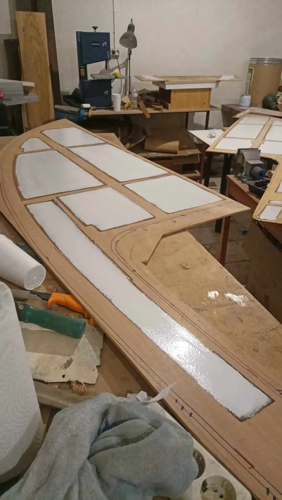
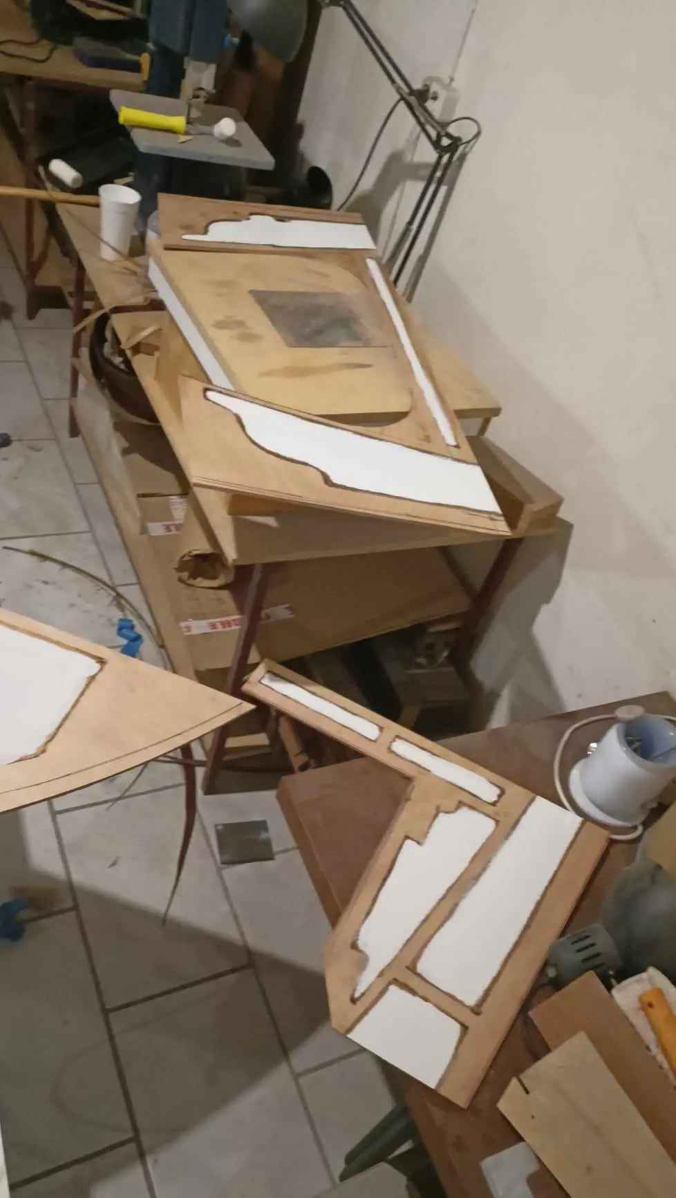
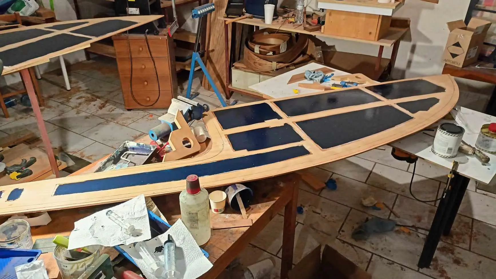
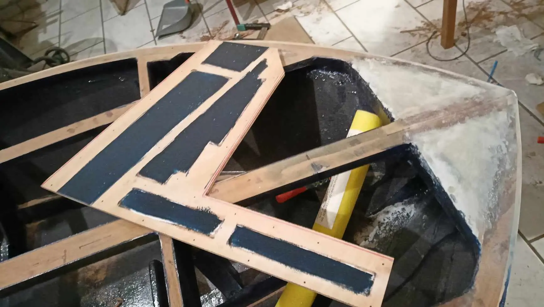
Once they were clamped I marked from underneath the areas that would be glued, so I could coat the rest with resin, primer and paint for protection.
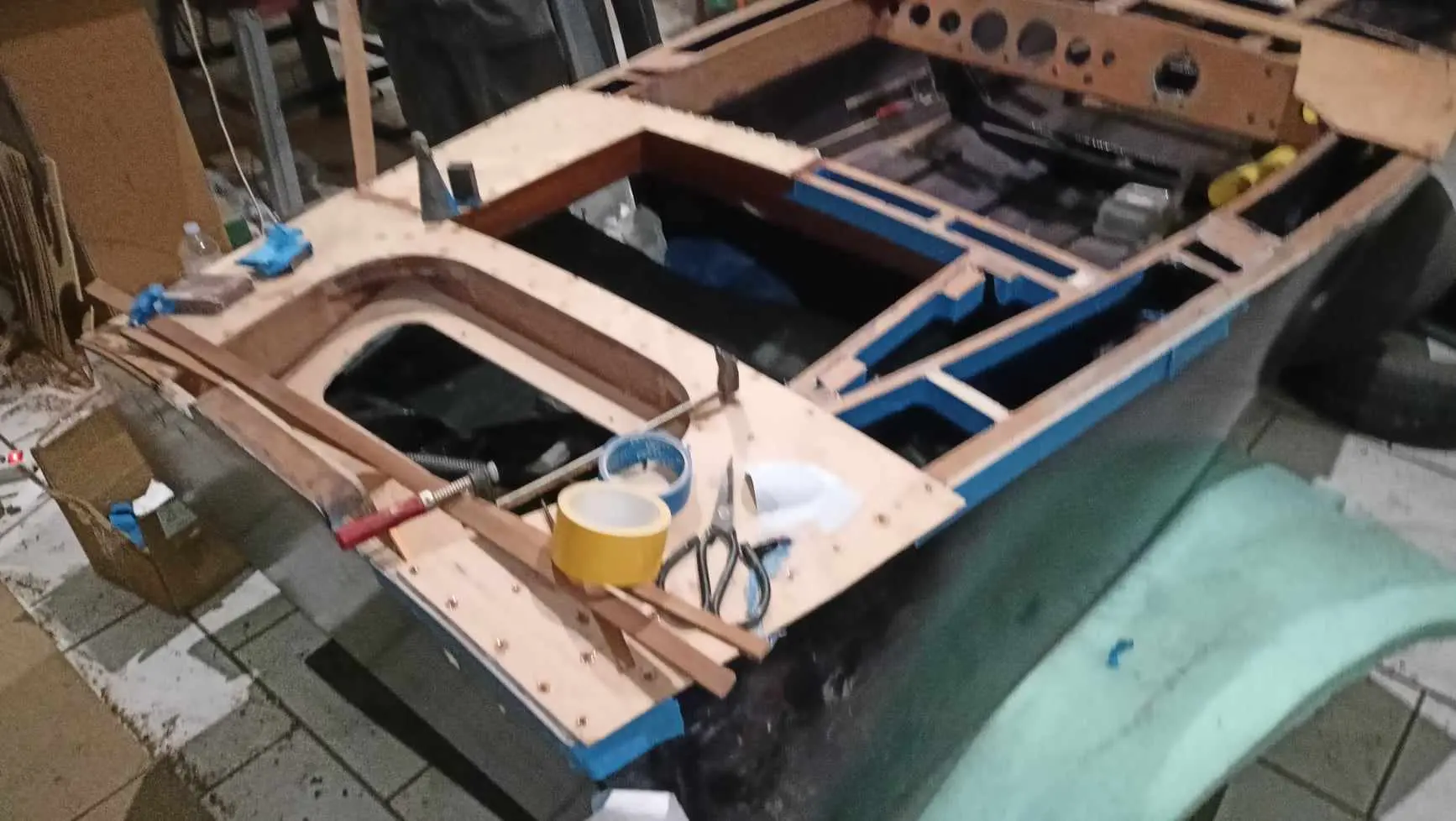
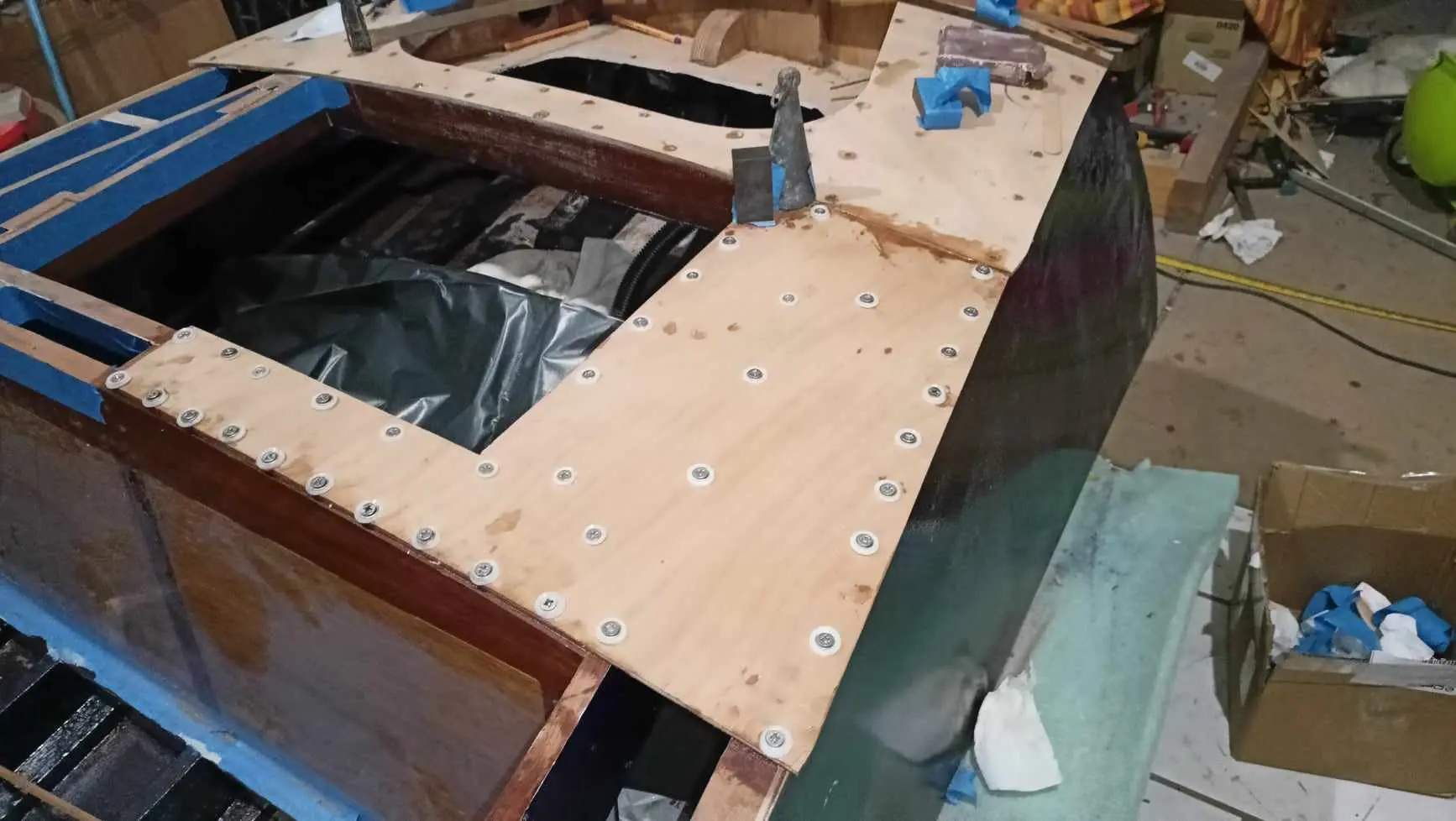
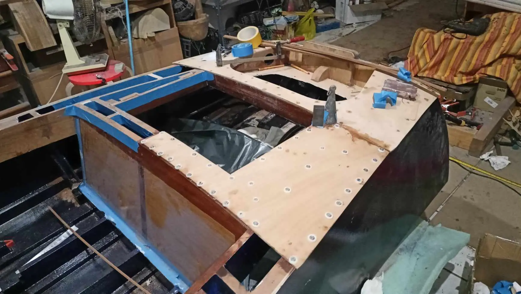
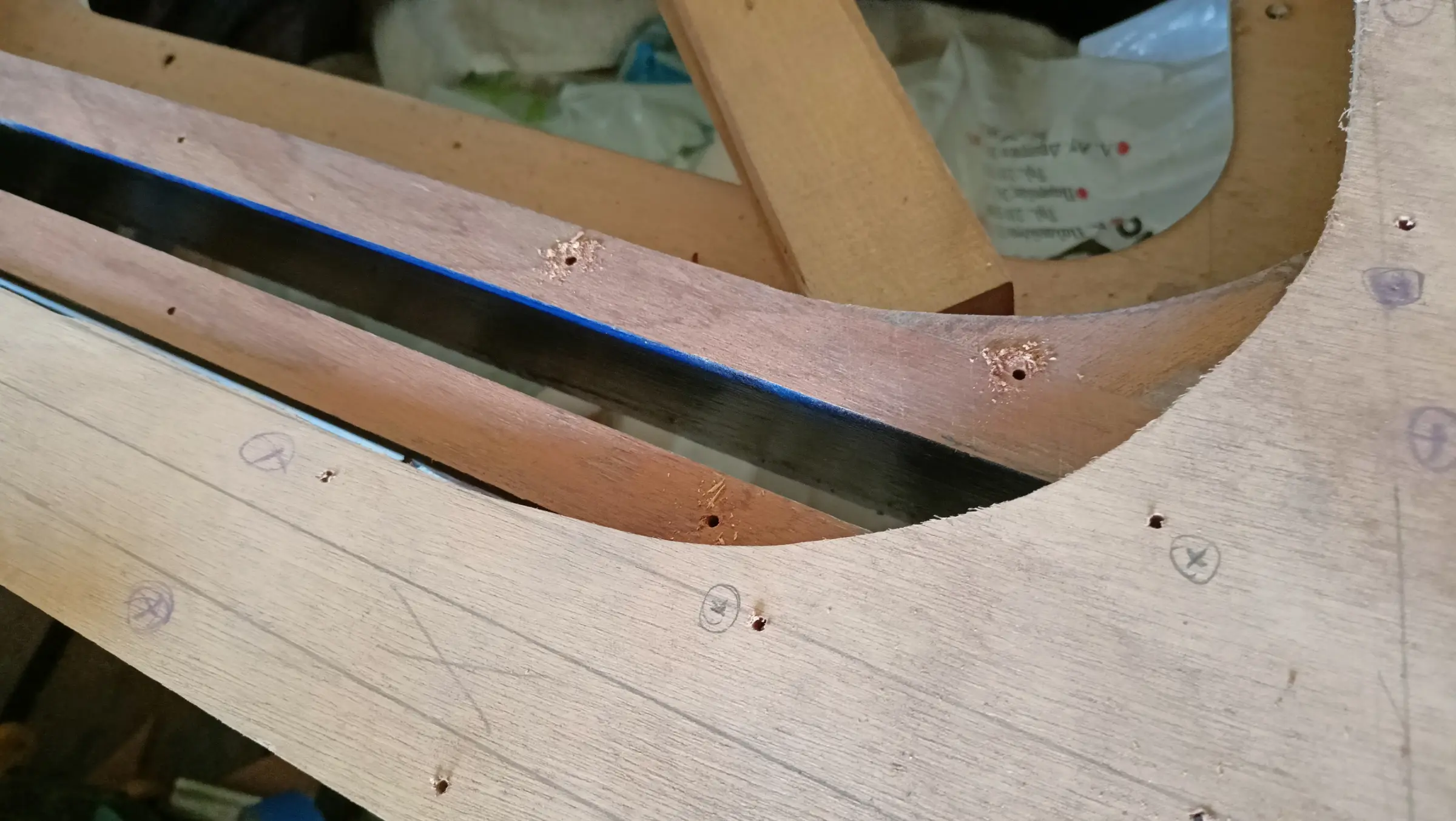
I started gluing at the aft end. It was clamped in its exact position and small holes were drilled with a 2 mm bit at a number of points. Then masking tape went on so glue would not run, and the glue was spread on the areas to be bonded. I had very carefully transferred the glue areas to the top face so I knew where the screws would go.

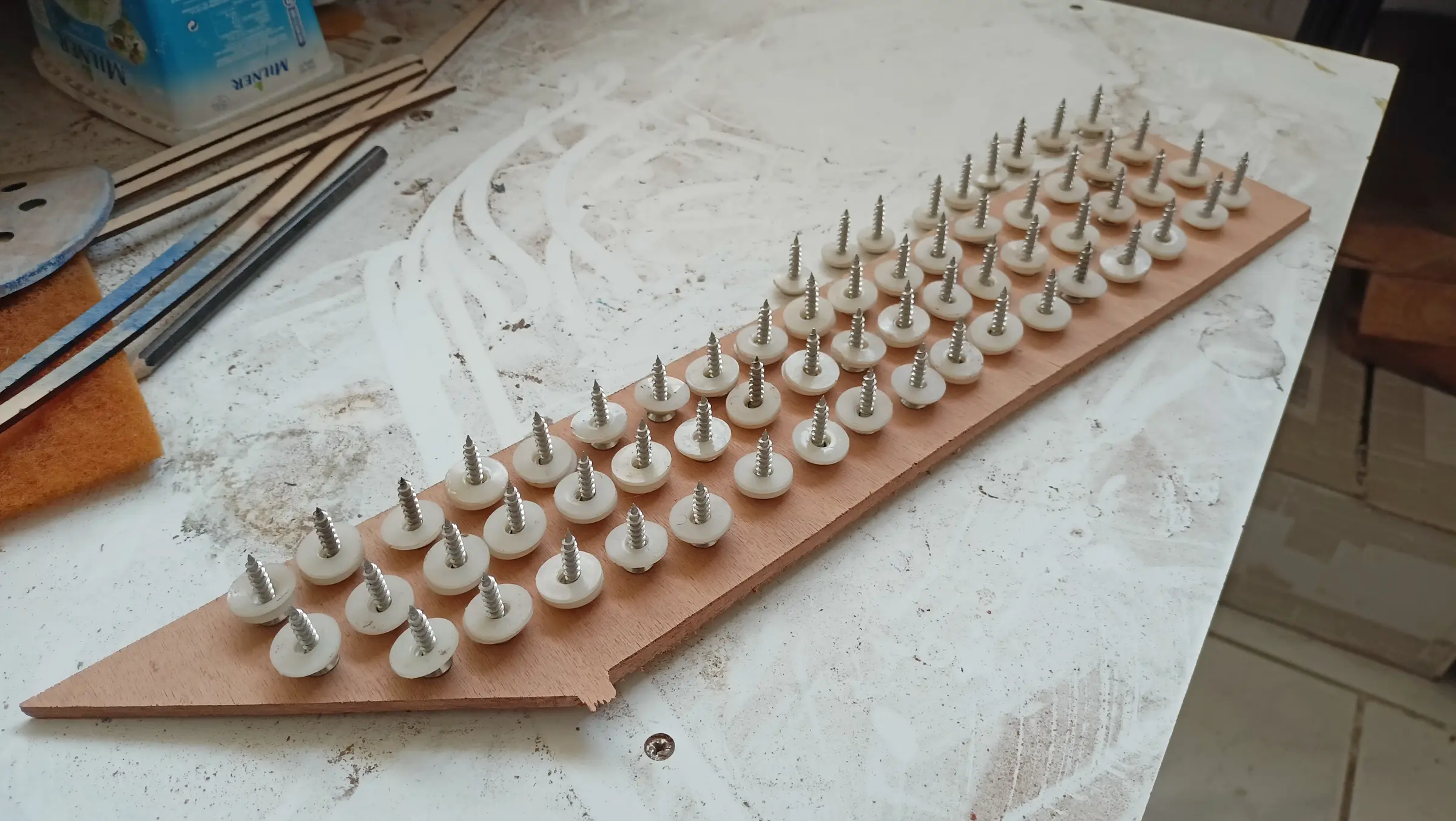
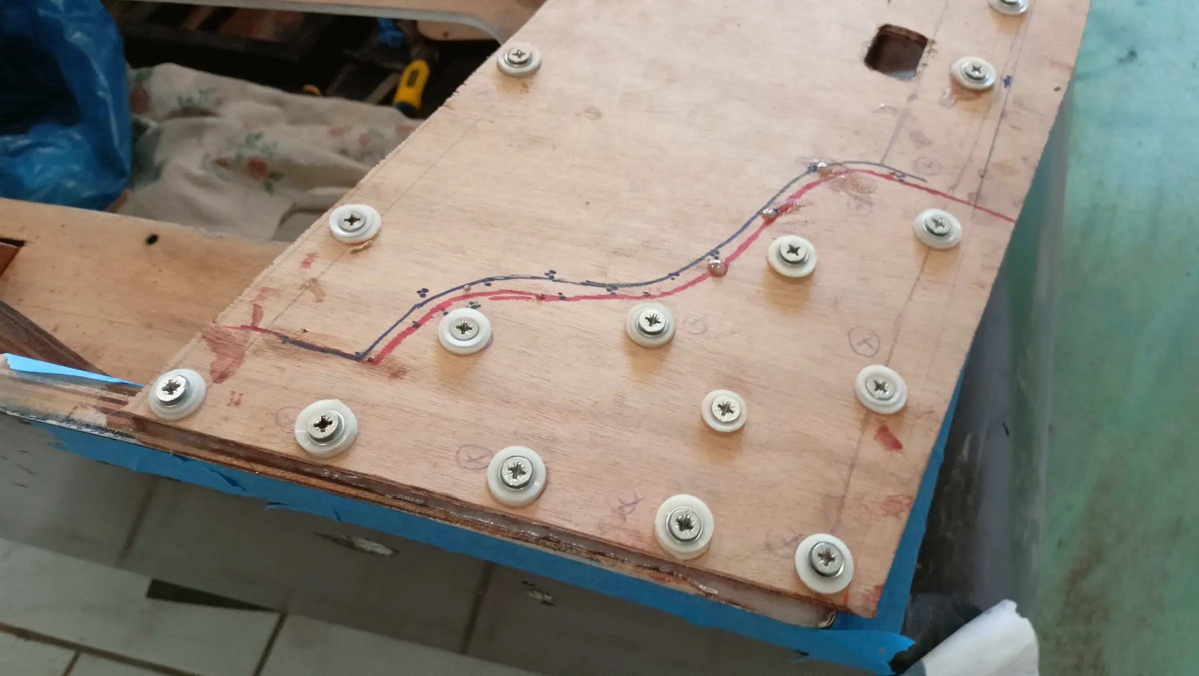
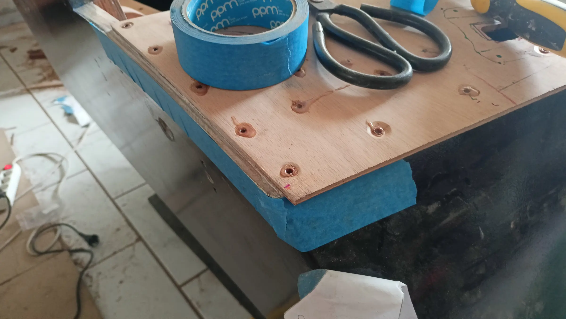
The drill bit itself was put into the holes that had been drilled, to hold the plywood in position, and then it was screwed down. To give the screws minimal contact with the epoxy I used plastic washers. After a few hours the screws have to be turned very slightly to break the bond, so they do not stick even with that small amount of contact with the resin.

Once the plywood was fixed in the right position I opened out all the holes the screws would go into with a small drill. That was both so the screw goes in easily and, mainly, so I have the exact point it will go in.

As can be seen in the last photograph, the plywood did not go right to the end of the boat. At the end, because the plywood would look bad, a sipo fillet will go on.

The same process for the middle piece, but with two pieces, one left and one right.

Because the seat is at the forward end of the central plywood, I decided to put a solid timber fillet here as well.

Before moving to the forward end I drilled a hole in the aft plywood for the control cable to come out of, and then completely shaped the inner edges of the middle pieces where the locker doors will go.

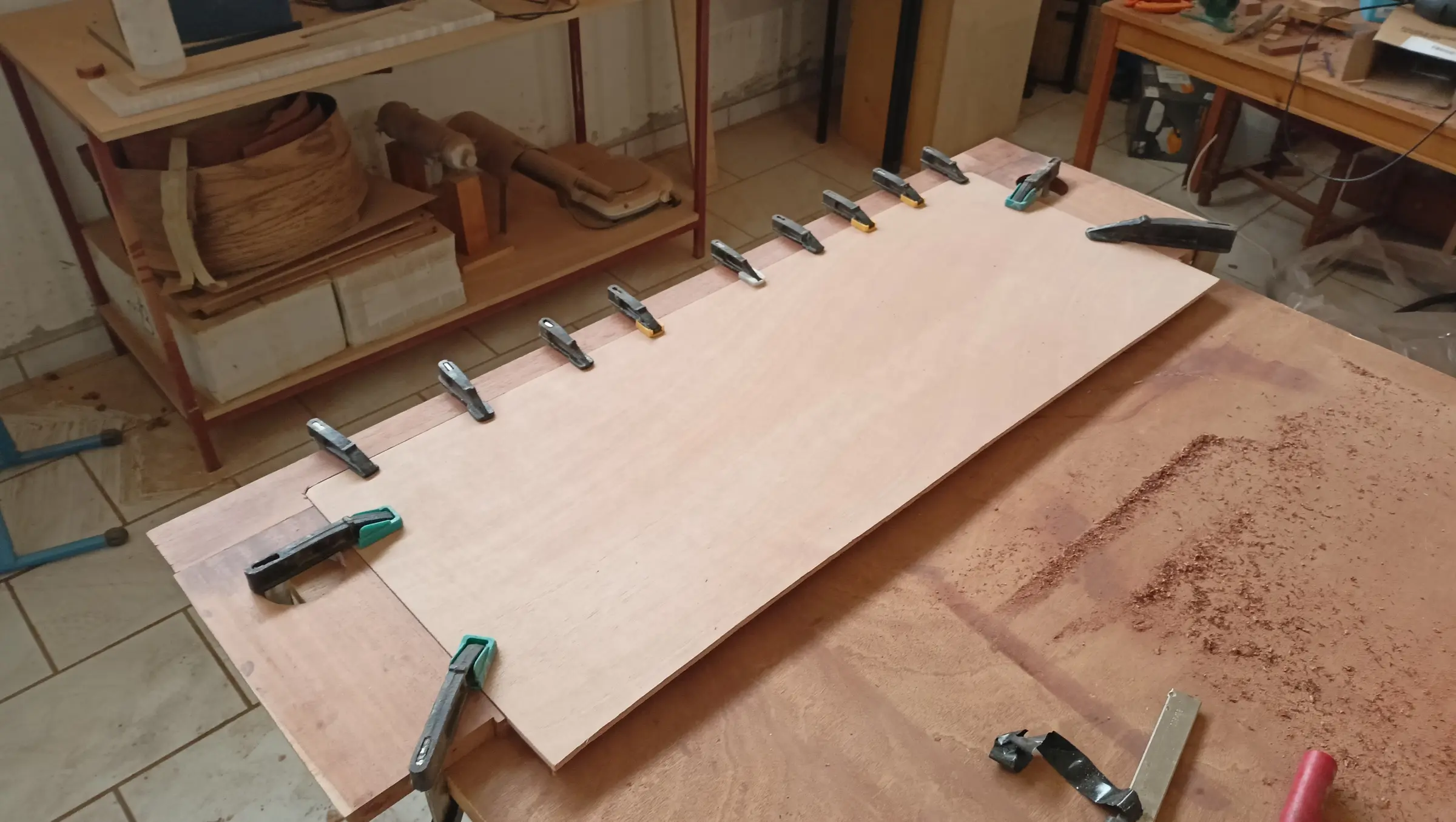
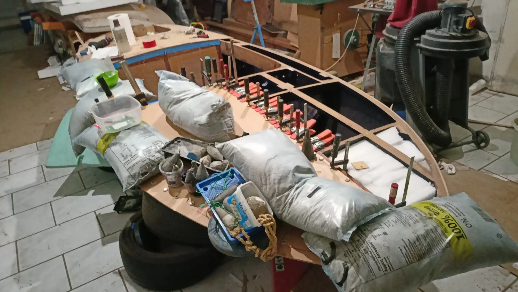
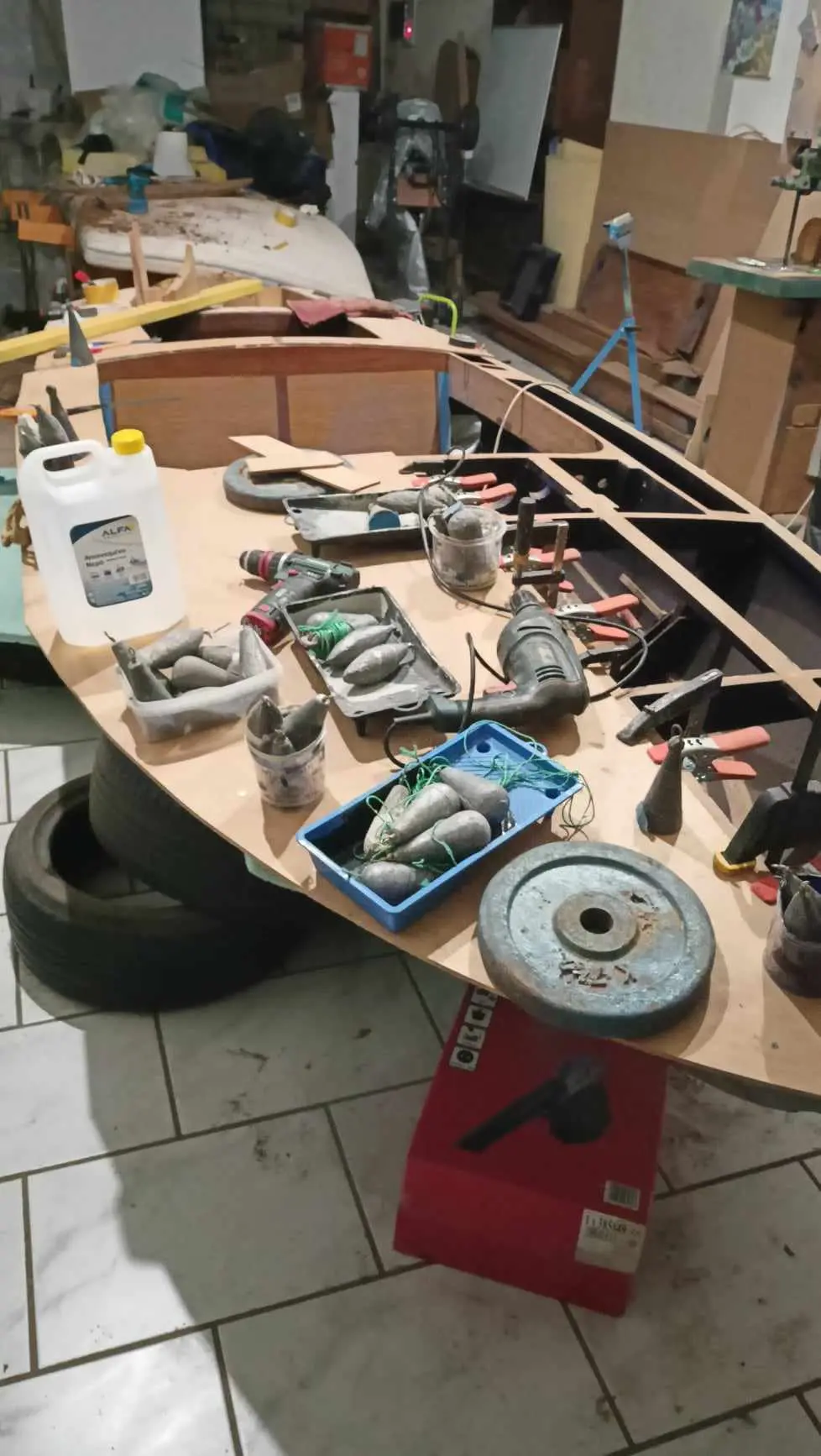
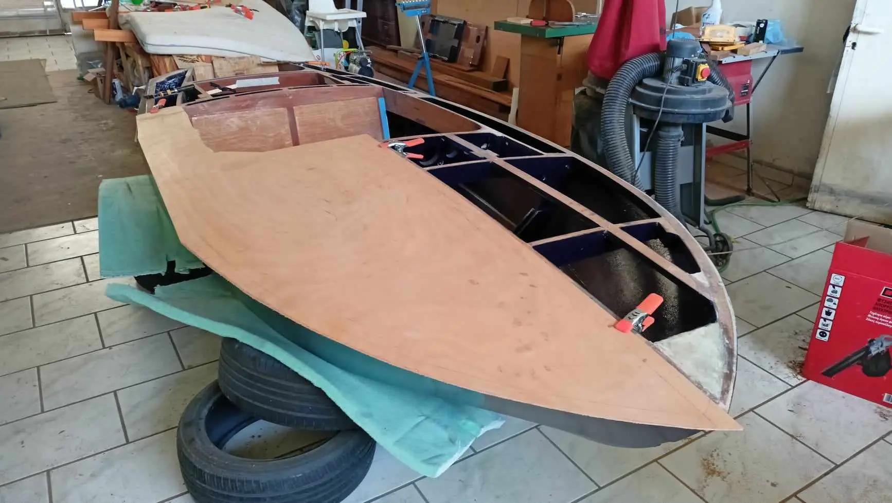
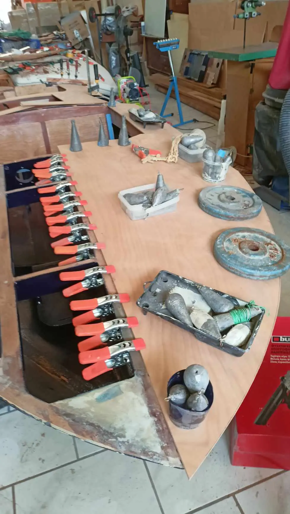
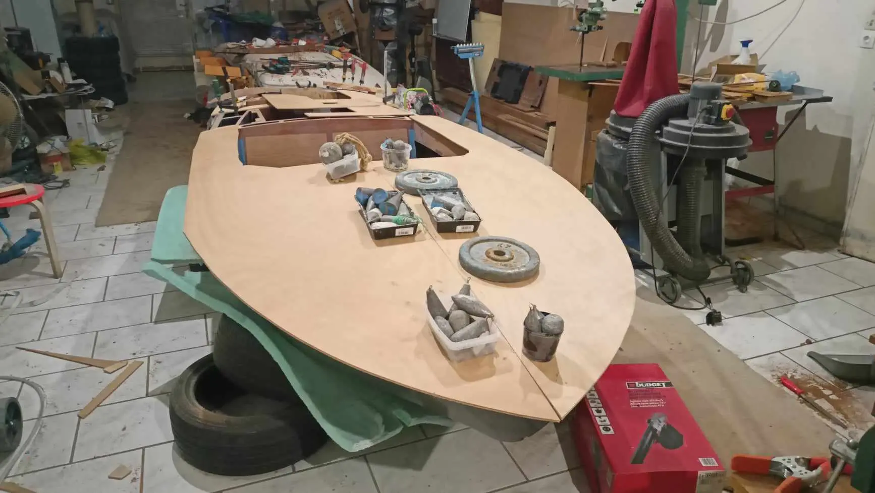
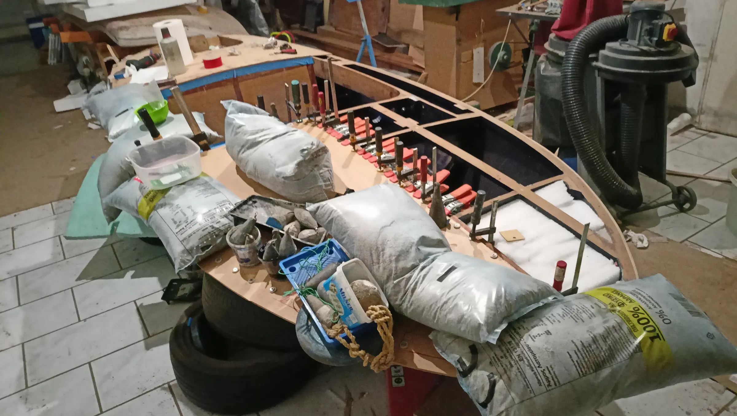
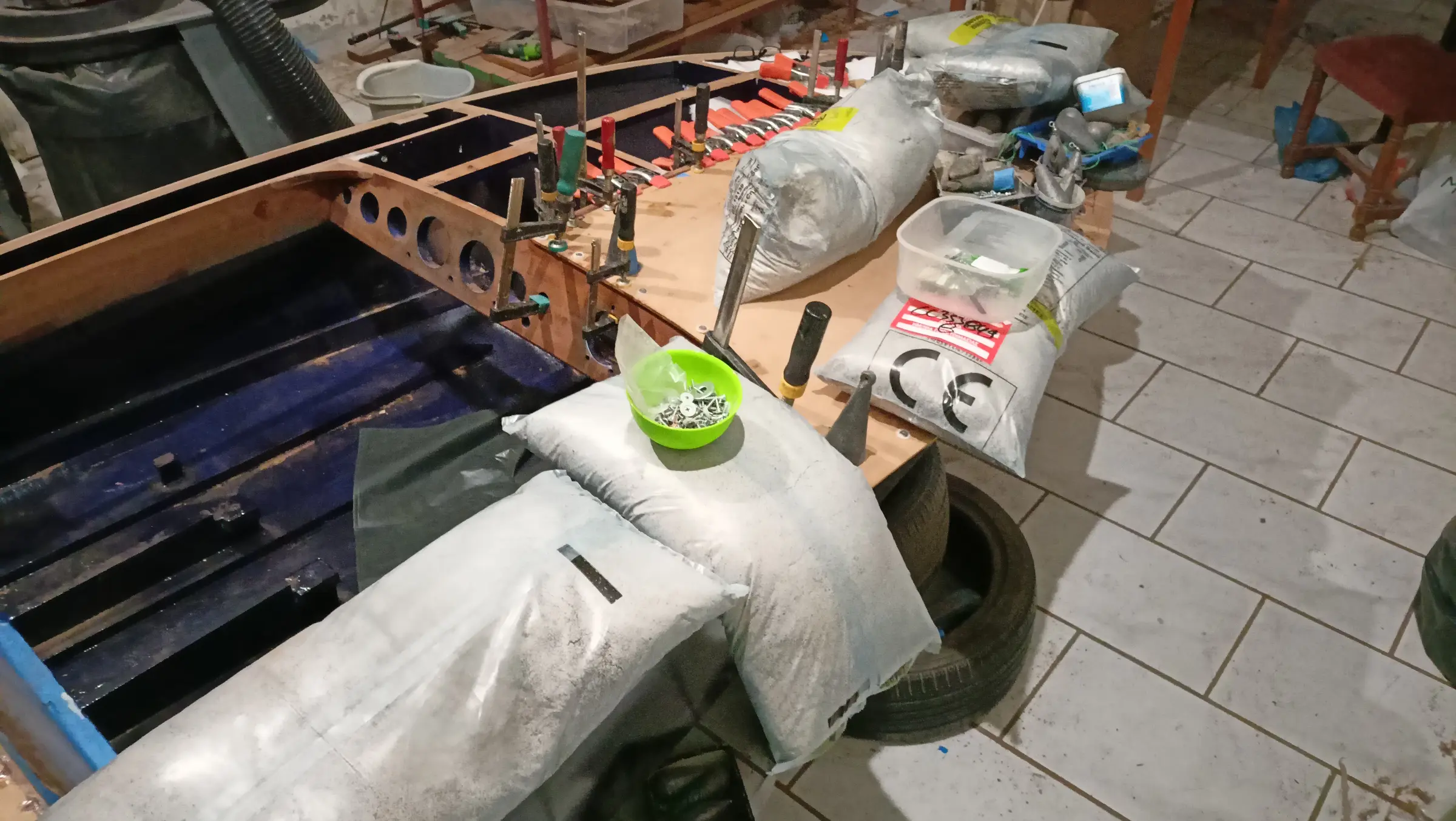
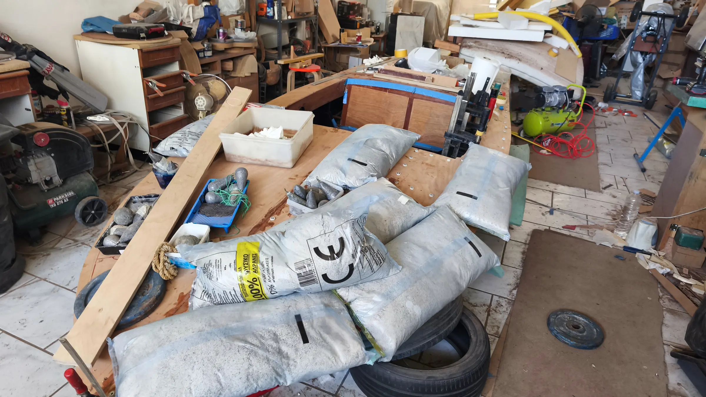
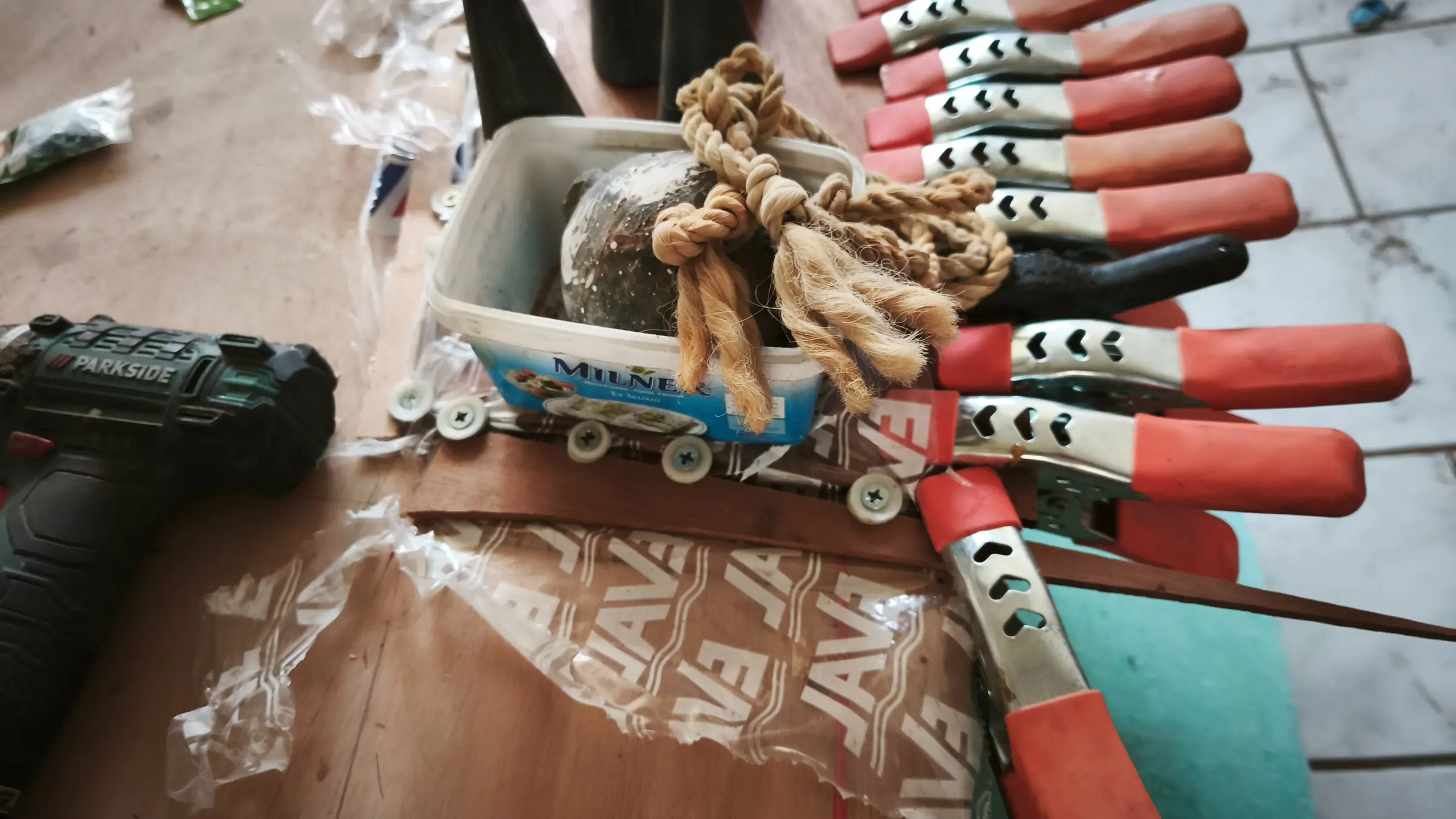
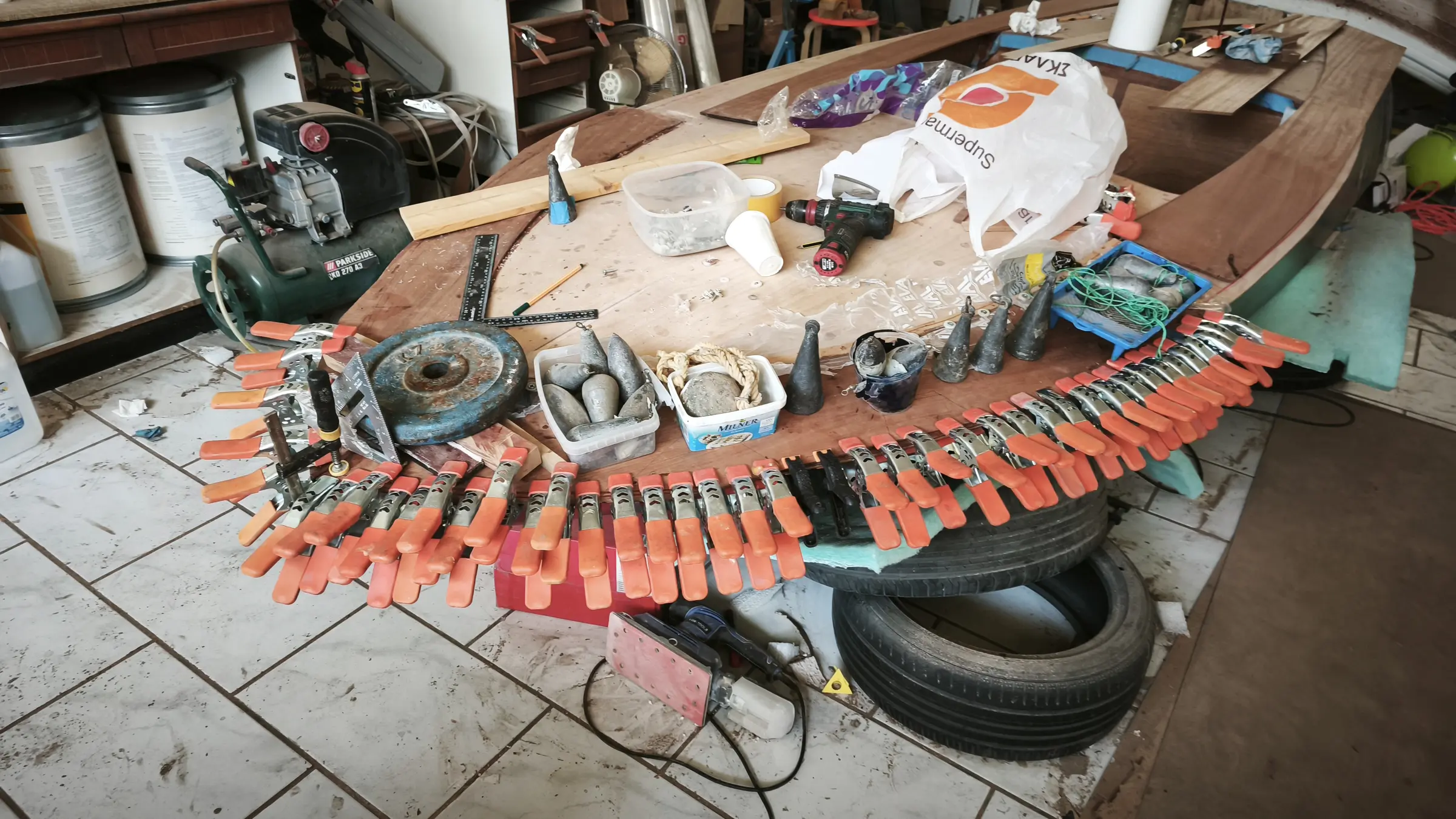
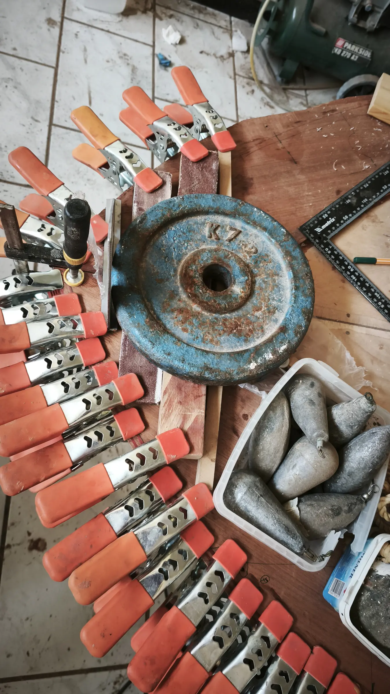
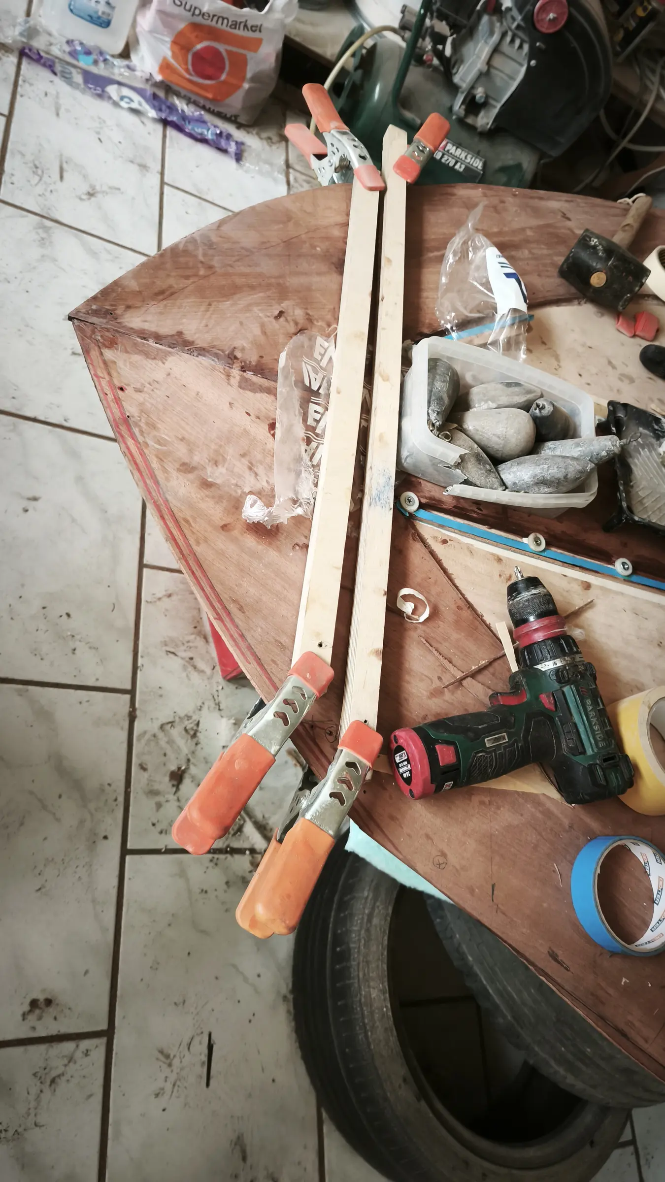
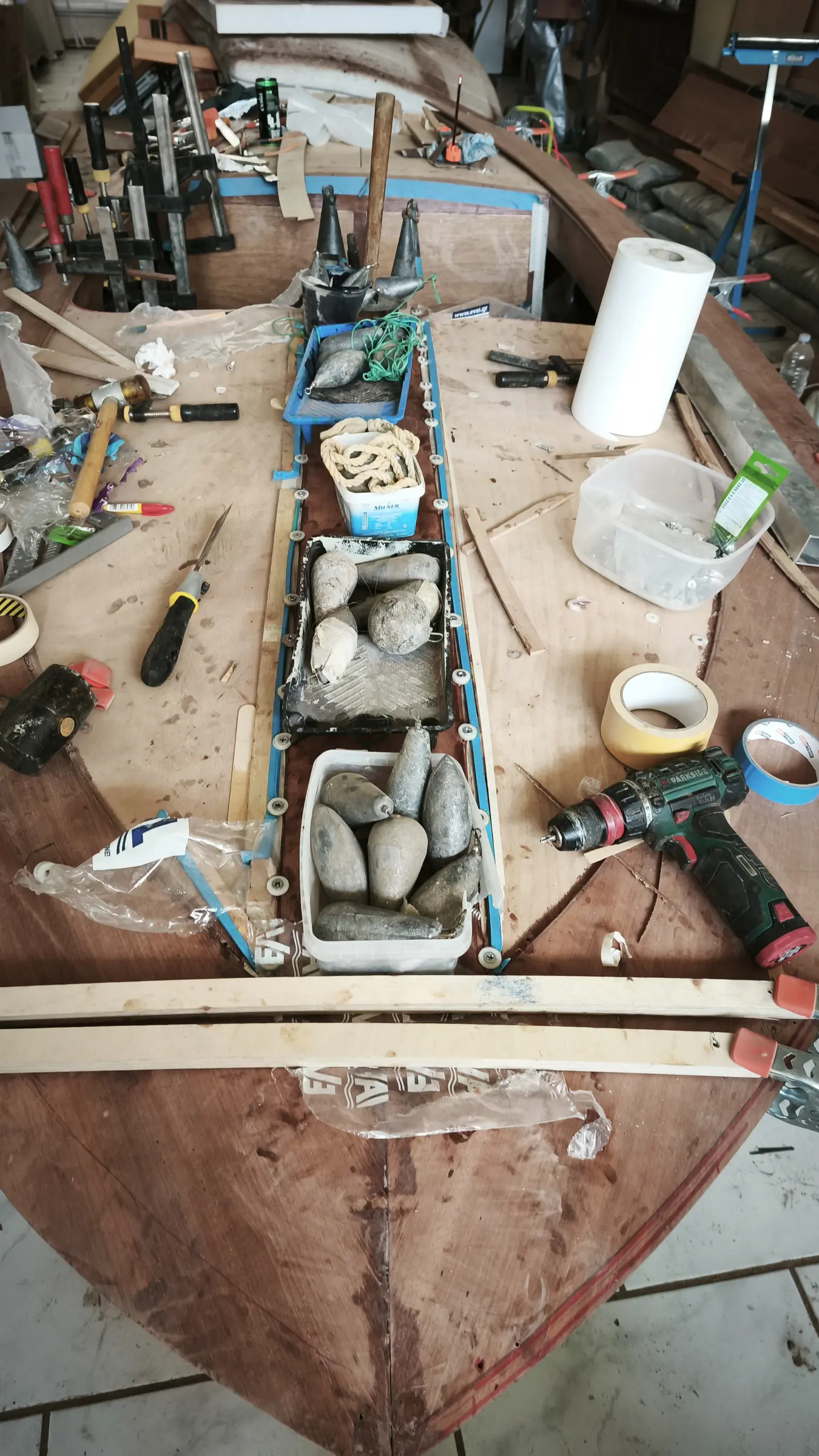
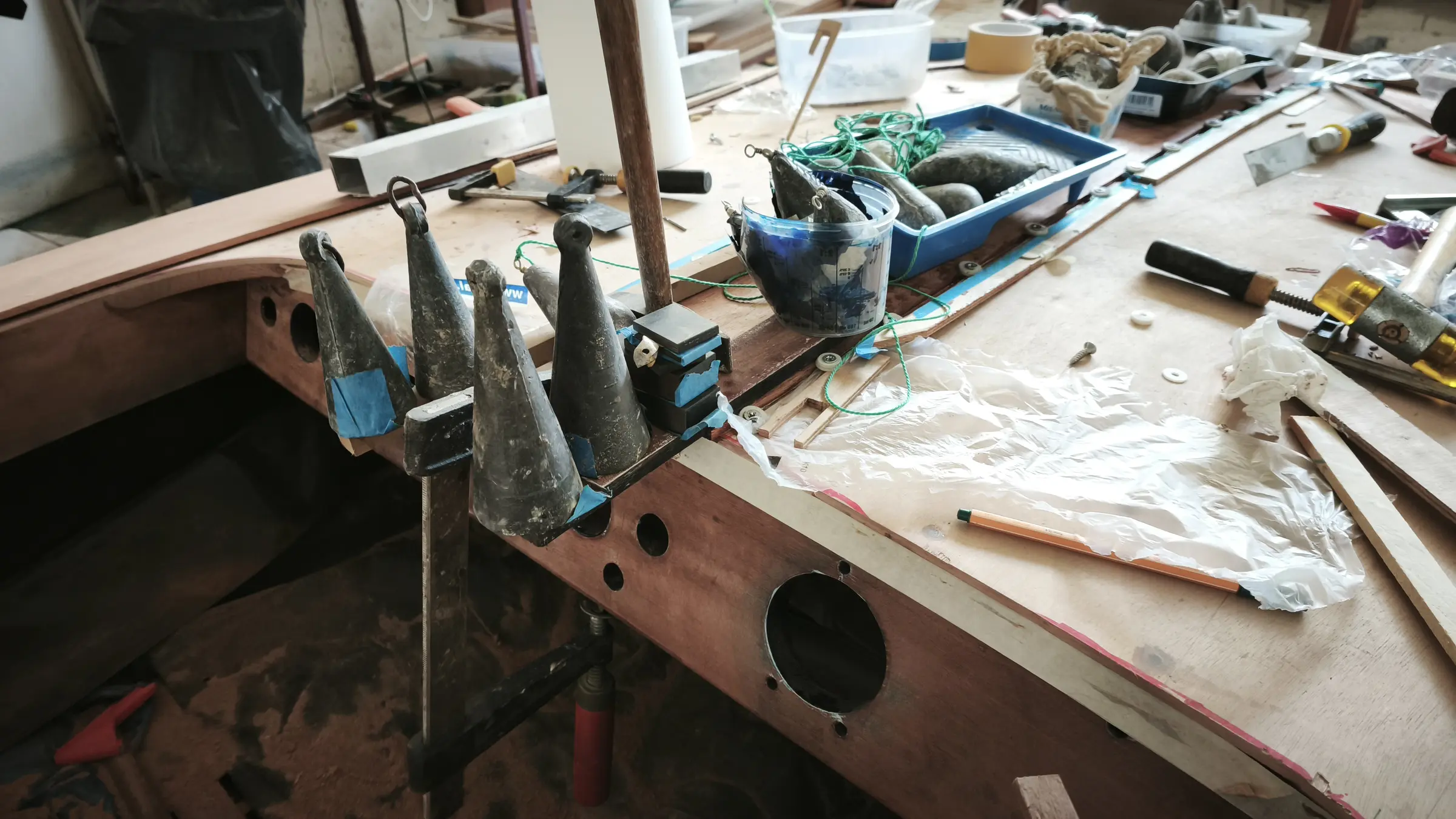
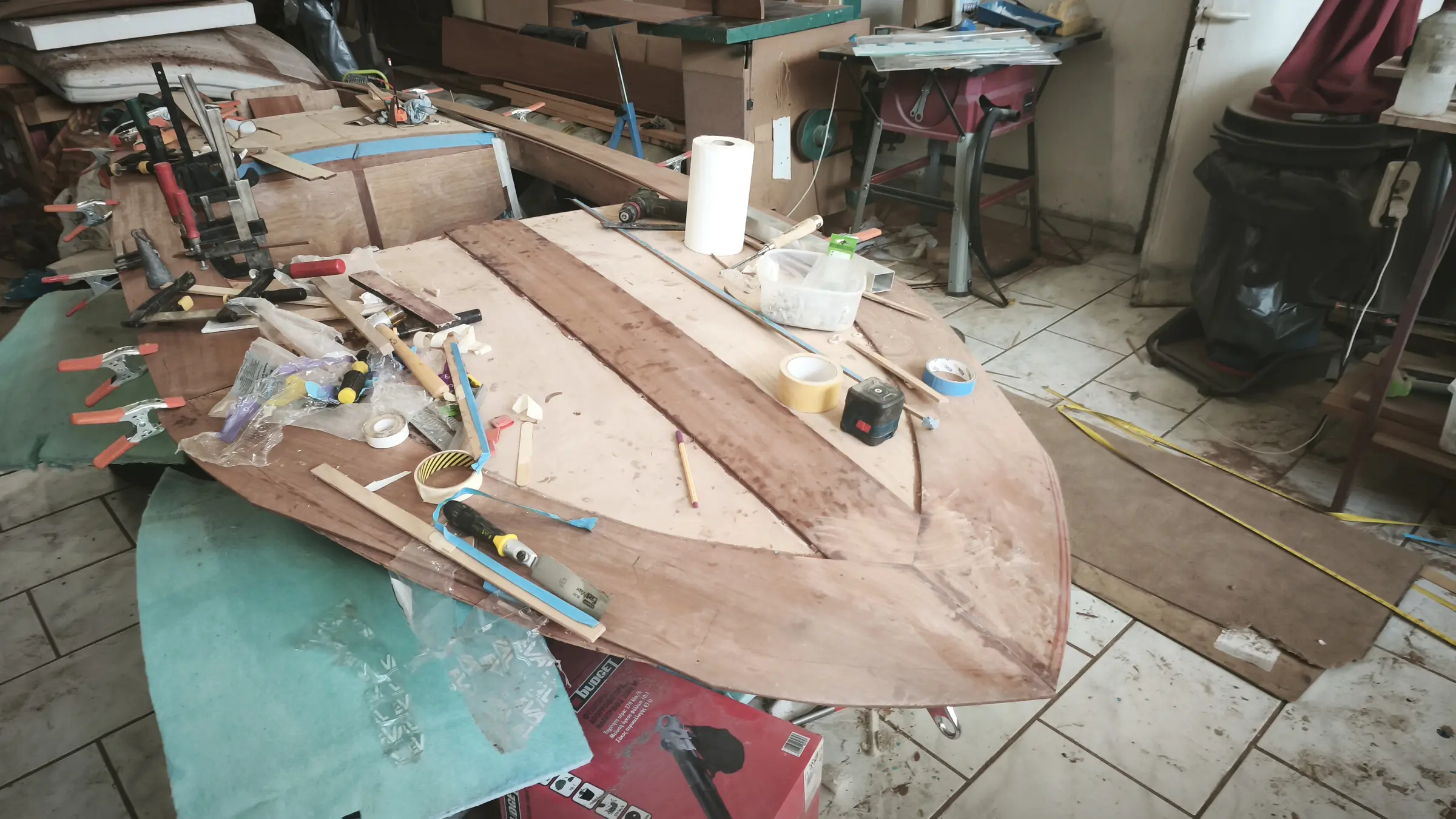
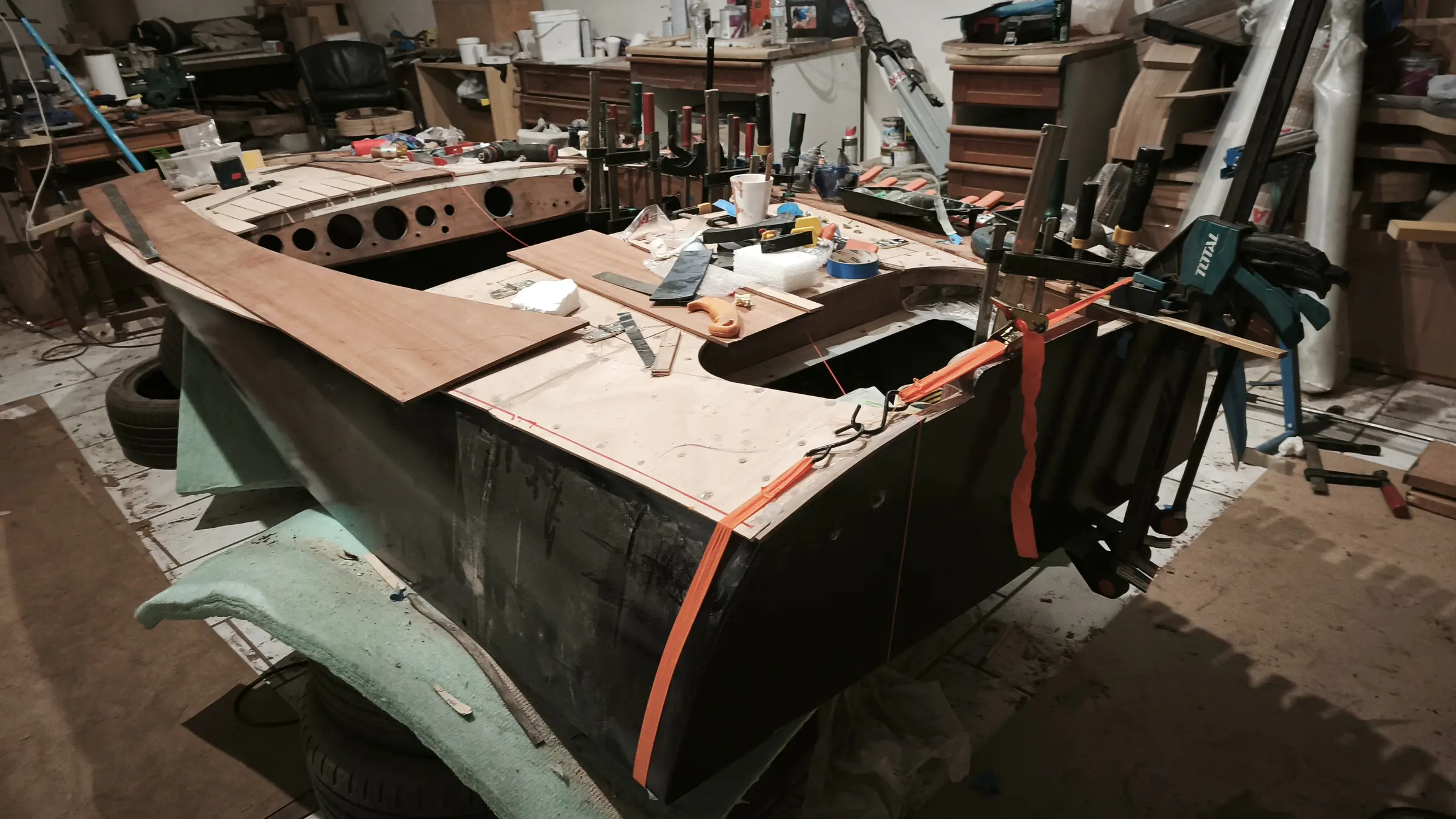
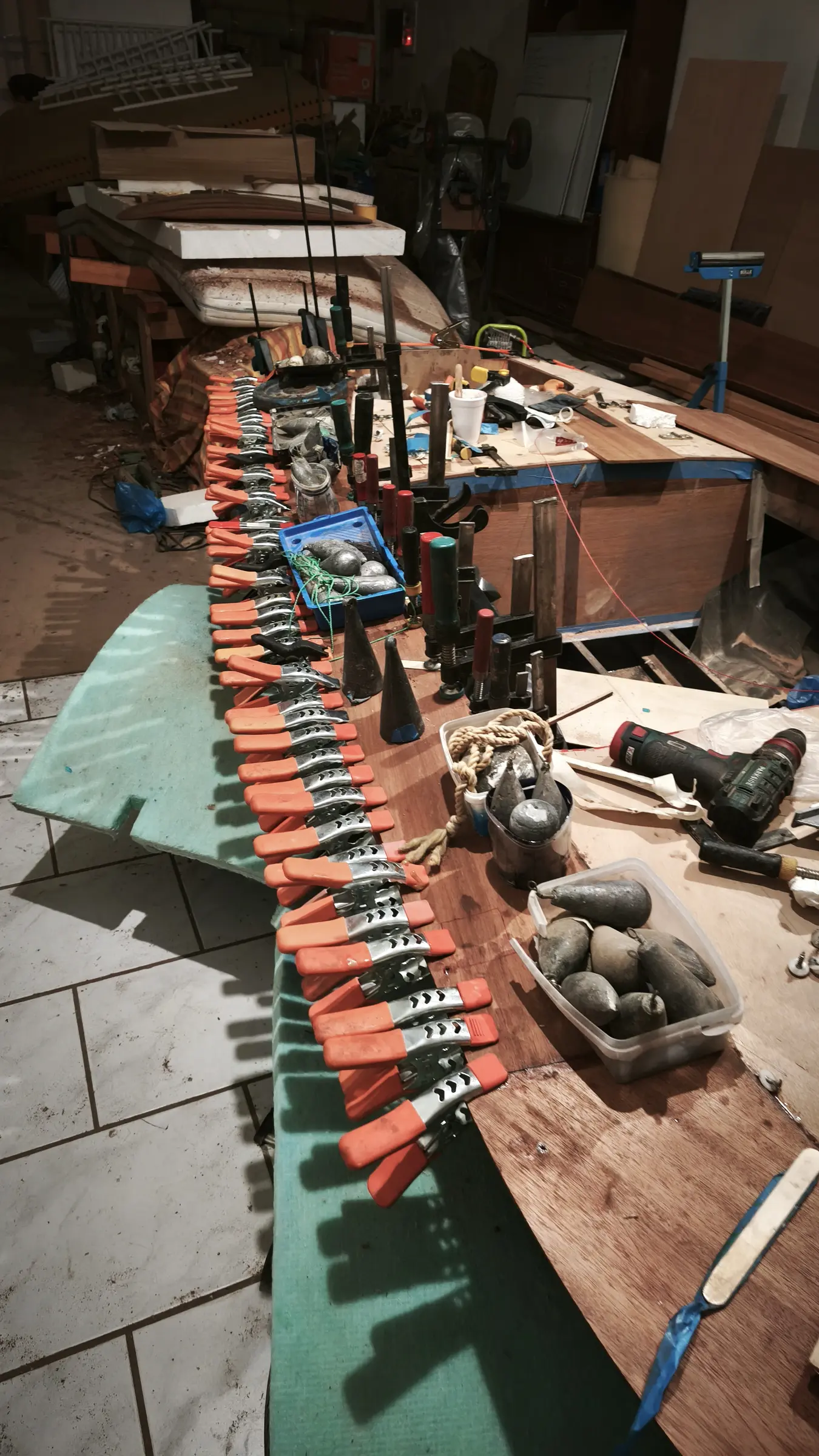
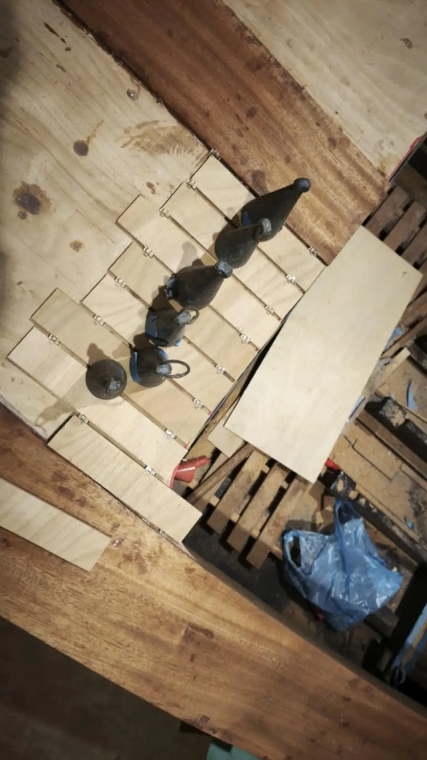
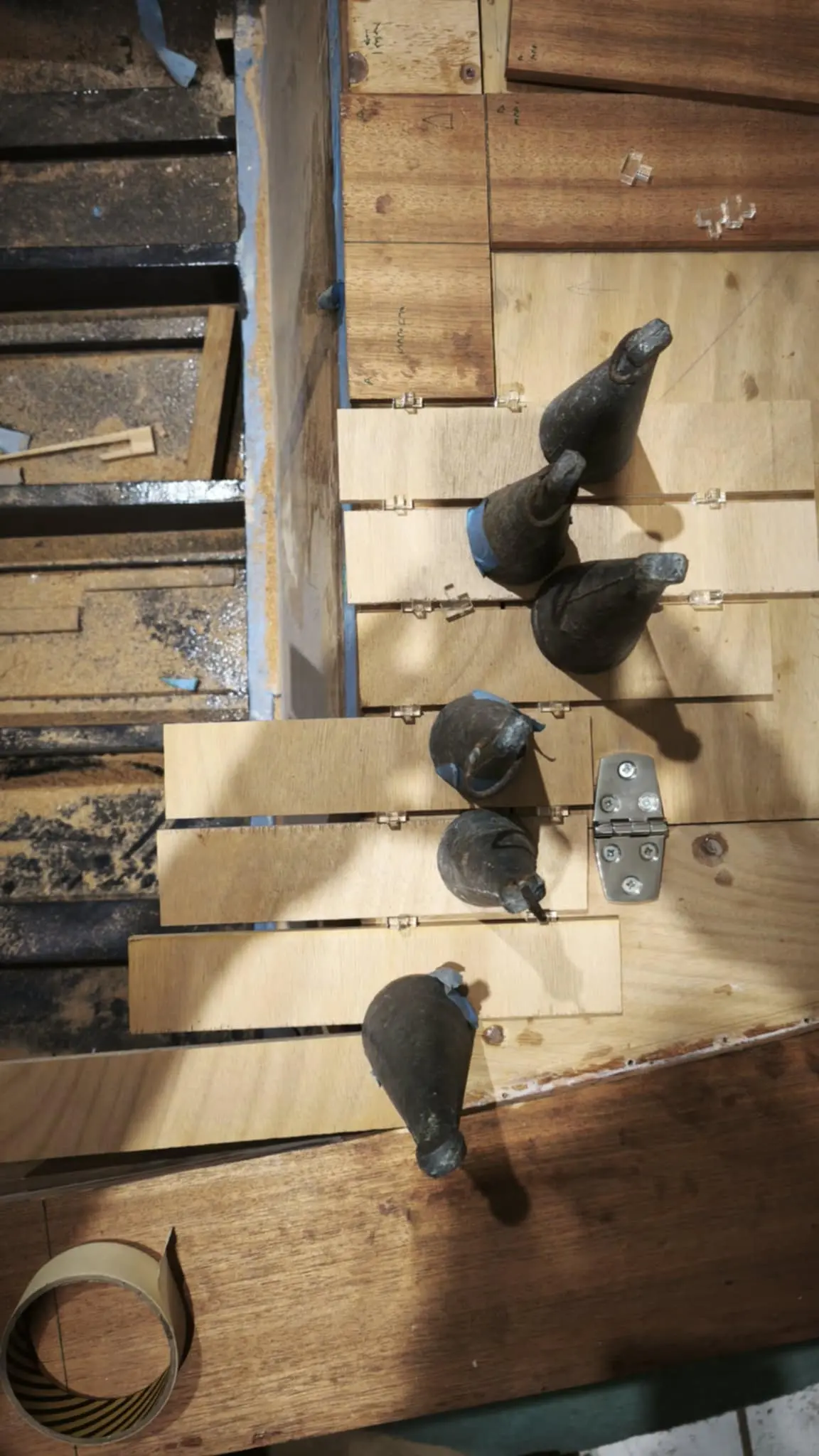
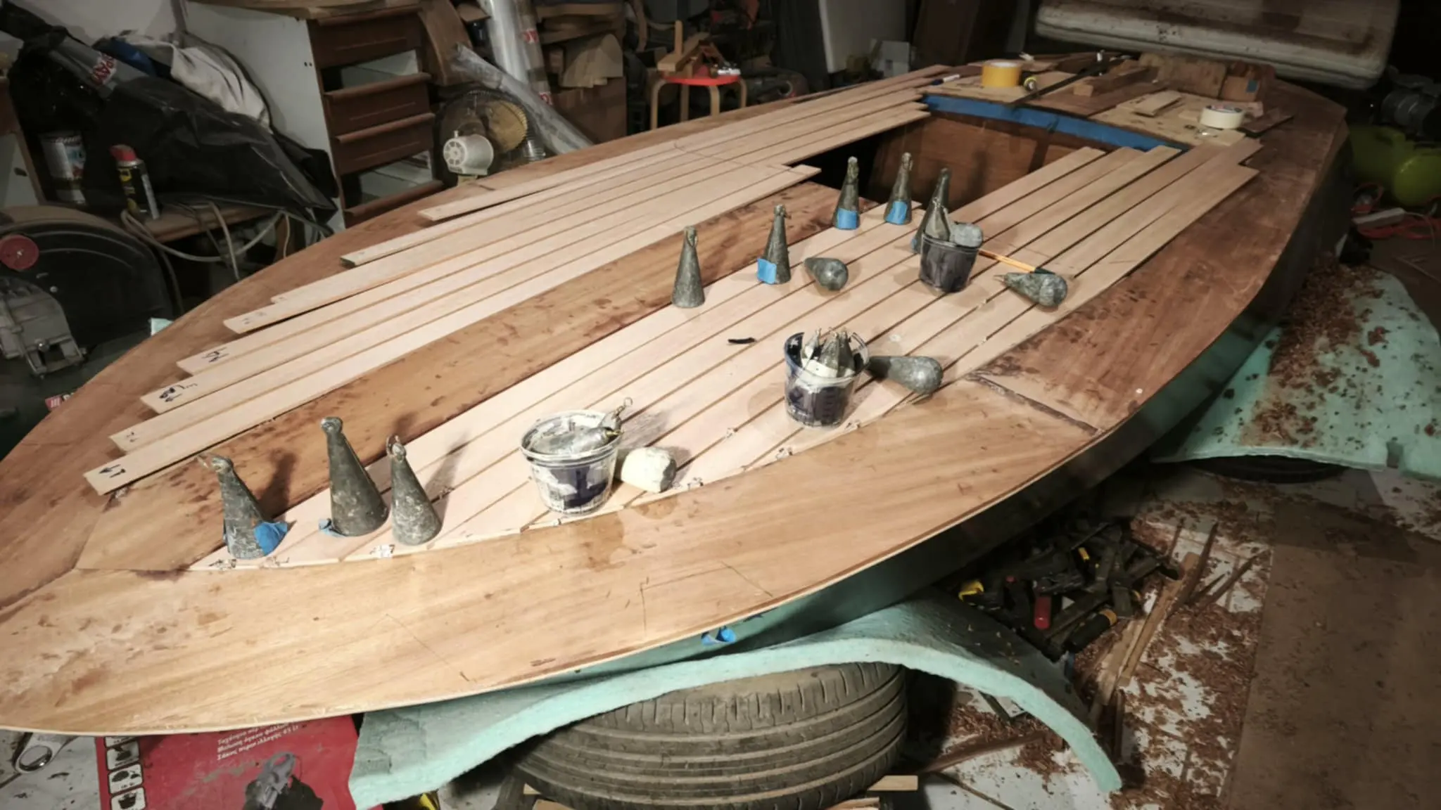
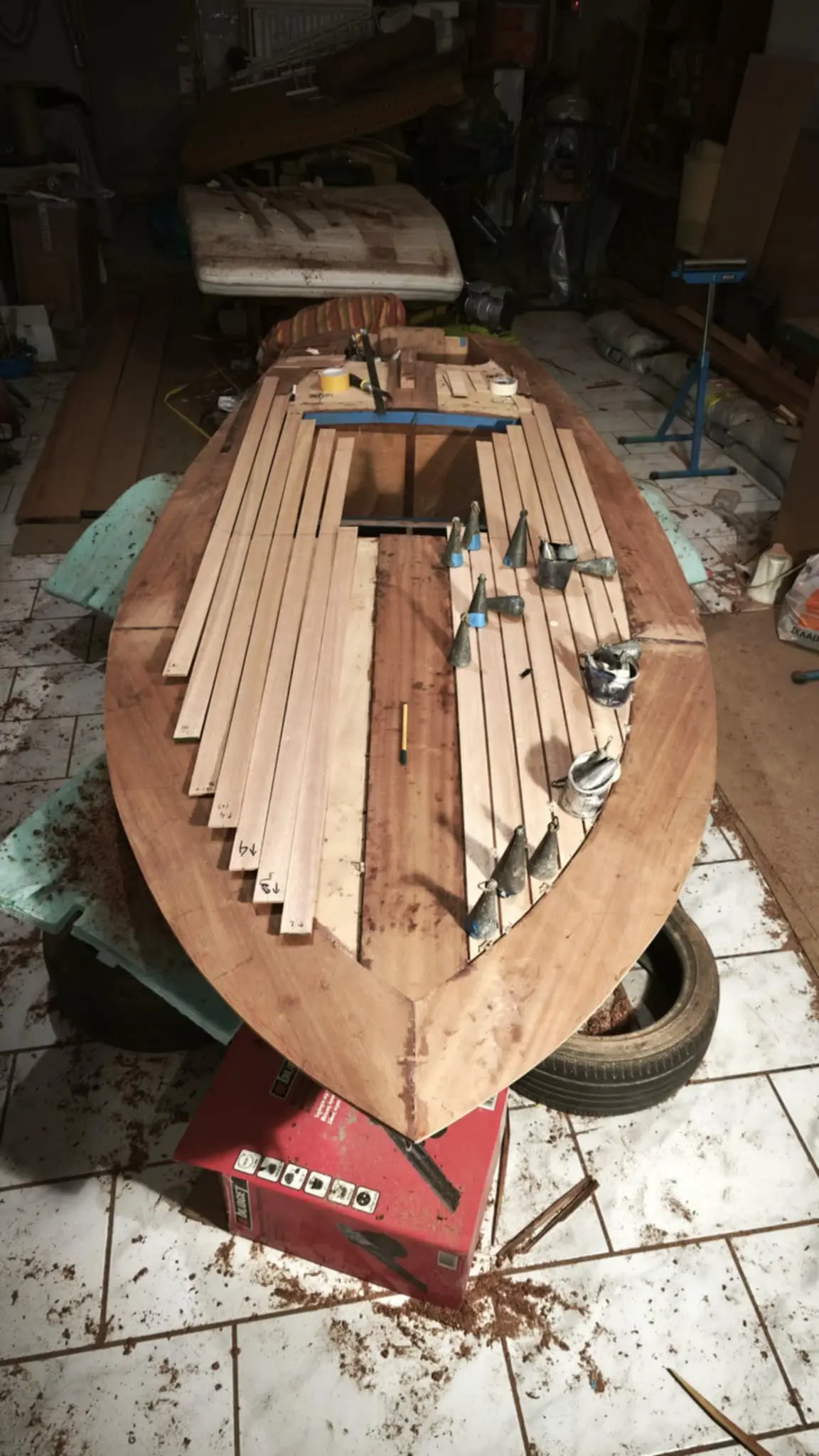
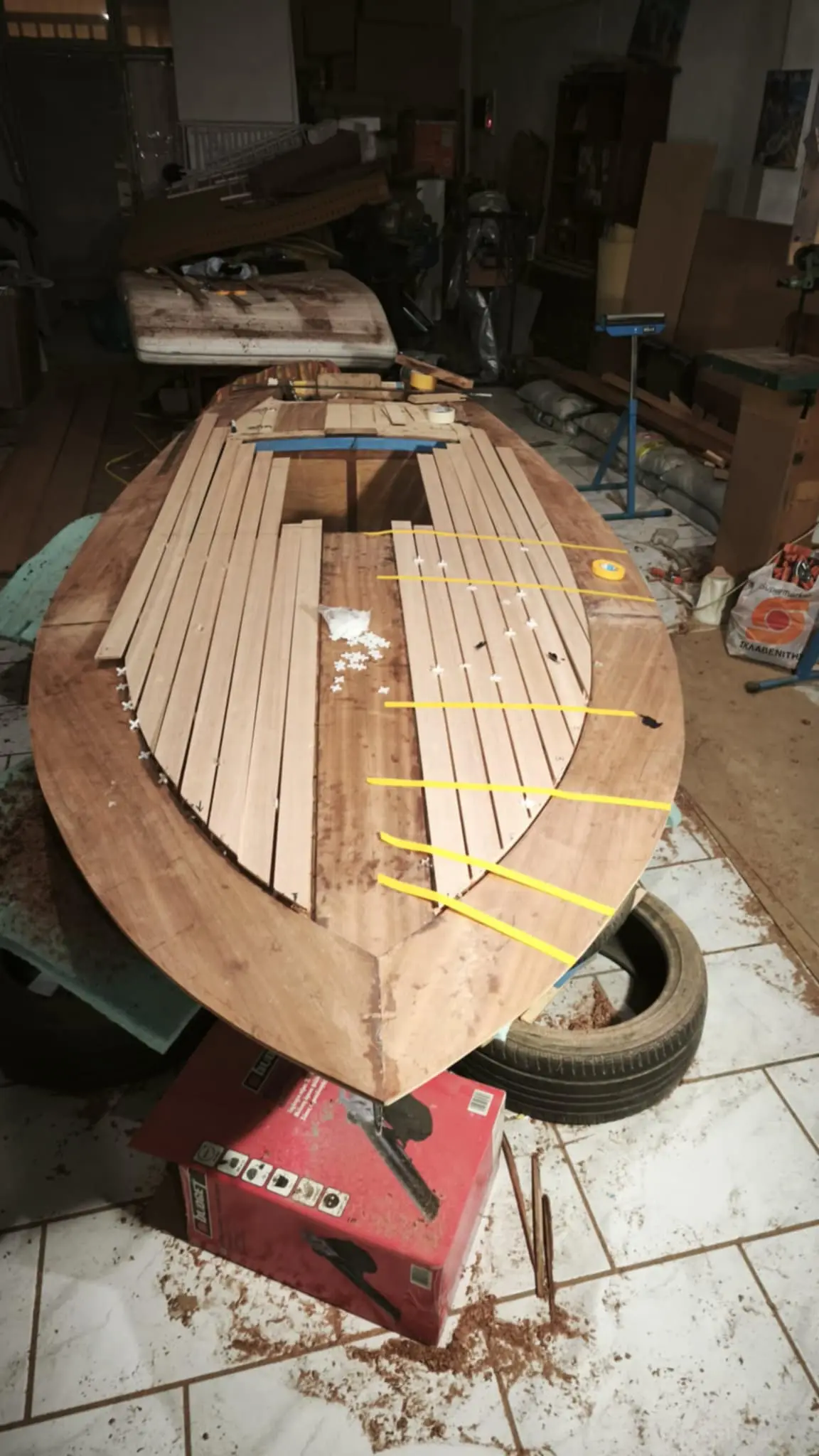
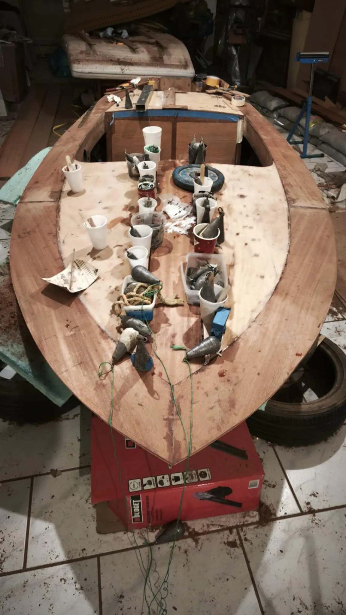
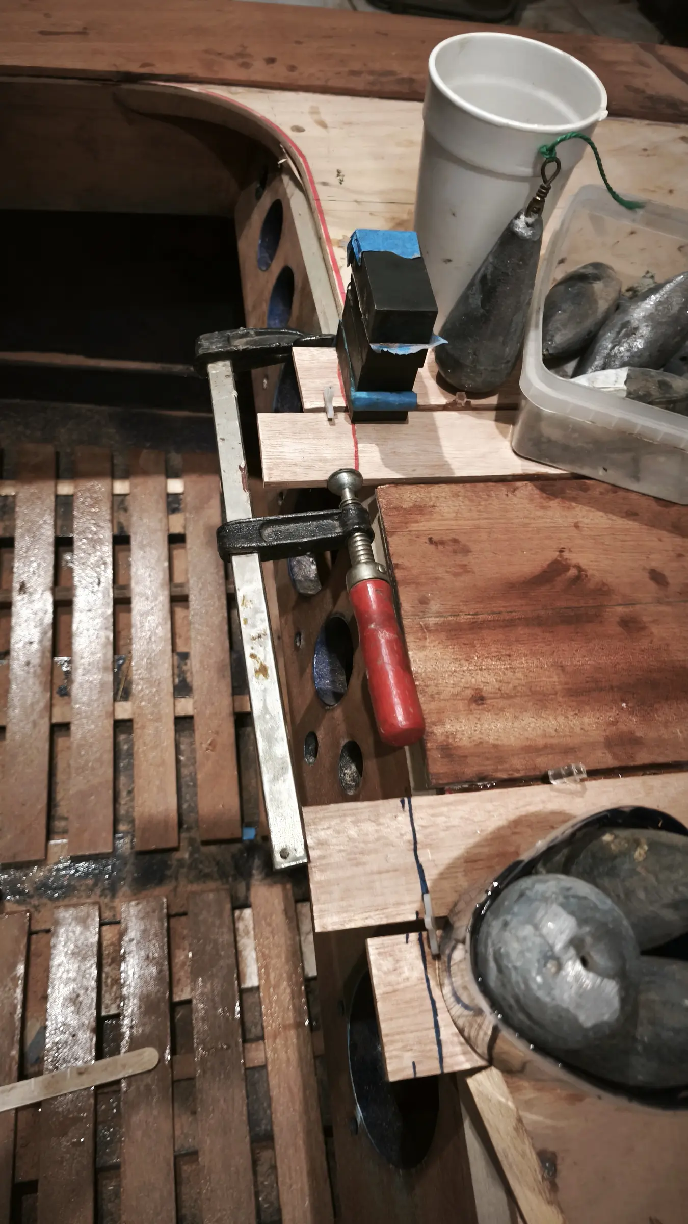
Next comes the forward piece. The main thing at the forward end is to cut them as perfectly as possible where they meet on the centreline. A rasp was used to get a completely straight edge on the first one. I did the same again. There is a peculiarity here in that the forward mooring cleat has to go in first and then the flotation material, so it does not make life difficult for me later given how little working space there is. At the forward end of the boat the plywood has quite a pronounced curve. I decided not to rely on screws alone but to use plenty of weight to help the wood bed down onto the framework timbers. I will do that with a lot of fishing weights, dumbbells and bags of sand.

The second piece of plywood forward was glued as well. It was glued using the same process but more screws went in, as clamps could not be got onto the joint. I decided to leave some screws in at the points where there was a lot of pressure, so we do not have any accidents. Not, of course, the plywood coming away from the rest of the boat, since epoxy is very strong. What I was afraid of was the plies of the plywood delaminating from each other. Unlikely, I imagine, but what does 5 screws weigh? Silicon bronze, needless to say.

I filled the holes from the other screws with resin. That resin may also do the job of the screws, since it grips both glued parts. Then I sanded the plywood smooth and took a little off in the centre, because they came to a slight point there, to get it fair.

Next it is the locker's turn, so the first layer of the "deck" can be completed.

Once that was done I took off the excess plywood at a few points and sanded to get rid of the glue. Finally I transferred onto the plywood the positions of the reinforced areas underneath it where the various fittings (cleats and so on) will be installed.

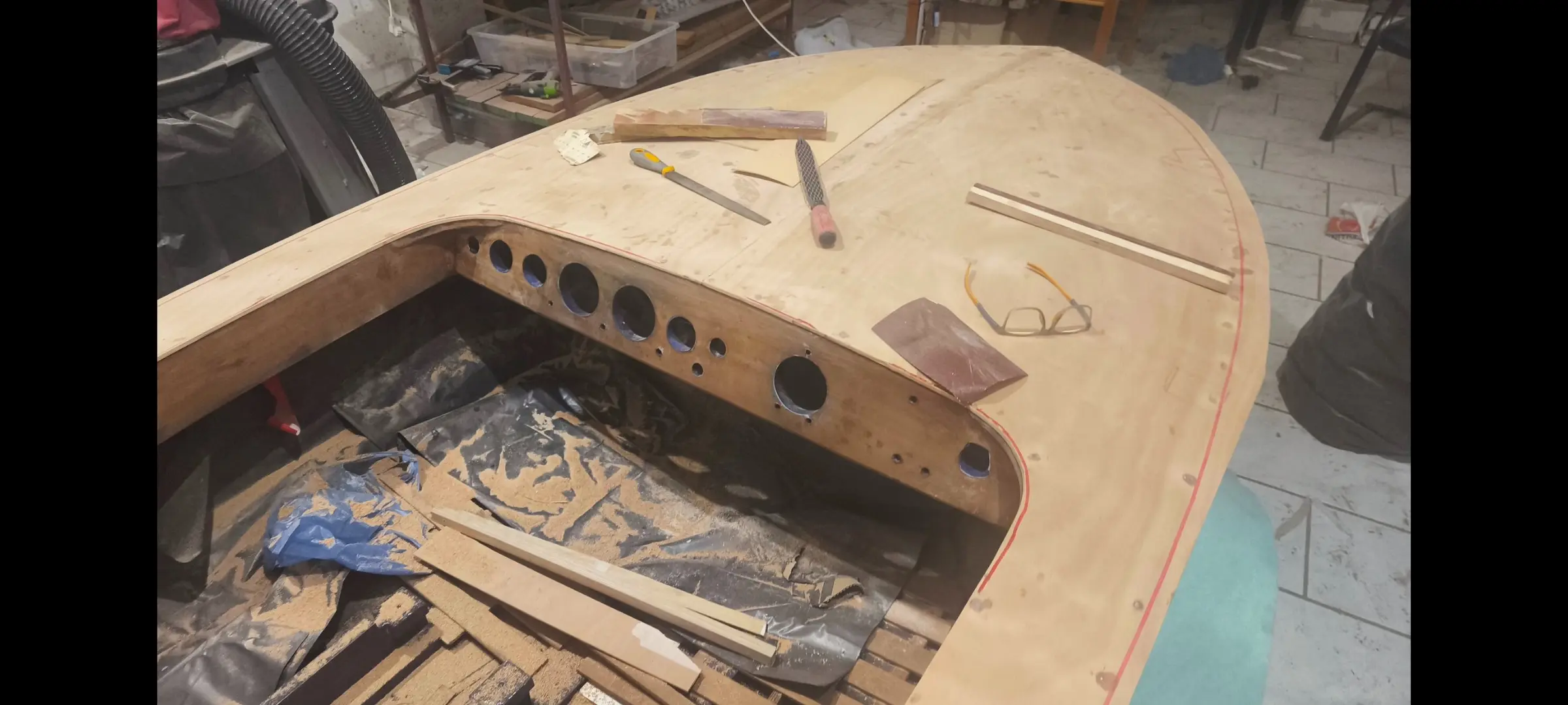
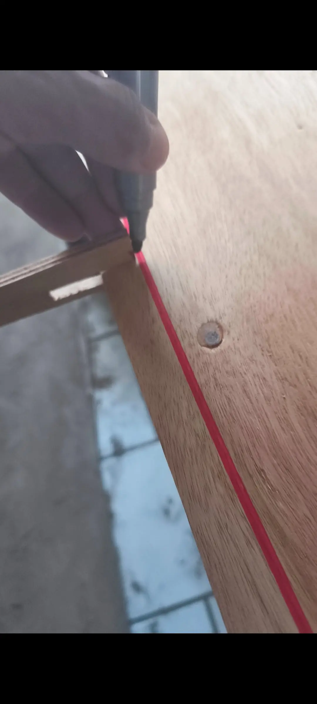
With the tool I made I marked the outline of the boat all the way round, with completely the wrong marker pen because the tip was too thick. It will be marked properly when the tool for the inside edge of the perimeter timber is made. At the aft end I used the curve the deck has at its end.

At the same time the inner floor was prepared, so we are not standing on the hull.


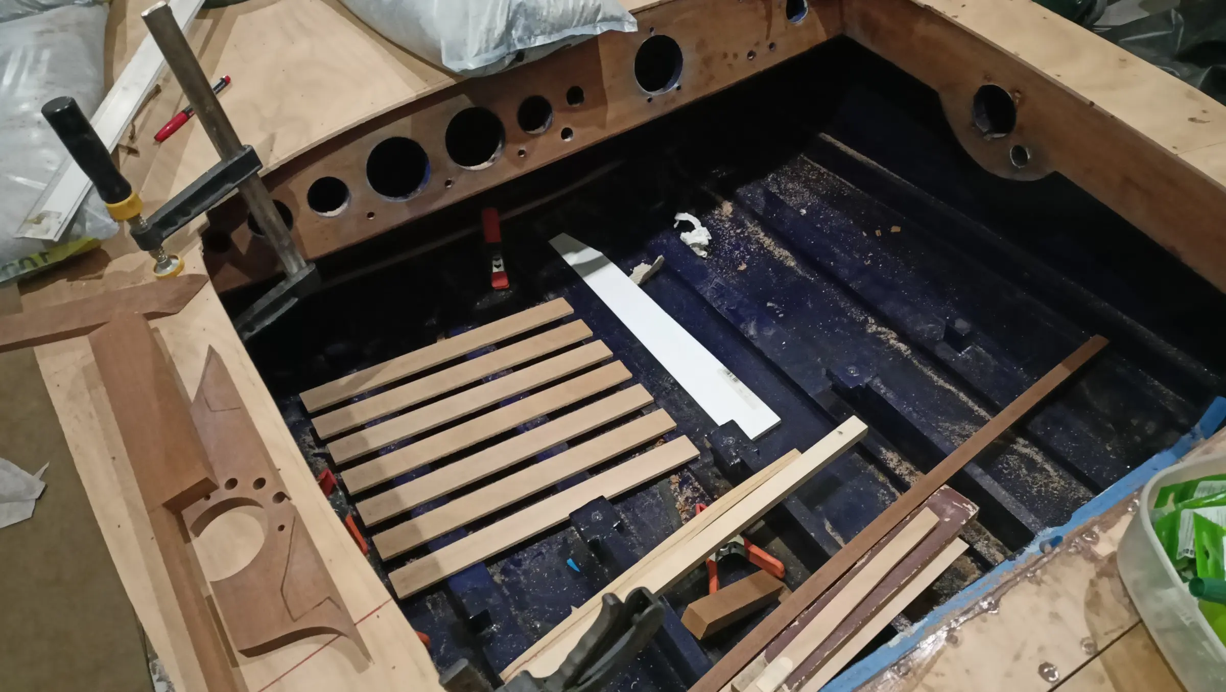
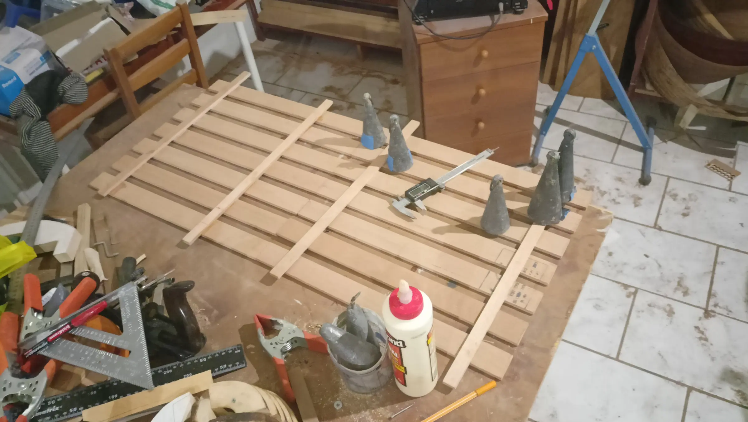
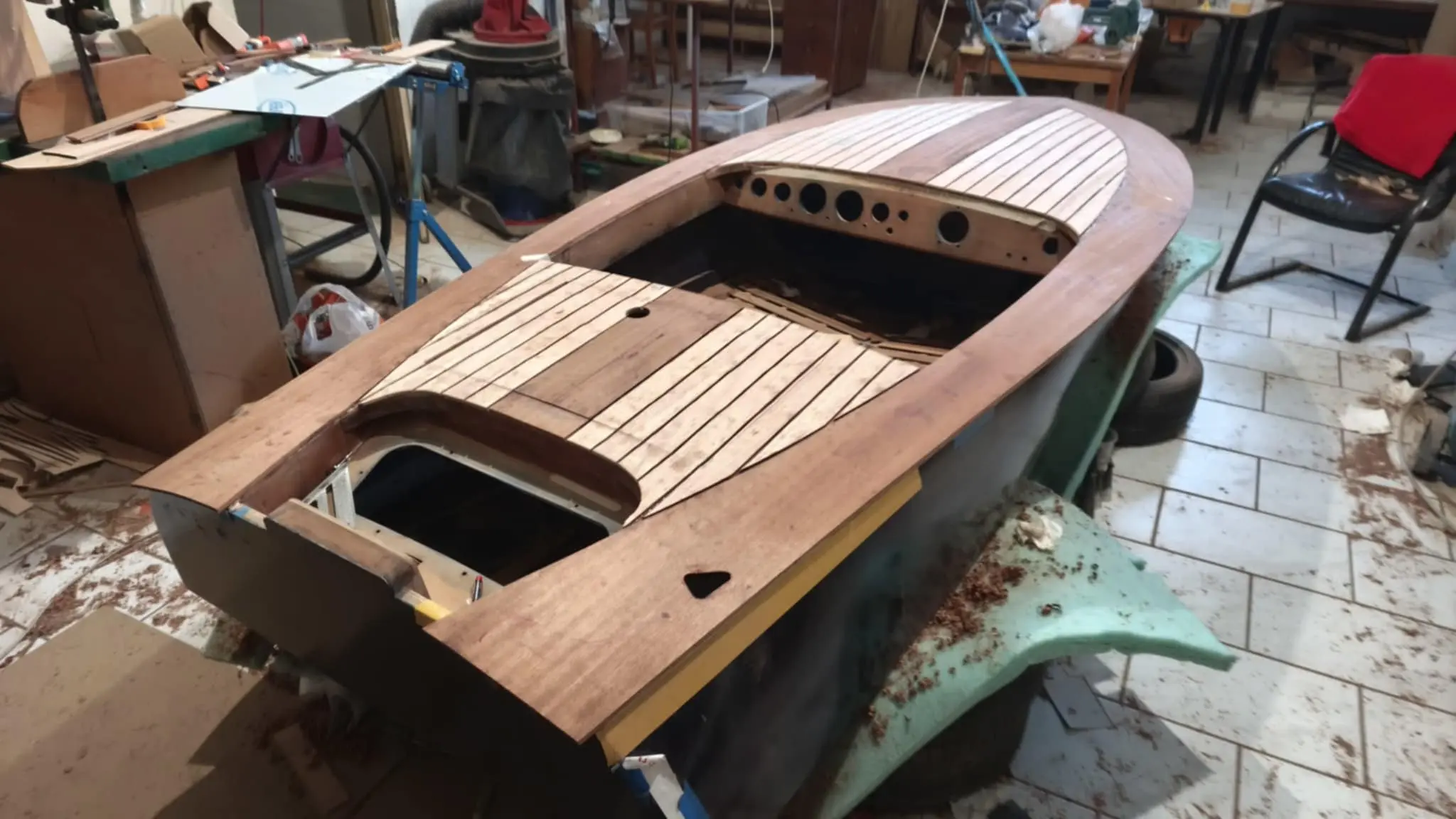
Laying the final mahogany deck

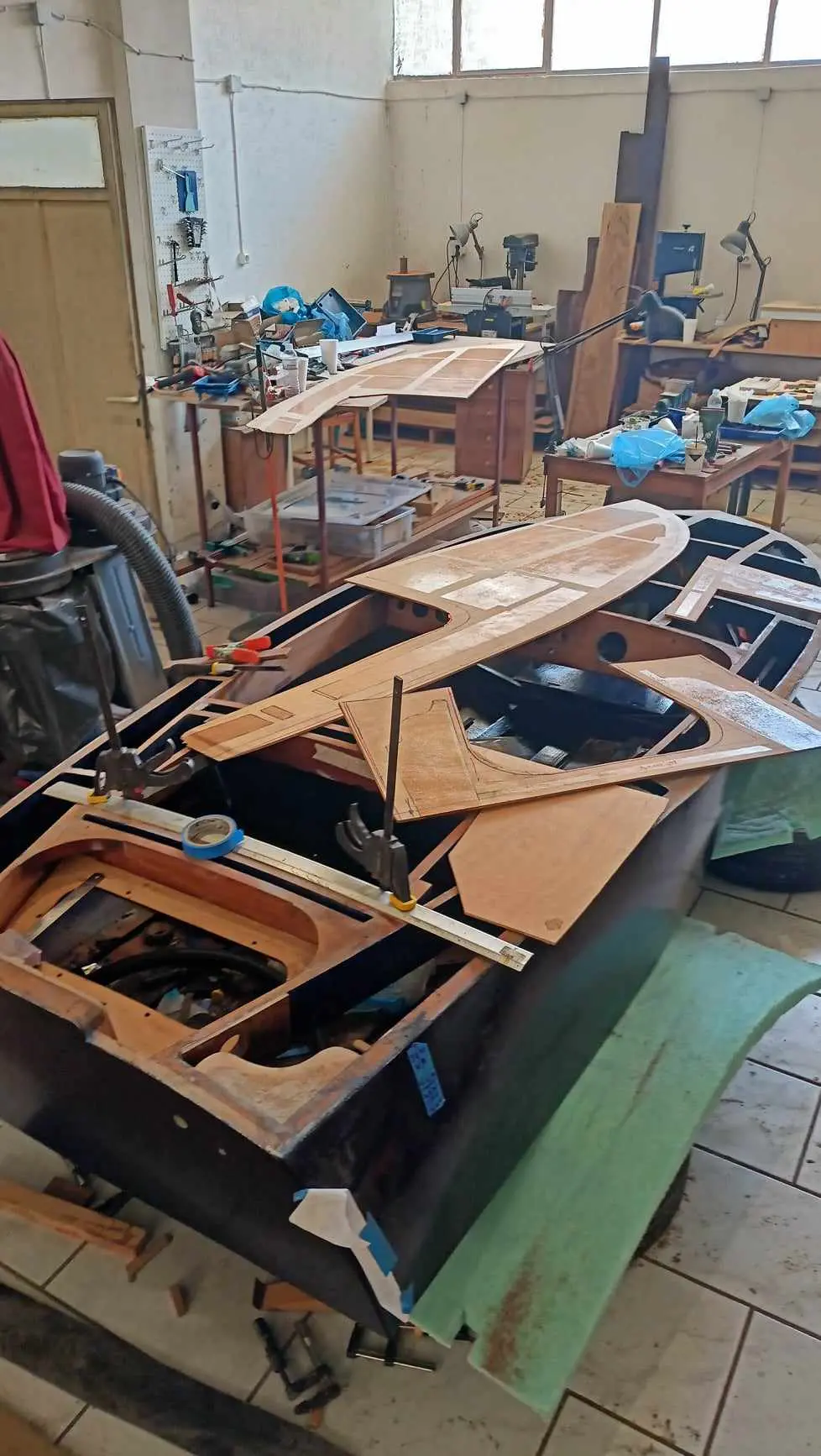
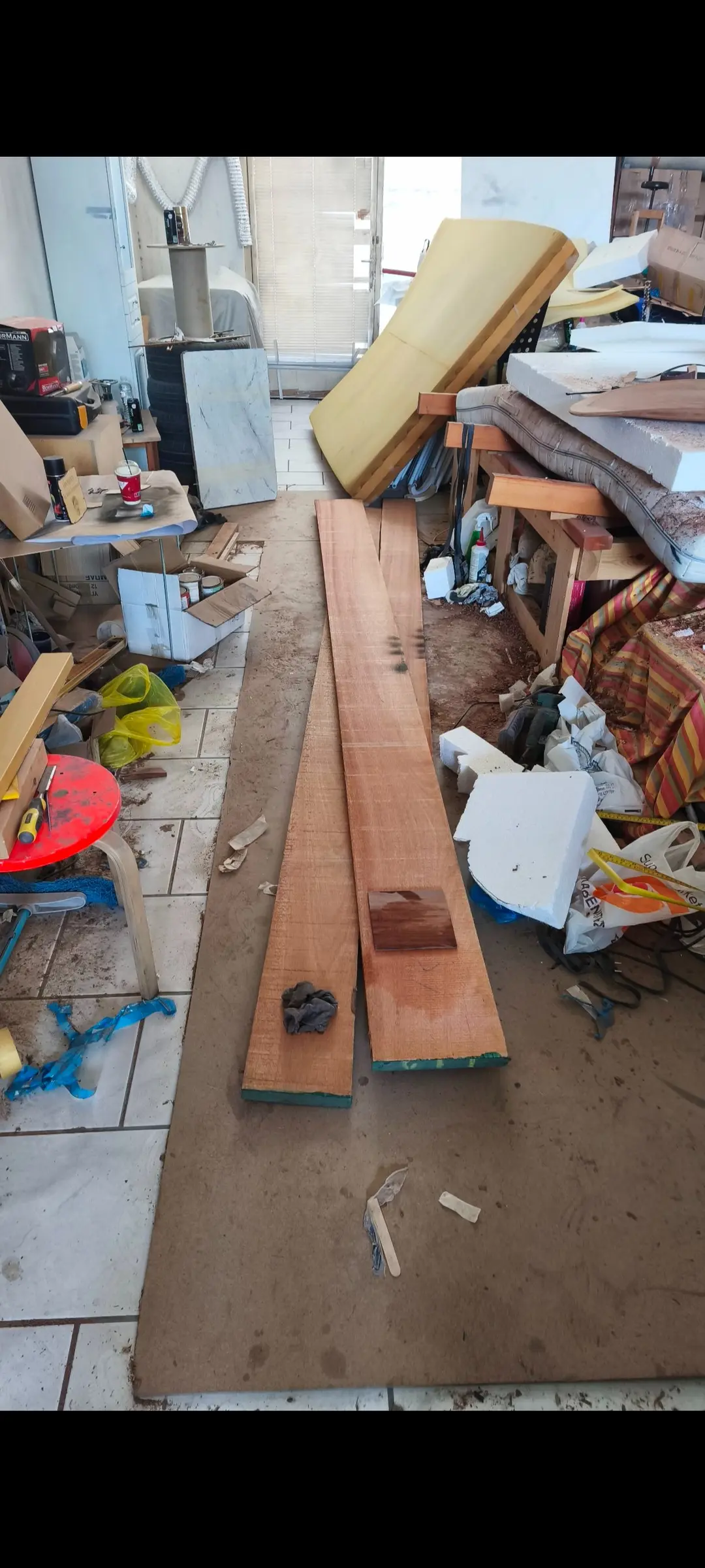
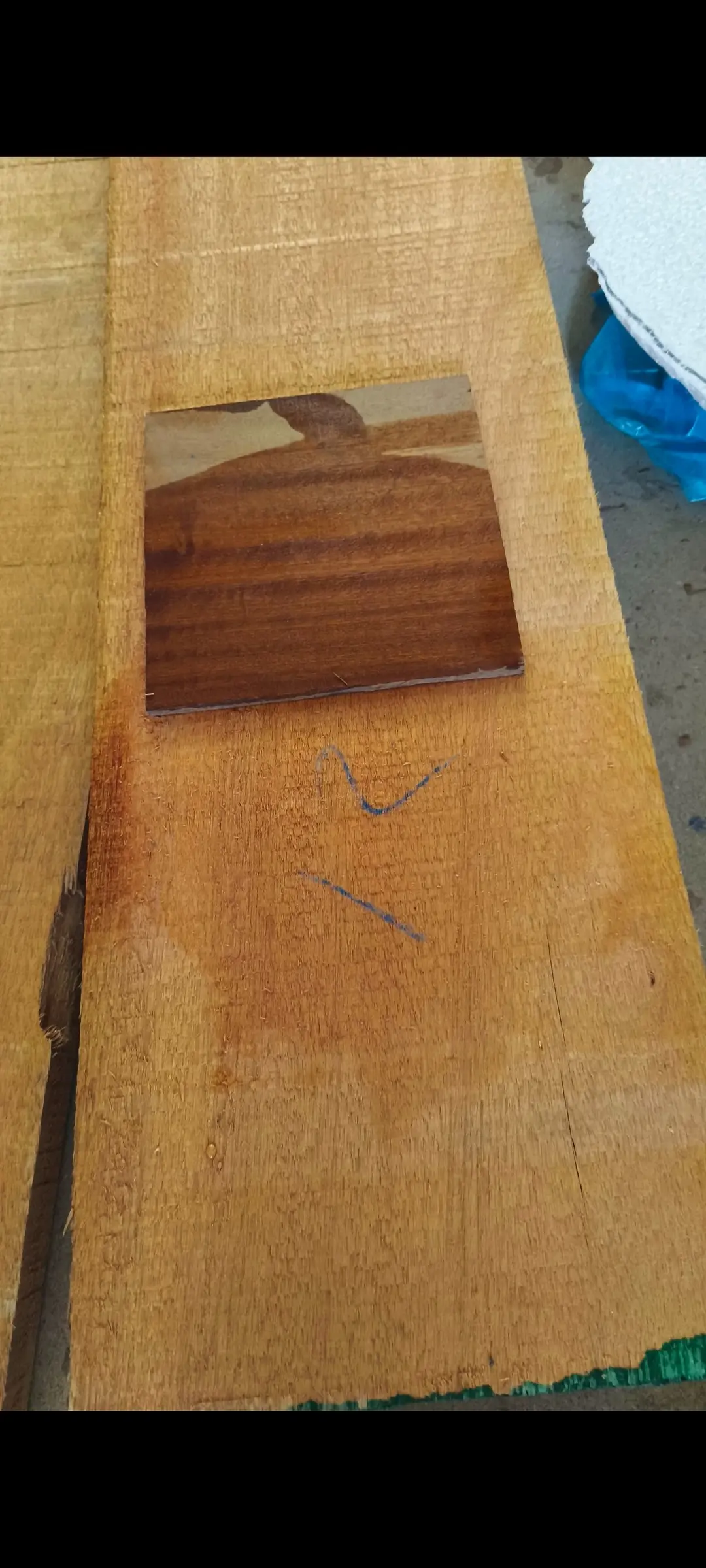
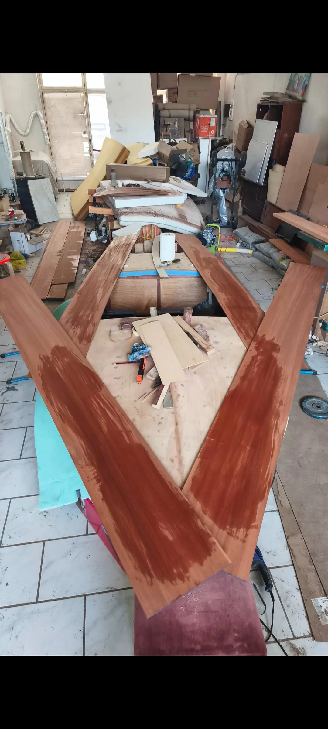
I bought the timber for the inner part of the deck. I found a very light coloured natural mahogany. The outer part of the deck will be made from a single sipo board 30 cm wide, so that a lot of pieces do not have to be glued up (see the photographs below). Because of the width I could not cut it on my own bandsaw, so it went to a boatyard to be cut.

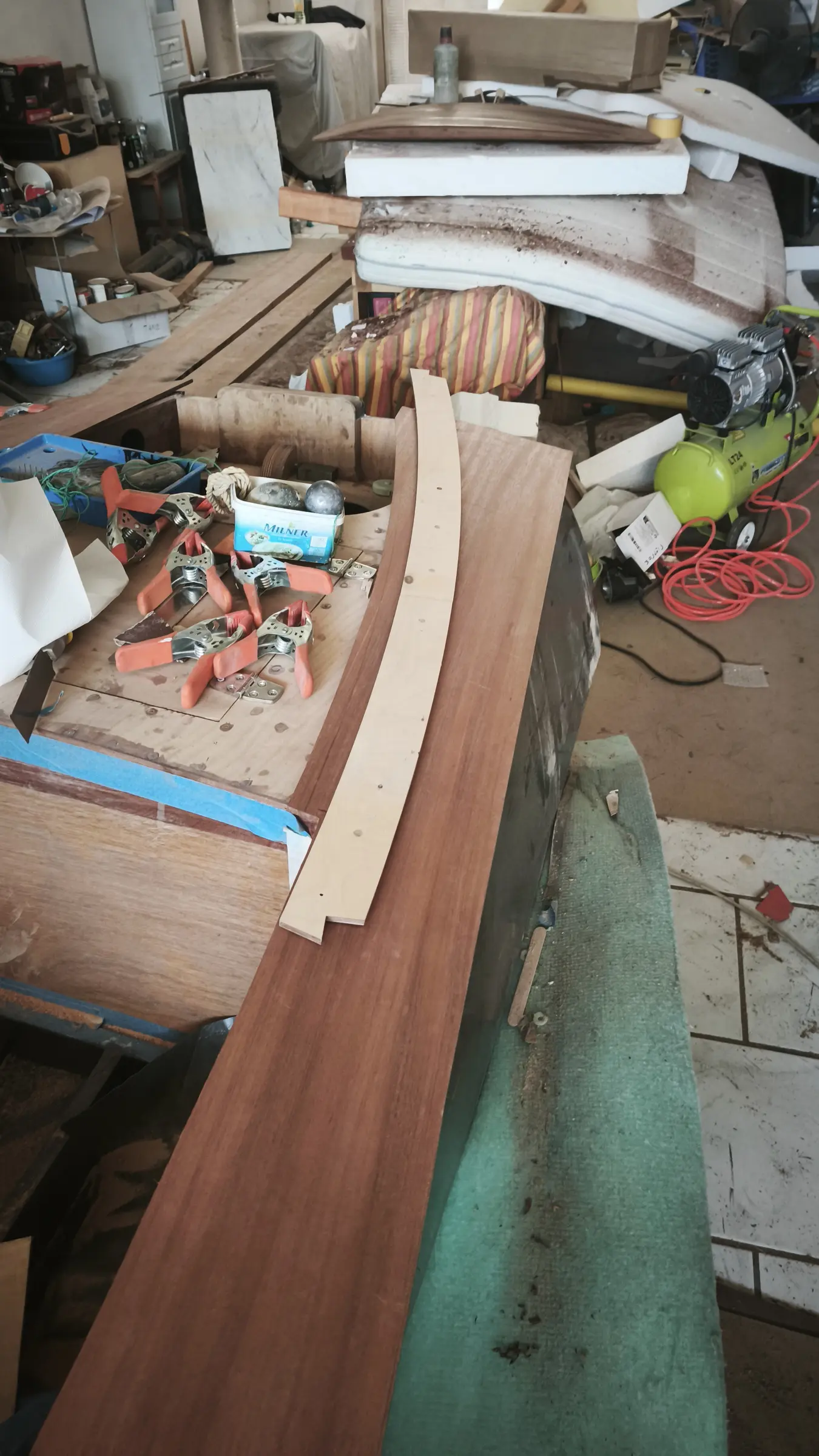
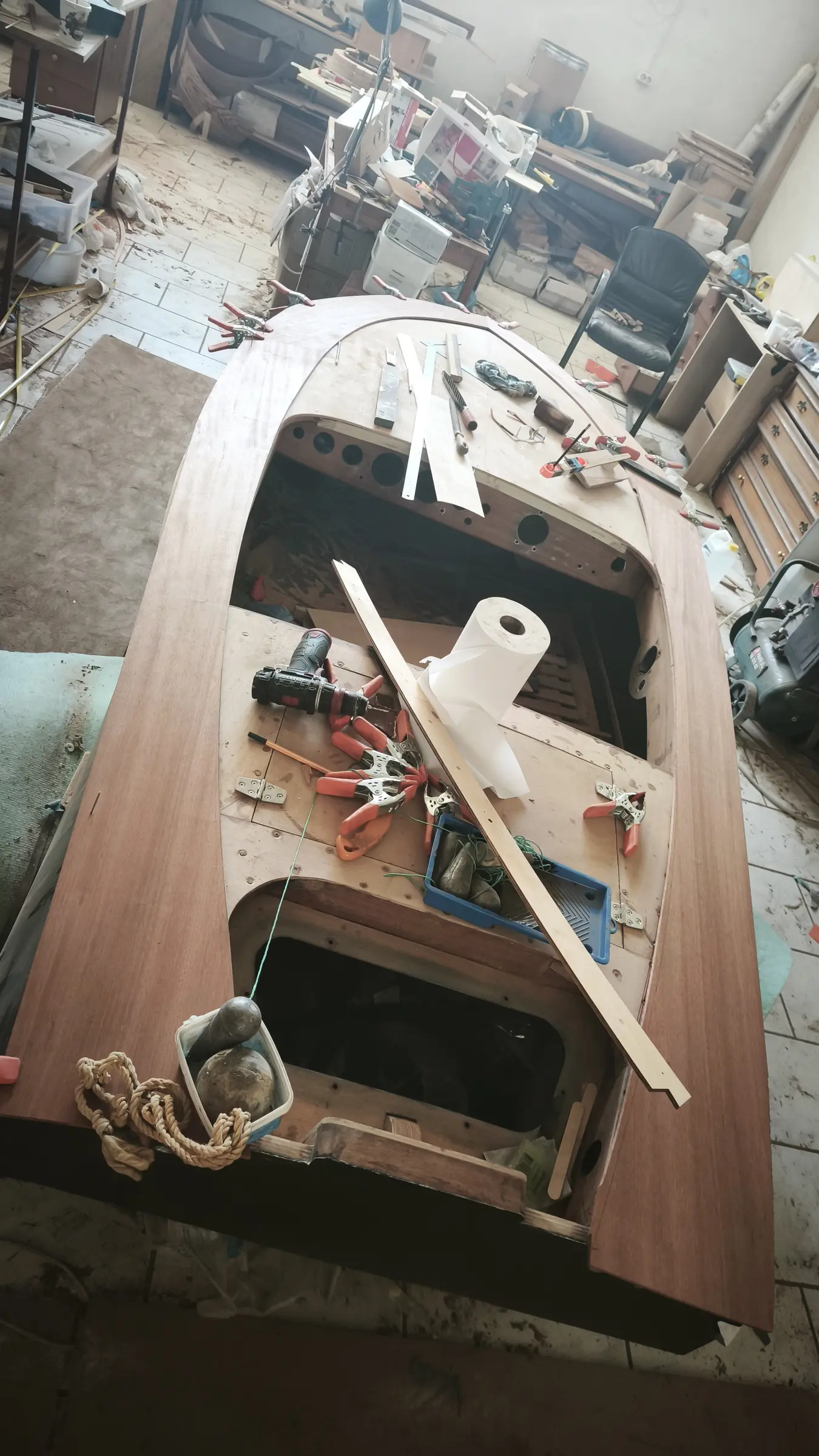
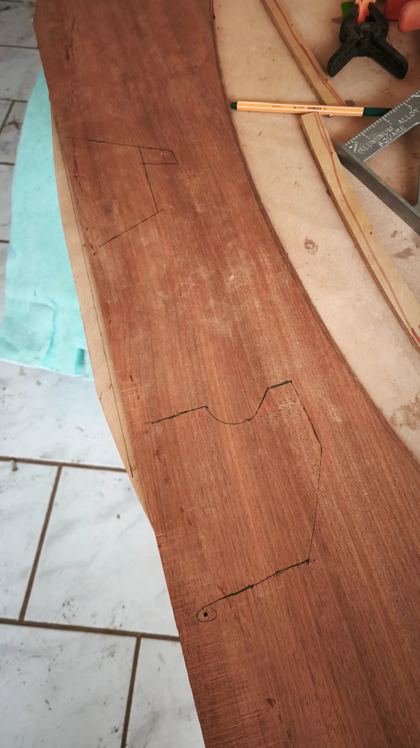
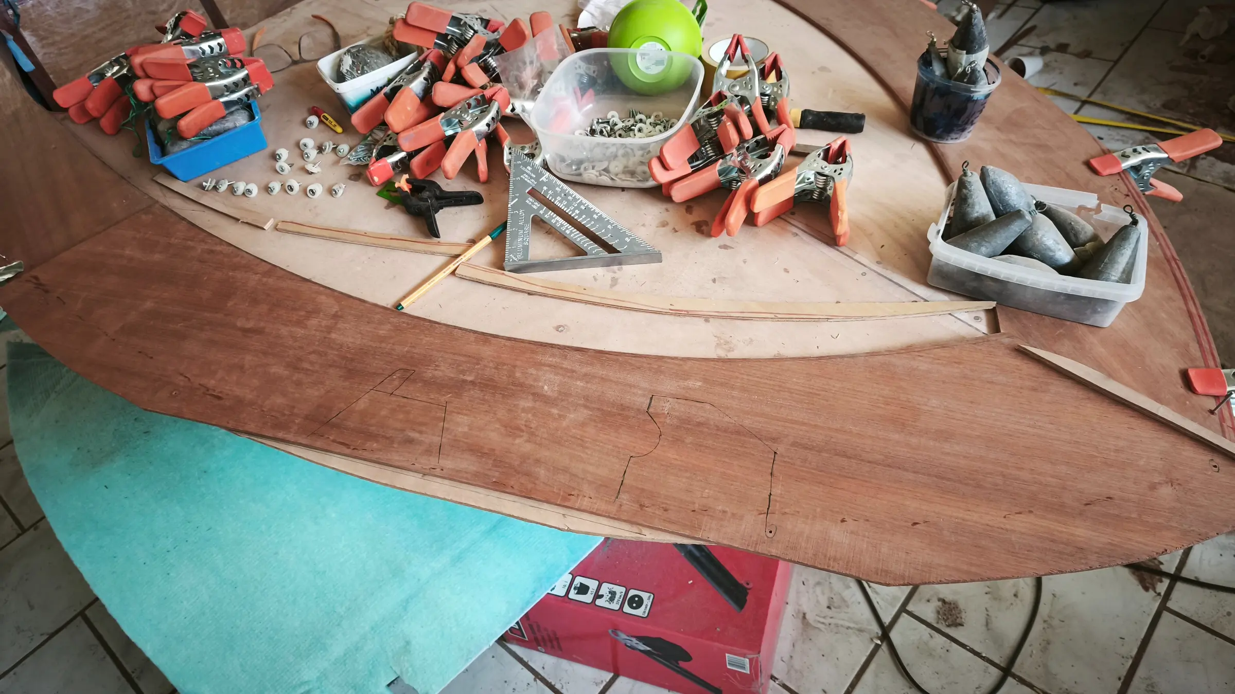
They were cut to the right shape (as far as the inner curve goes) with a great many measurements. I must have offered it up in position more than 20 times, as I have no more timber if I ruin it...

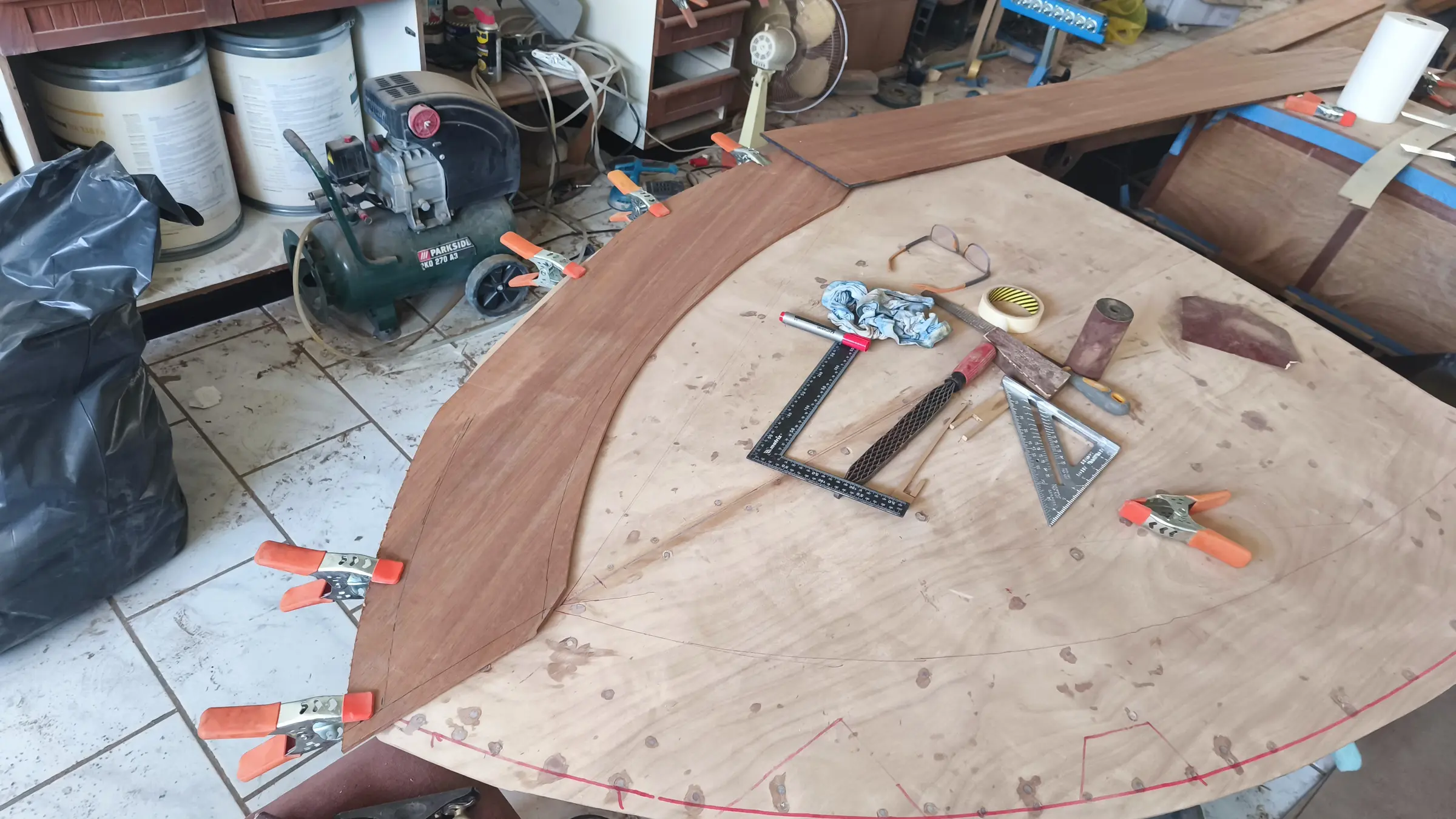
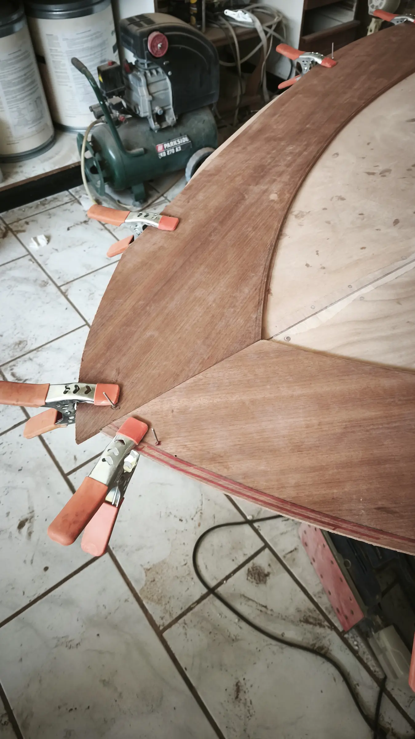
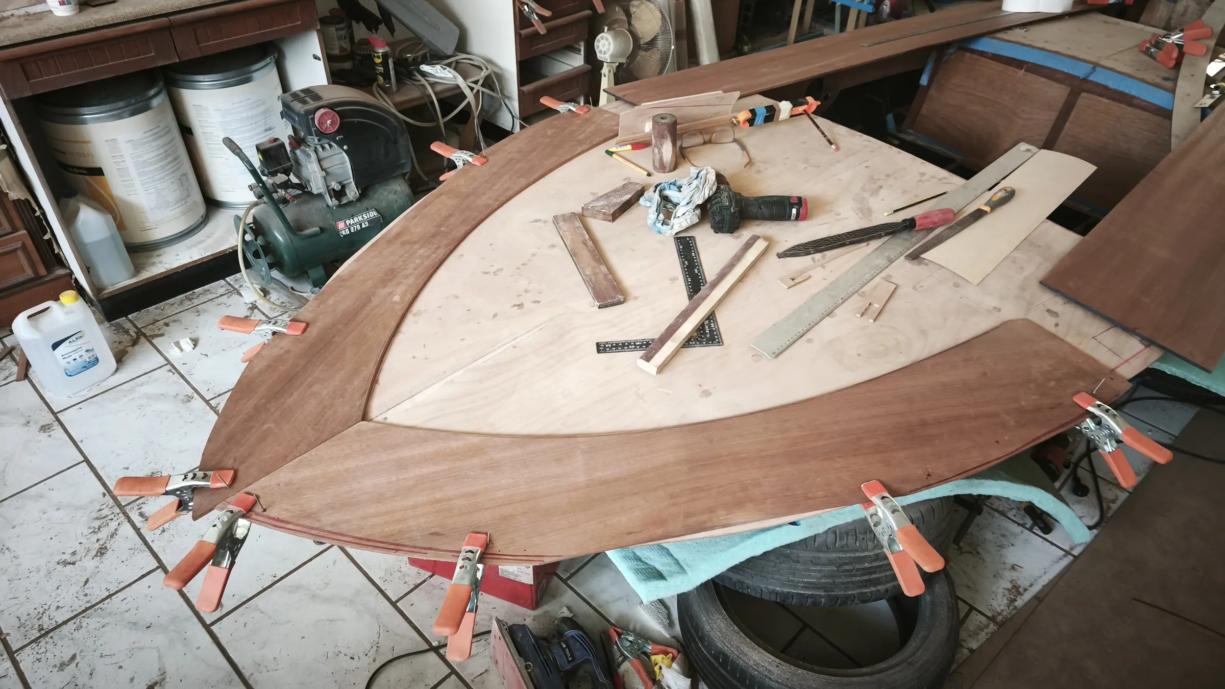
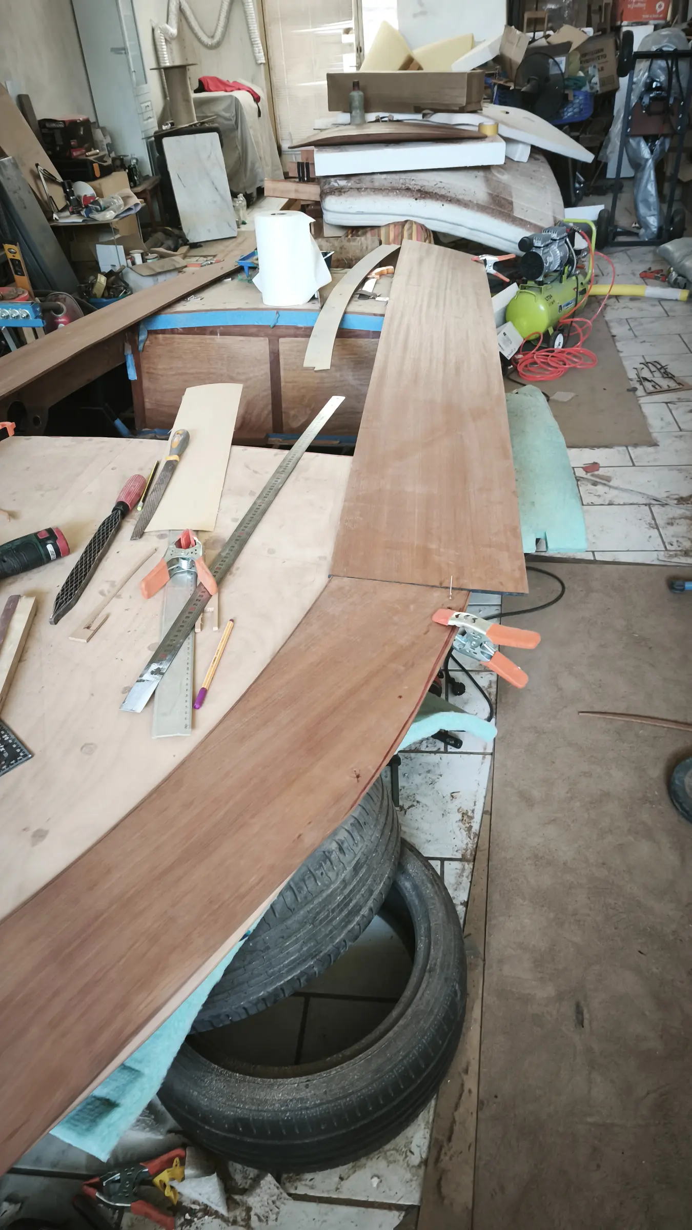
To get it in the right place each time, I put drill bits into 3 or 4 points, which hold it where it should be against the plywood underneath. The work is 95% complete, let us say, with the final cuts to be made when the forward pieces are glued.

Before gluing it I drew onto the timber the positions of the reinforcements underneath, for the stainless fittings to go into.

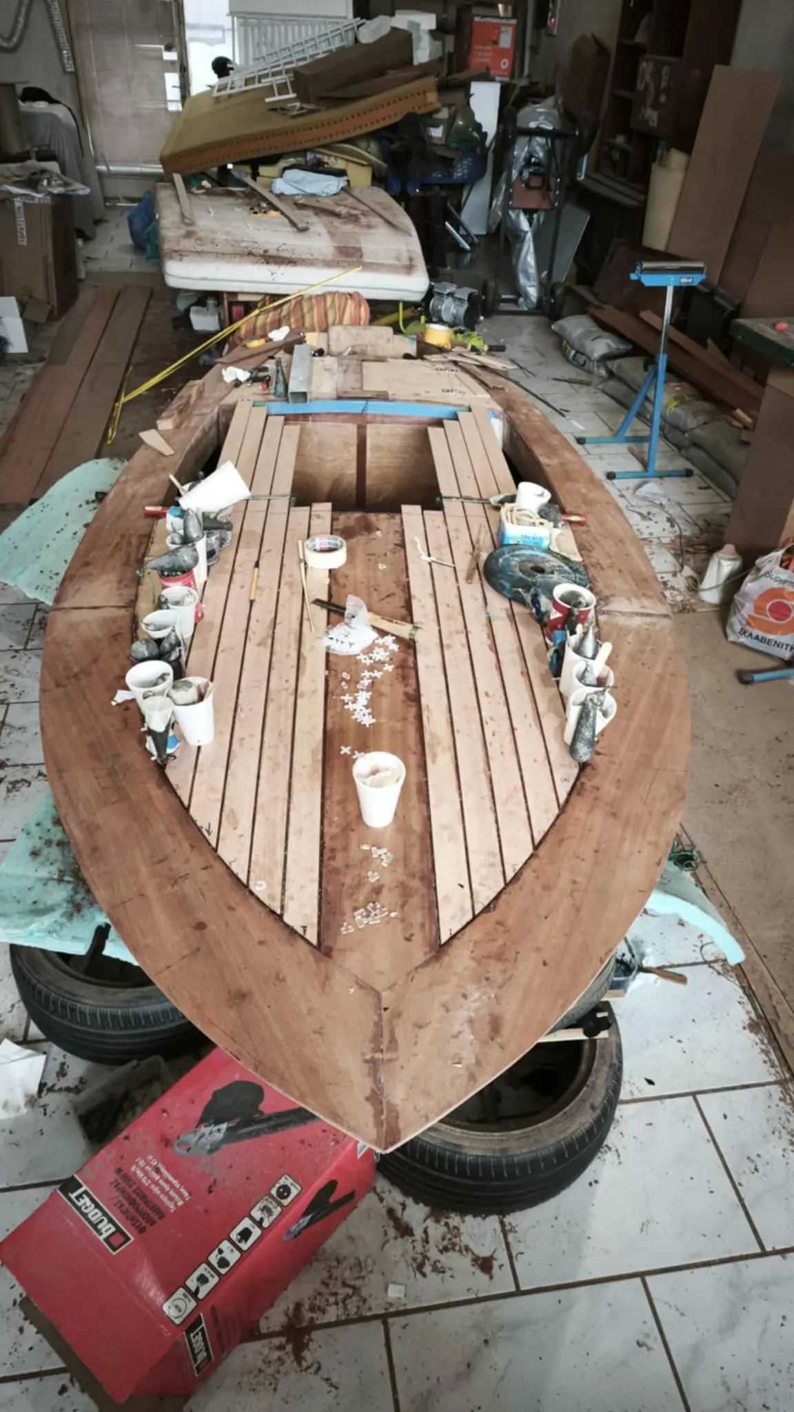
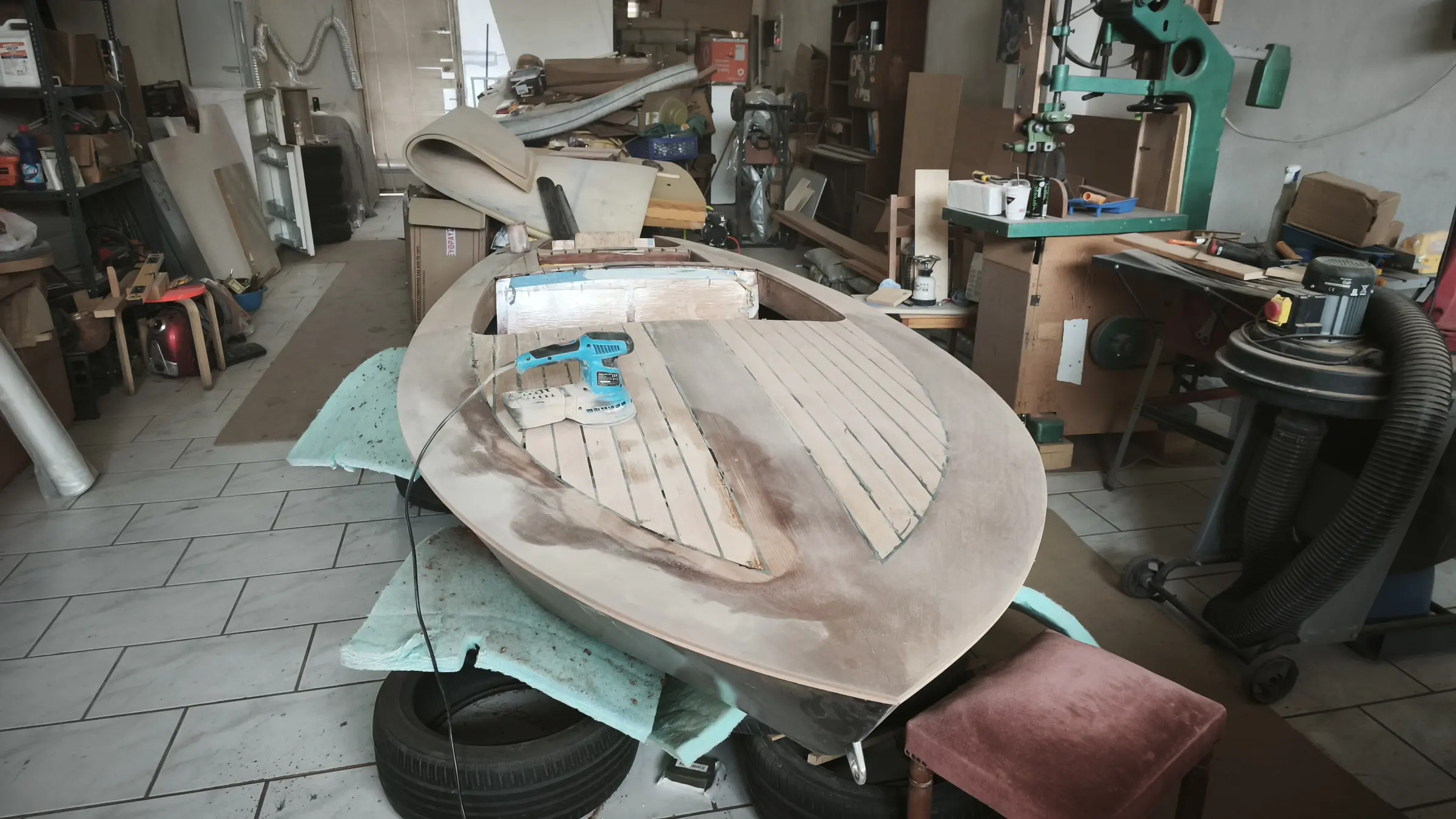
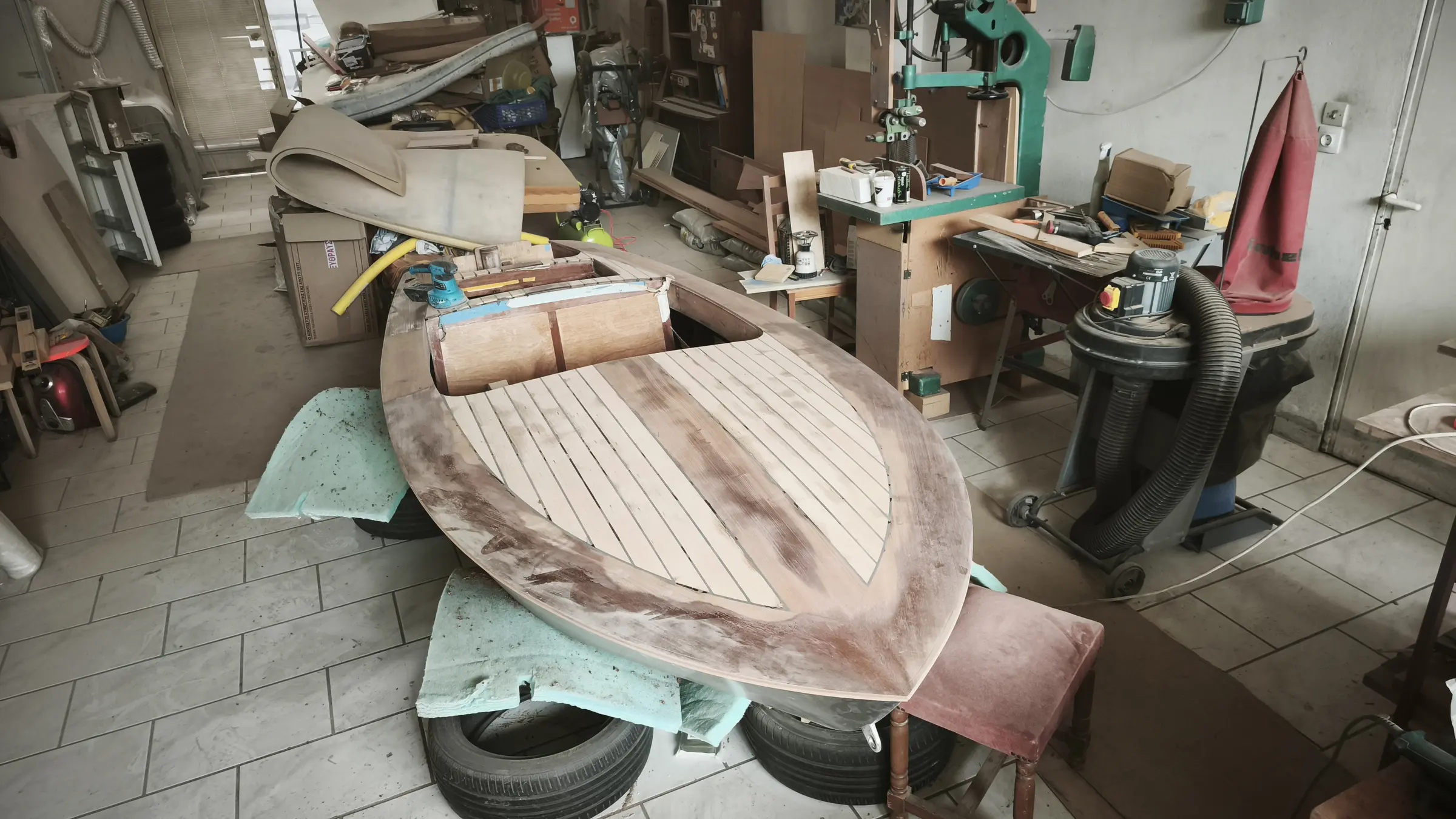
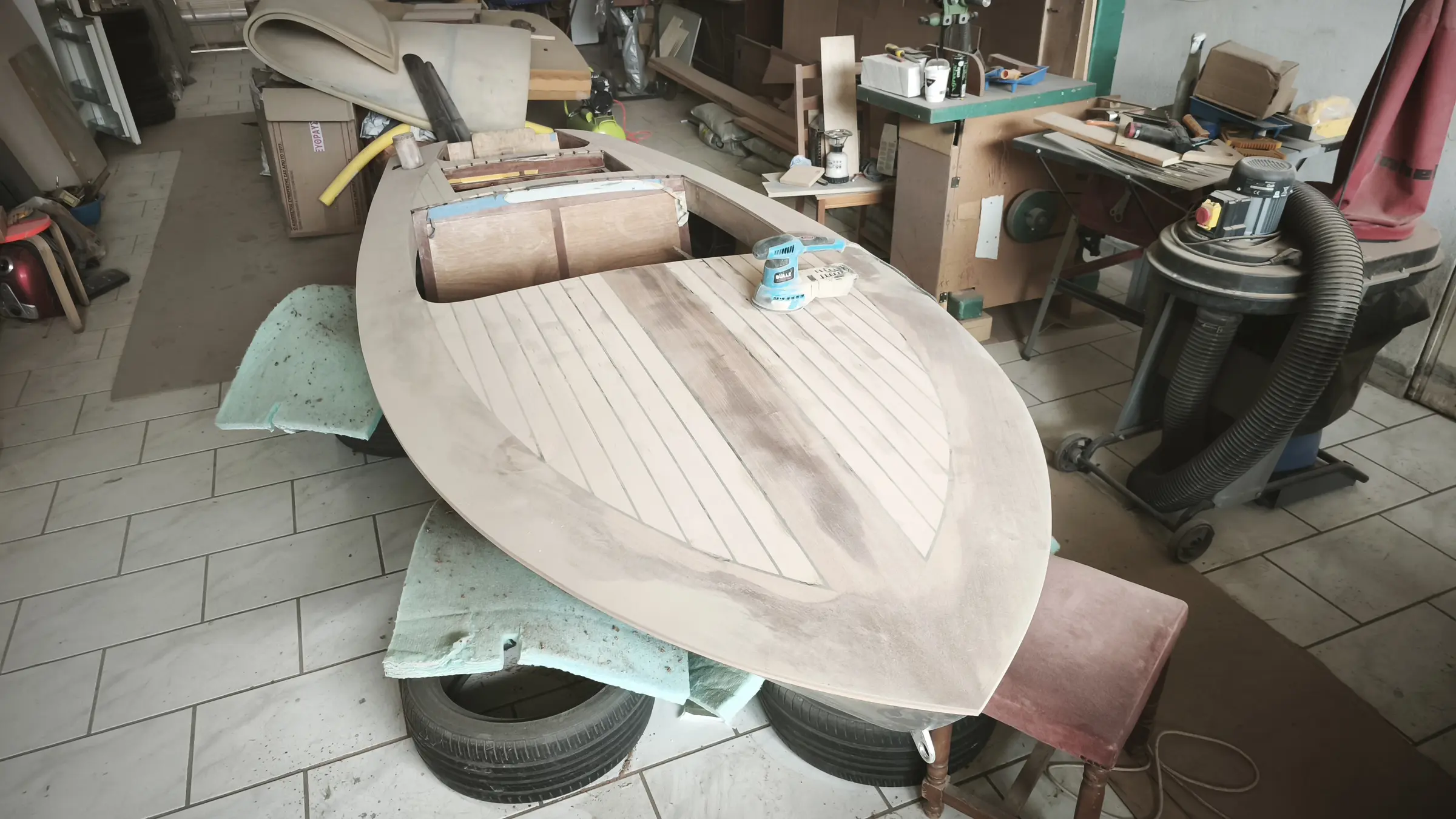
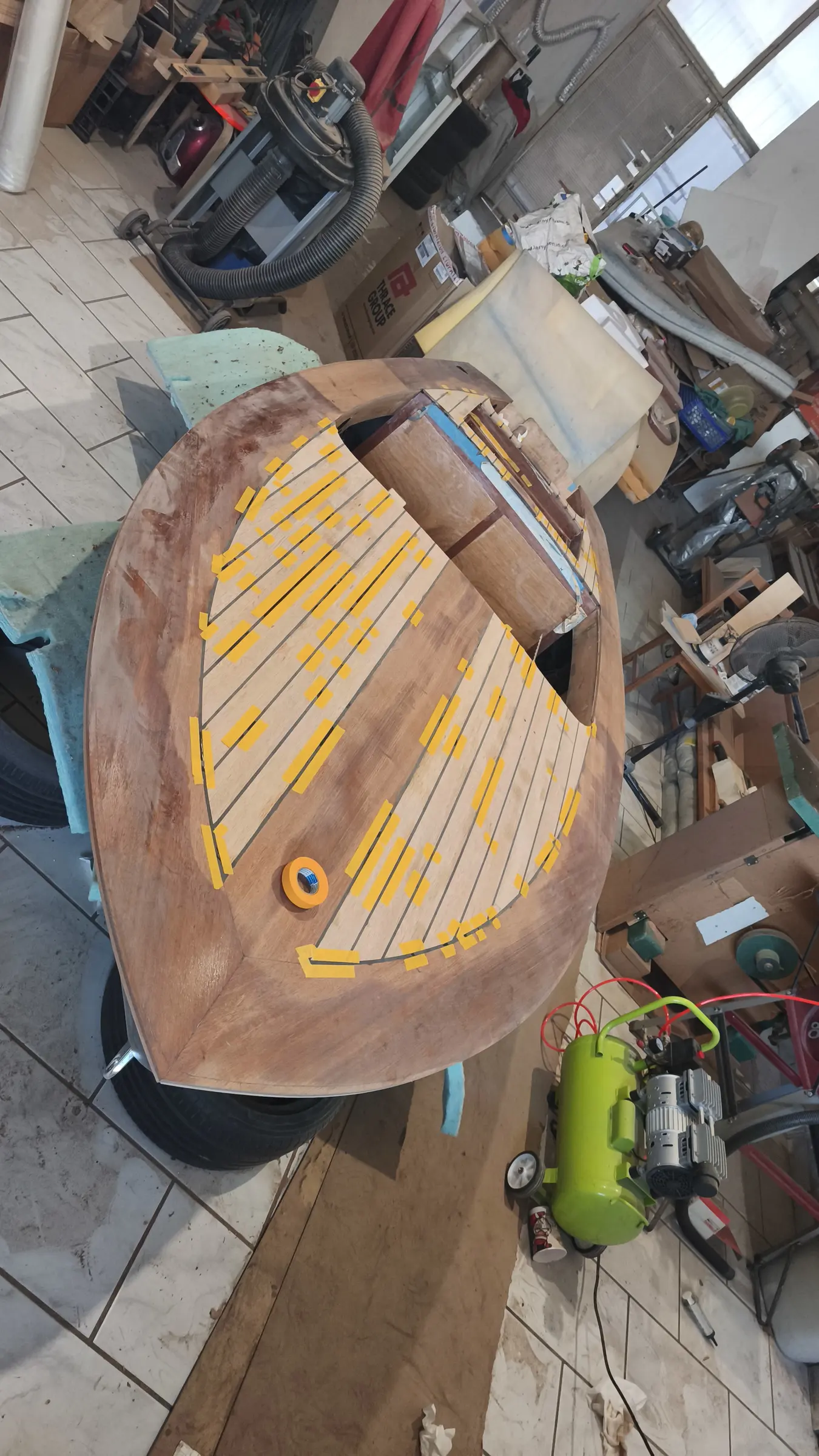
The first piece was glued.

To press the timber down onto the plywood on the outside I used my clothes pegs. On the inside, screws with a washer that presses the timber down.

Then the rest of the large perimeter and central pieces were glued.

The hole was drilled for the control cable.

Then the central pieces were glued in the locker area. As well as the locker, timber had to be glued forward and aft of it. See the arrangement in the photographs below.

To glue the two small pieces in line I used guides. Having measured and found the right positions, I put guides either side so the pieces could not move. Once I had them clamped I took the guides off so they would not stick in the resin that squeezed out.

The two small pieces forward and aft of the locker were glued first. I want to think first about exactly how the various stainless fittings for the locker will go in (the catch and so on) and then glue them.

A photograph of the finished result after gluing all the sipo pieces except the locker.

Once they were glued I checked the deck for symmetry at the two widest points that are created for the parallel strips that will go in. The result is more than good.

I did not have the thin strips cut and ready, so I went on to shaping the outside of the deck. I left about a centimetre of margin for the final work. I had not yet decided how the plywood and the timber would be shaped in section. See what I mean in the photographs below.

In the end I decided the cut would be vertical so I can fit a stainless rubbing strip. I also decided not to cut it flush with the hull but to leave a little timber overhanging, so that if it gets knocked against a quay at some point I have some margin to reshape it, taking a little more off.

I started with the saw to take off the bulk and carried on with a plane.

Work started on the thin strips.

I decided to use 8 thin strips at the forward end. Aft it comes out at 7. The width was worked out like this. I want the outer strip to be the same width at its end as the others, so it looks right. With 8 strips I will have 9 gaps to be filled with 5 mm of epoxy. So 43 minus 9 x 0.5 = 38.5.

38.5 divided by 8 = 4.81 cm. The piece opposite, which is 2 mm narrower, will effectively be made with strips of the same width. The two millimetres will be spread evenly across the 6 inner strips.

Aft, that width fits perfectly, as you will see in the photographs. If it had not fitted I had decided to reduce the width of the outer strip a little.

The timber was cut. The pieces were laid on the boat to match them for colour between left and right. Each piece was cut into 3. The first two from each were placed one left and one right (bookmatched). In the end that is not really necessary, as they are all the same colour and do not have much figure.

Alongside the forward end, gluing started on the central pieces at the locker. For gluing I first used the guide to hold the line, but the timber was not bedding well even though I had put weights on top. So I used clamps, being careful the timber did not kick out.

Each time, one strip of timber is glued on the left and one on the right.

The forward end is almost finished. Aft, because of the locker, more pieces have to be glued in smaller sizes.

Some photographs of the gluing in the middle section.

Then all the locker pieces were glued and the hole was cut for the handle. The handle needs a good deal more work from underneath to fix it properly with screws.

Some photographs of the boat with the timber all glued on. It has not been shaped yet.


Gluing mahogany onto the aft locker

I decided to glue only the dark mahogany onto the aft locker. To take the measurements for the pieces, and because the various pieces glued to each other are not square, I laid on thin sticks of the same thickness as the timber to be glued and then stuck paper between them to build up the shape I wanted.

The finished result is shown in the photographs below. Small holes were drilled in the transom to let water out, and the recess shown was made on the inside. A slope had been allowed for in the plywood so that water is led to the two corners.

The inner part of the locker was finished too. It has not been fully sanded yet. The stainless fitting that will hold it has been designed and will be sent for laser cutting.


Black G/flex resin seams

The next job is filling the gaps between the thin strips.

And this is where the headache started...

We had the following options:

  1. Fill with West System 105-206 epoxy resin with pigment.

  2. Fill with strips of wood.

  3. Fill with a solid plastic.

  4. Fill with a special sealant (Sikaflex, for example).

  5. Fill with a flexible epoxy with pigment.

The first 4 options all have their problems.

I spoke to a wooden boatbuilder who also works with resins, and to a lot of people on American forums.

  1. The resin will be rigid while the timber is flexible. With expansion and contraction the timber could split or distort. The positive is that the resin and the varnish will have no problem over it.

  2. Wood strips will have almost the same stiffness and will follow the expansion and contraction of the other timber. Probably more difficult, because I would have to cut them and shape them at the joints. Resin and varnish would go on without a problem here too. The problem is that it would be harder to get them black, which is what I had in mind. I have two options. Either the dark mahogany, which would probably look nice apart from where it meets the dark strip (the first gap and the perimeter would have to be black), or all black. I still have no idea what pigment to use, or how, so that it does not run into the strips either side.

  3. The boatbuilder I spoke to told me he had used PTFE in one of his builds in the past and it worked well. PTFE is very heavy though and does not bond well with resin. He says it needs special treatment to bond properly. I read that PVC bonds very well (perhaps that is what he meant). The positive is that they are flexible and will follow expansion and contraction. I do not know how it will work with resin over the top. I would have to do some tests. Probably resin should not go over it.

  4. Exactly the same as 3 for the special sealants. What is recommended is that it goes on after the resin. It definitely needs testing.

  5. There is a special resin that is flexible. It is called G/flex, it is West System, and it is of course extremely expensive. With that I have no issues with expansion and contraction and I can put resin over the top of it. And pigment in it too, of course.

That is the way I went.

Five millimetres wide and seven deep. Whatever material I used, I would have waterproofed with plain resin. Even if I had used the flexible ones.

And now, with the flexible resin, what I did was put on two coats of the ordinary resin I use with a brush (West System 105-206). And so the wood would not soak up the expensive resin and I would need more of it (it is sold by the kilo and I was worried I would need a second one, as I am probably marginal).

First the boat was cleaned with lukewarm water, soap and a Scotch-Brite pad to remove the amine blush.

Then it dried and was sanded. Having cleaned it again I wiped it with acetone so it was ready for the G/flex.

The boat was masked up so it would not get dirty, although it will be sanded anyway to remove the 106 resin I have put on for protection. At one point I got fed up and did not mask, and it went black very easily...

The G/flex mix I used was 60 ml of resin, 60 ml of hardener, 4 g of West System black pigment and 60 ml of glass bubbles.

In tests I did on the proportions I saw at first that I could have used three times as much glass bubbles and made the mix much lighter and much thicker.

The resin on its own is like honey. With the 60 ml it got thicker still but stayed liquid. It only just dripped off the stick.

With three times the amount, which I tested, it went like peanut butter. I liked the result, but I read that at high temperatures it might let me down in future.

Both in the test and in the application on the boat, the resin went into a piping bag.

I made up that mix 5 times (5 x 60 + 10 ml from the test = 310 ml out of the 500 ml in each tin).

What I found is that the resin shrank a little and needed a second coat, which it got. Where the timber ends I used masking tape to hold it in. That definitely needs a lot of work and perhaps I should have made it a bit thicker.

The worst thing I have done so far. Five hours bent over, ready for physiotherapy. And 5 hours squeezing the piping bag, I could not feel my fingers.

A mask is essential when mixing, as the glass bubbles are the lightest and finest material there is. The moment you touch it, it clouds the air. Long-sightedness and a mask do not go together very well.

Some photographs of the process.

A third coat in certain places.

Then I decided to sand the deck to see what result I had. I saw that in places it needs another coat of resin (a fourth). I will sand again at the end, as there will be plenty of other places needing sanding.

The bill

What it cost

Everything else
Timber for the building base €120.00
Glen-L Squirt plans 1 €78.00
Screws and nails €183.23
Plexiglass template stock, laser cut 1 €43.00
Plywood for the frames and transom 2 x 7 mm, 1 x 20 mm €160.00
Sapele for the frames 3 €150.00
Screws for the building base €12.00
Epoxy resin 5 litres €222.00
Microfibre filler 10 lt €14.67
Fiberglass cloth 20 €44.00
More marine plywood 4 x 6 mm €236.00
Rollers and sundries €35.00
Brushes €14.00
Silicon bronze screws from England, No. 2 €50.00
Galvanised carriage bolts €10.00
Tools: router, sockets, drill bit €110.00
Disposable gloves €10.00
Packaging bags for steam bending €15.00
Steamer €70.00
Alignment laser €22.00
Forward mooring cleat 1 €15.00
Aluminium angle for the table saw €13.00
Scales €6.00
9.5 mm drill bit for the cleat €5.00
Forward mooring cleat €14.00
Microballoons €9.70
Speedometer €80.00
Battery gauge €40.00
Horn and button €76.00
Spiral screwdriver €32.00
Aft mooring cleats 2 €22.00
Brushes and rollers €30.00
Cleats 2 €18.00
Sipo, 3350 x 170 x 65 0.037 m3 €80.00
Joiner's fee €150.00
Brushes 60 €37.00
Cable ties, 37 cm 1 pack €7.00
Spring clamps 70 €63.00
Sipo, 3350 x 140 x 65 0.03 m3 €60.00
Brushes 60 €19.00
Corrugated card 8 m €5.00
Stainless coffee cup holders 2 €7.50
Fuel gauge 1 €9.00
USB and 12 volt socket €6.00
Screws and plastic washers for planking 100 + 100 €7.00
Screws and plastic washers for planking 100 + 100 + 100 + 50 €15.00
Resin mixing sticks 100
Epoxy resin 5 litres €223.00
Epoxy primer 1 litre €56.15
Timber for the second building base €30.00
Fiberglass cloth, 213 g/m2 €123.70
Roller trays, 20 mm 2 €3.00
Epoxy fairing filler €24.00
West System resin rollers 8 €65.00
Resin rollers, 9 in 2 €18.00
Double-sided tape €1.00
Dowels, 10 mm €4.00
Chandlery: lights, switch, pumps €262.60
Yamaha 25 hp GES EFI outboard 1 €4,340.00
Flush-mount control box 6X3 1 €170.00
Epifanes Polygloss Britannia Blue 3 €135.75
Hempel epoxy filler 1 lt €68.50
Hempel light primer 0.75 lt €40.00
Thinner 0.75 lt €18.00
Brush 1 €6.50
Rollers 2 €6.40
Rollers 3 €7.50
Mixing pots 15 €10.00
Rollers 14 €8.00
Black brush 1 €5.00
Water containers 3 €19.50
Water container 1 €8.00
Box section for the outboard dolly 6 m €18.00
Dolly wheels, lower 2 €18.00
Dolly wheels, upper 2 €30.00
Machine shop, drilling the dolly axle €10.00
Locker catch 1 €35.00
SeaStar TFX N.F.B. 4.2 steering helm 1 €239.90
SeaStar SSC62 TFX Quick Connect steering cable, 16 ft 1 €133.00
SeaStar TFX NFB 90 degree bezel kit 1 €20.00
Osculati steering wheel 1 €132.00
Fairleads 2 €20.00
Locker catches, fore and aft 2 €14.00
Pump outlet fittings 2 €24.00
Brushes, 2 cm 40 €14.00
Forward deck cleat 1 €25.00
Fuel vent 1 €30.00
Silicon bronze screws from England, No. 3 €46.00
Push switches 6 €36.00
Cable tie bases for the wiring 20 €4.24
Horn button, No. 2 1 €7.00
Double-sided tape 1 €1.80
Total spent €8,936.64

boatbuildlog.com

Glen-L Squirt
26 entries, 861 photographs, written down as the work was done.

The words and photographs in this log belong to George.

The log itself lives at
https://boatbuildlog.com/builds/glen-l-squirt

Printed 9 September 2026