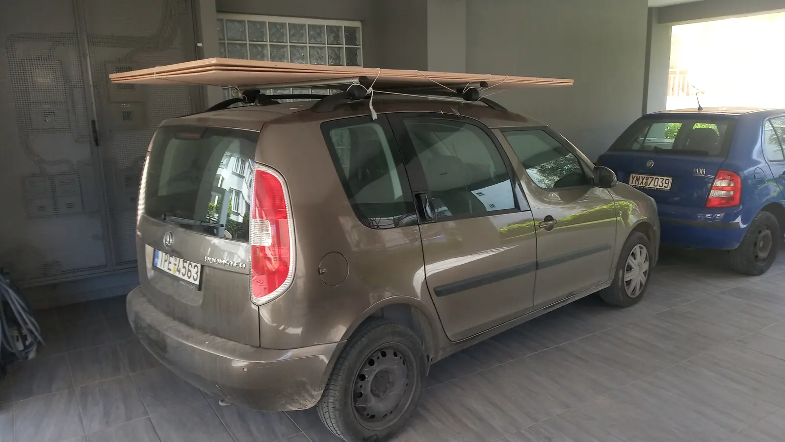
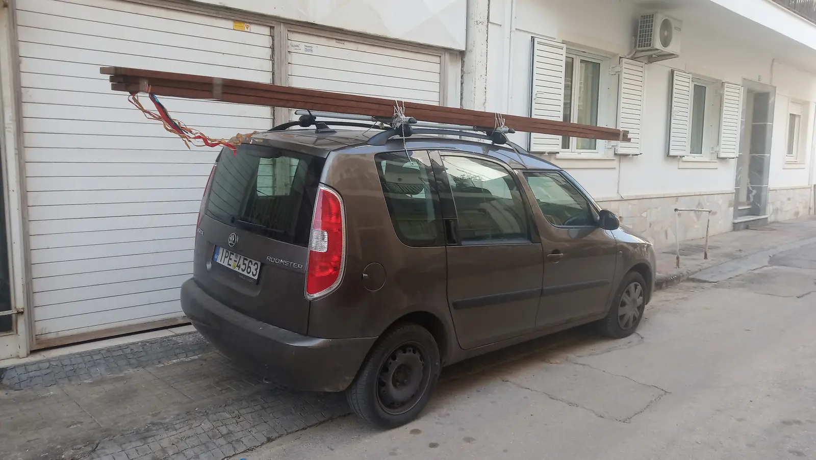
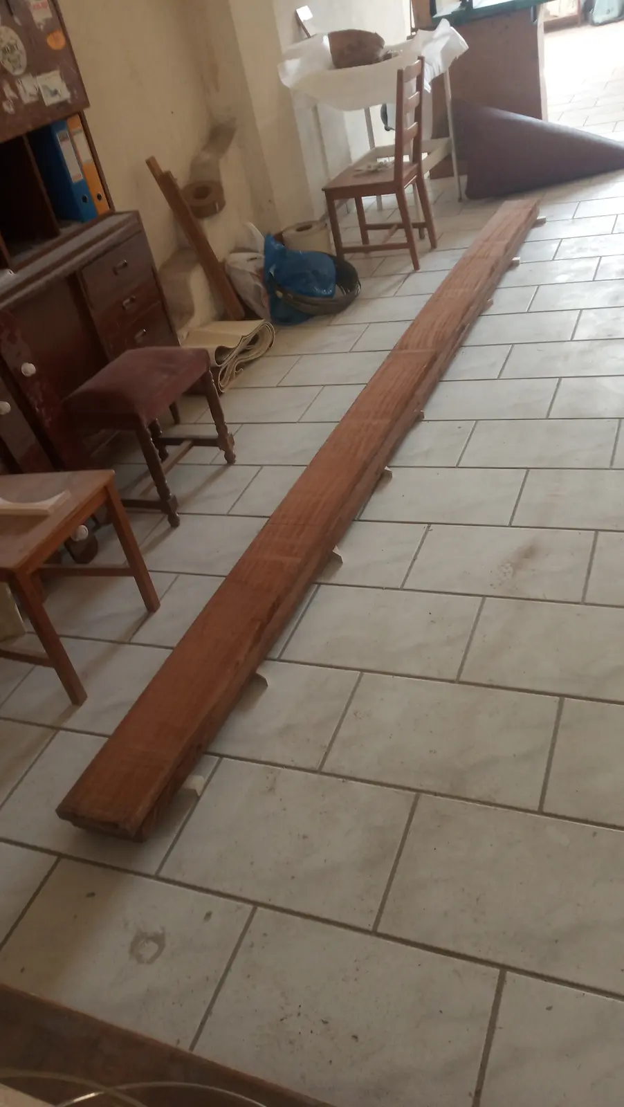
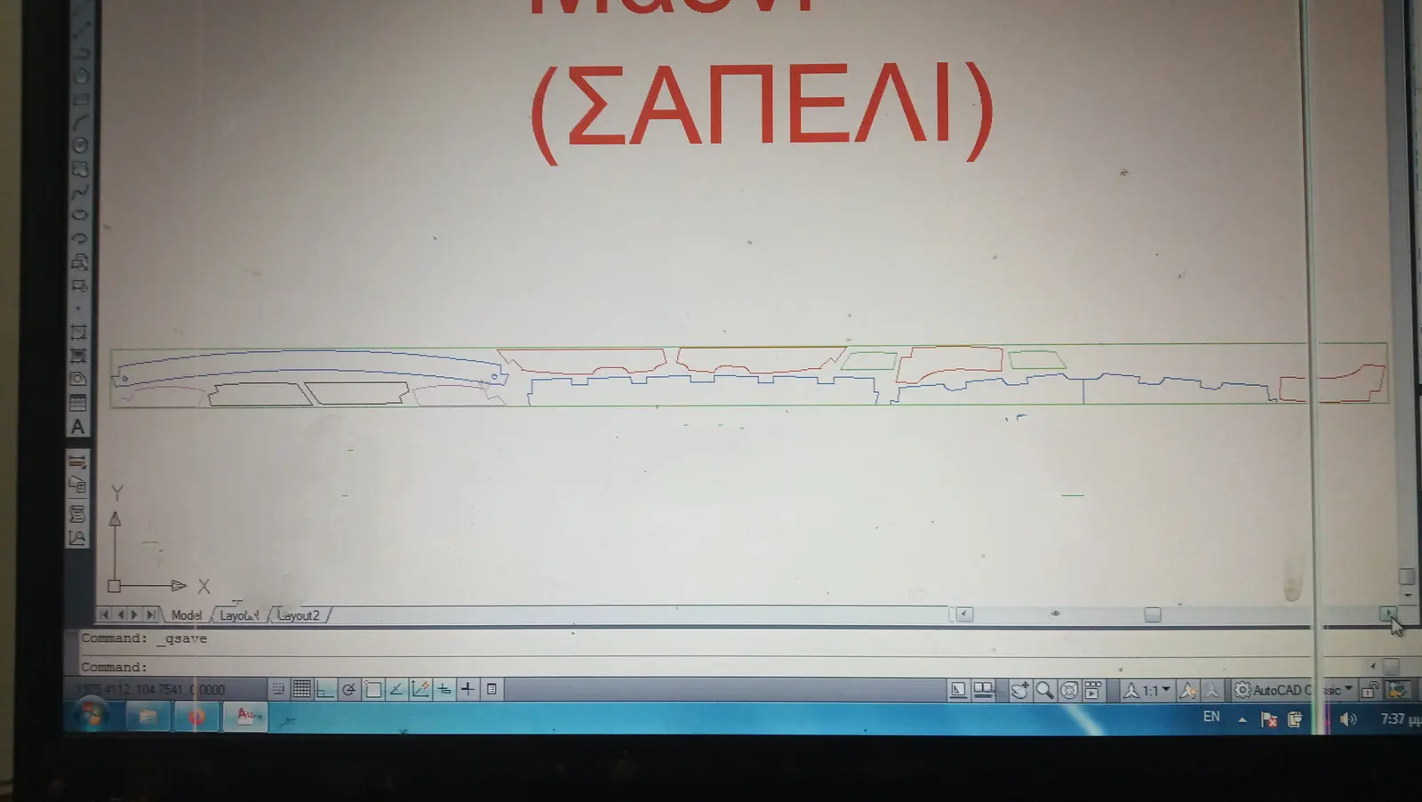
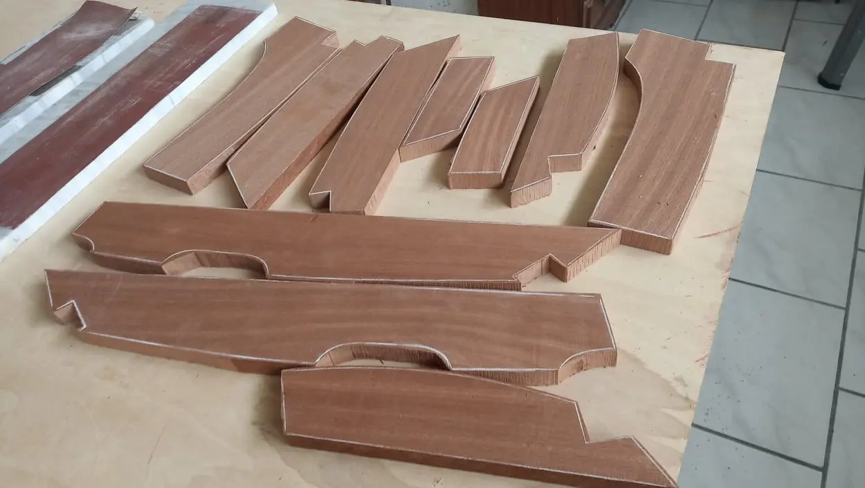
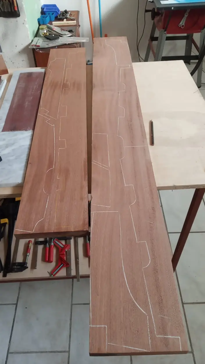
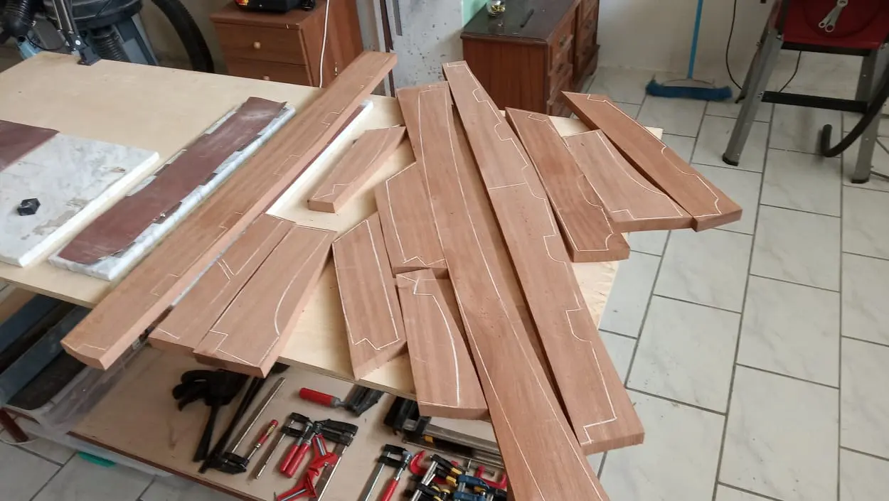
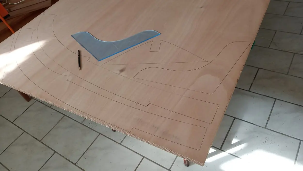
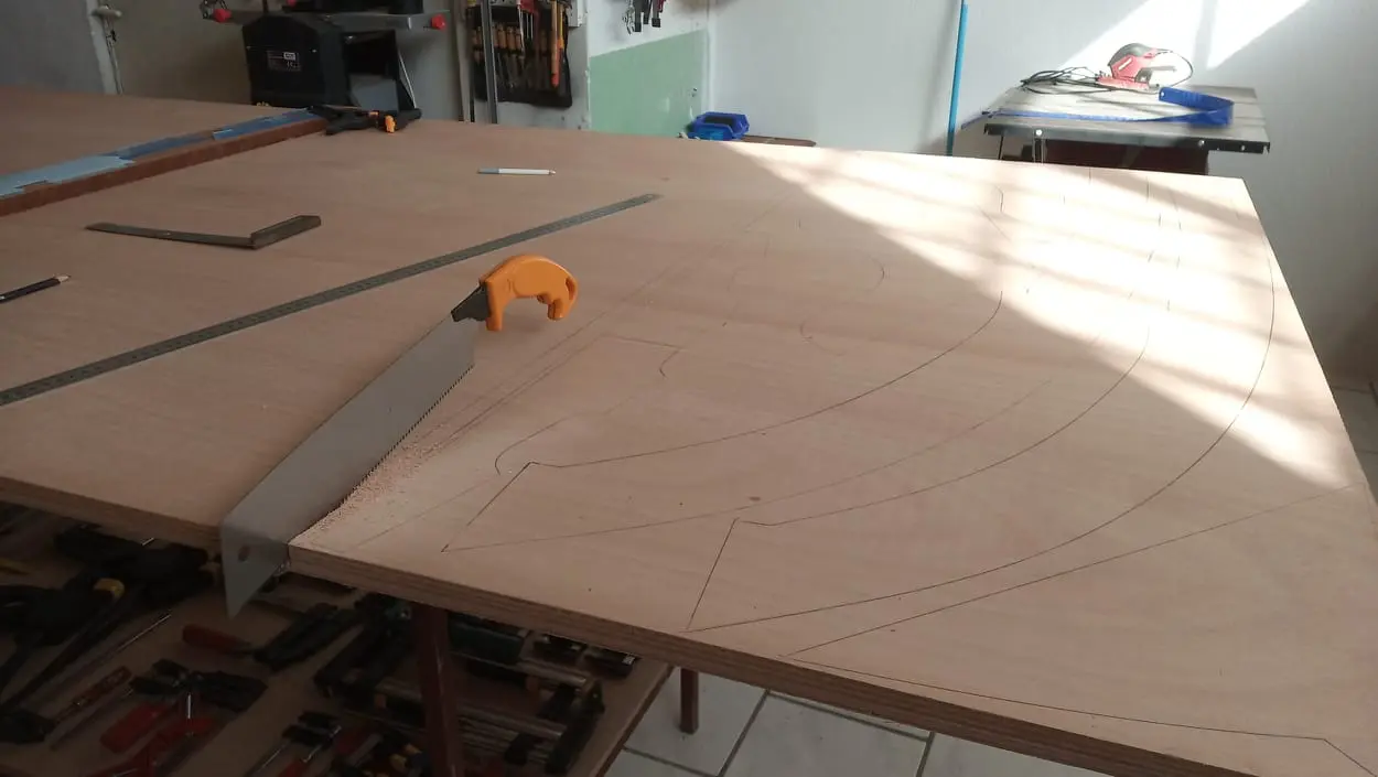
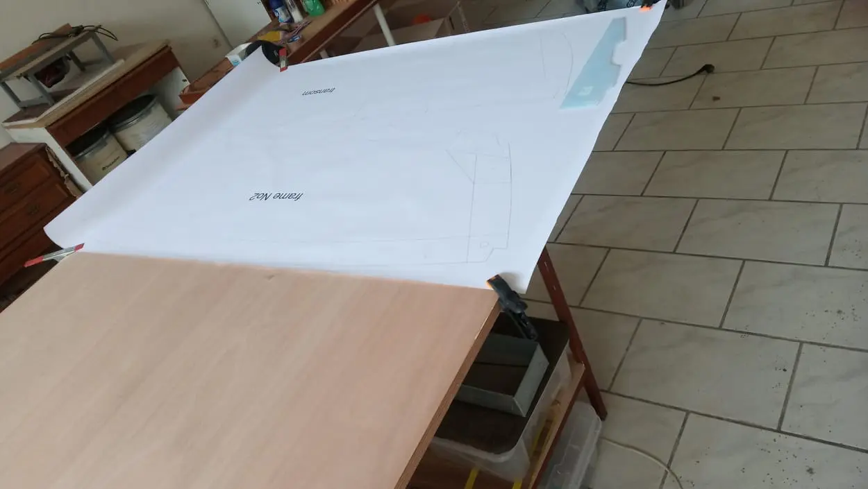
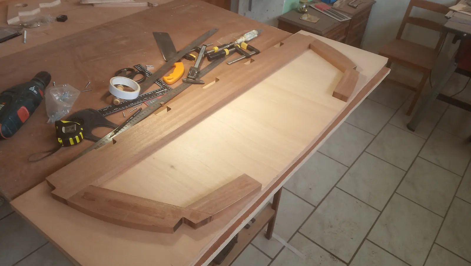
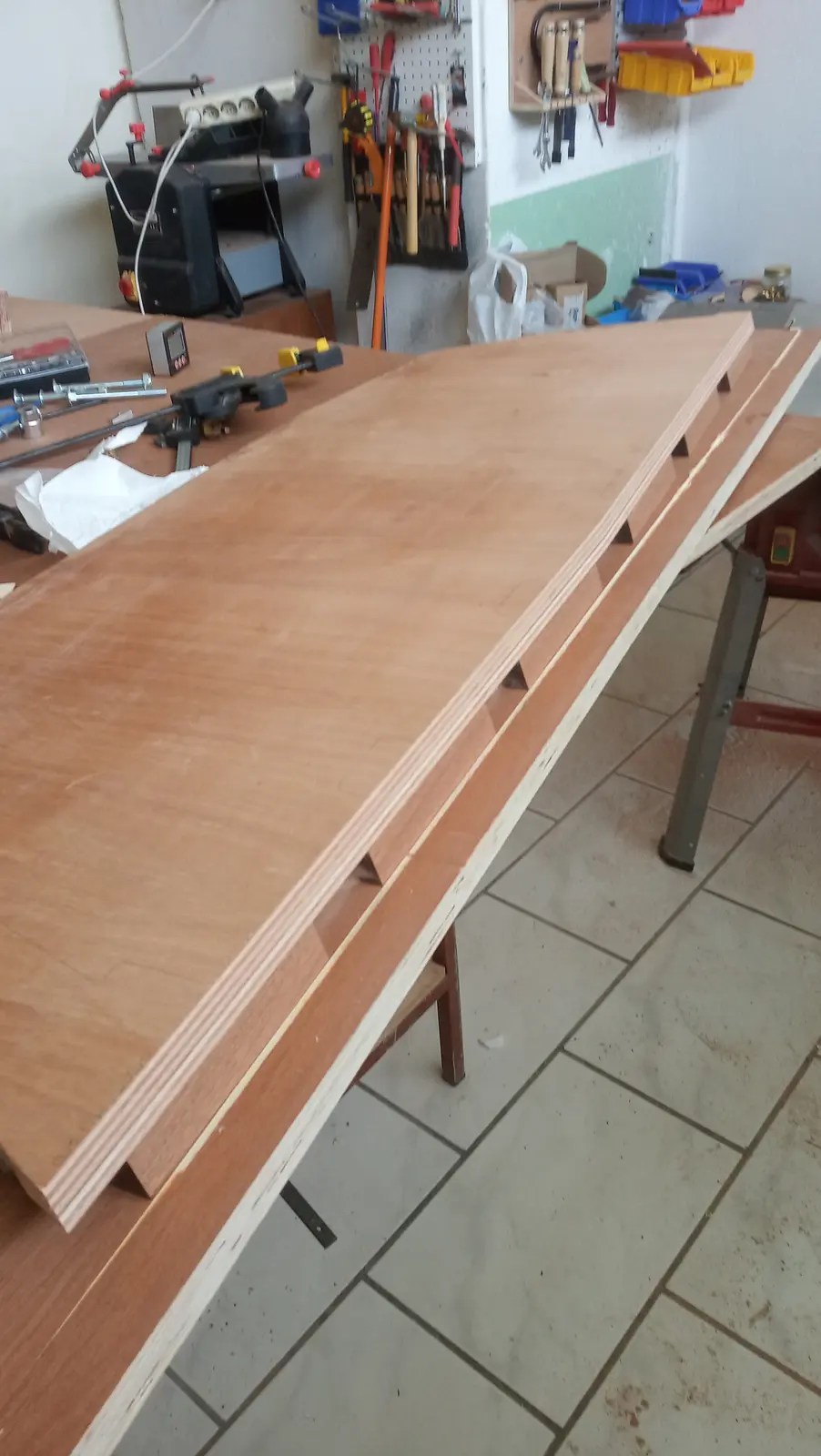
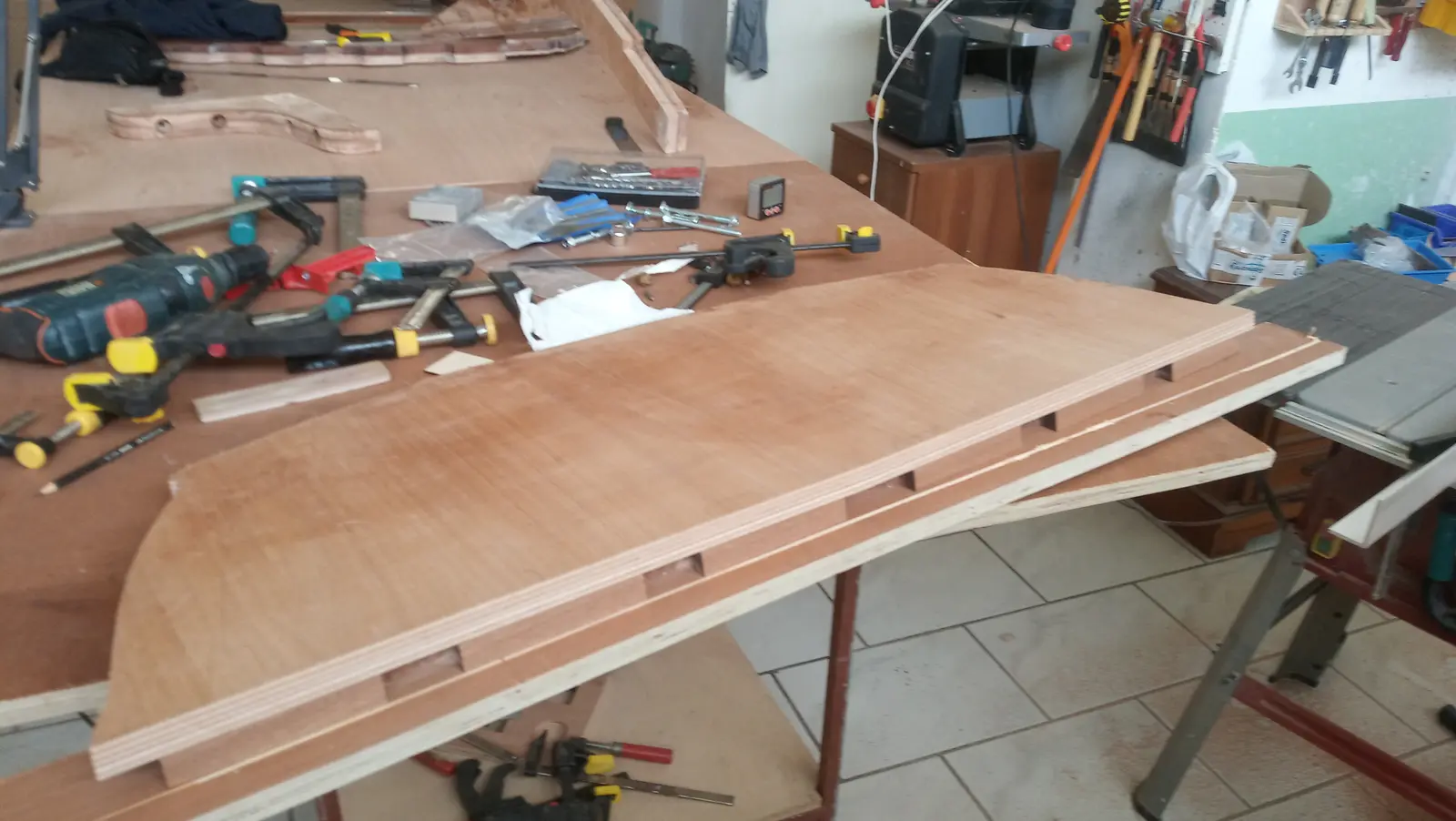
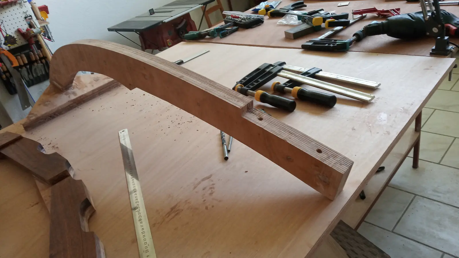
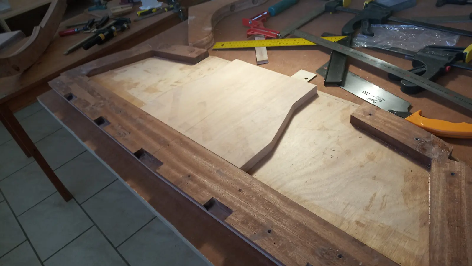
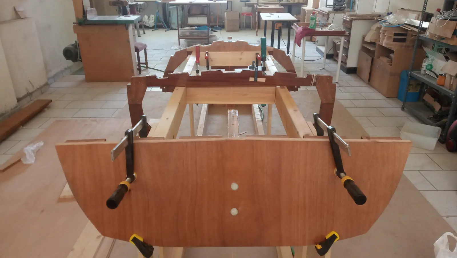
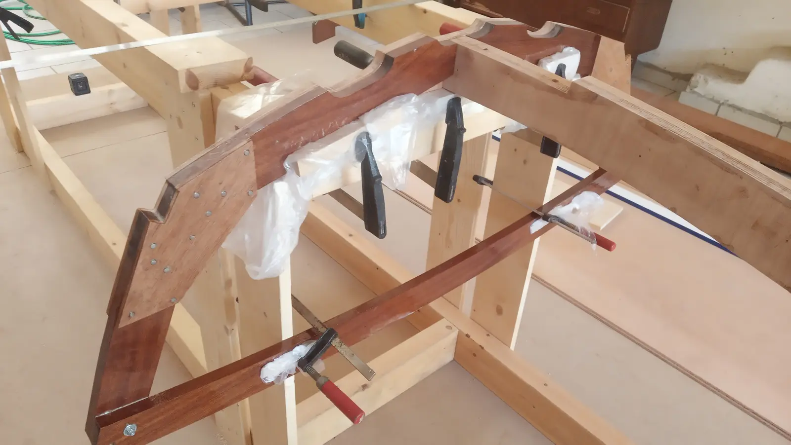
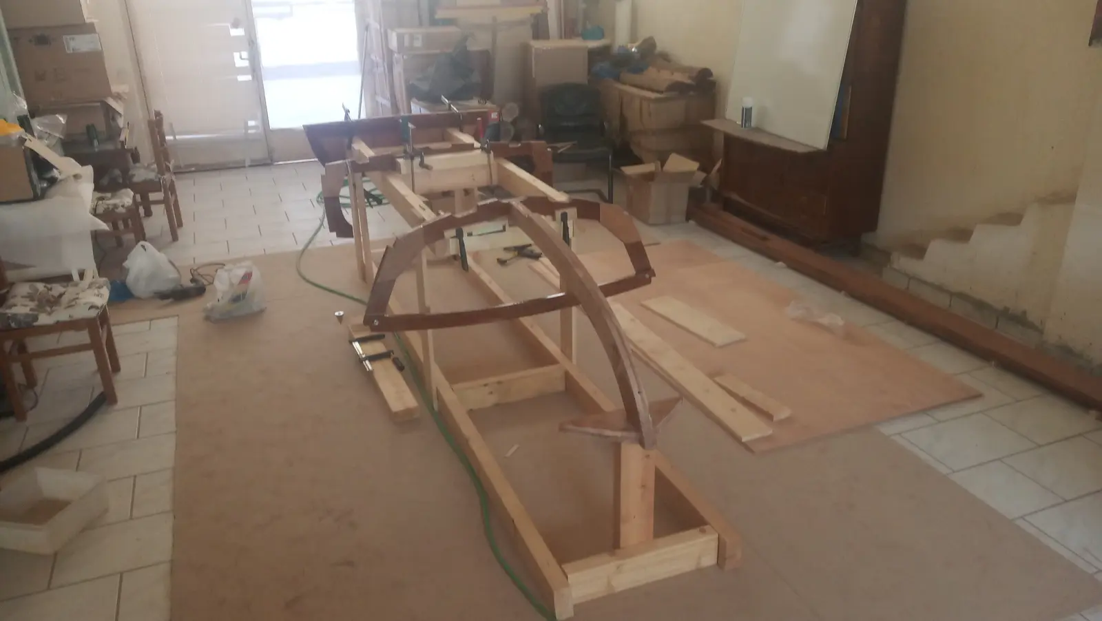
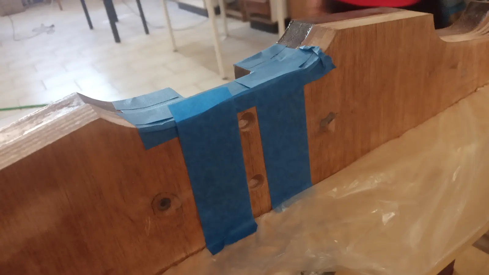
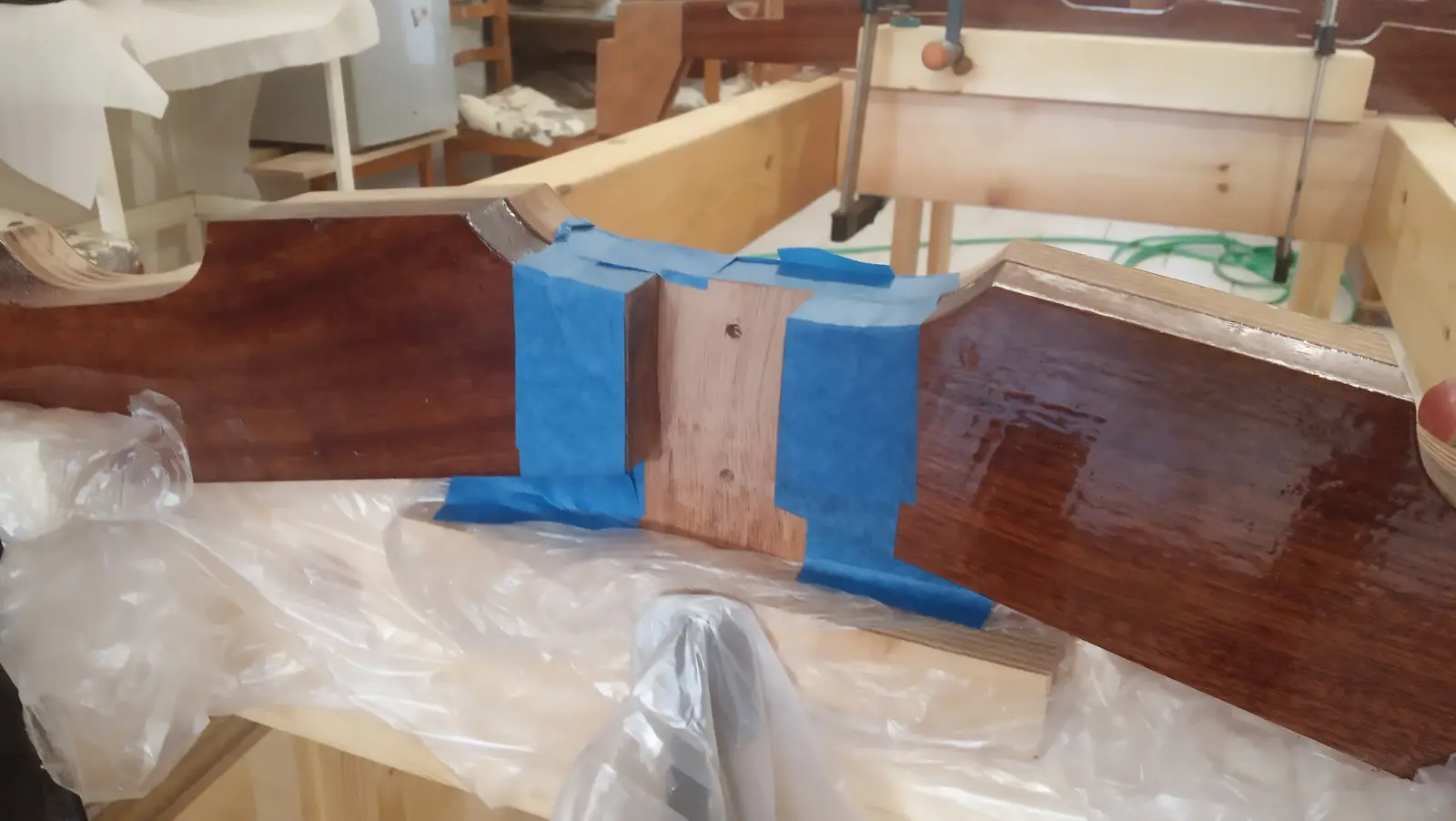
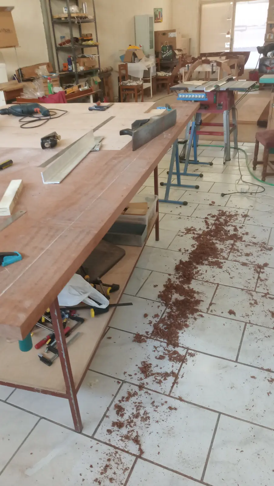
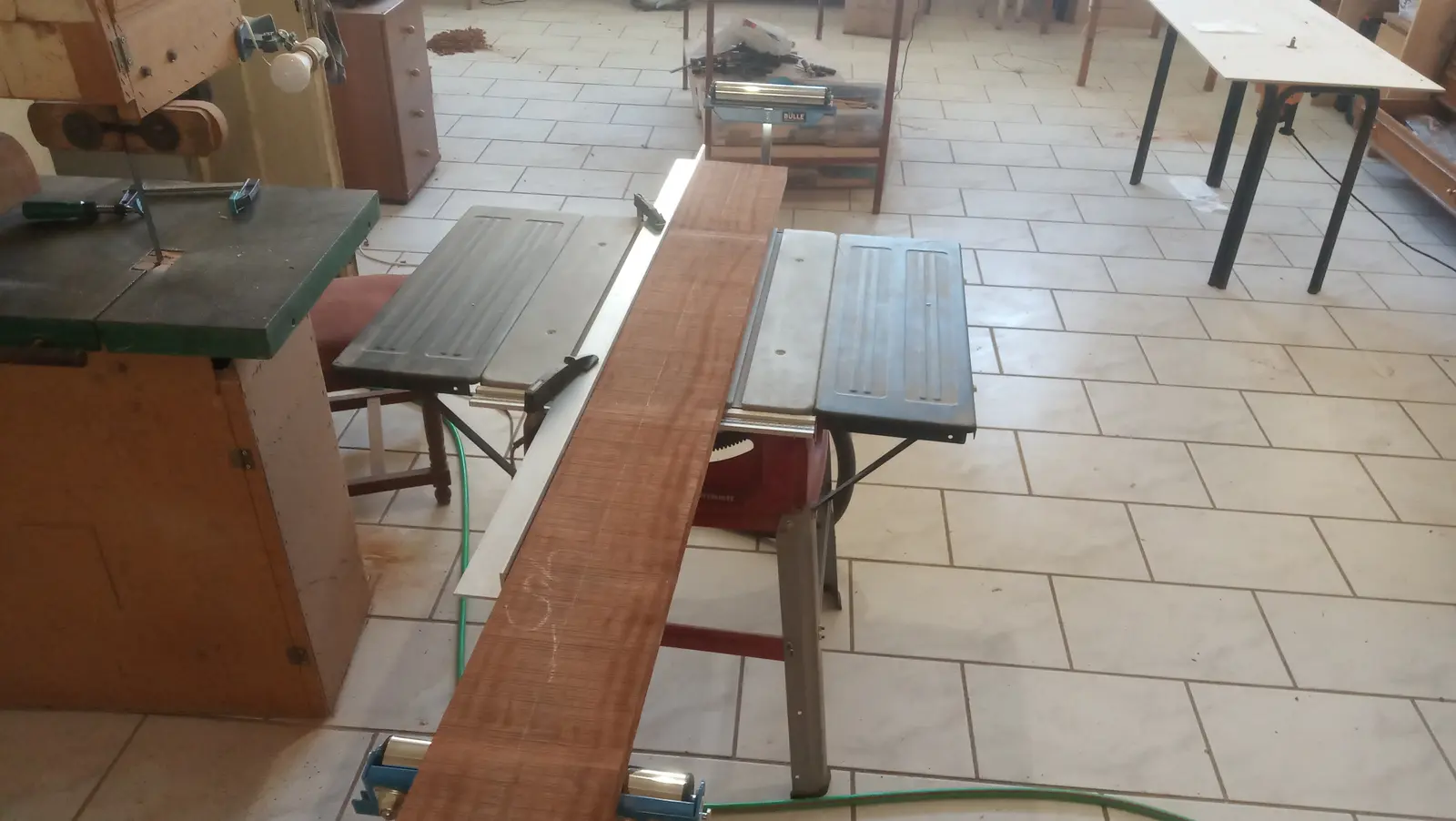
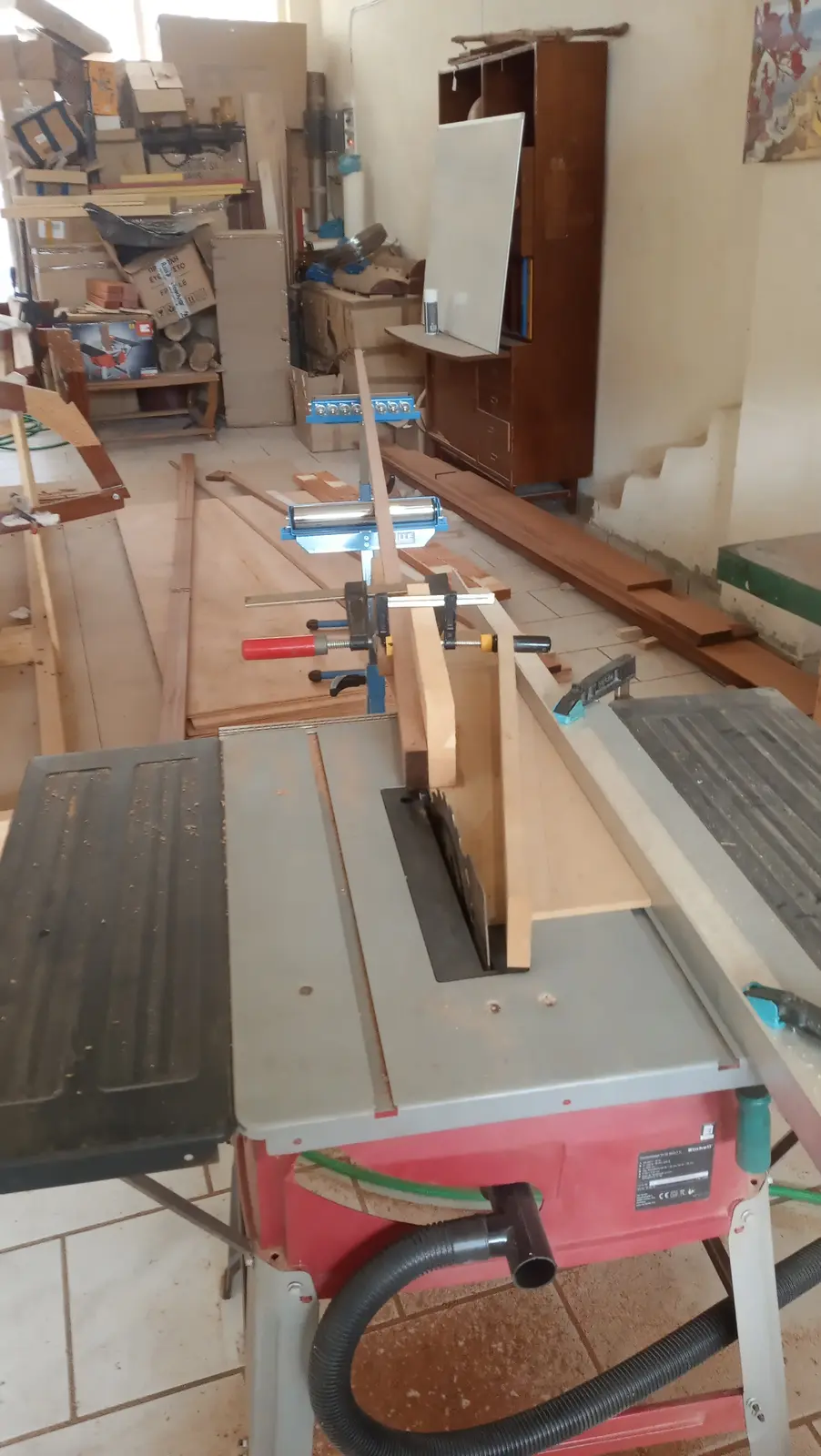
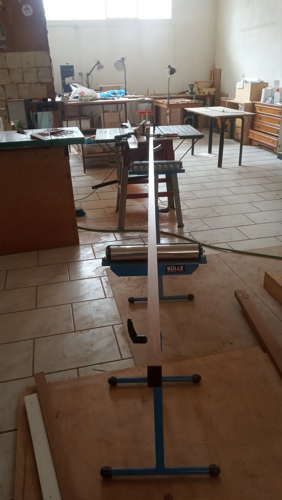
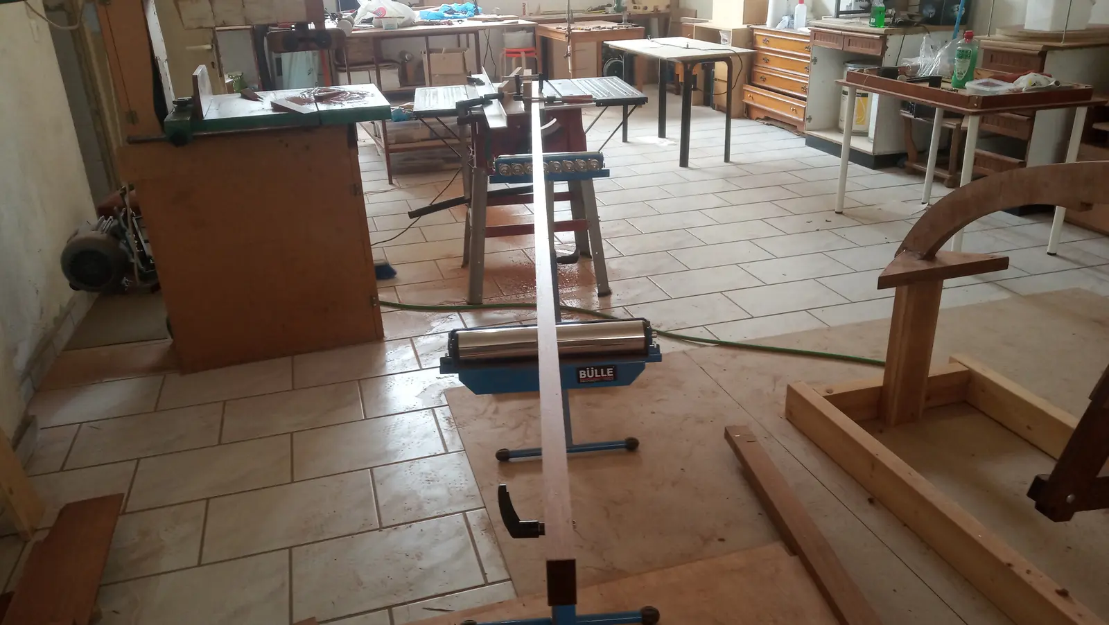
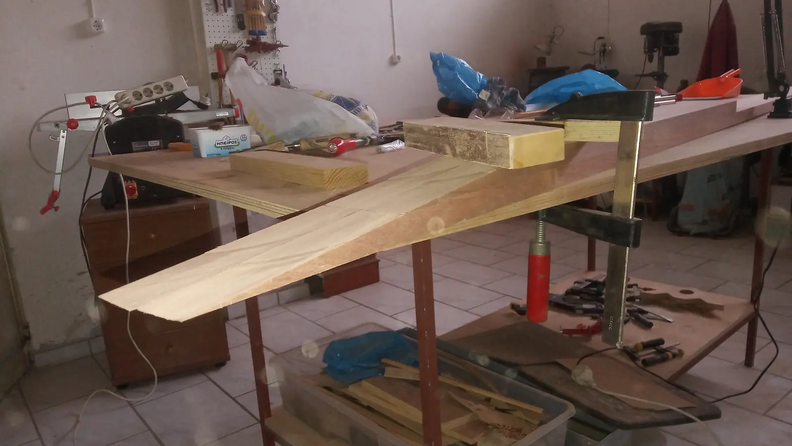
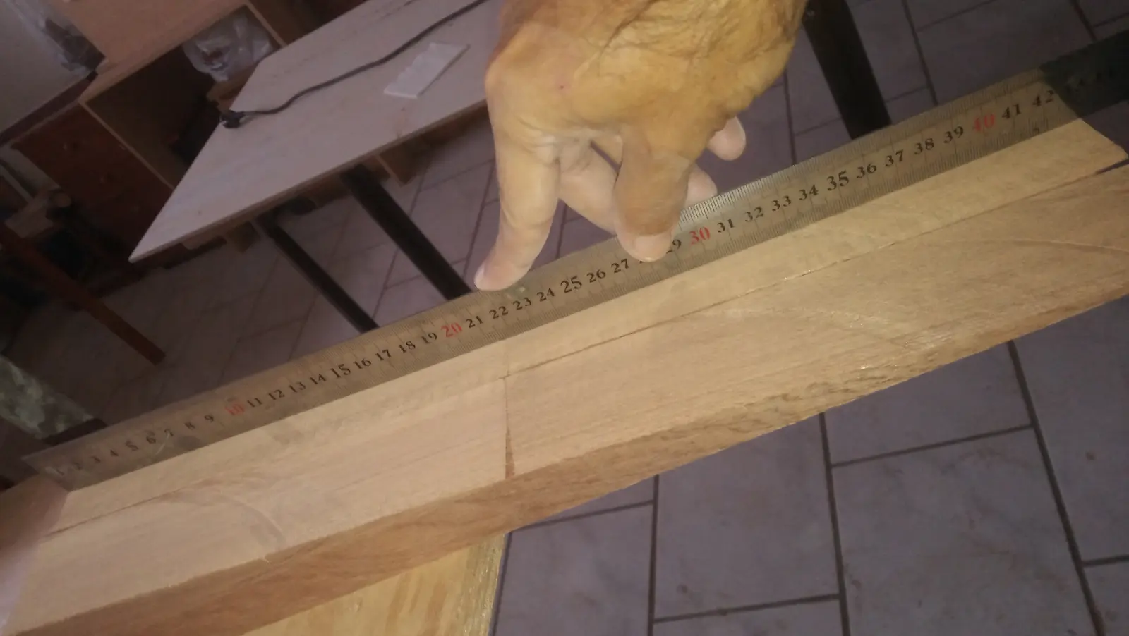
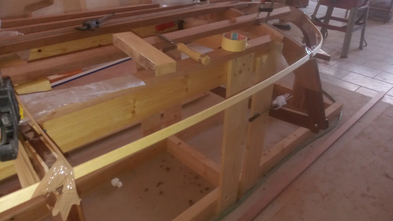
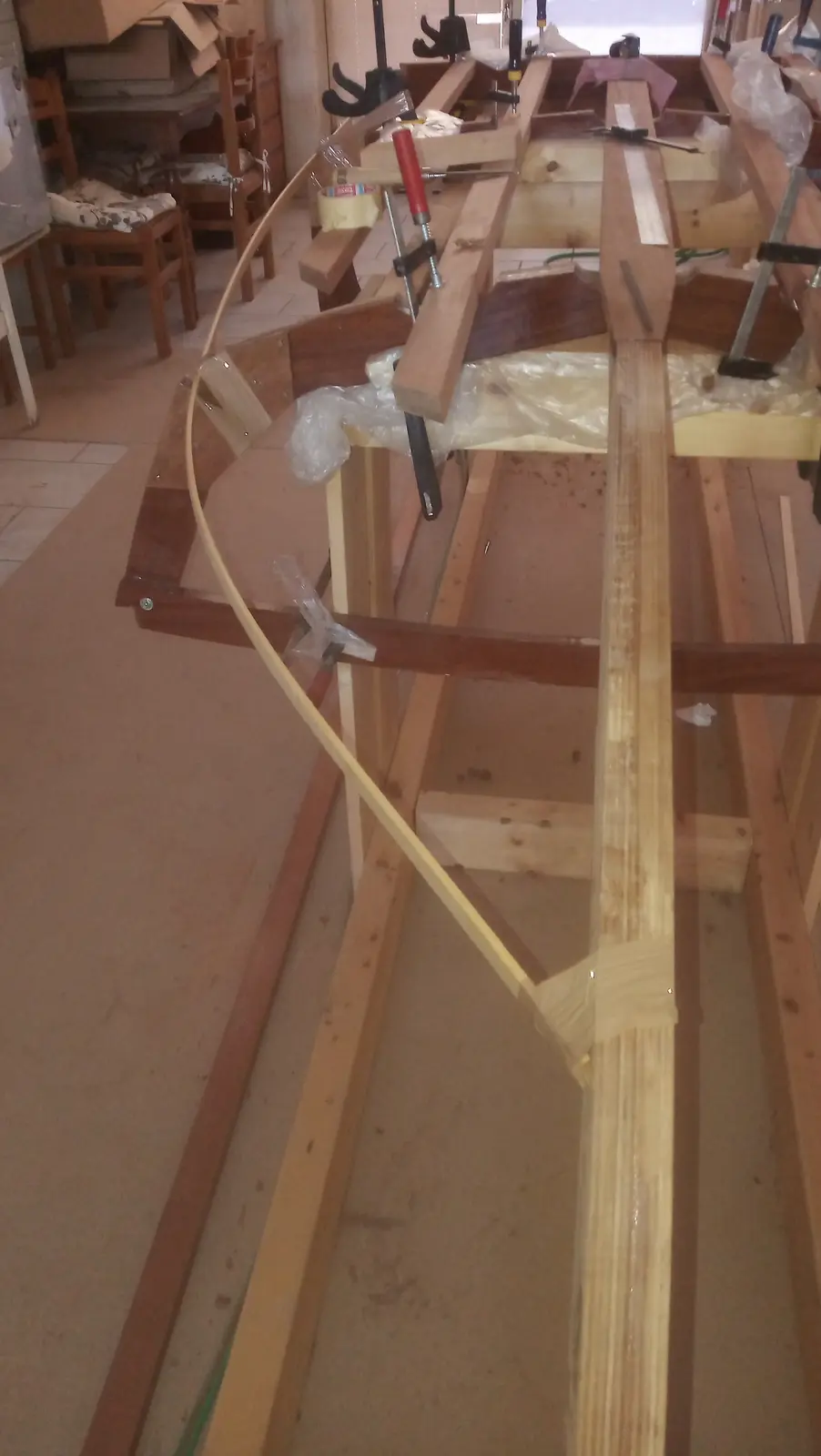
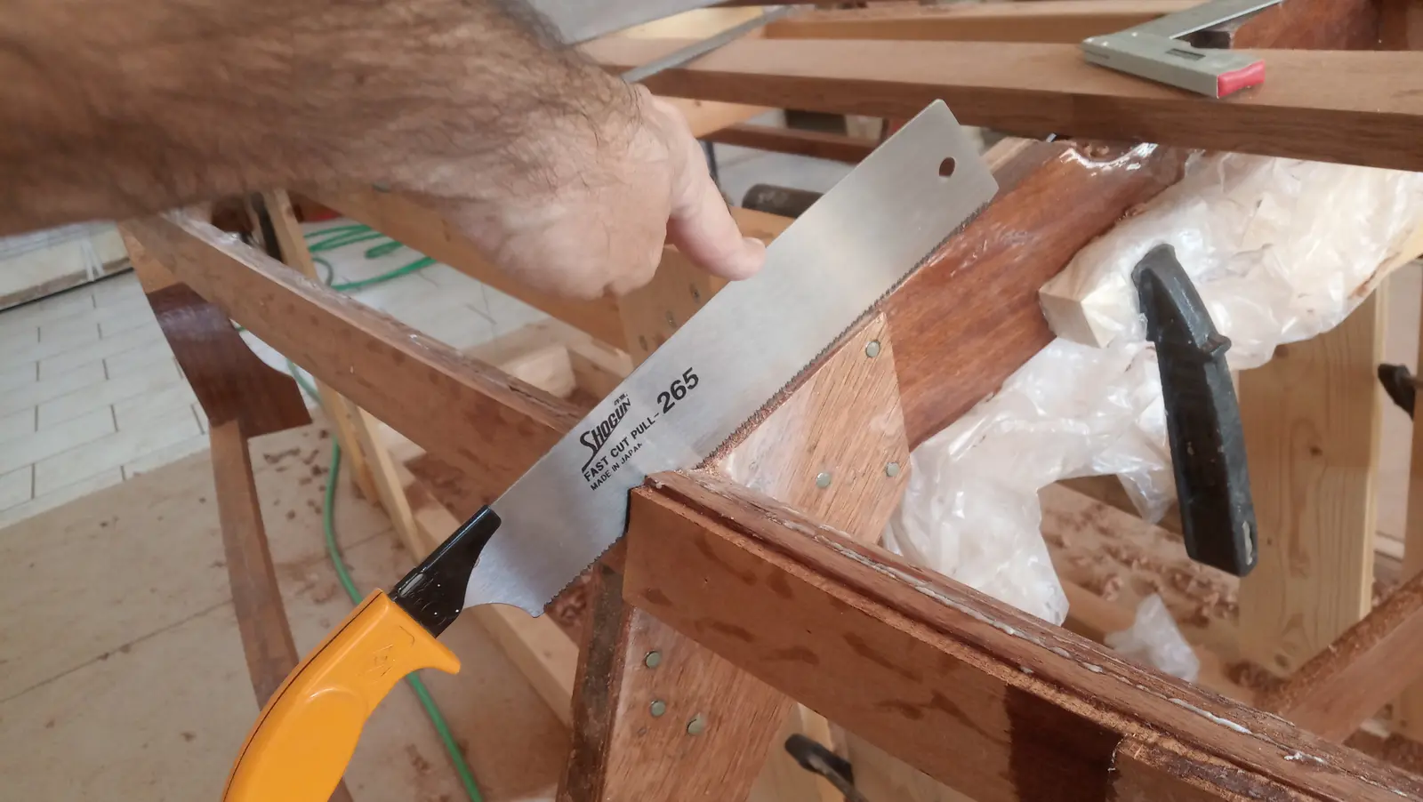
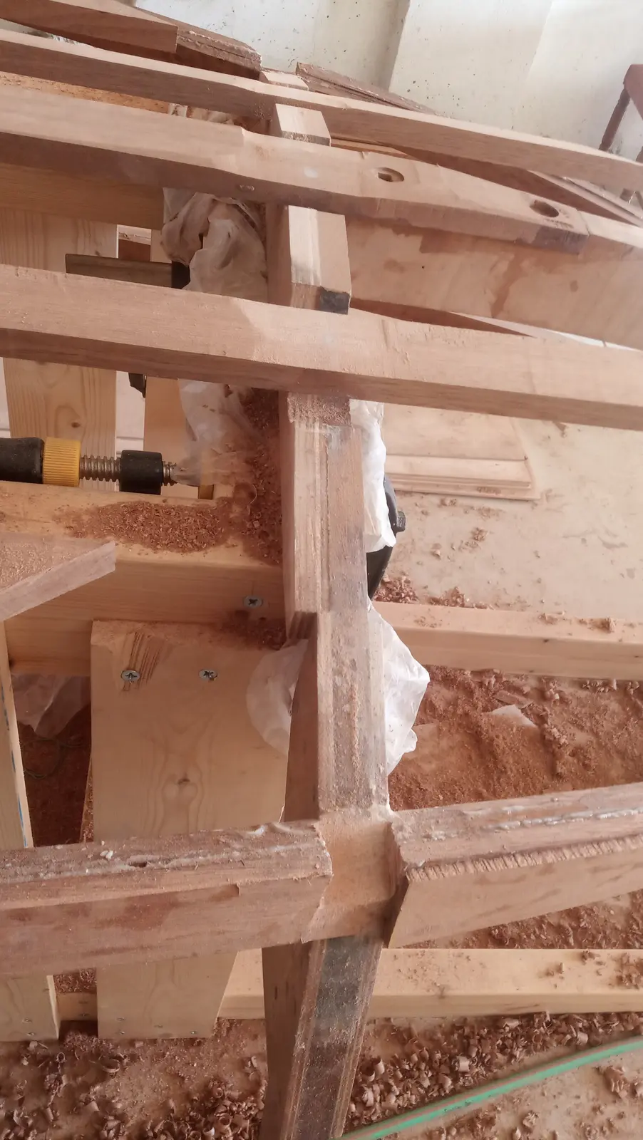
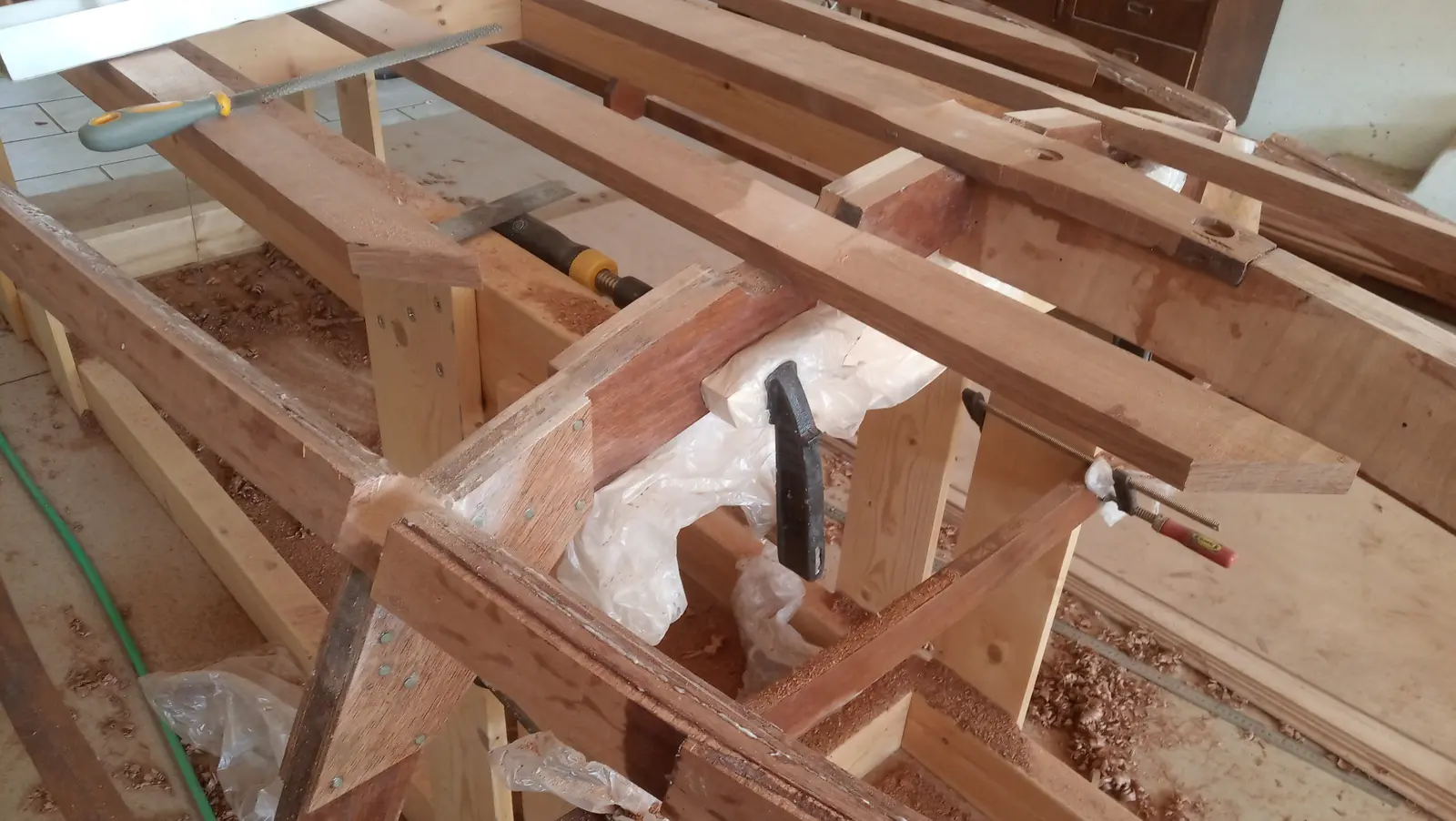
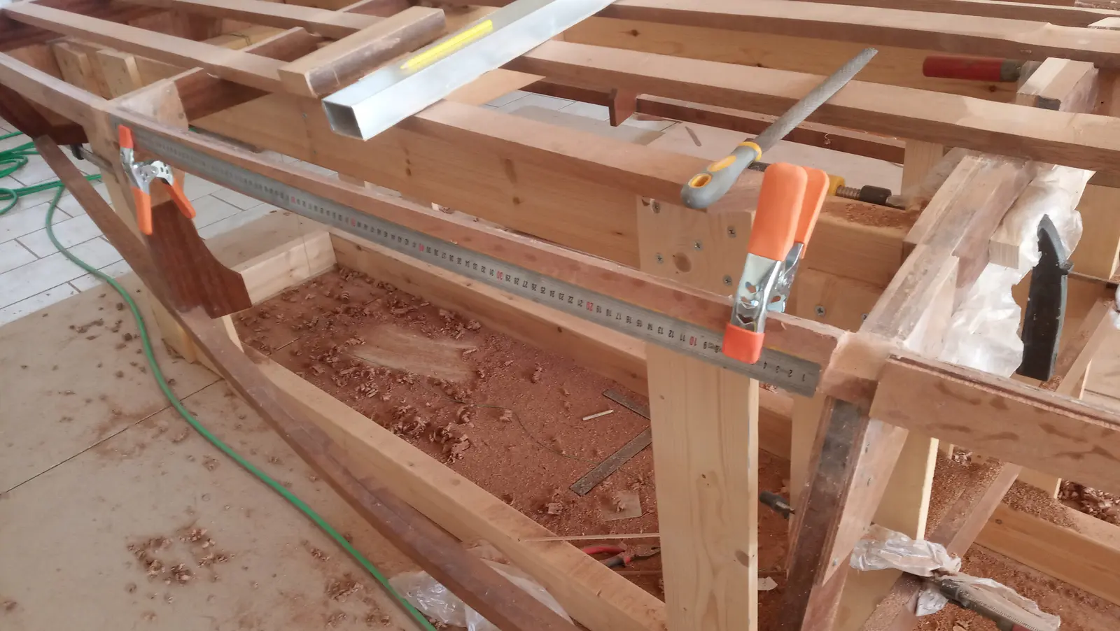
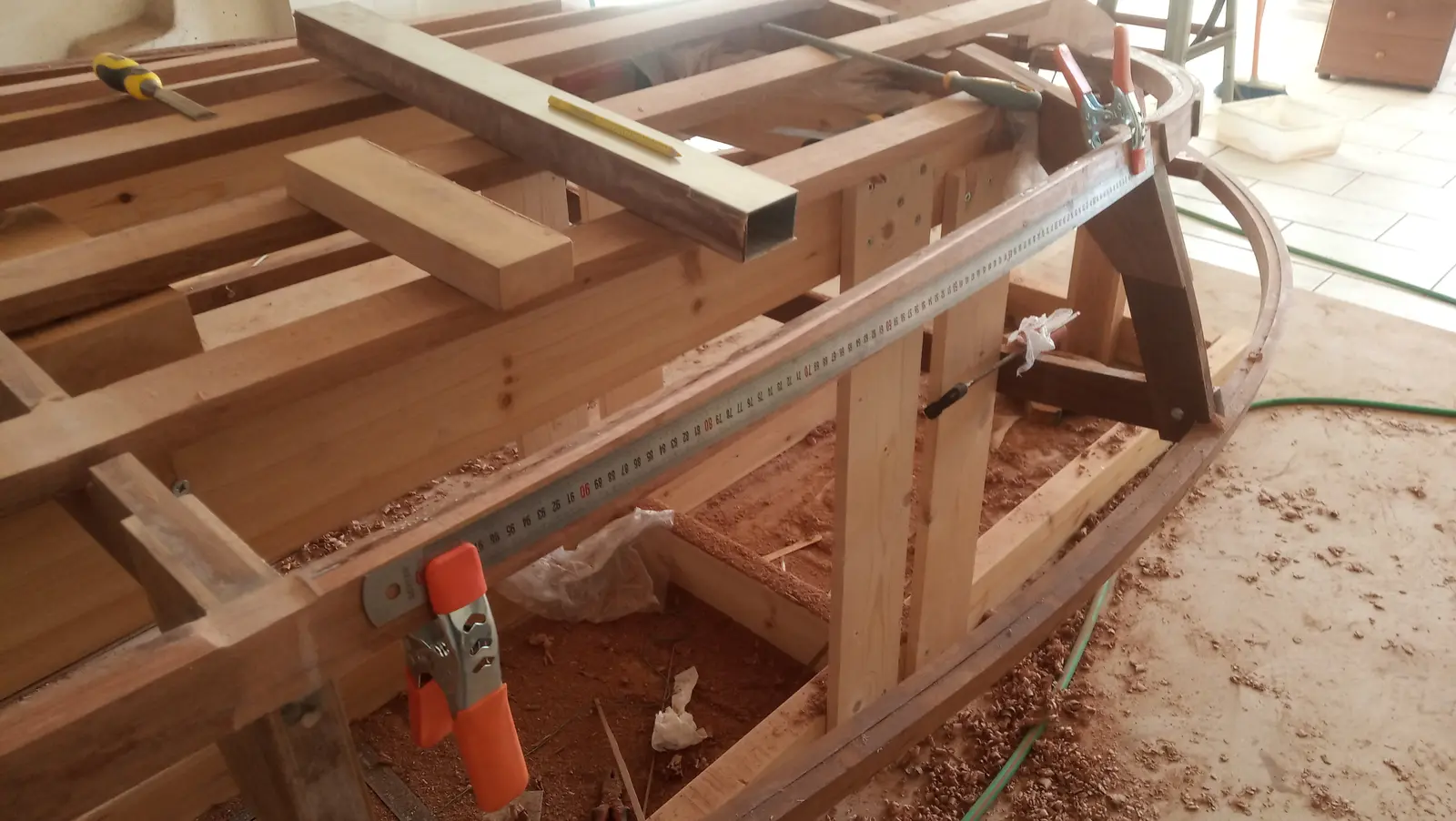
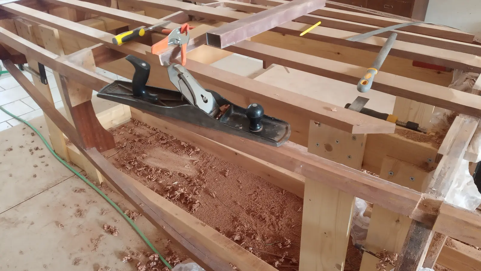
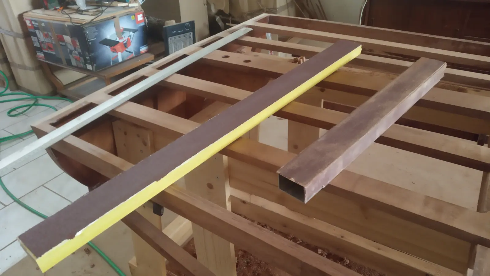
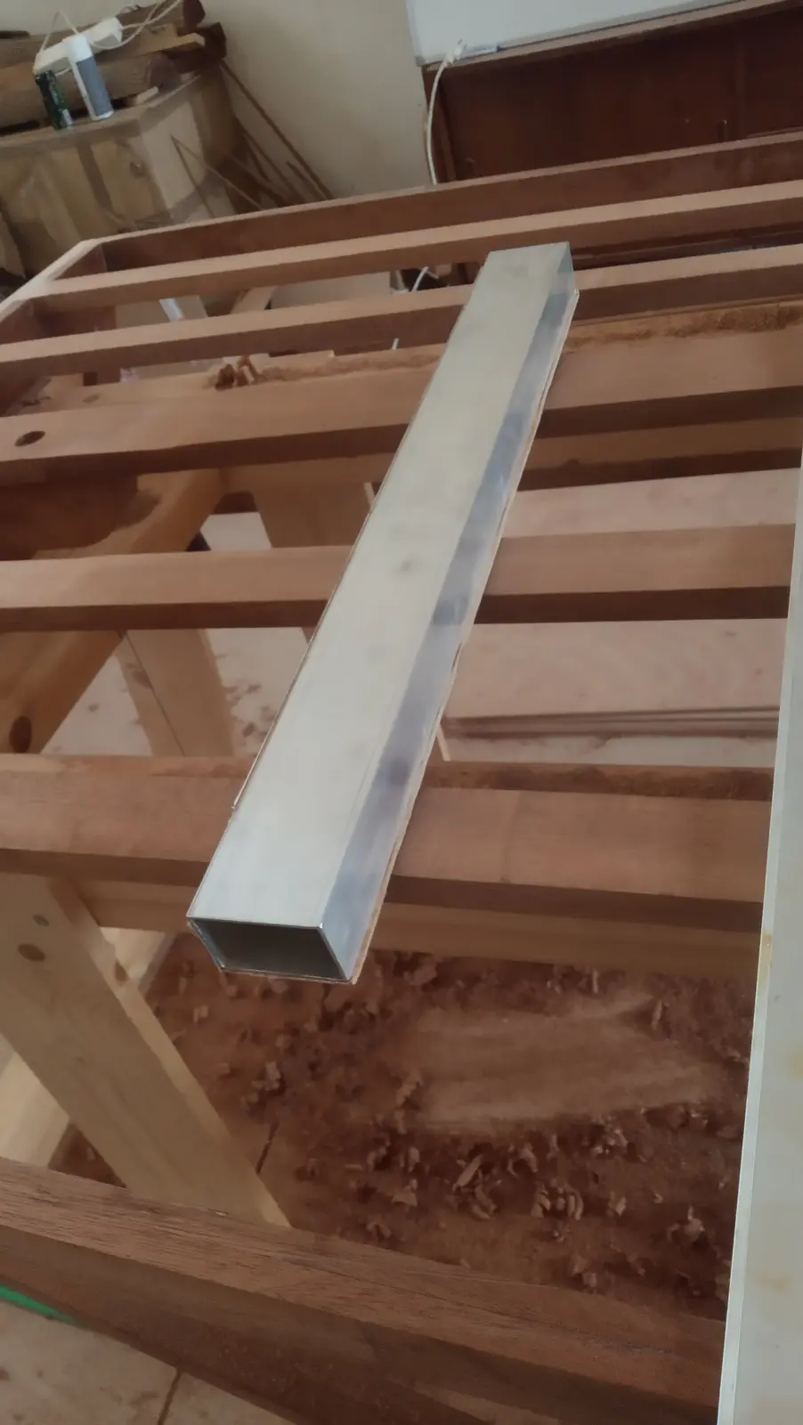
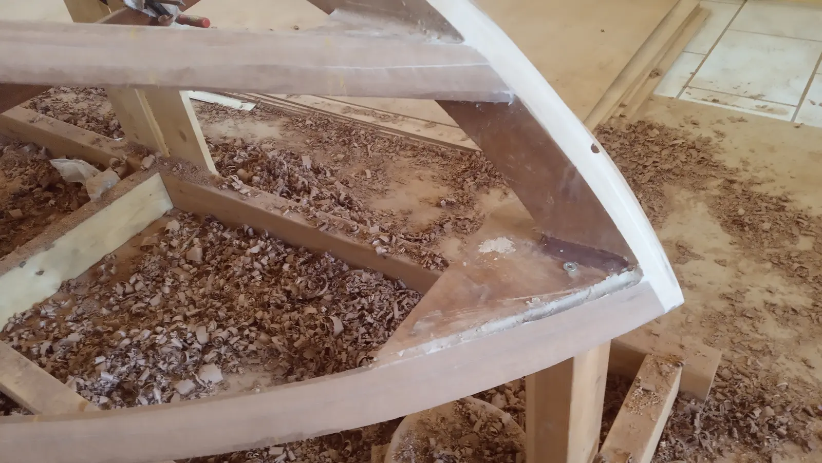
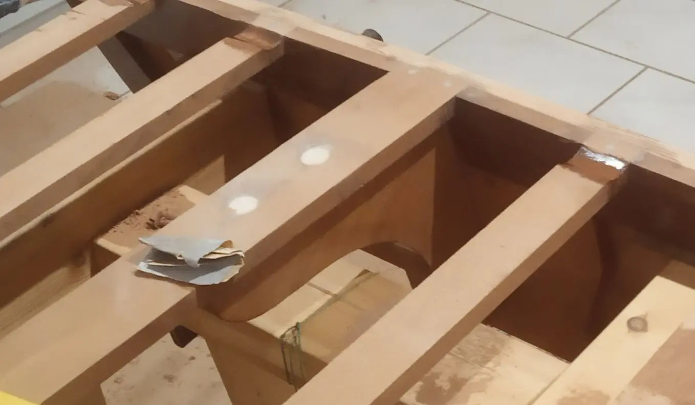
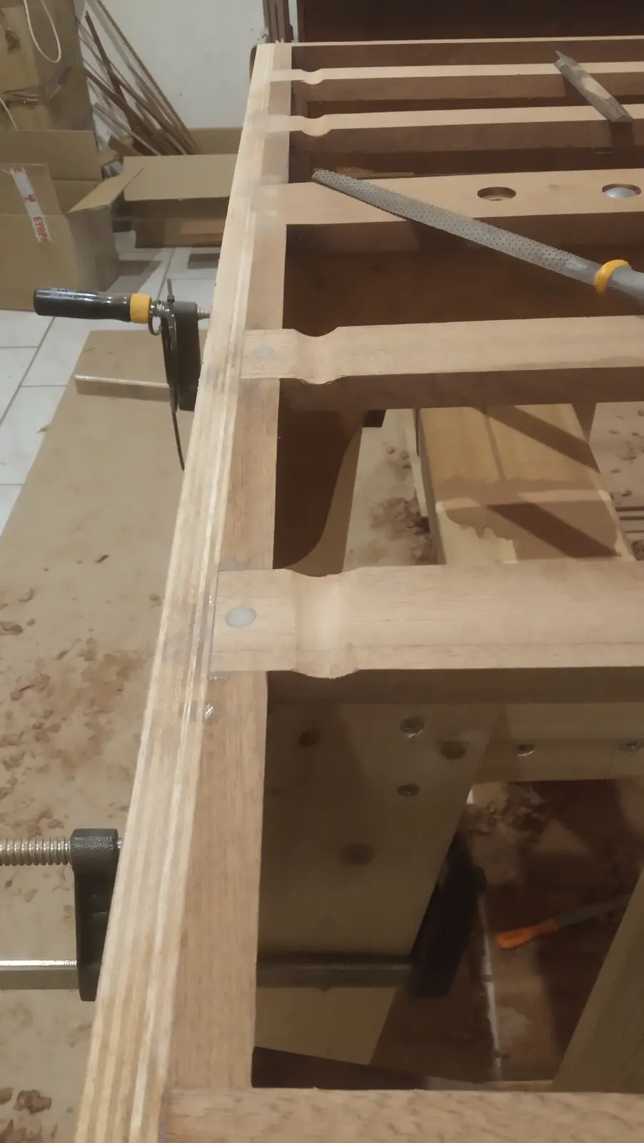
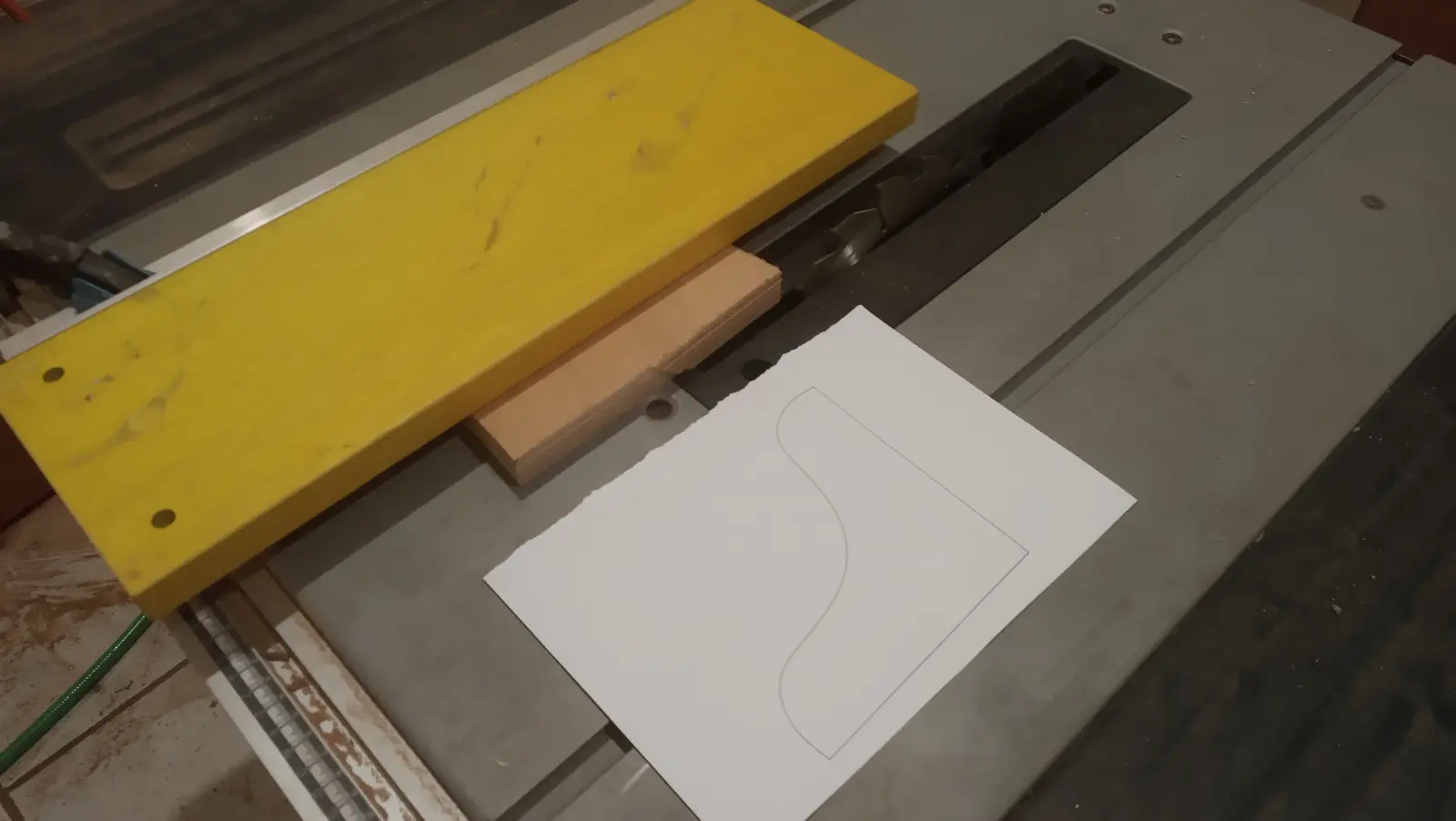
For the side timbers that tie the transom to the frames and the keel (the chines and sheers) I again used sapele and sipo, bought at 8 and 6.5 cm thick. The dimensions are 355 x 32 x 16 (two pieces glued together) for the sheers and 340 x 45 x 25 for the chines (a single piece, which in the end I could not bend. Read on).
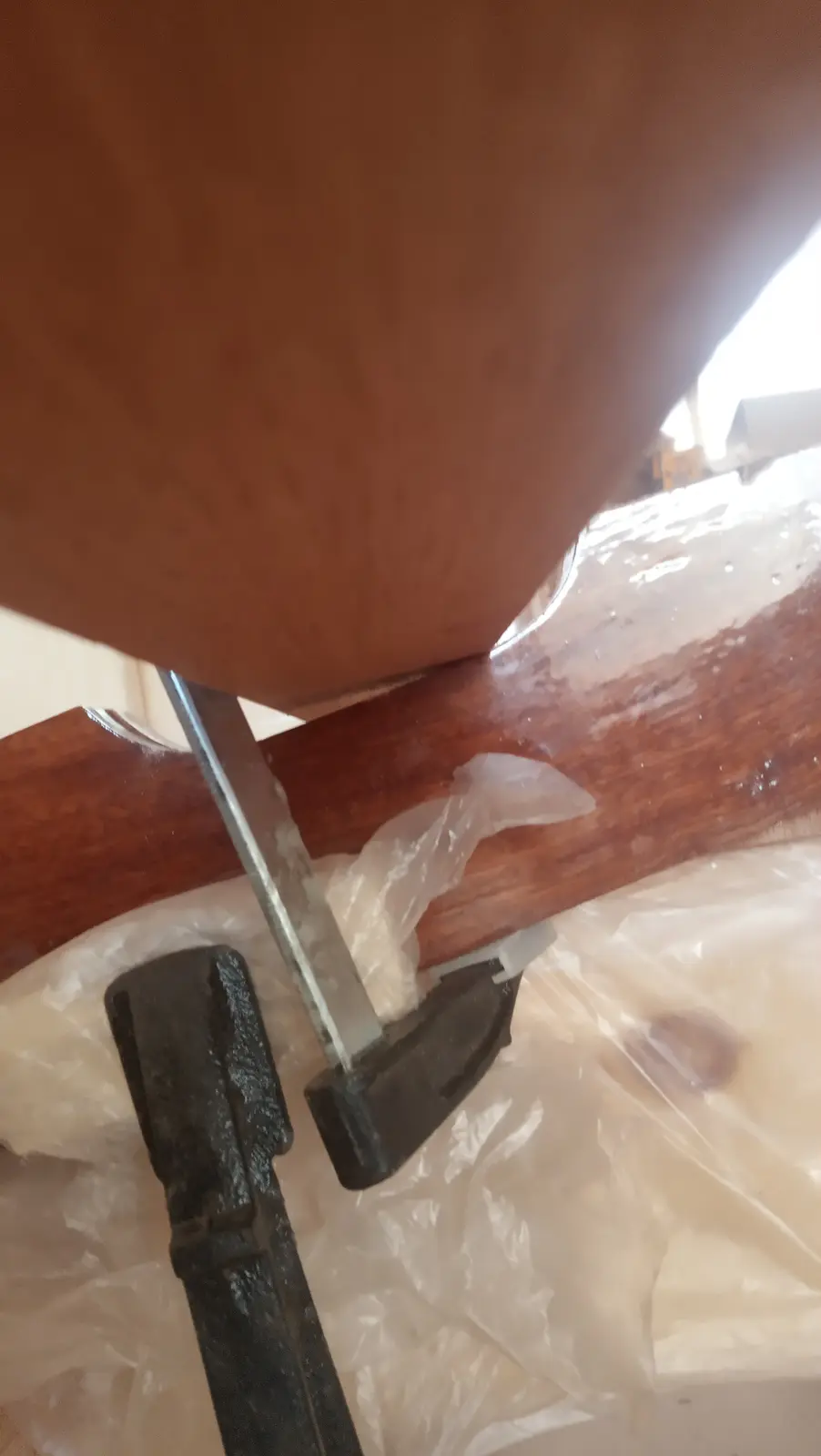
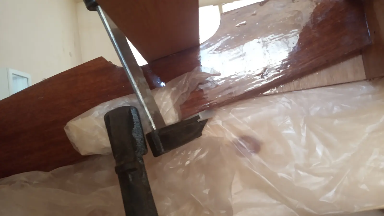
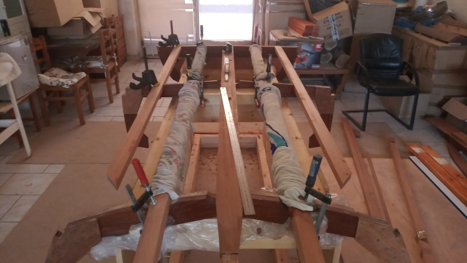
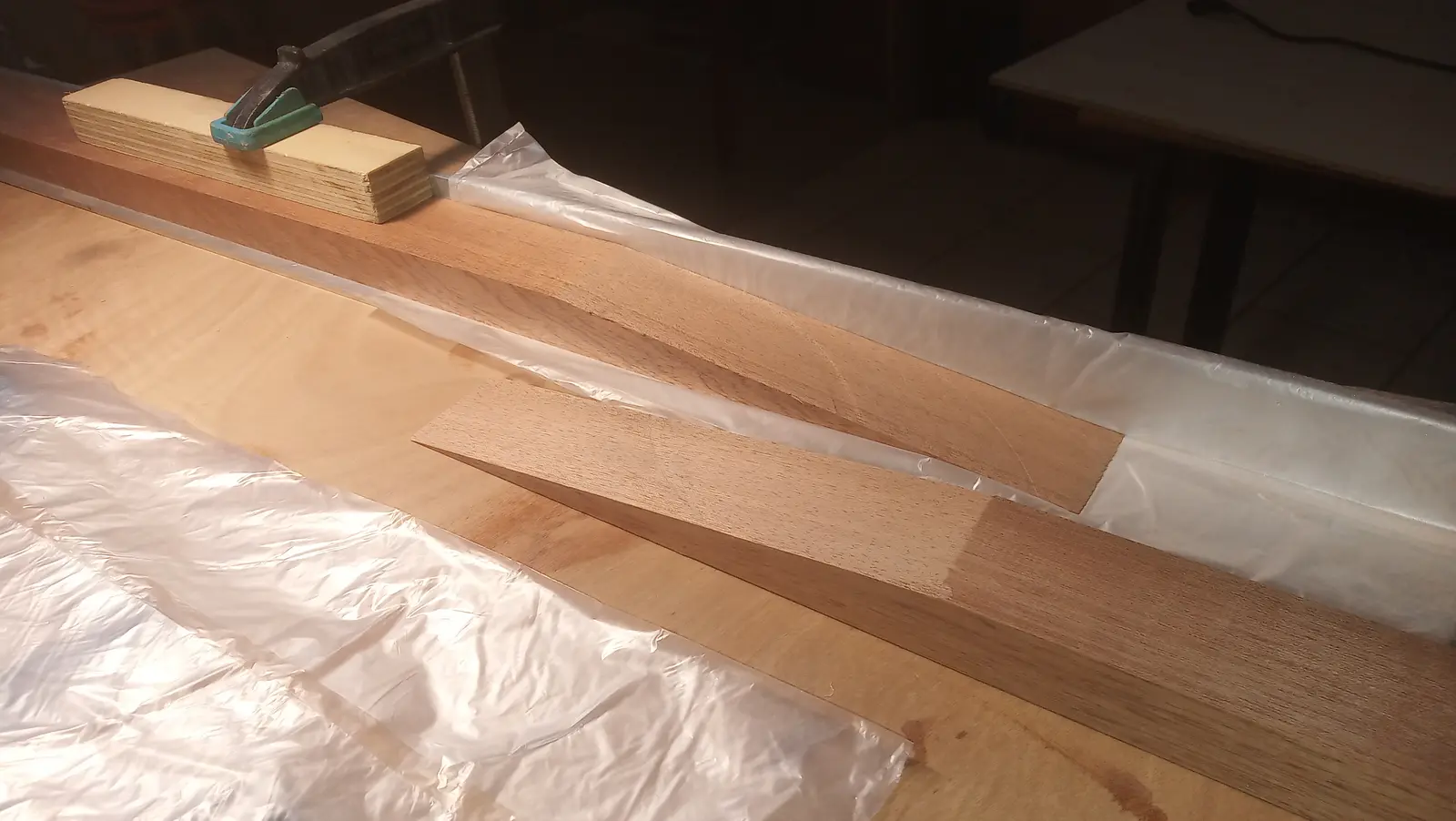
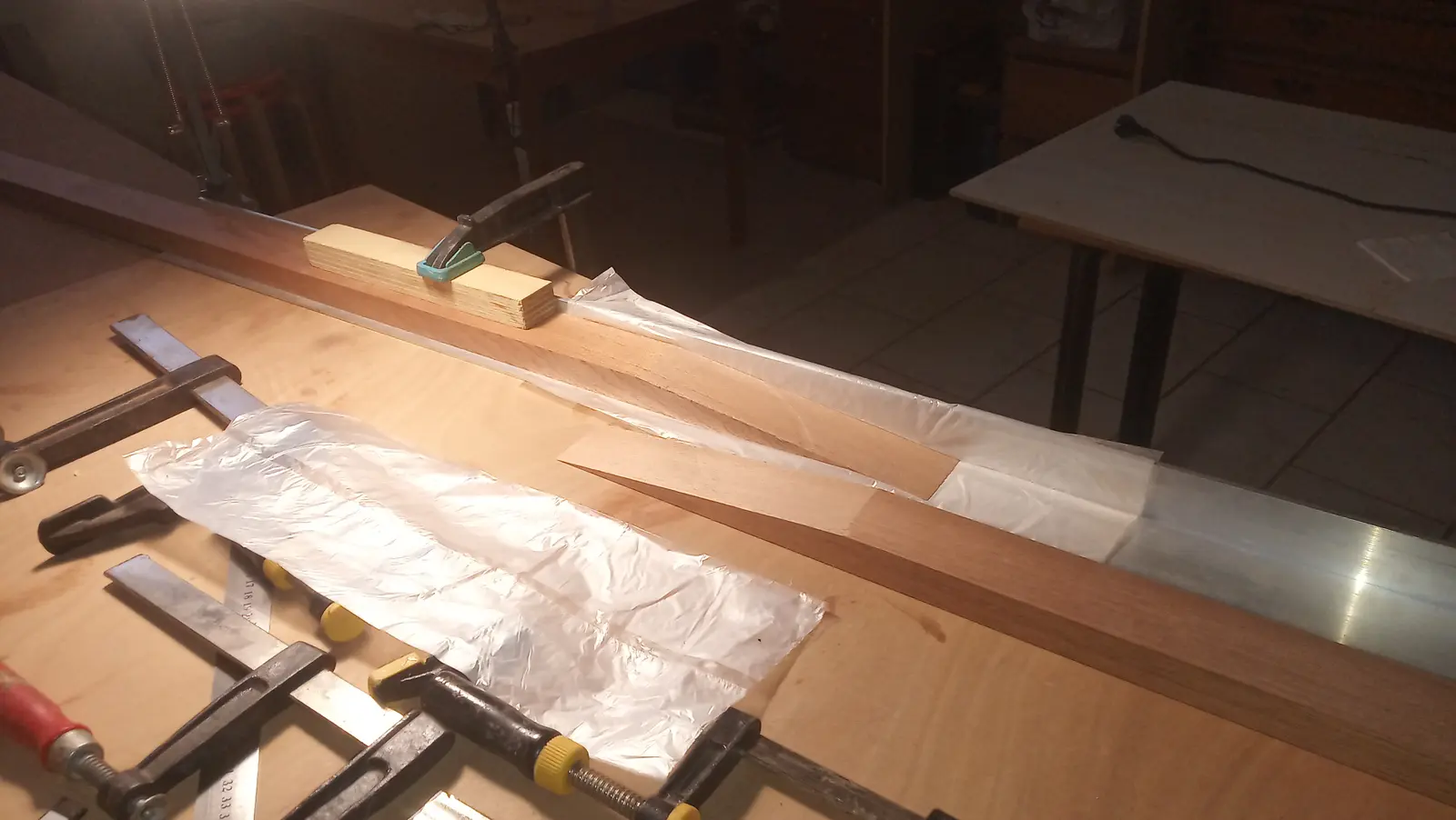
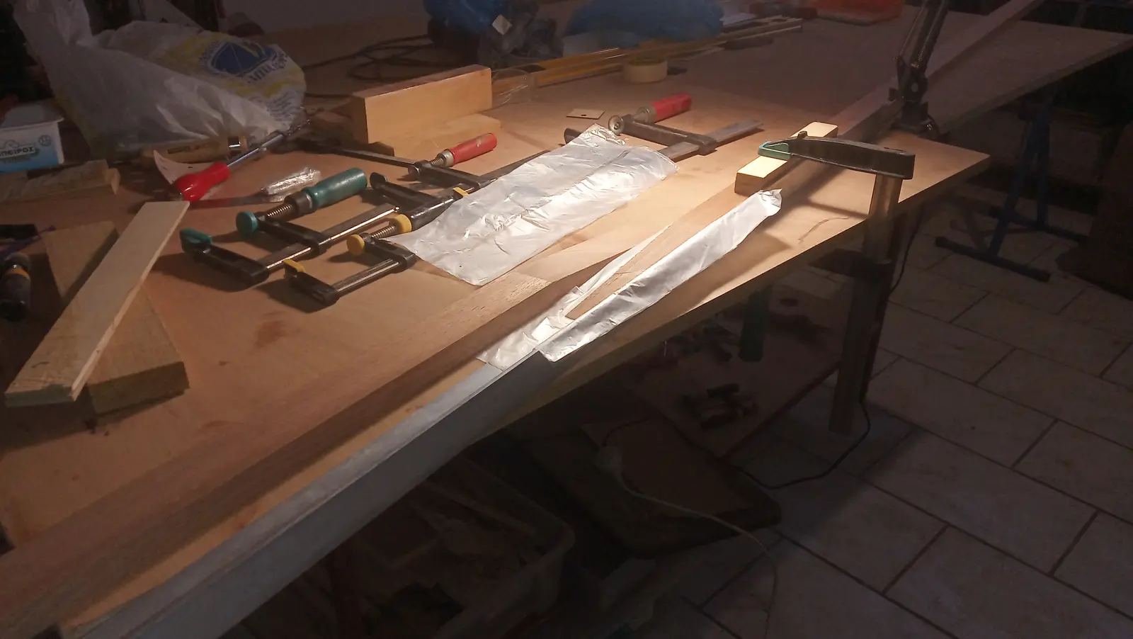
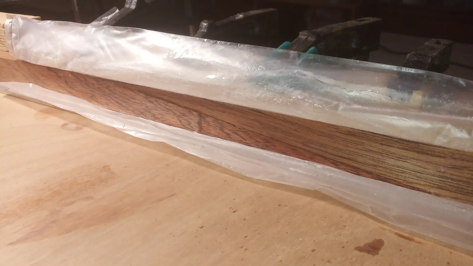
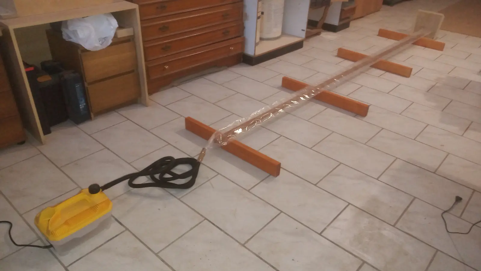
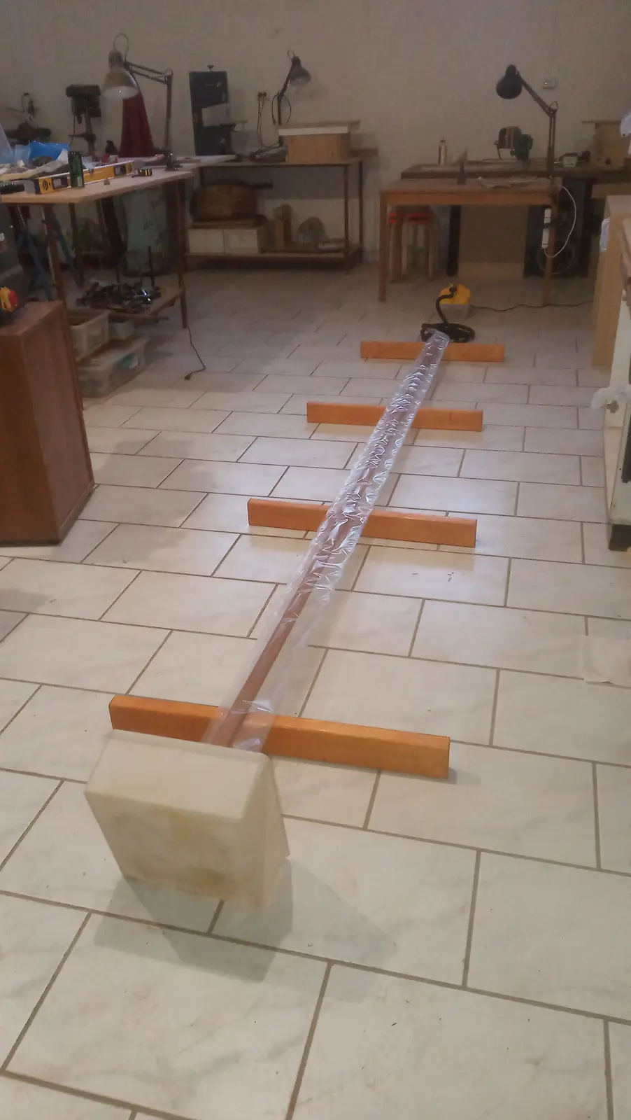
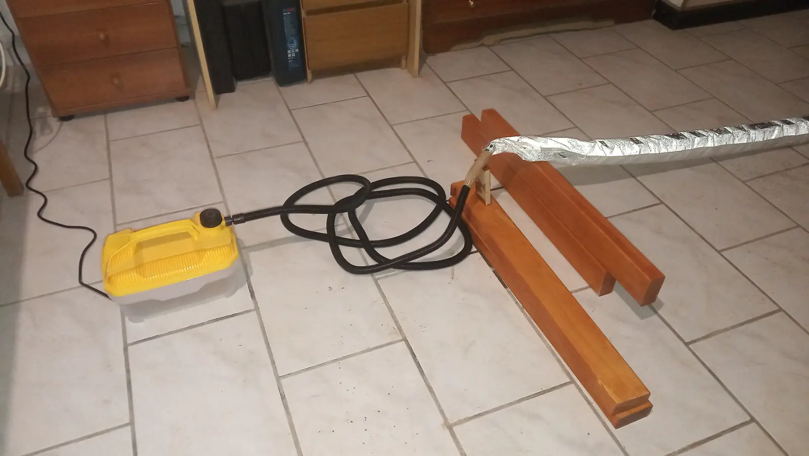
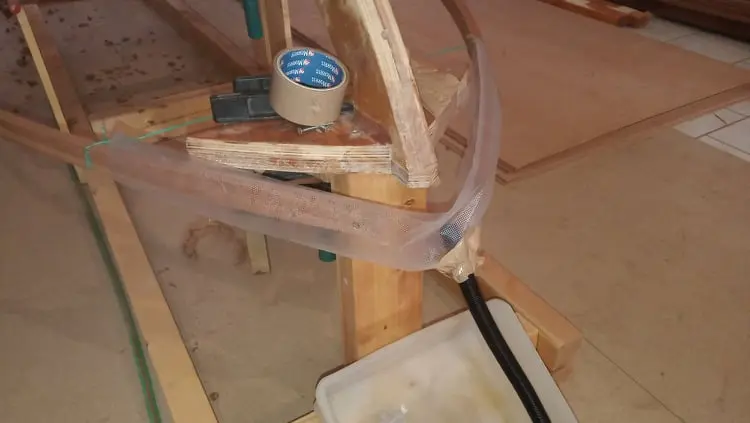
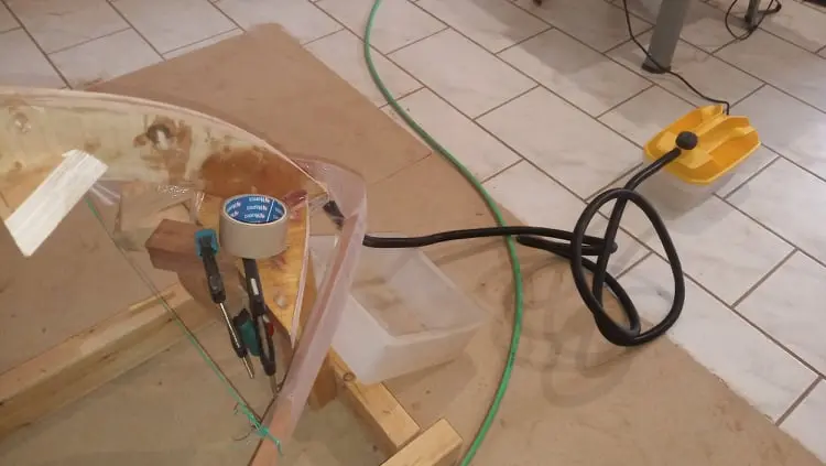
For the bending I used a steamer bought from amazon.com for around 60 euros. I did not make a wooden box or a PVC pipe to hold the steam, I used food packaging bags 5 m long instead. The process I followed is shown below. The bag was closed at one end around the pipe while the other was left open so I could drain off the water as it condensed. Small holes were made in the underside of the bag so water could escape there too, but the damp seems to have stuck the walls together and it did not drain from those. Every so often I lifted the whole arrangement slightly so it would run out of the end.
A few notes on timing. The theory says an hour is enough to bend an inch of timber (about 2.5 cm). Of course a lot of things affect that (the equipment, the species of wood and plenty more, I imagine).
I filled the steamer almost to the top with water (half a finger below the max) and plugged it in. Fifteen minutes later steam started coming into the bag. Four minutes after that it had filled to the far end and steam started escaping. After about 20 minutes I decided to take some water out, I reckon a finger and a half to two fingers, because I thought it would boil more easily. The steamer switched itself off exactly when I was going to switch it off anyway (the water inside reached the limit) after 50 minutes. Even though the timber was 1.6 cm thick and the theory says 35 to 40 minutes would have been enough, I left it a little longer to be safe.
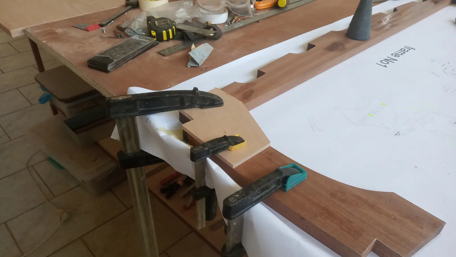
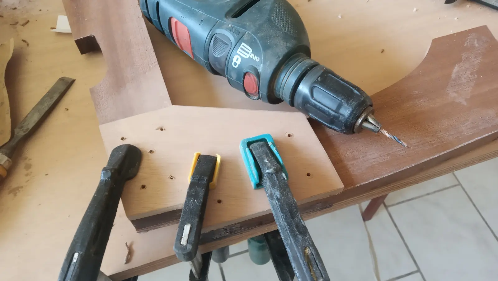
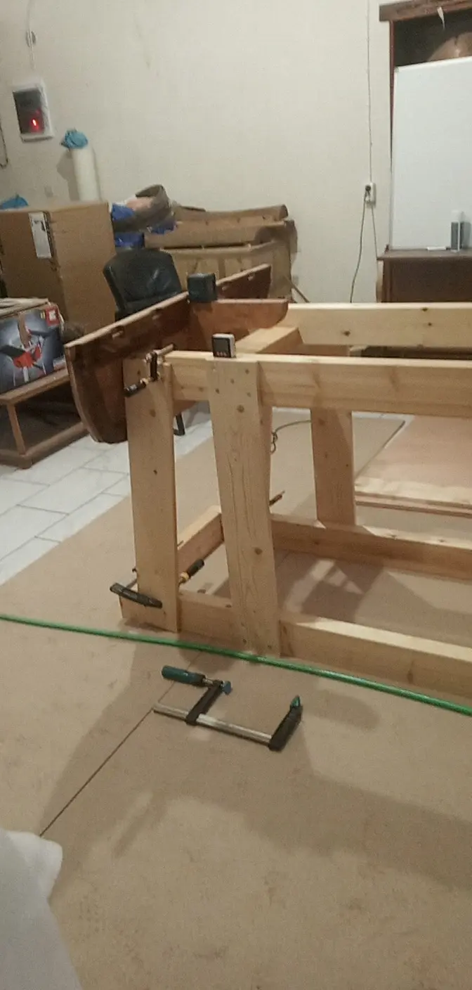
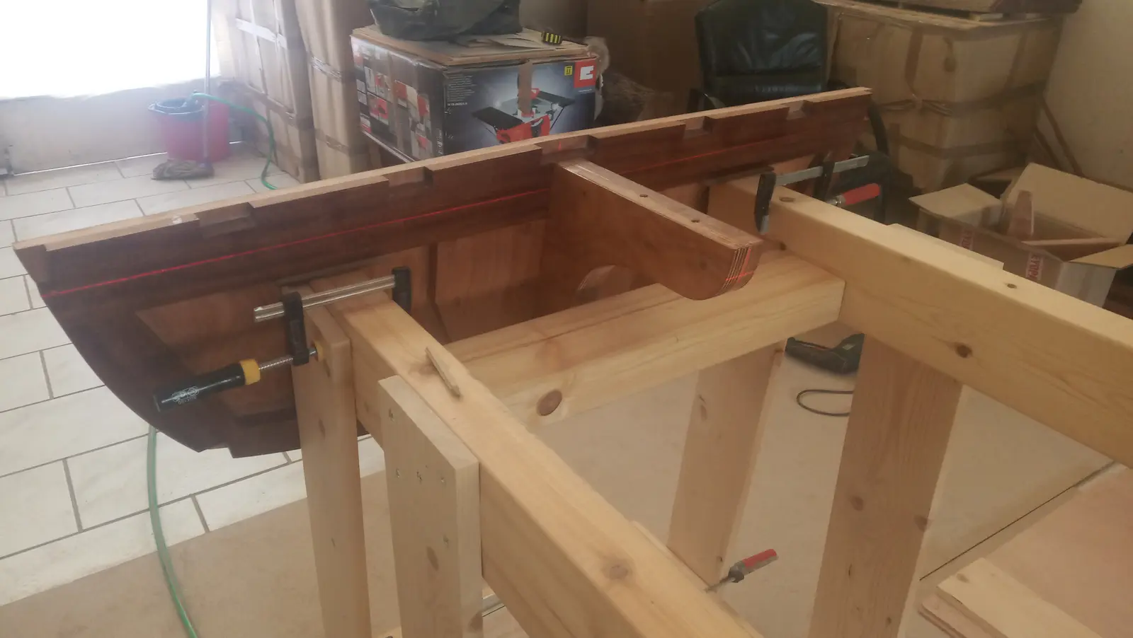
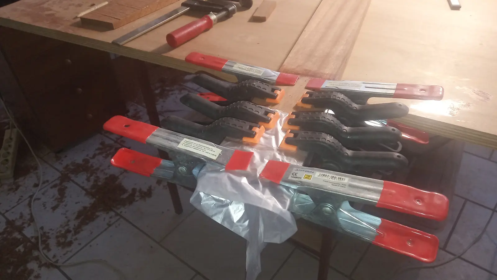
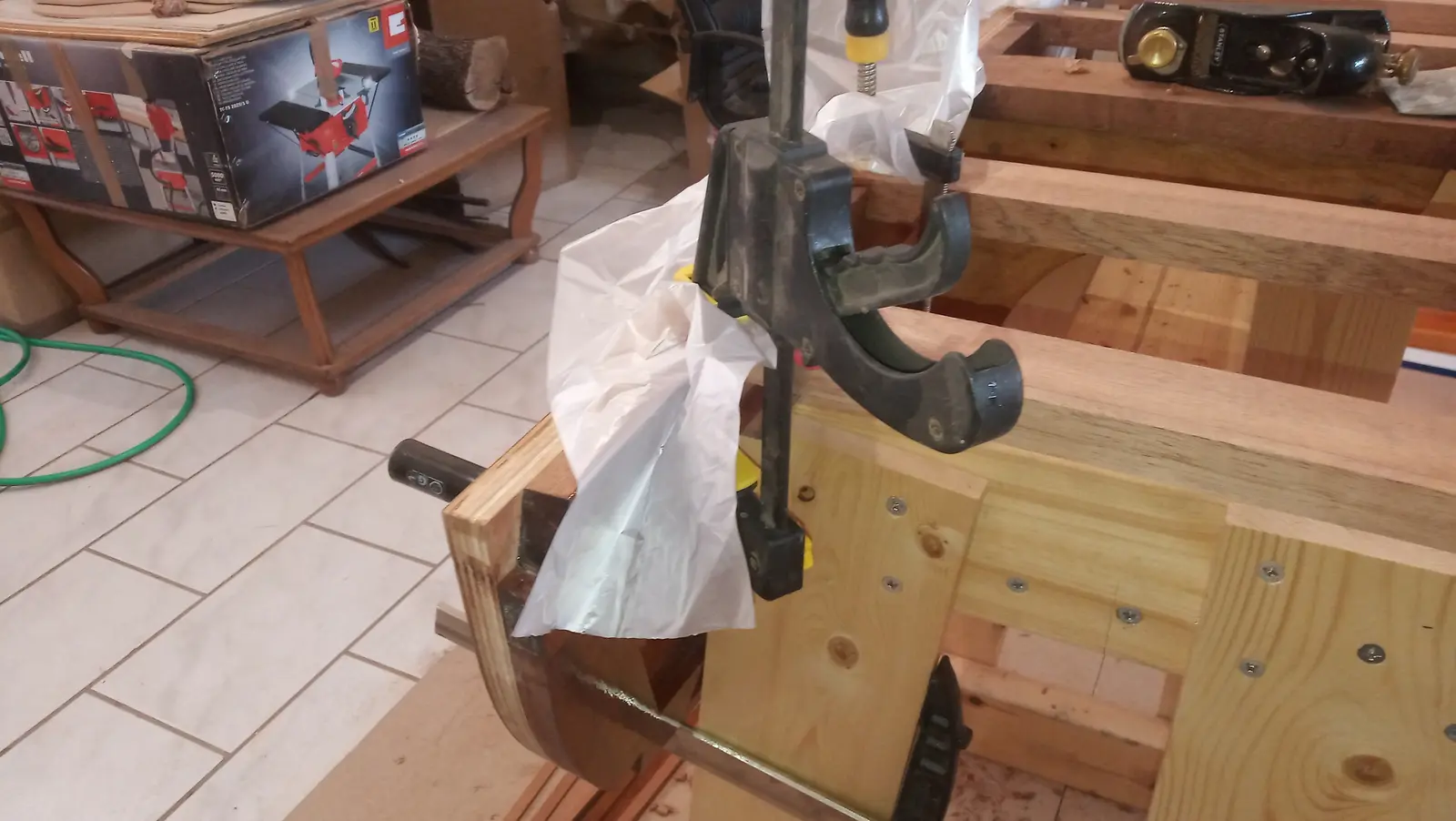
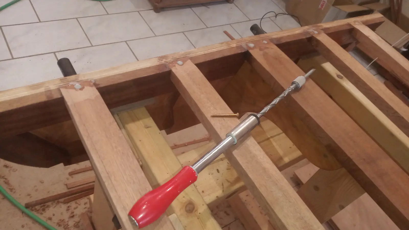
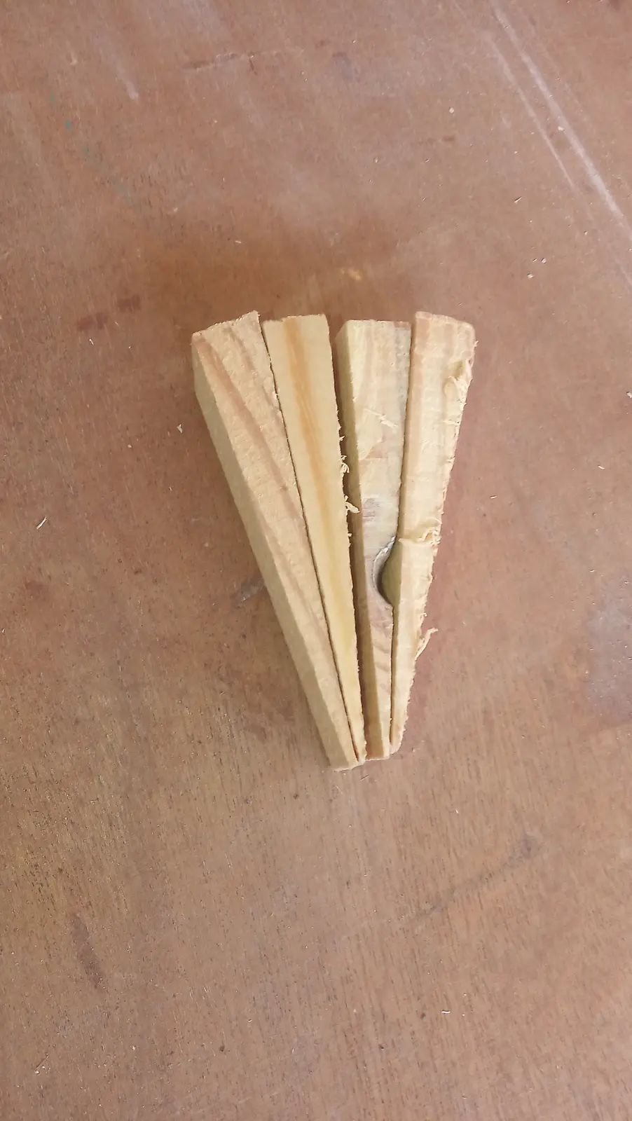
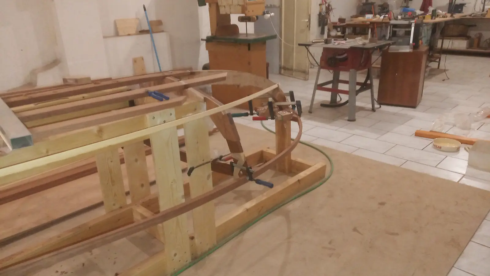
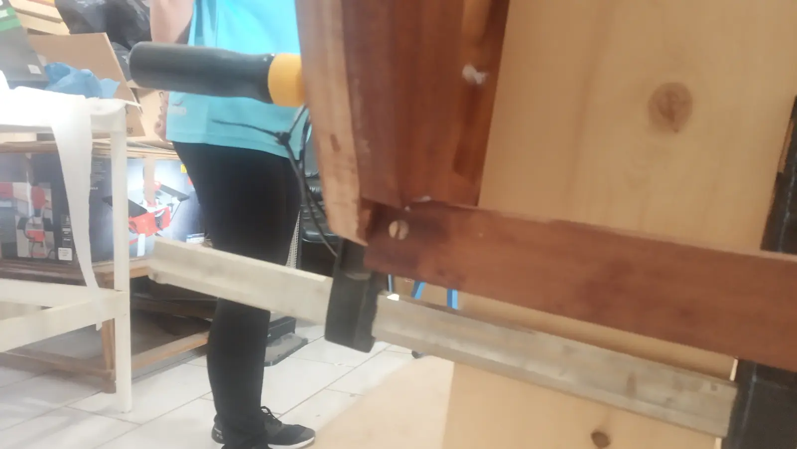
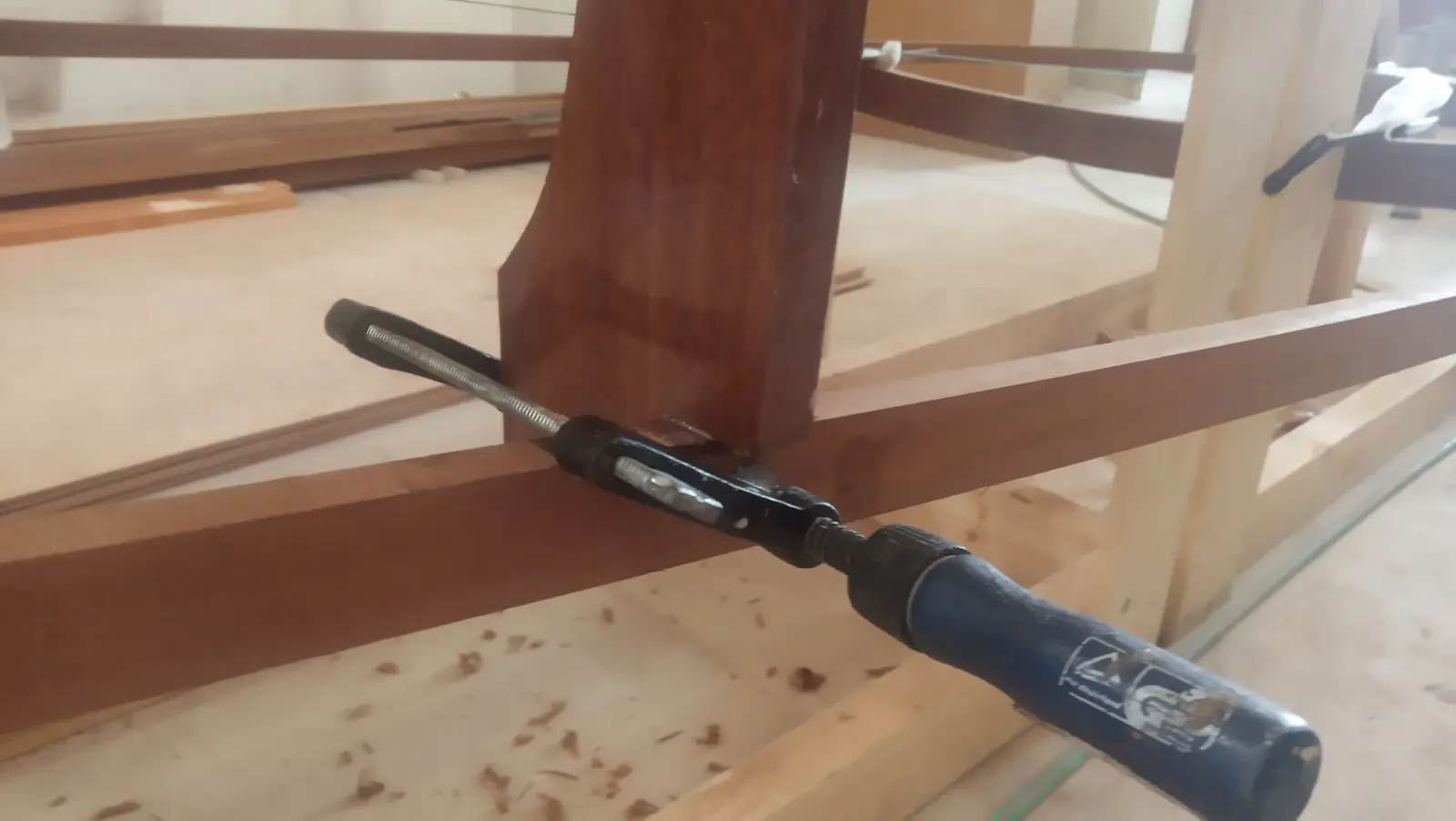
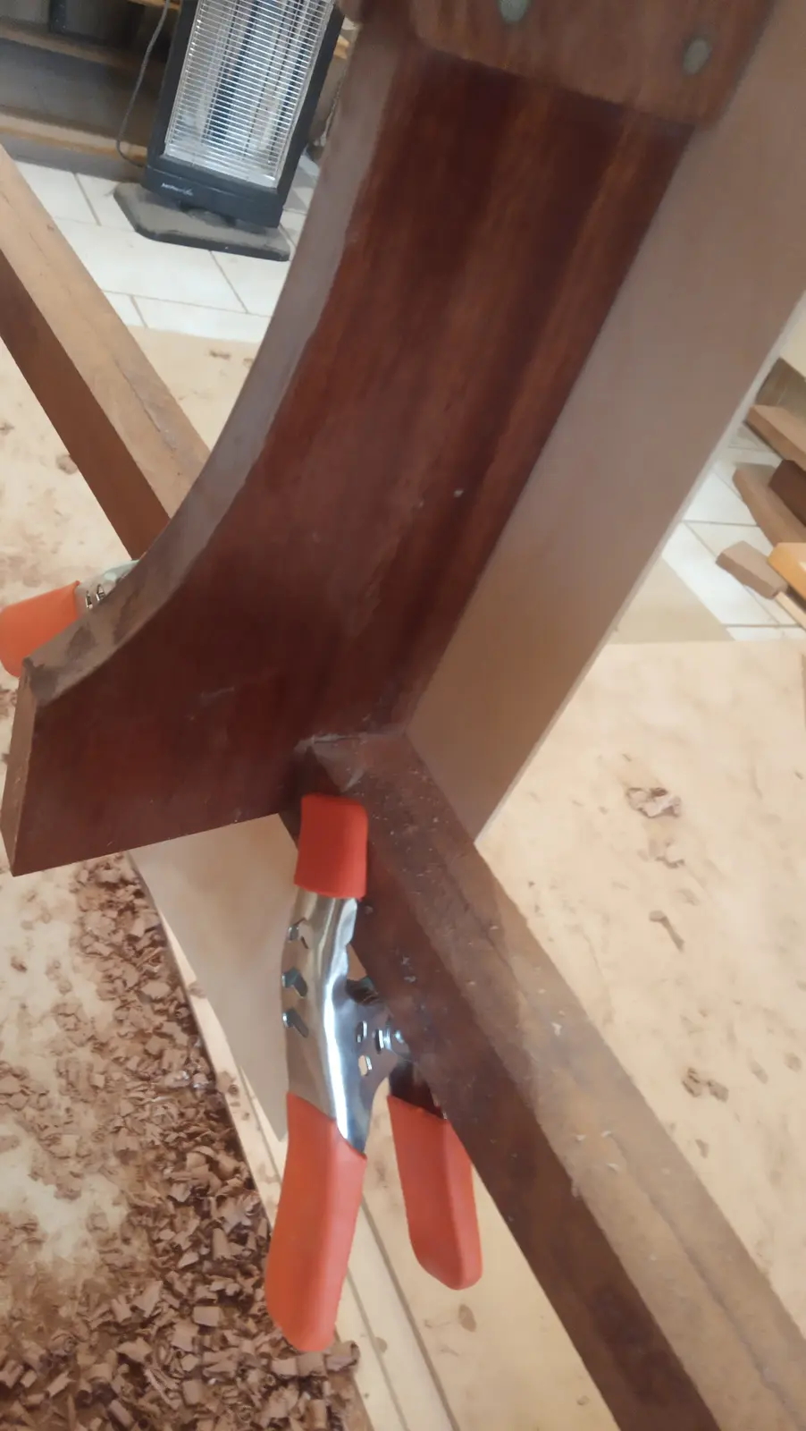
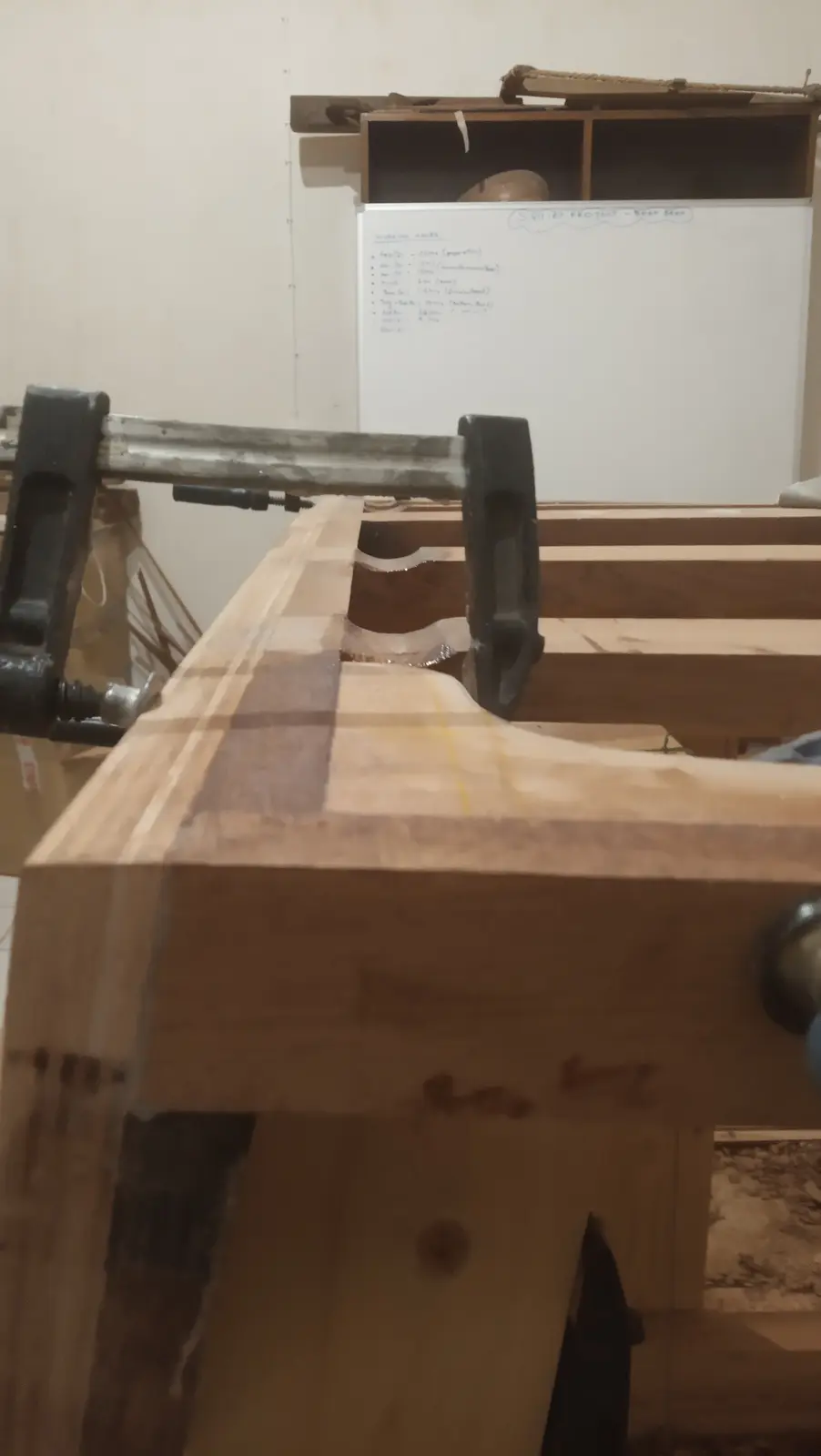
The bending started at the front and worked aft. The day before I had spent a little time working out how the bent timber would be held onto the rest of the boat. I tacked on some wedges so a clamp would have something to grip. In some places it was very easy to get hold of.
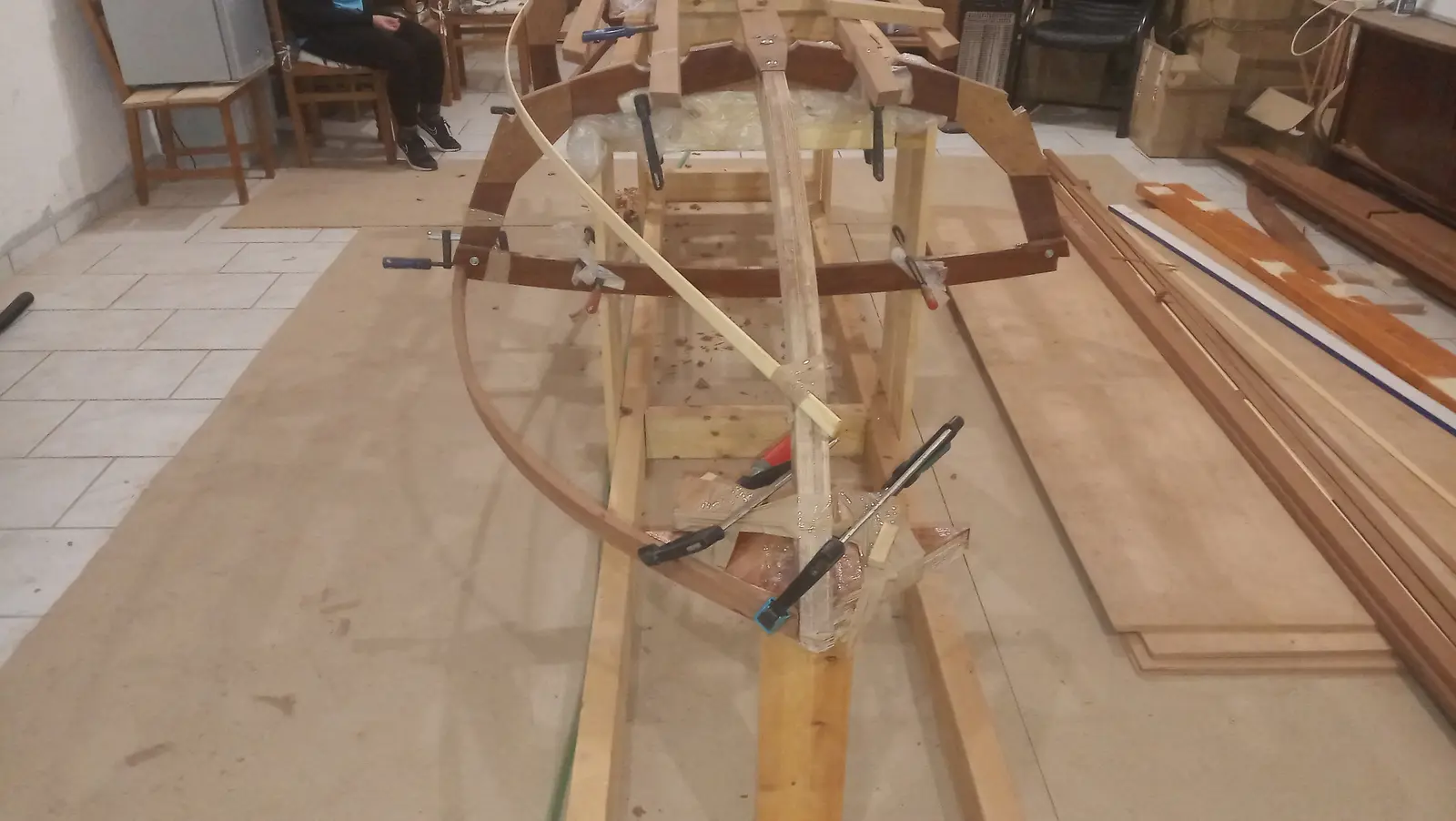
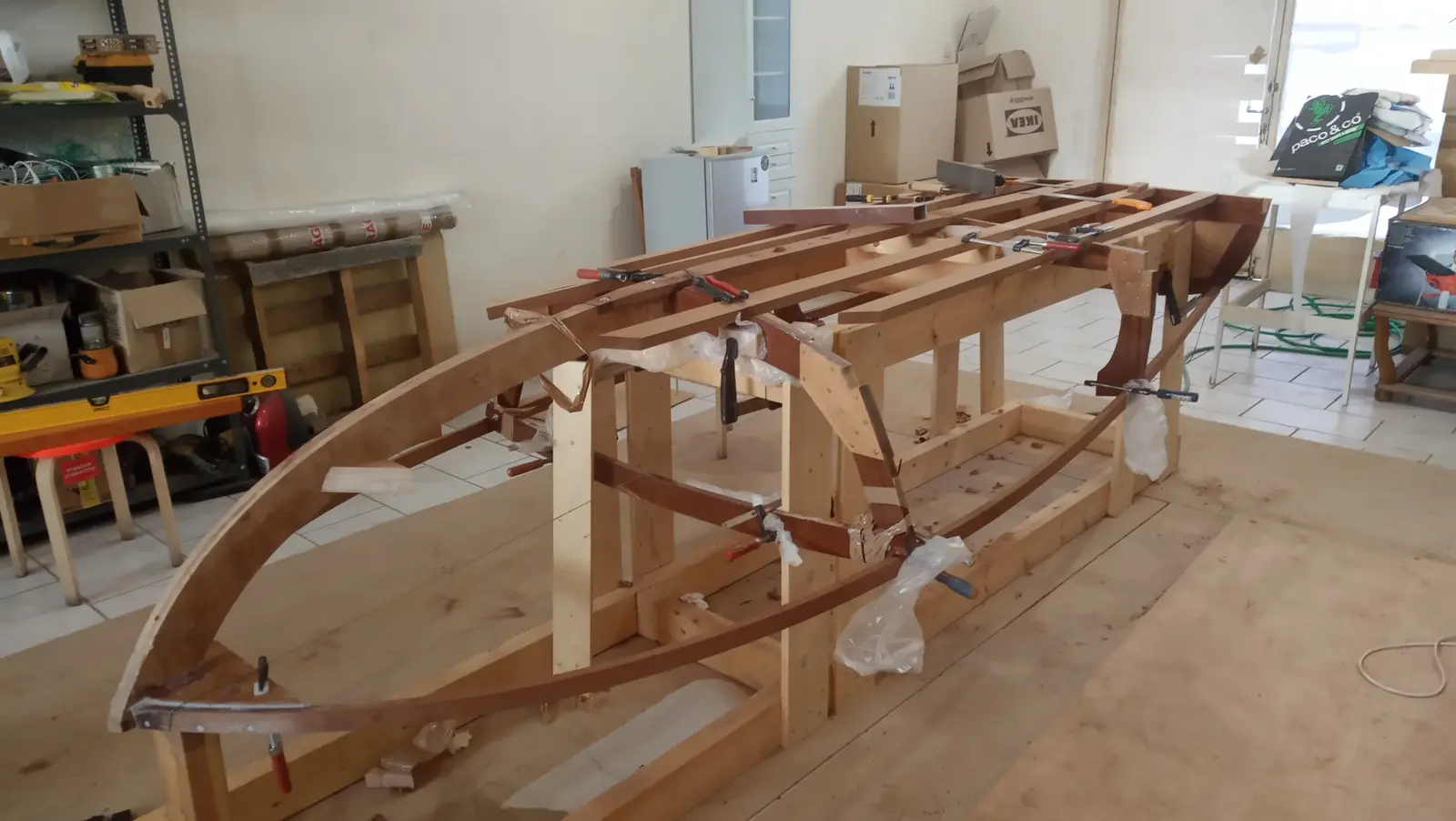
The final result is shown below. I have left the timber slightly long so it can be cut to its exact length later.
A few short videos of the process. Unfortunately there was no way to film the actual bending, as there was nobody else there.
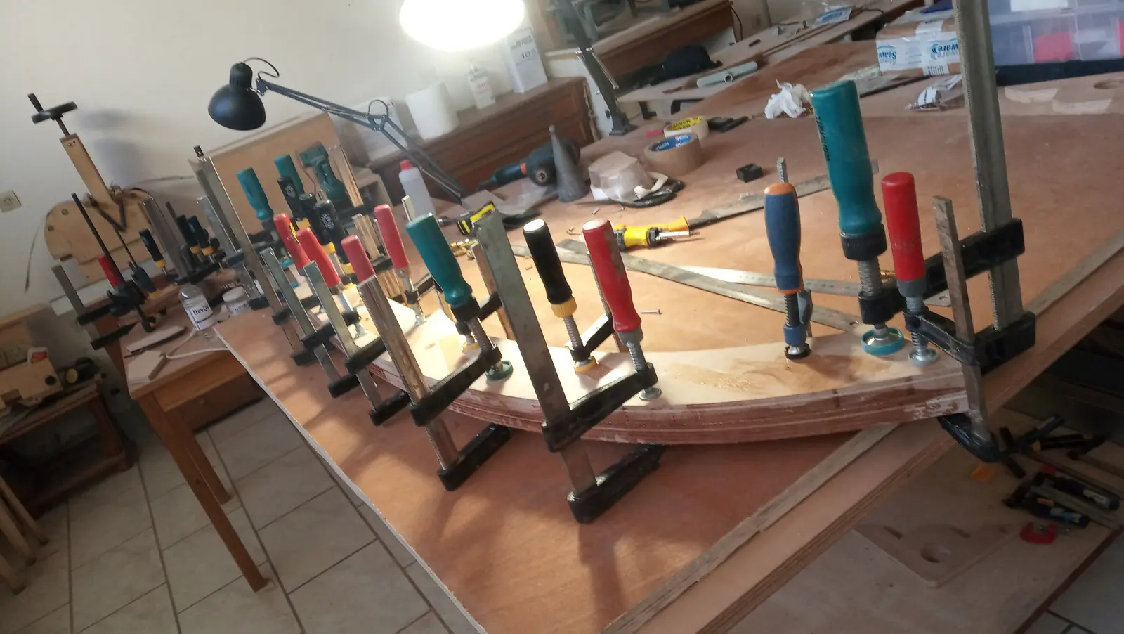
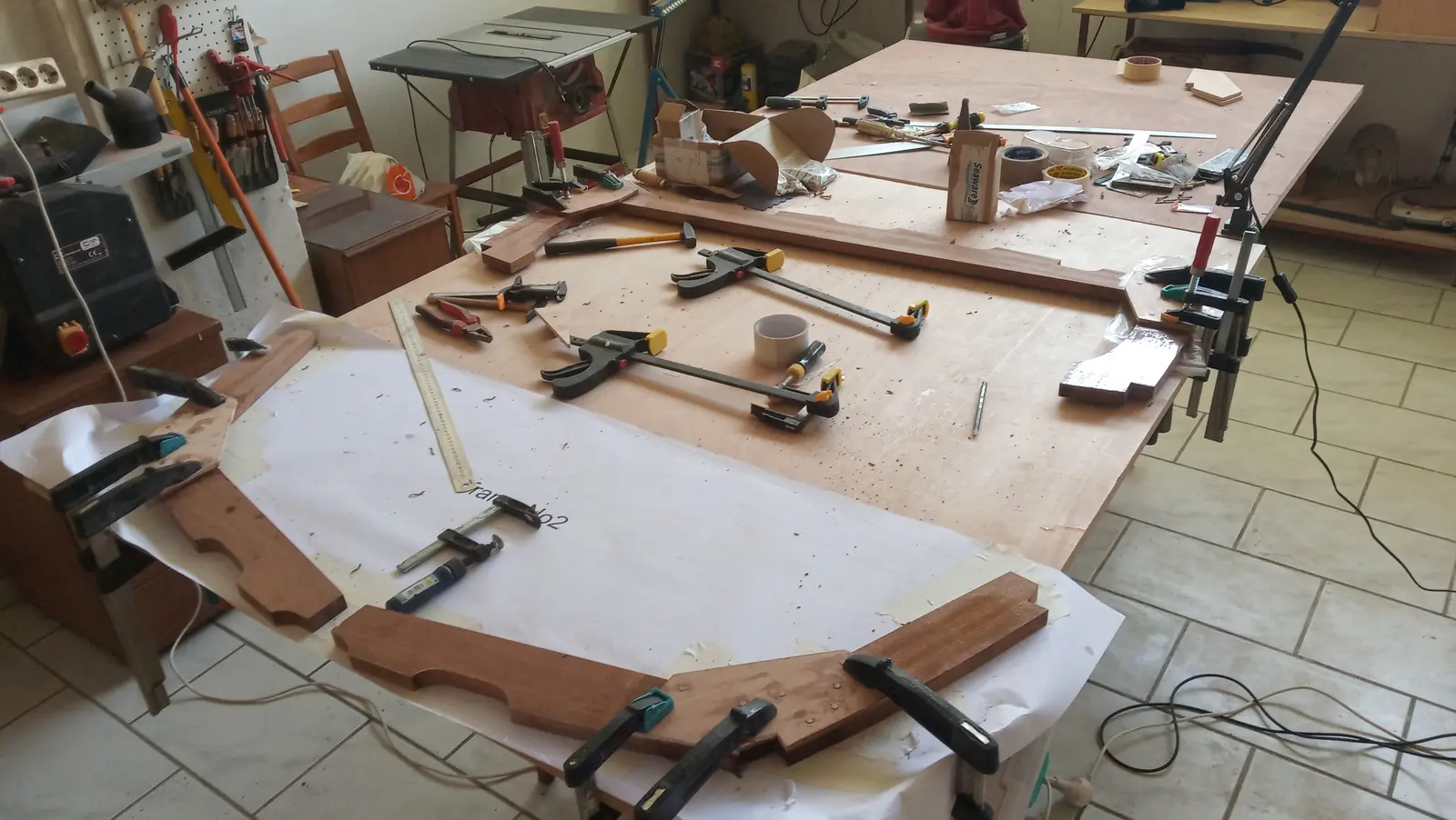
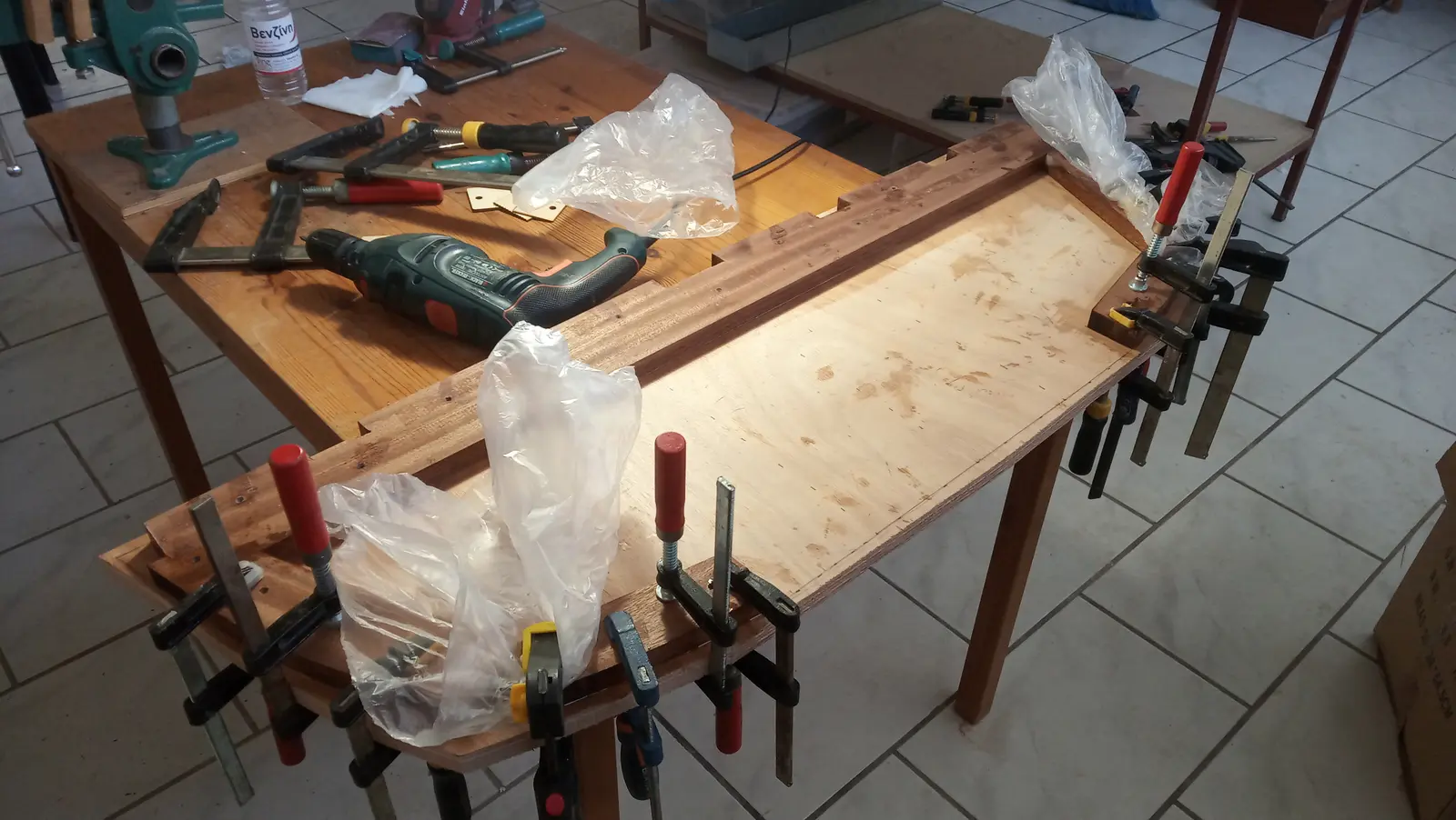
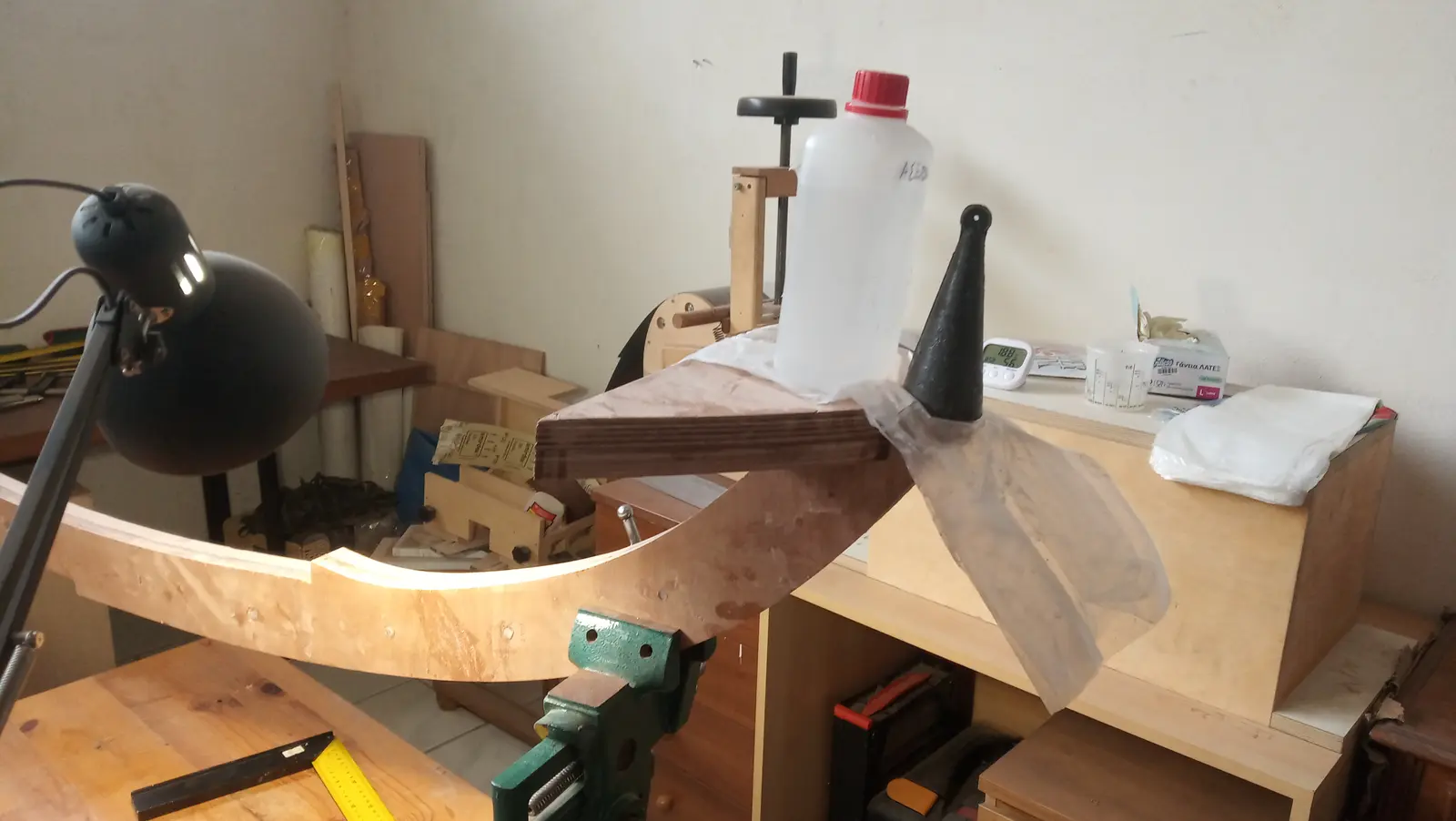
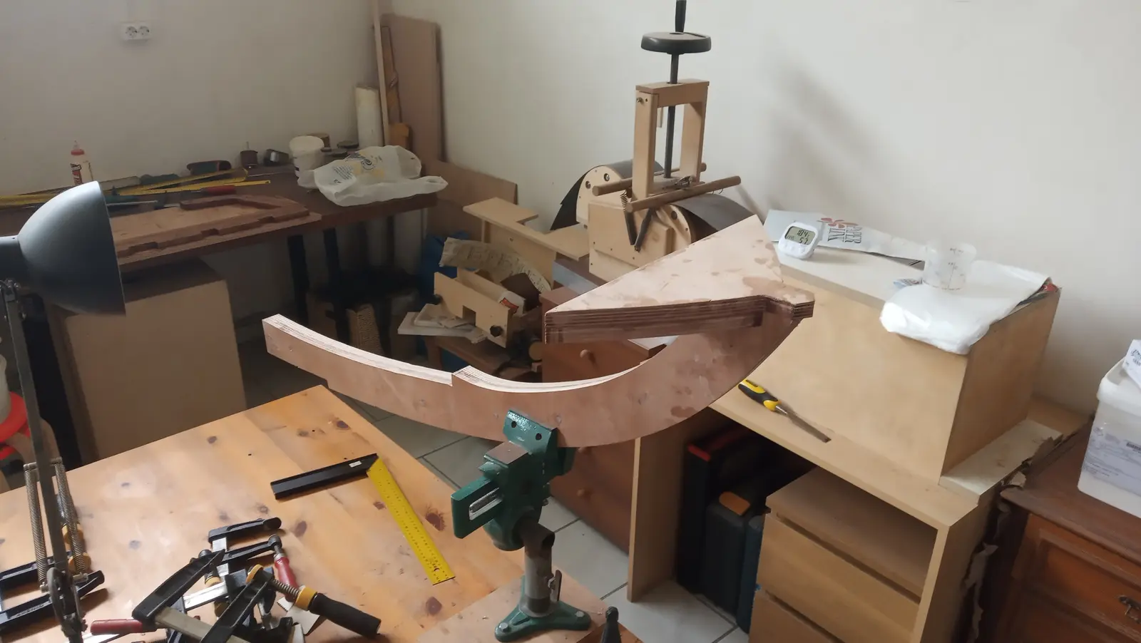
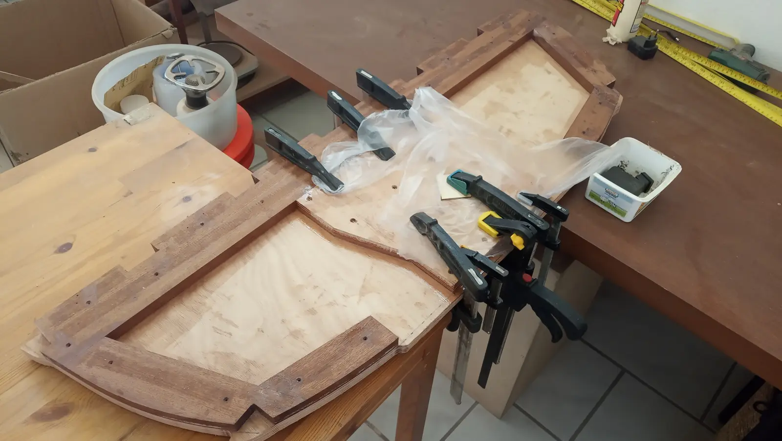
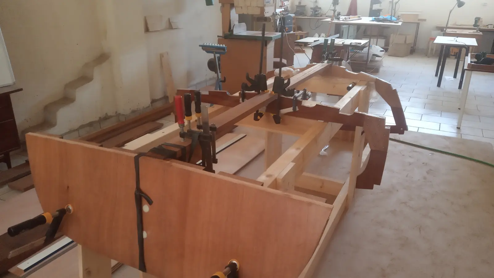
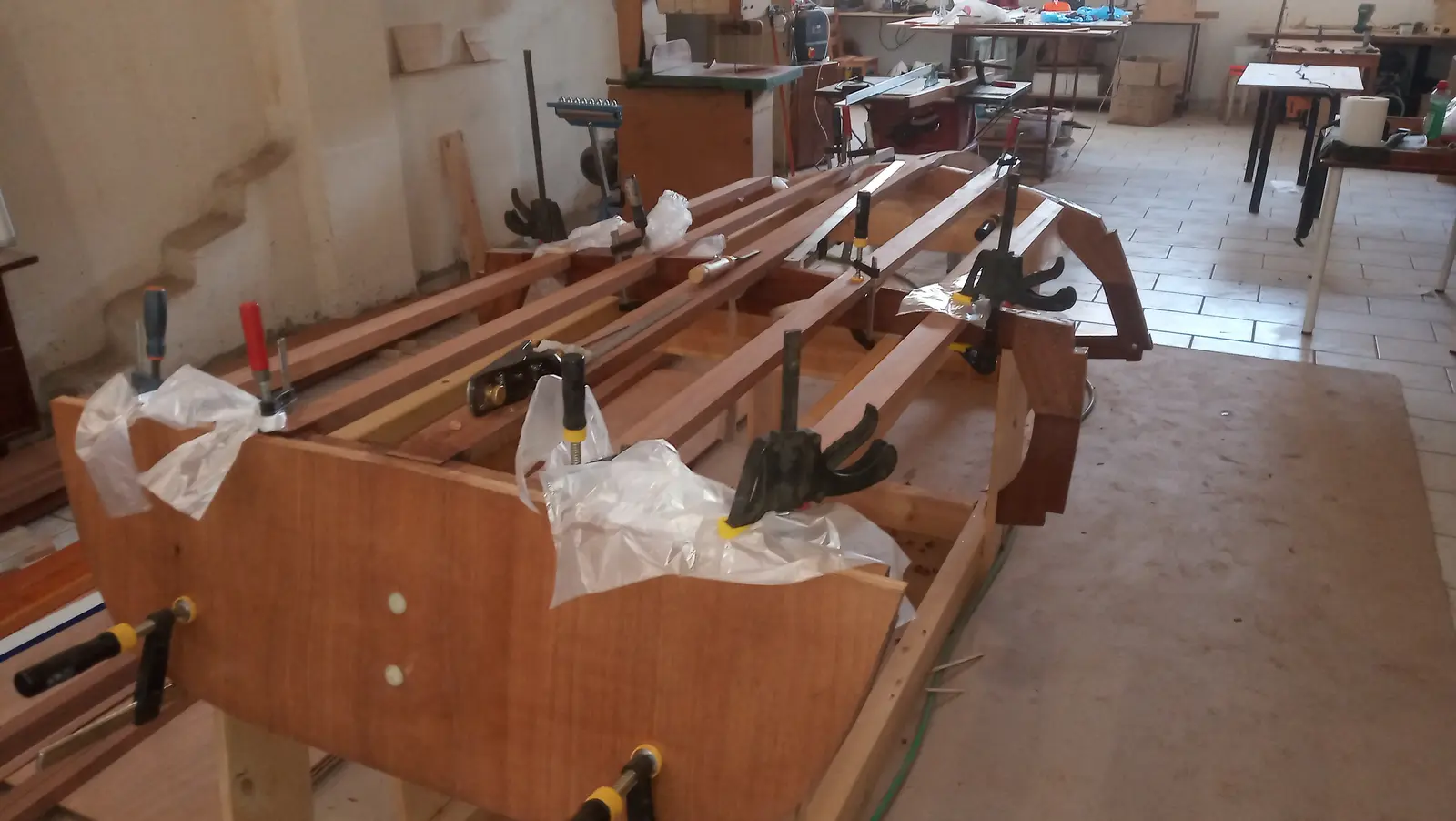
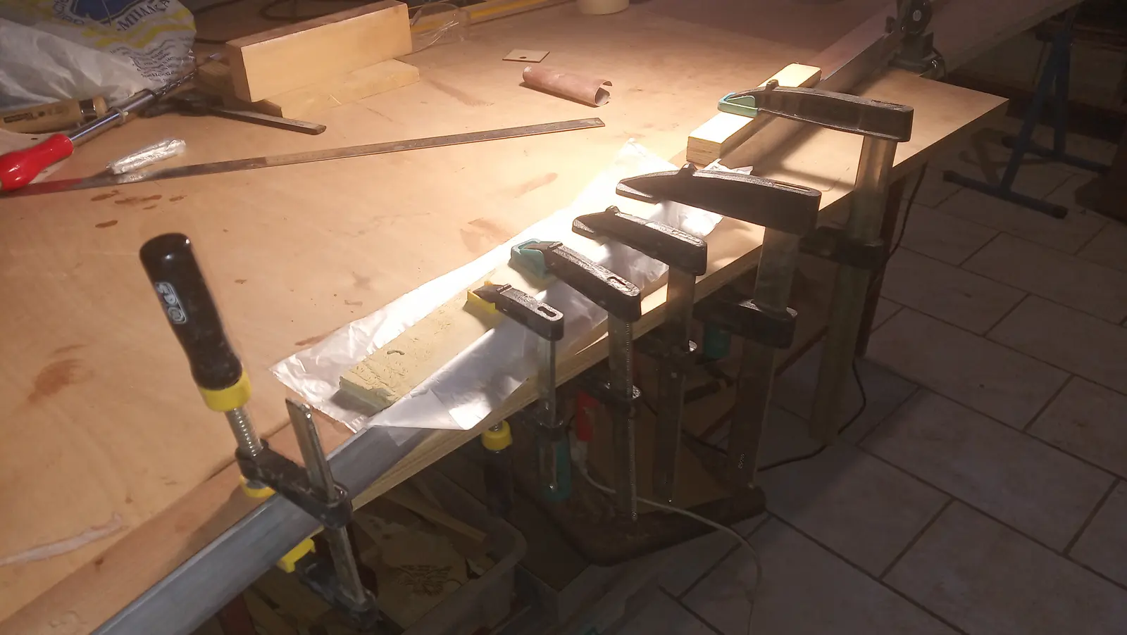
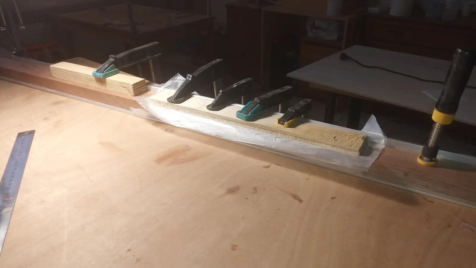
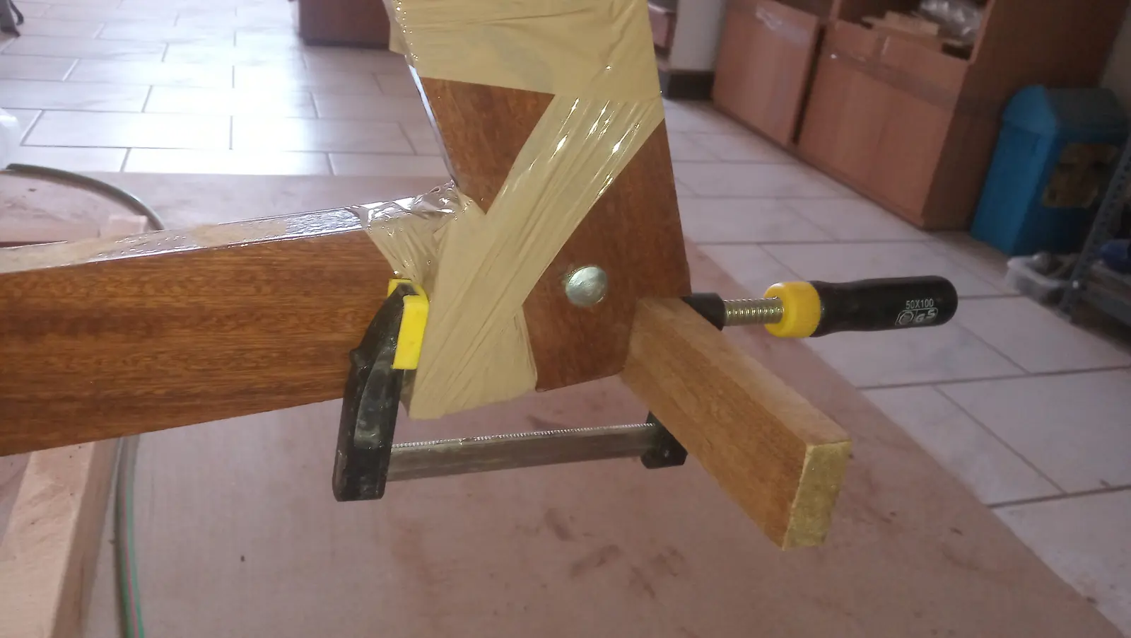
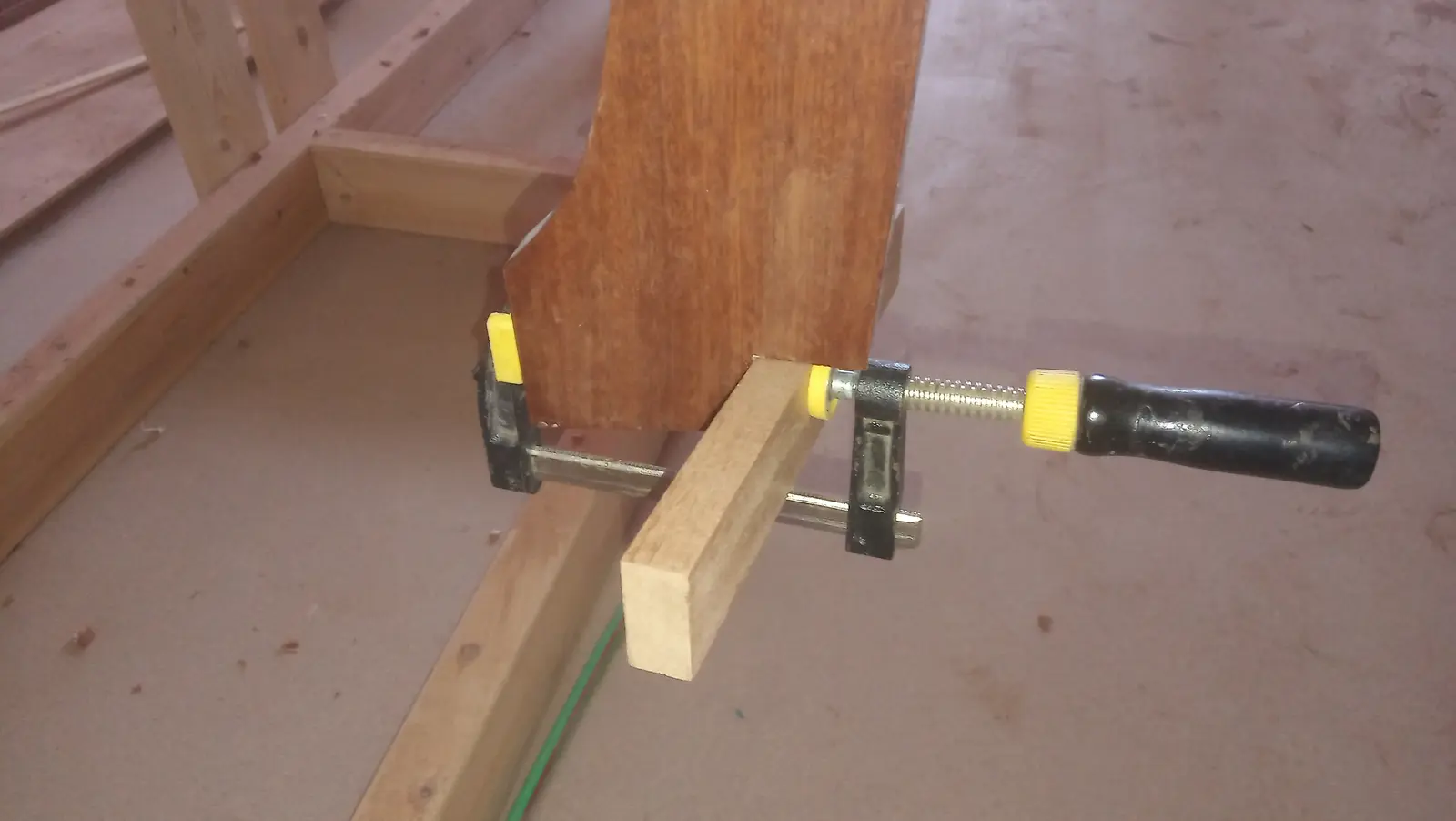
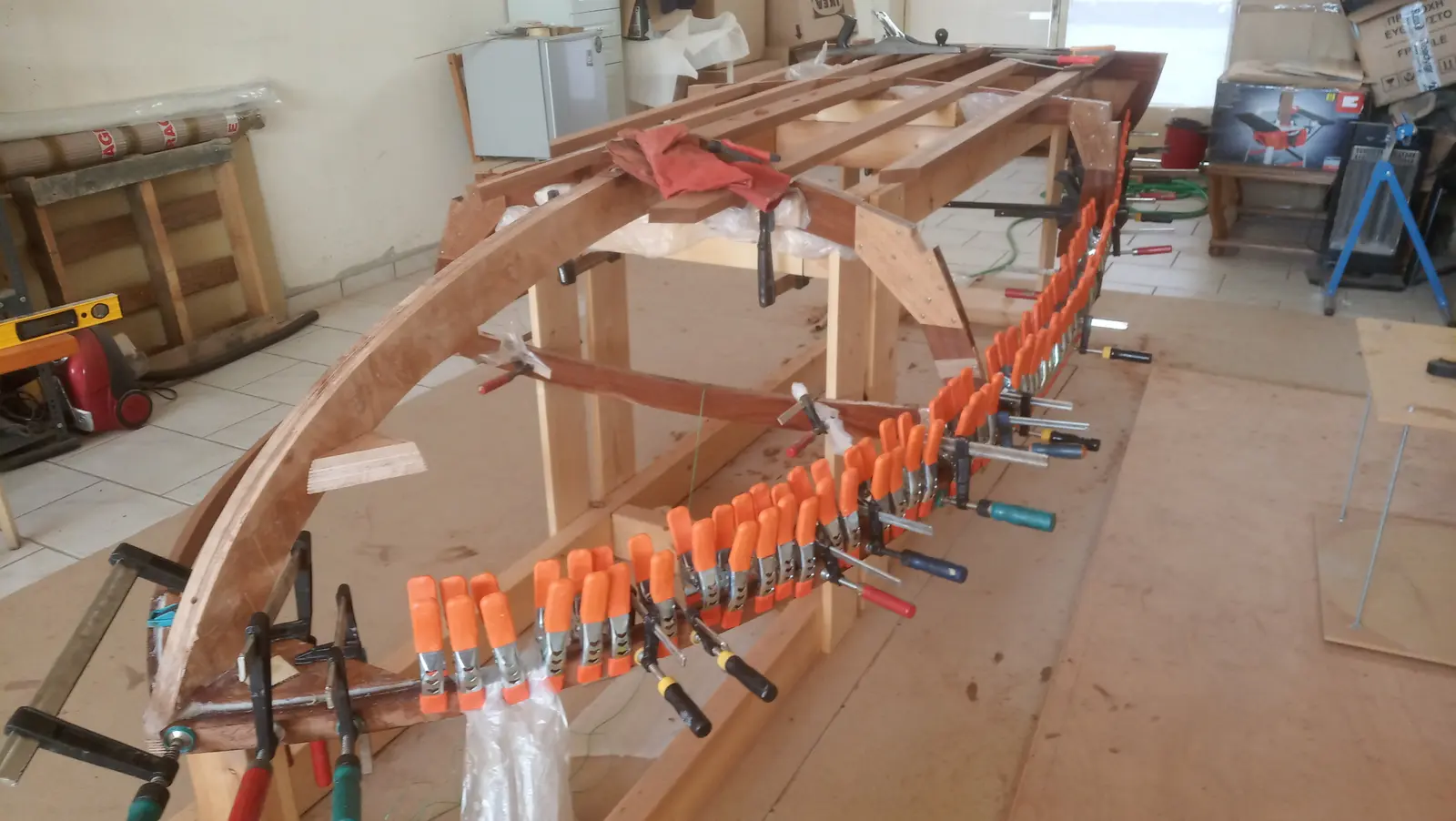
The pieces were left clamped up to dry and take their shape.
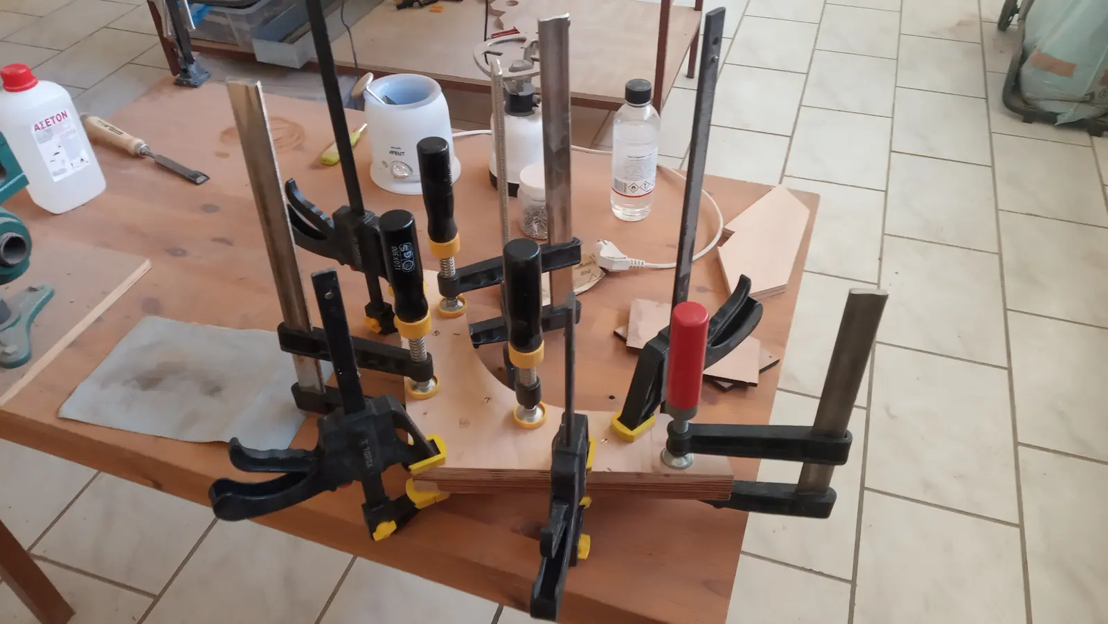
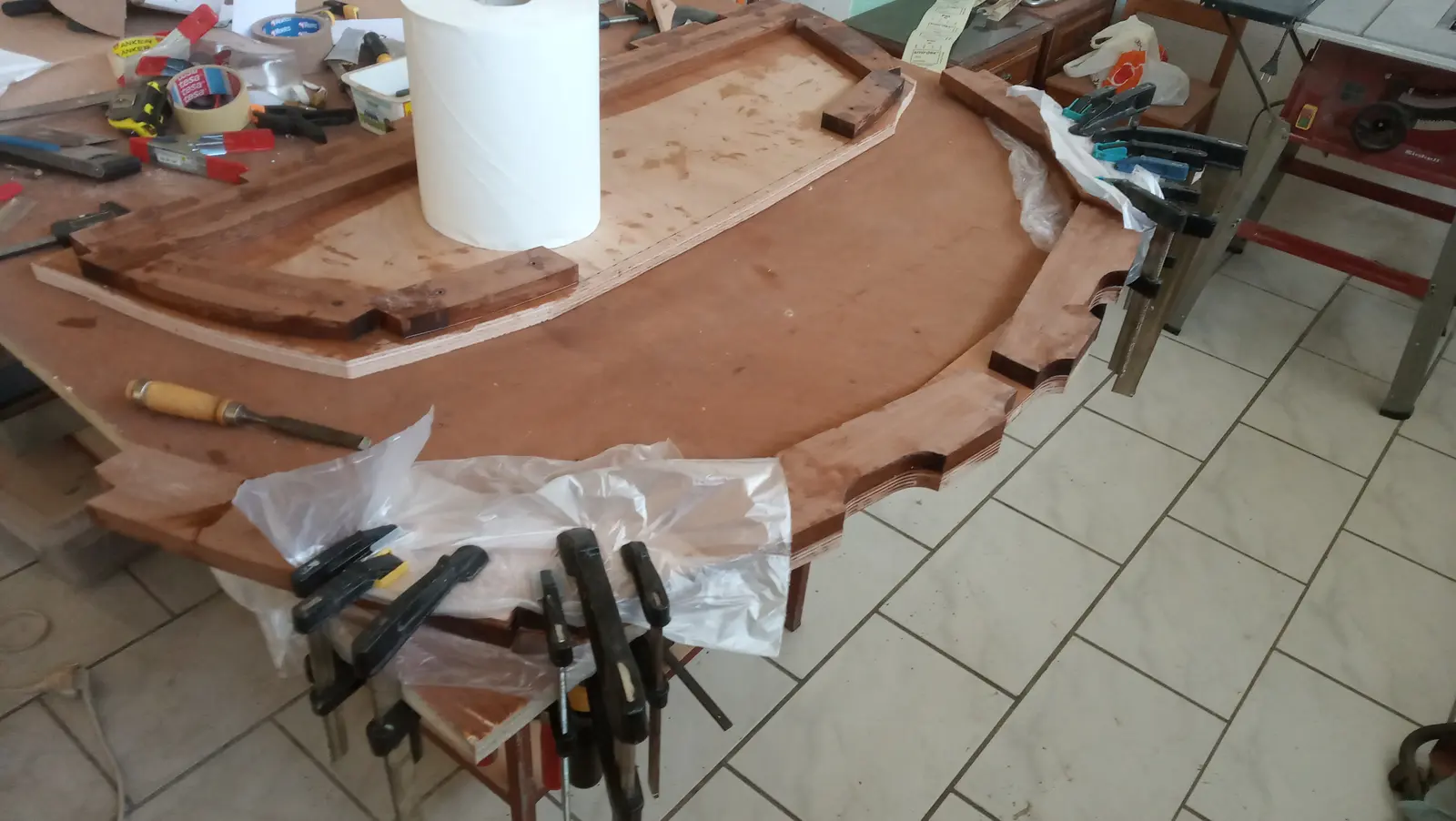
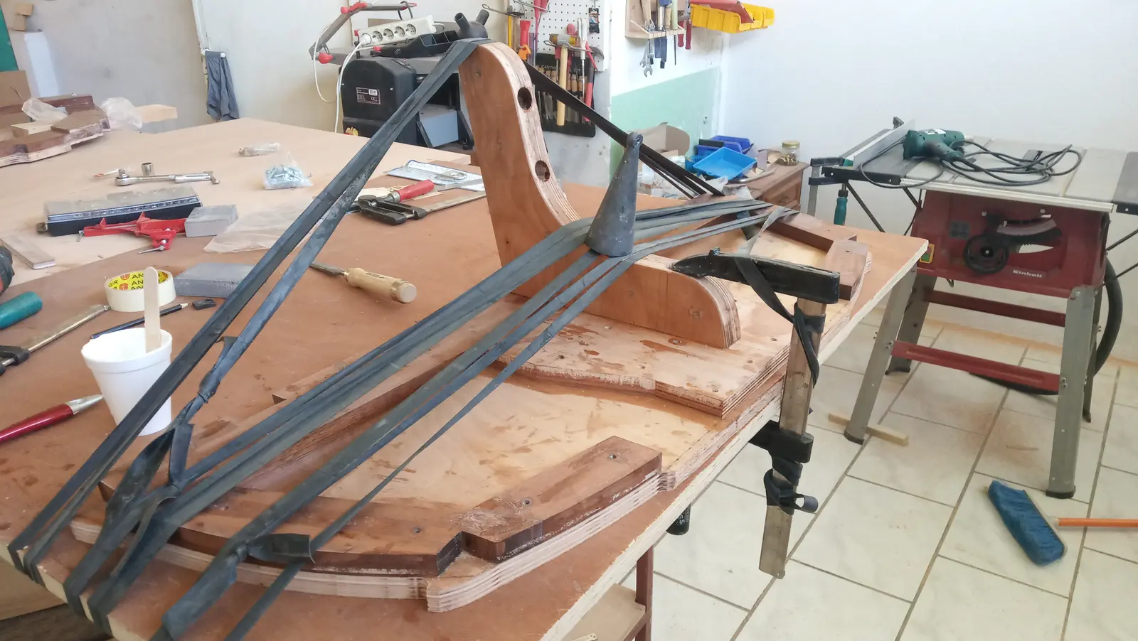
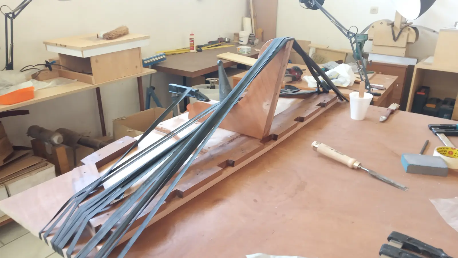
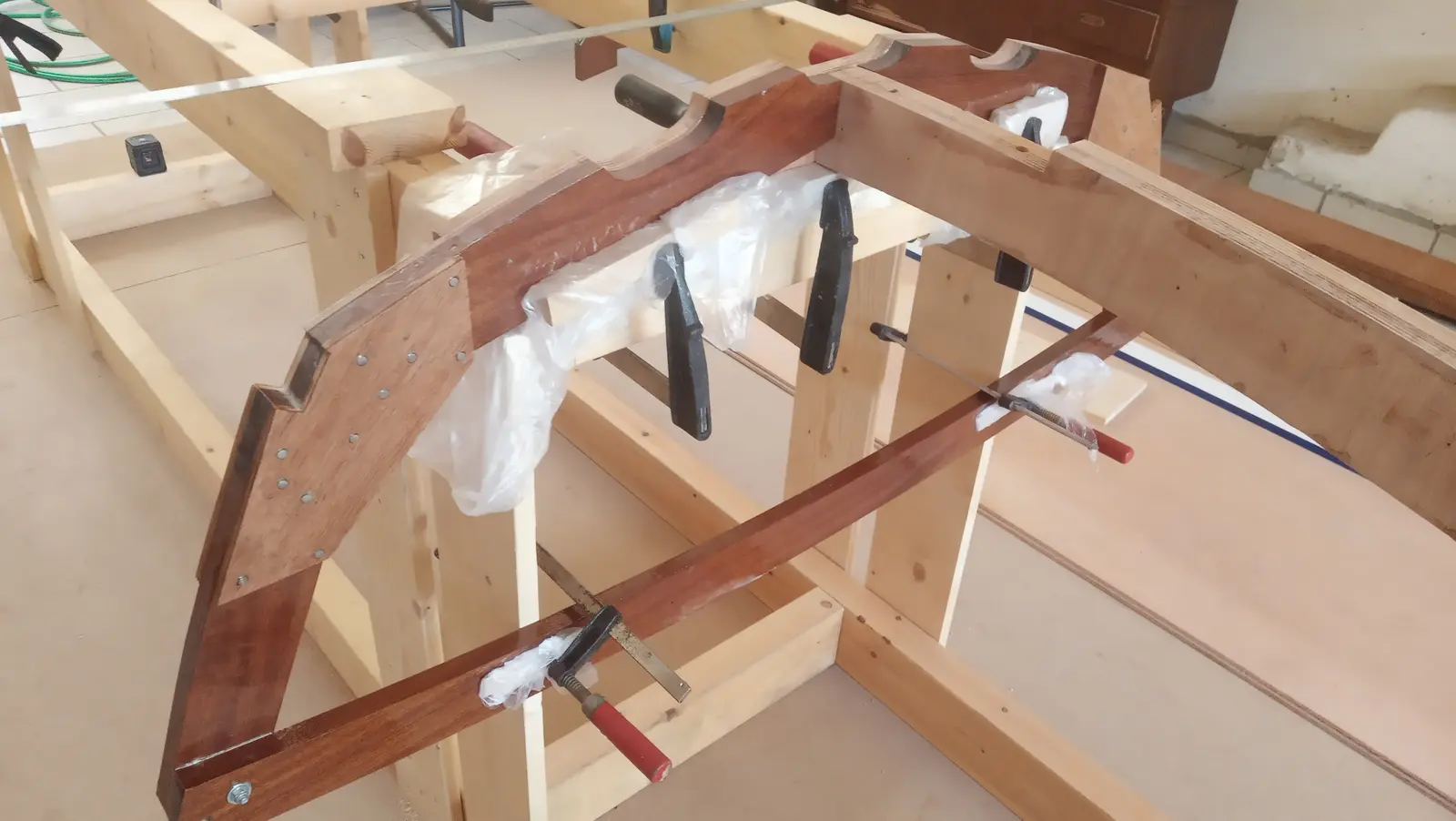
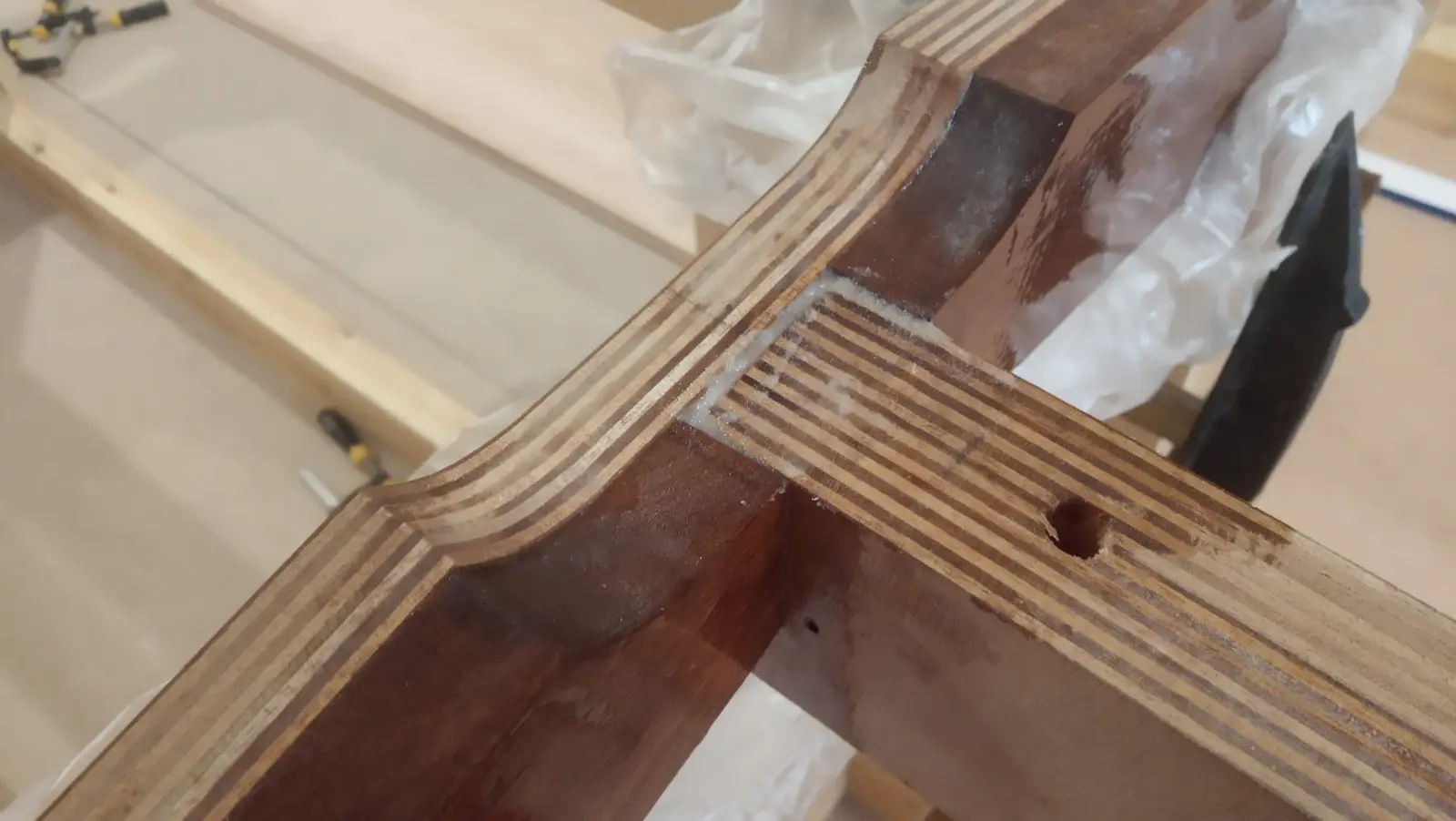
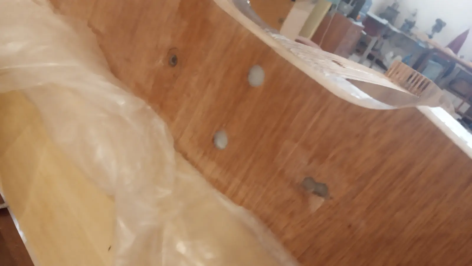
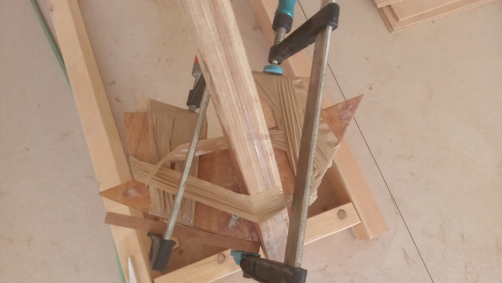
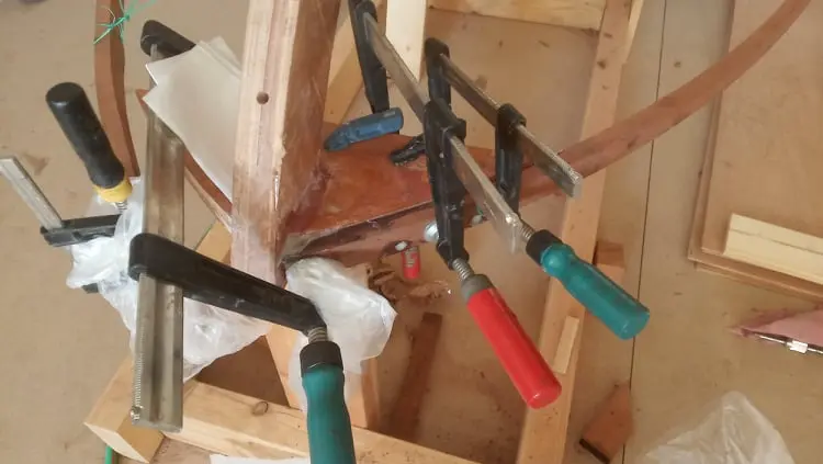
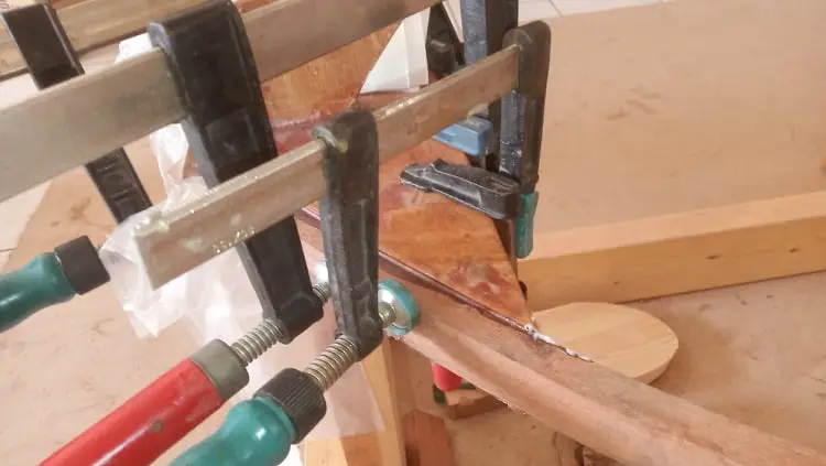
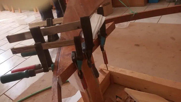
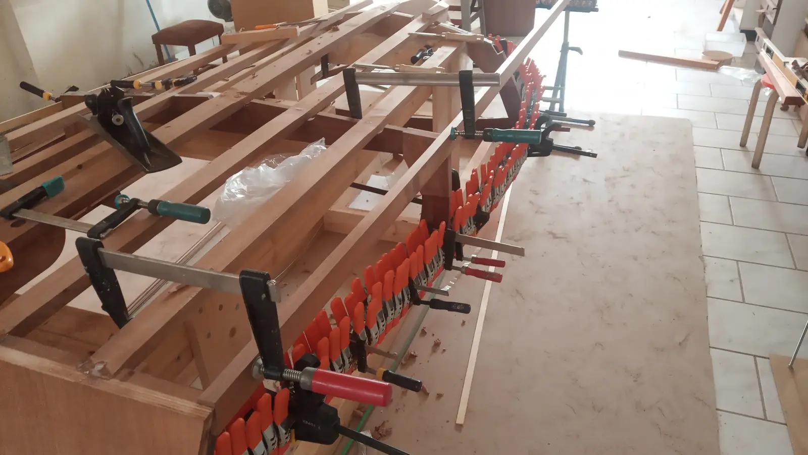
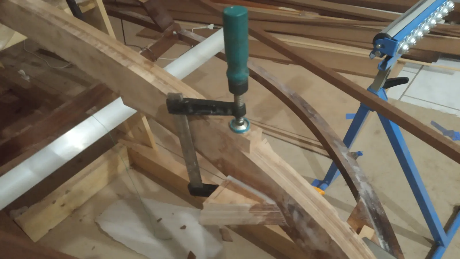
I found that the only way to get them to sit perfectly against the forward face was to clamp them there first, with all the other clamps removed, and twist the timber to follow the imaginary "straight lines" made by the forward triangle. (I tried to bend the forward sections further on their own but could not get a good result.) The forward part was glued first, on both sides. That was so I could make small adjustments and get the structure perfectly symmetrical. Some photographs of that glue-up and of the second attempt at more bending.
They were then glued at the remaining joints on the frames and the transom.
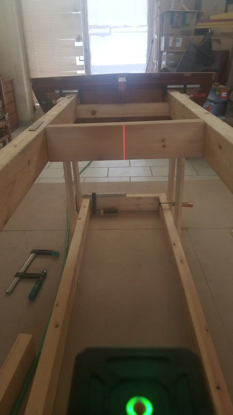
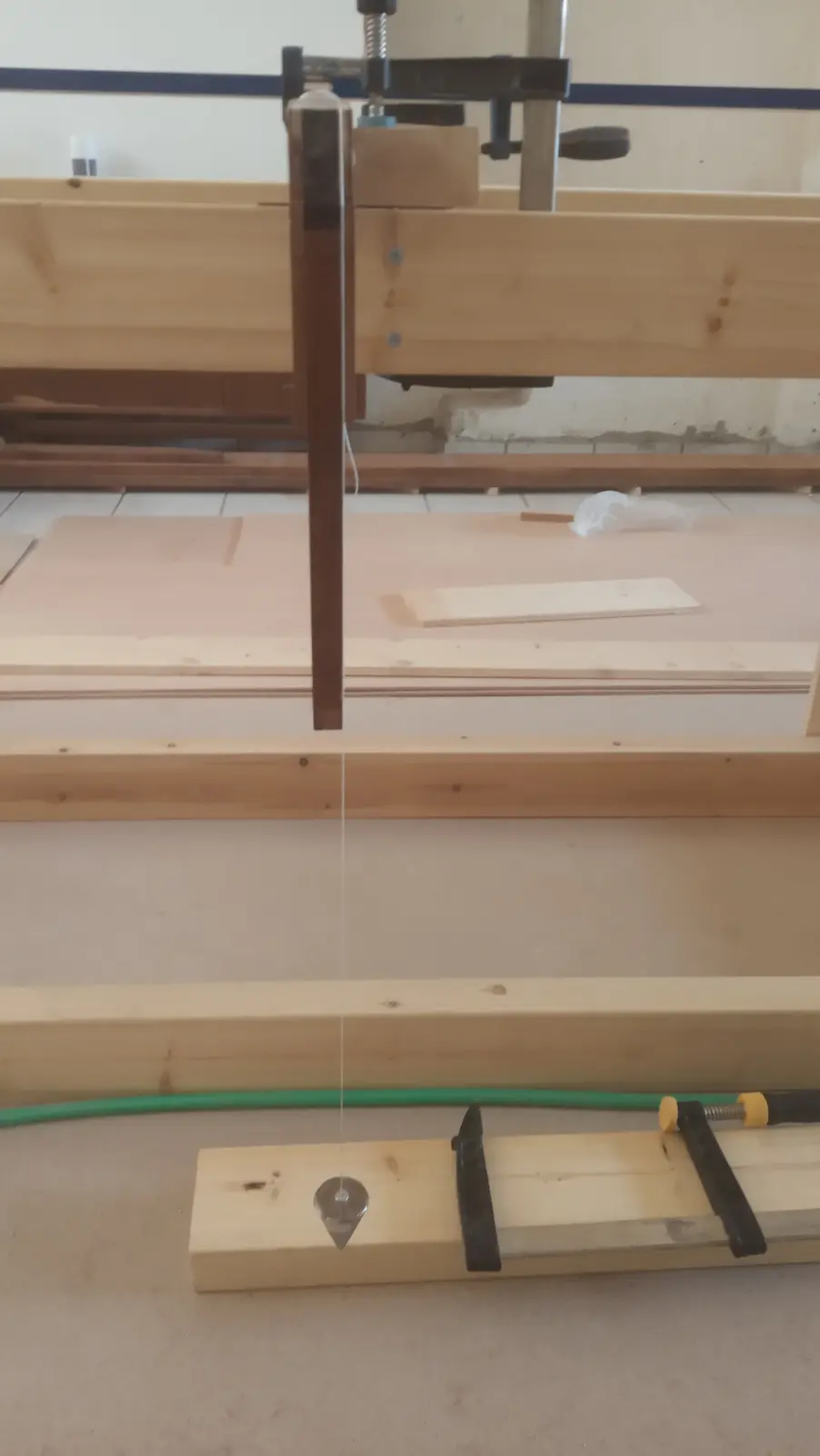
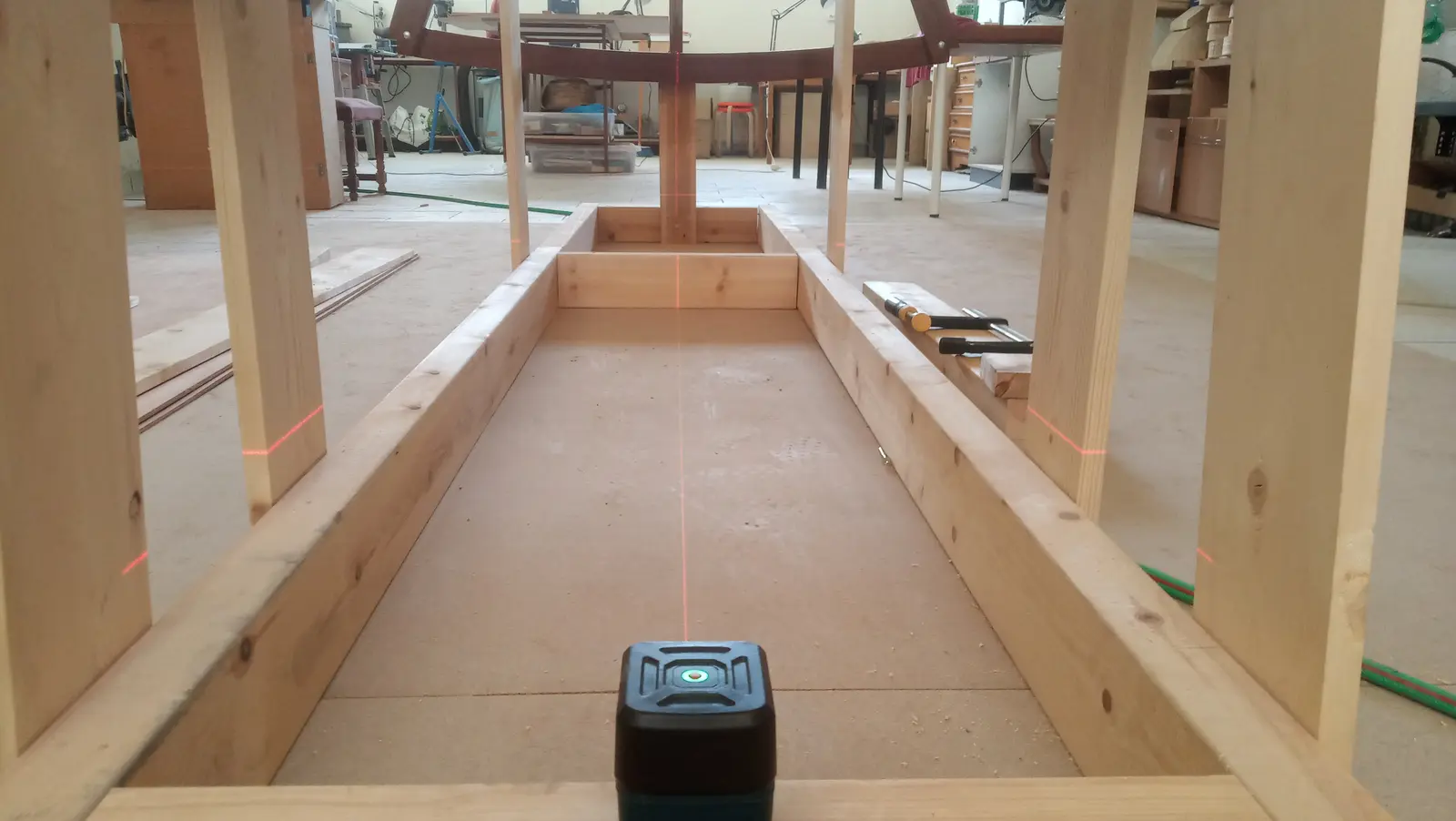
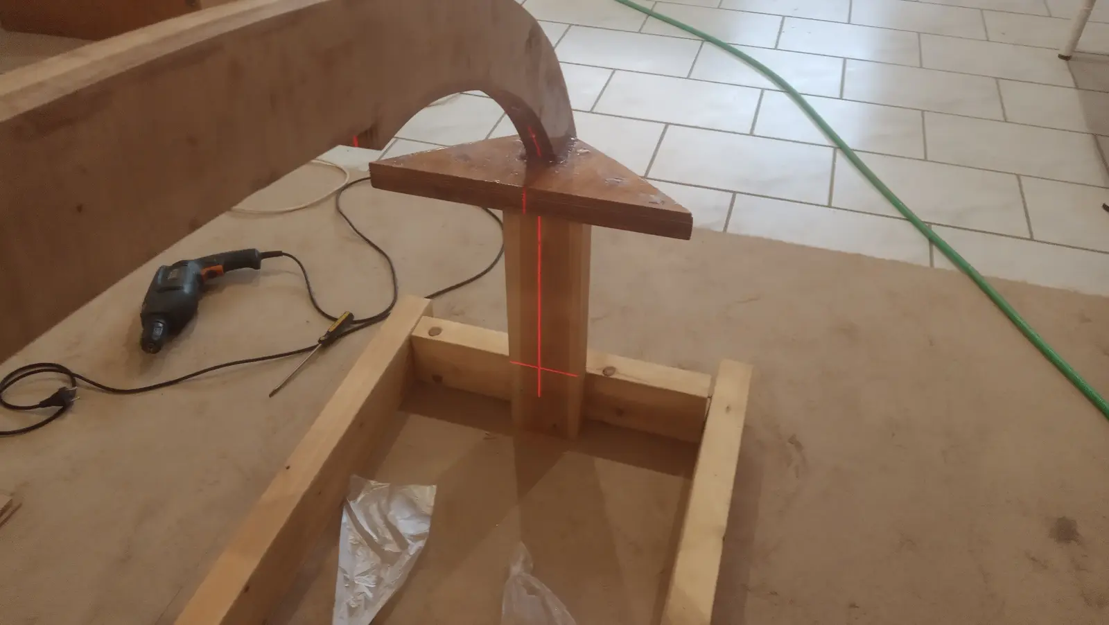
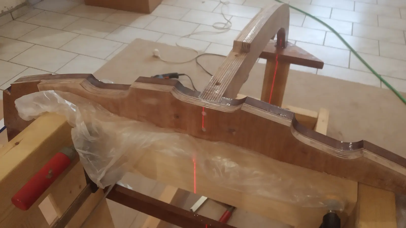
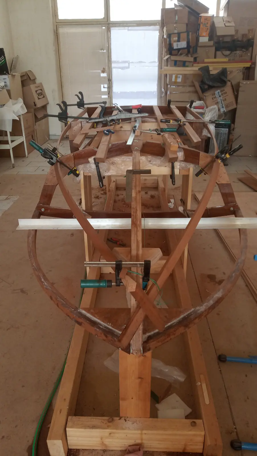
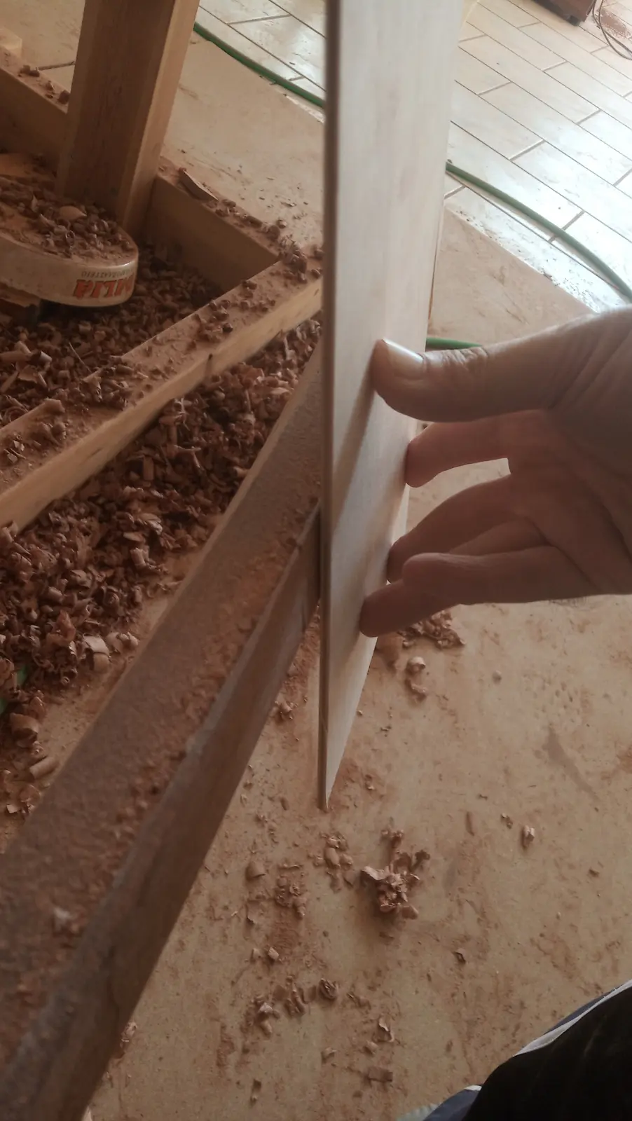
Before gluing at the forward frame they were tacked in place so I could check the two curved pieces were symmetrical. Using a string line I pulled the centreline that splits the boat down the middle. Checking it, I found it is almost symmetrical about that axis (it is out by one or two millimetres, and those get corrected when the timbers are faired) but there is a problem on the z axis. One piece, even though it was glued exactly the same way as the other, sits closer to the floor. The difference runs from zero (at the frame and at the triangle forward, obviously) to around 7 millimetres somewhere near the middle. It is a serious problem, because when the timbers are faired they are cut at an angle and end up triangular. If one is at a lower level then in the end we will have a deck that is not symmetrical. Say by a centimetre, but it will show because of the shape of the final pieces with the stripes.
Once I have glued the second run of timber I will try to fair them on all three axes, measuring the distance from the floor and from the centreline every so often (every 15 or 20 cm). If fairing takes more wood off the low side then a third piece will have to be glued on top to build it back up.
Once that is done I will start fairing for the plywood to be glued on.
There is another solution that corrects the problem visually, which will be used if the above does not go well. Essentially, if it does not come out symmetrical in the end, the plywood and the striped timbers on the top are glued perfectly symmetrically and a wooden fillet is run underneath, around the perimeter. Where the plywood overhangs, the fillet is left slightly thicker. I will explain it better if the problem actually shows up (it has shown up for most people who have built this boat, and I do not expect to get away with it even though I know about it).
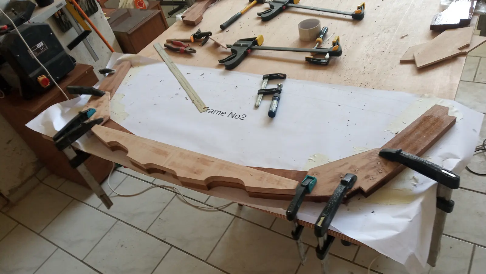
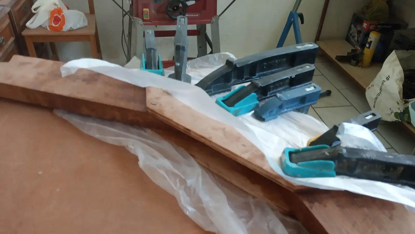
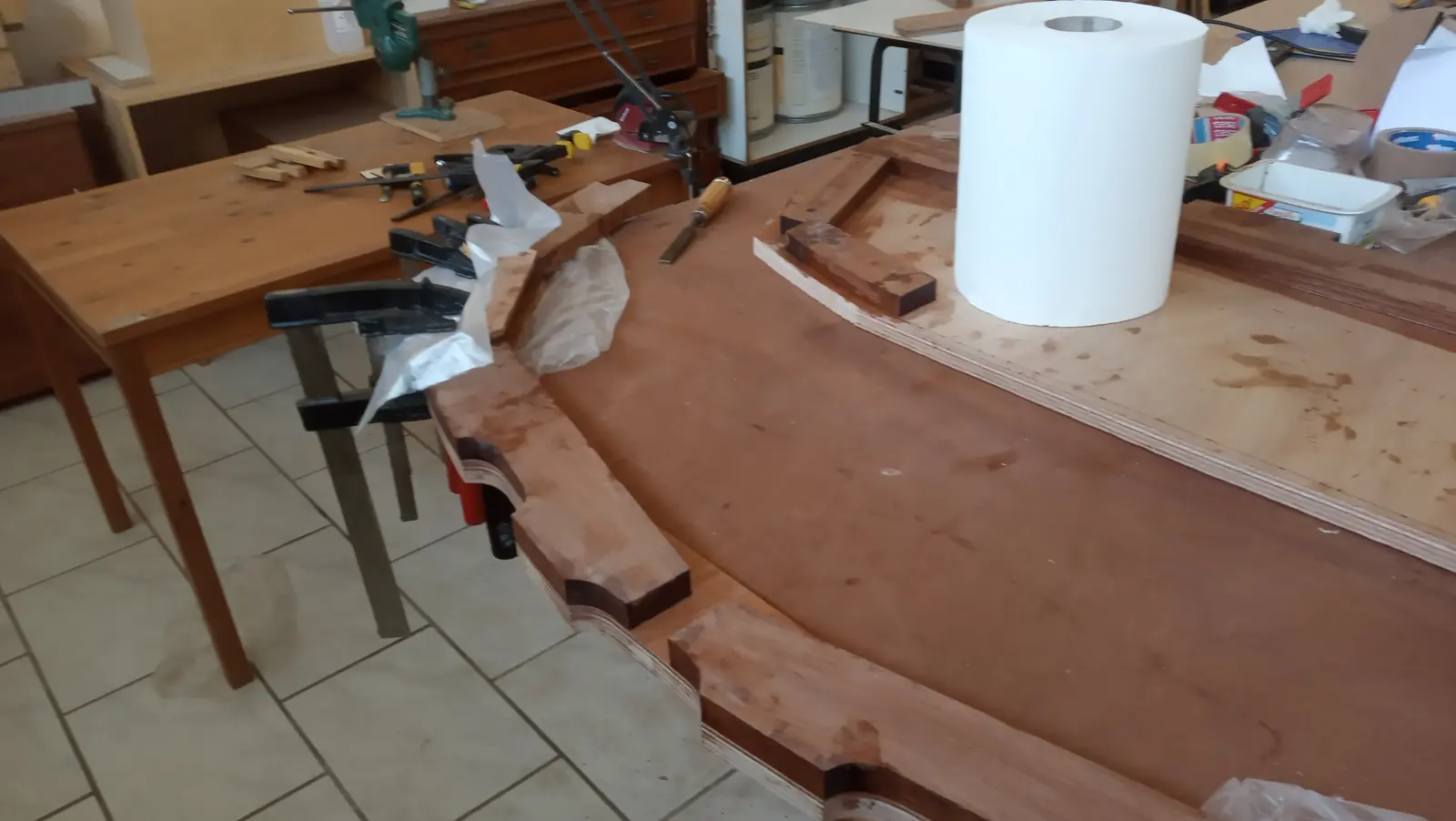
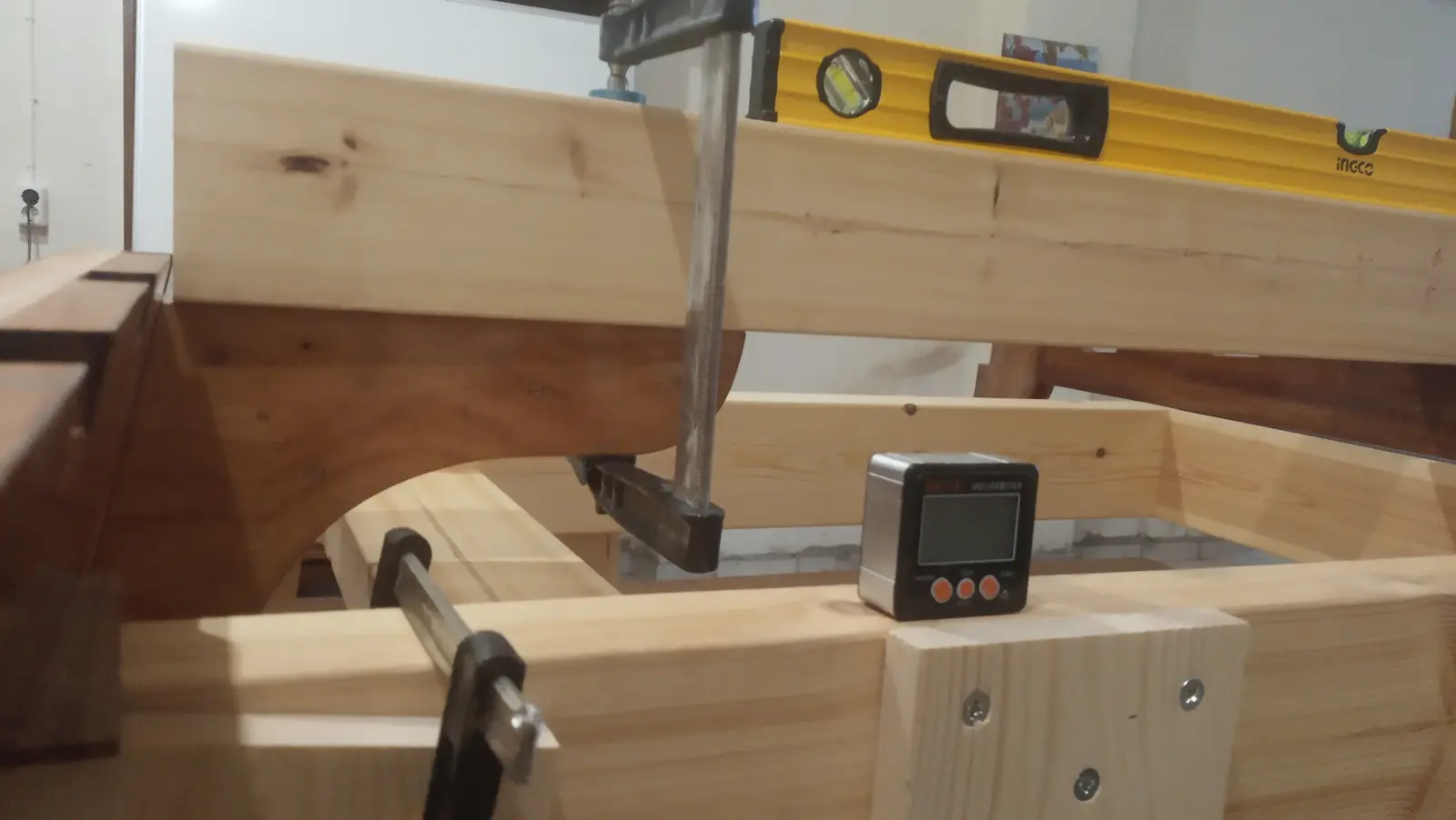
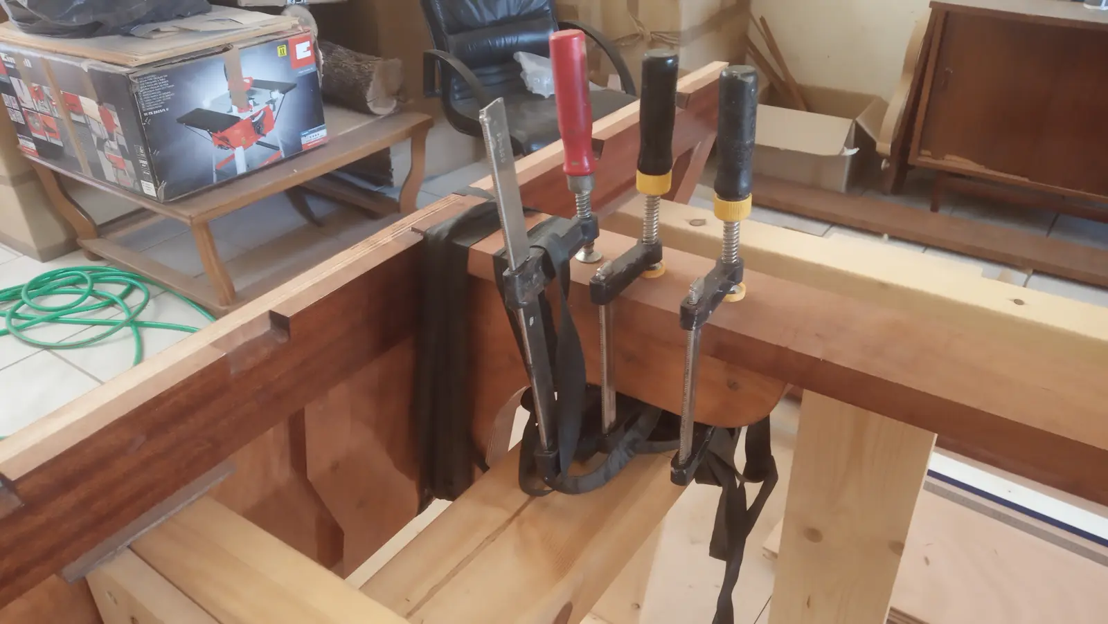
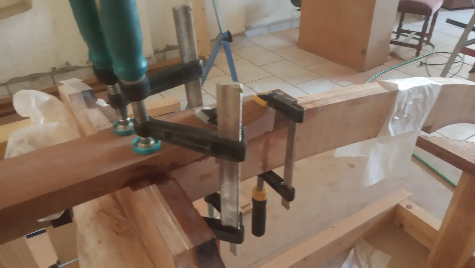
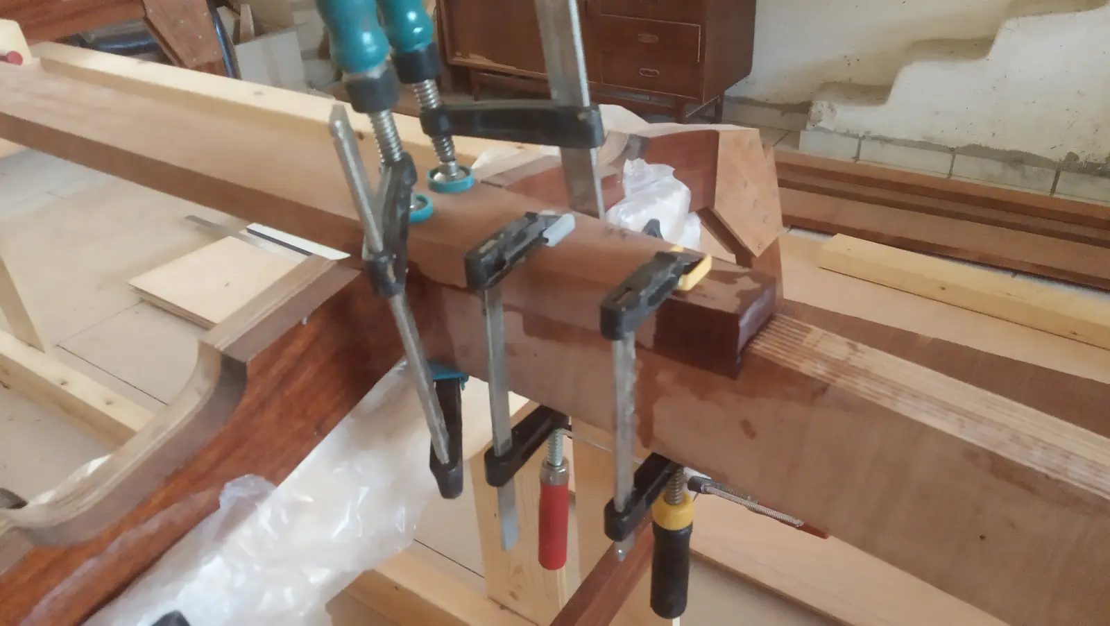
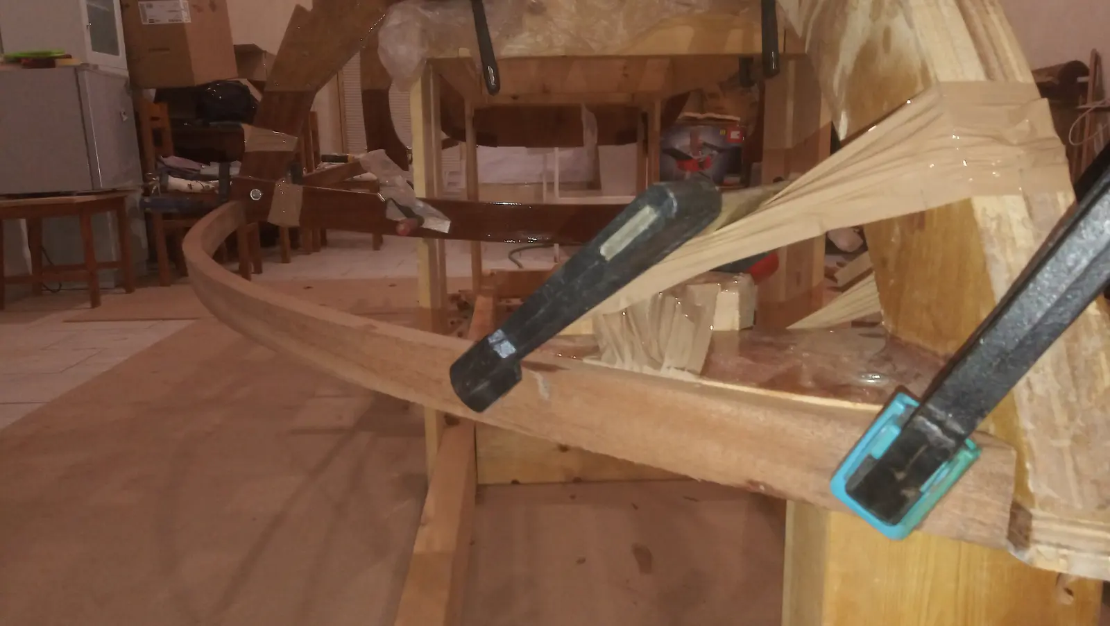
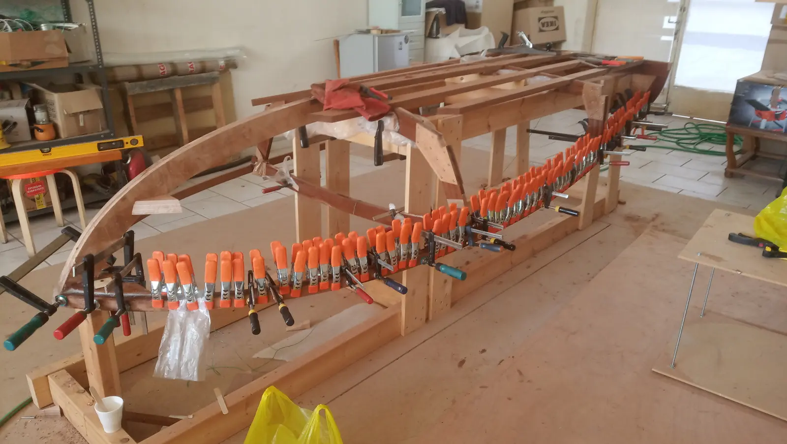
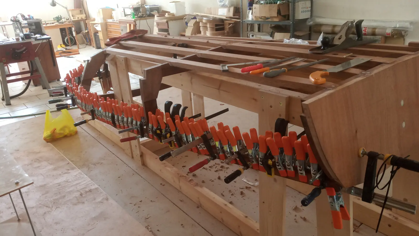
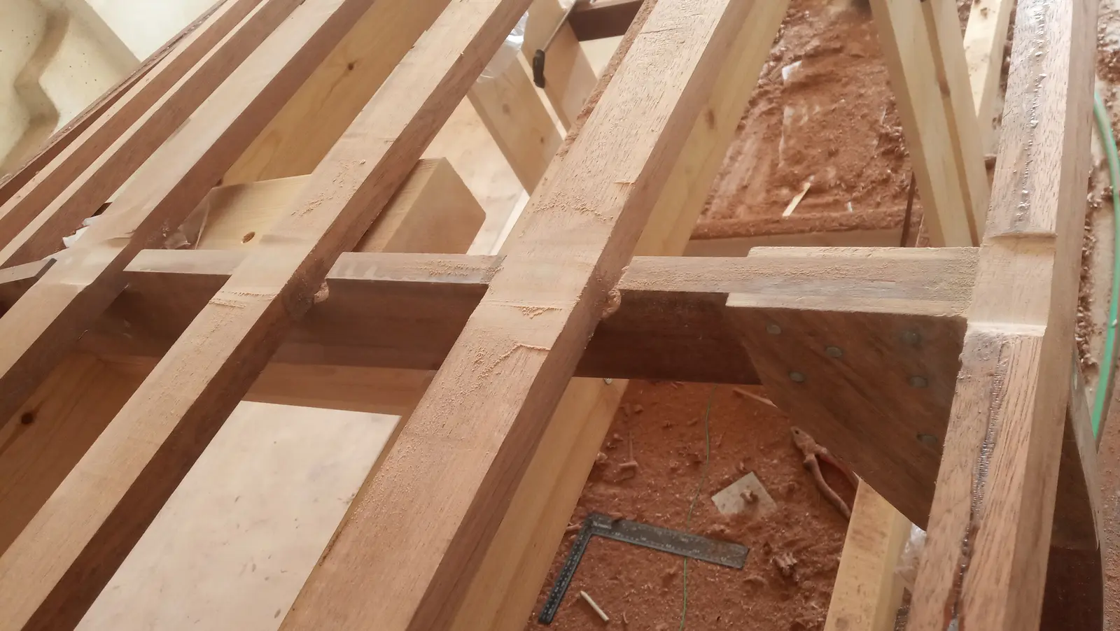
Some photographs of the glue-up with the clamps.
The next job was gluing the last timbers of the boat's framework, the chines. I had overestimated what my steamer could do and had intended to glue a single 2.5 cm thick piece on each side. After an hour the timber bent fairly easily, but it also had to twist along its length at the same time, a long way, and in opposite directions at different points. I could not do it.
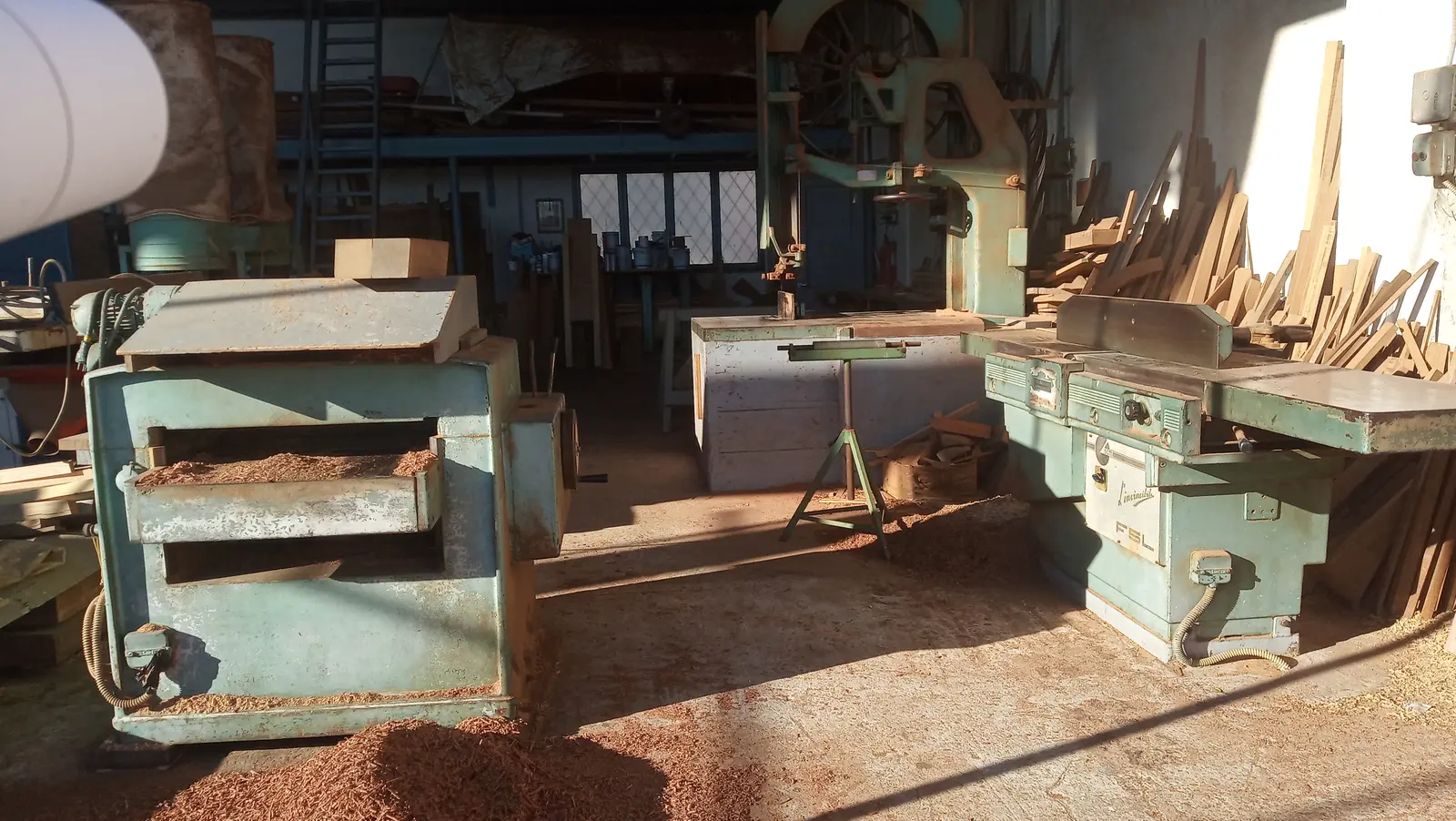
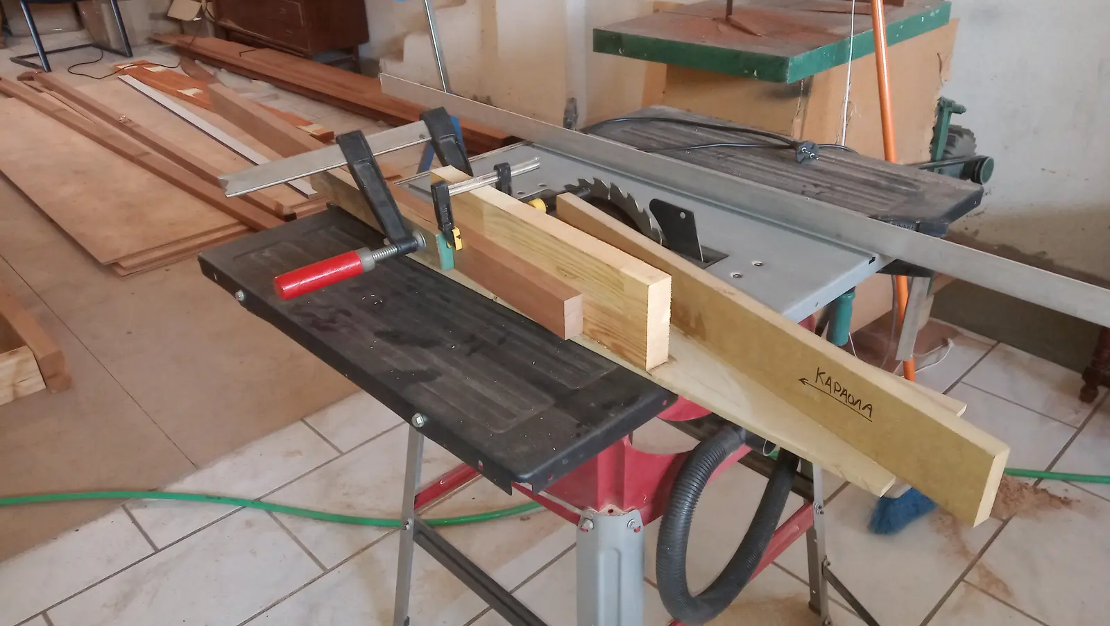
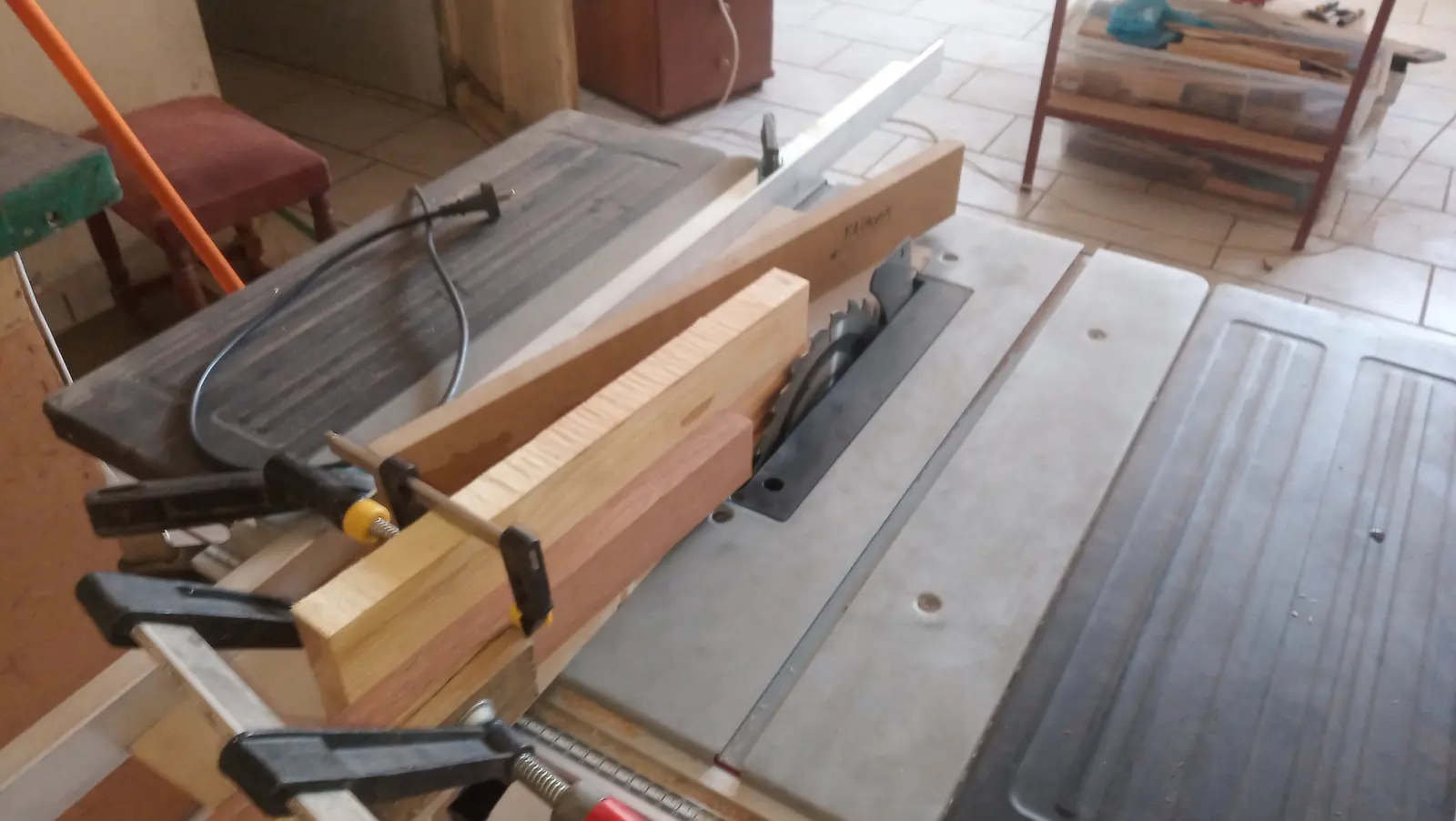
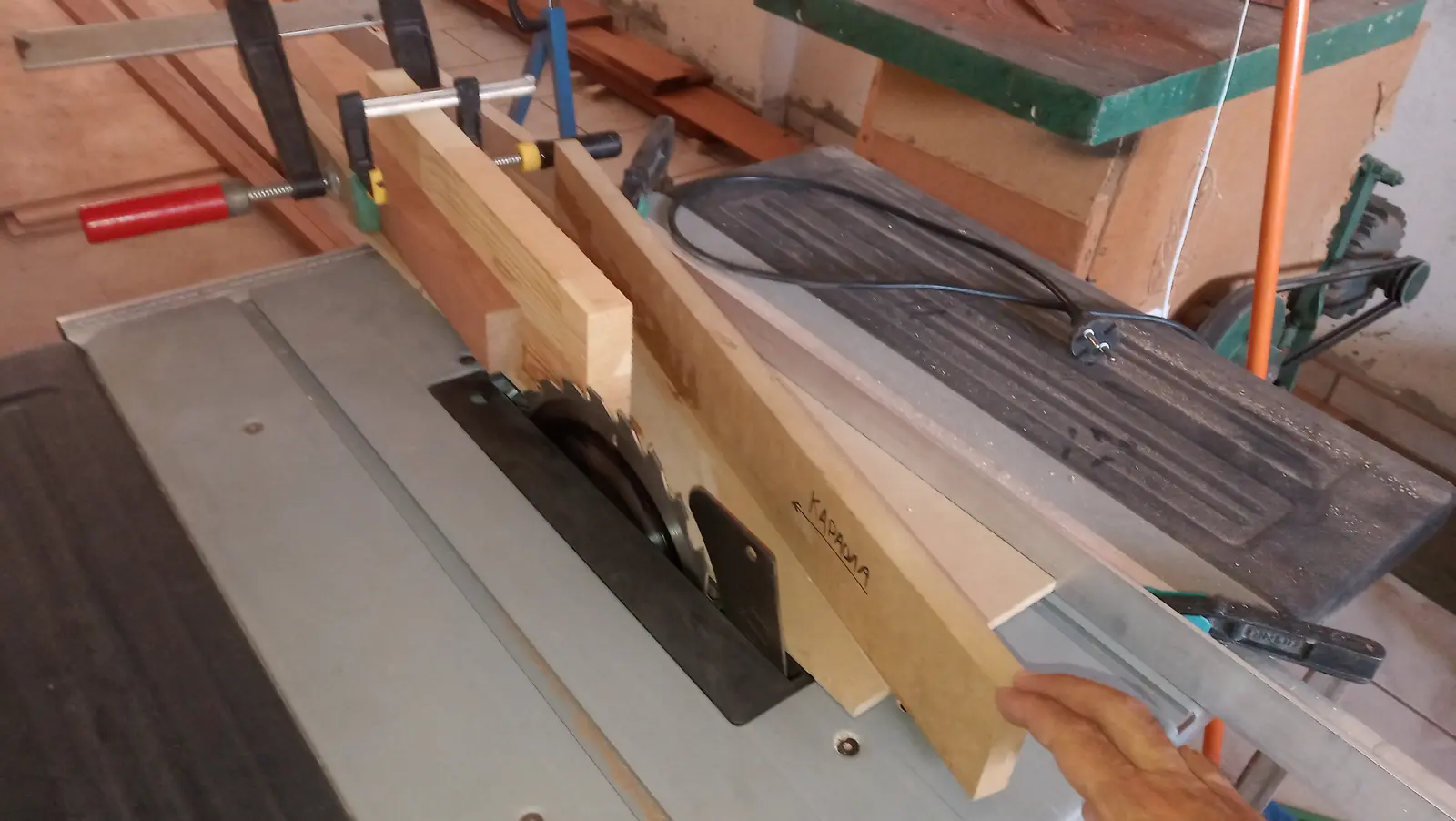
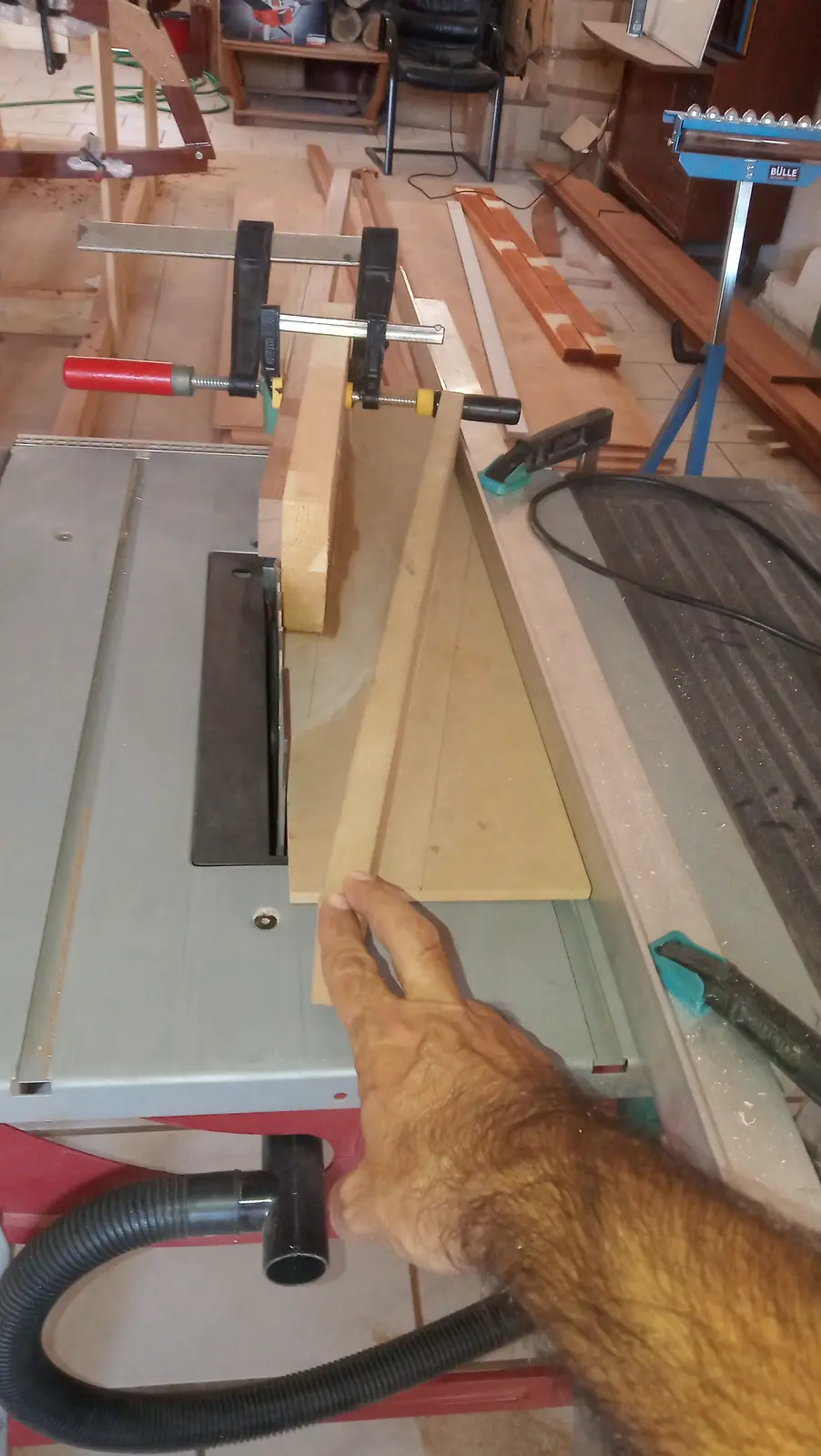
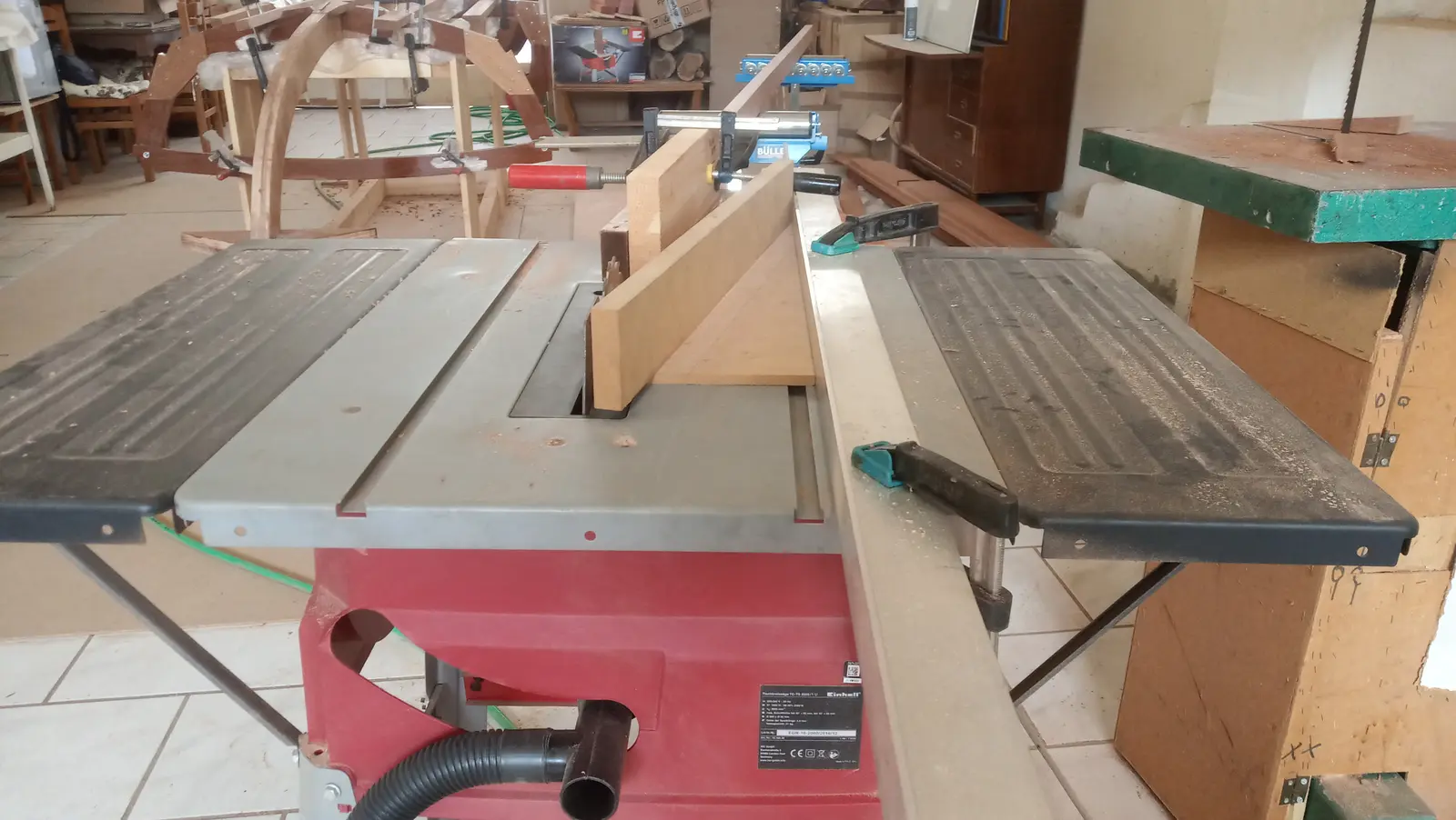
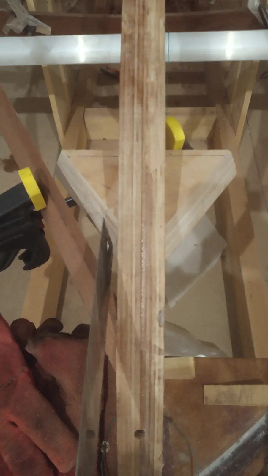
In the end I cut the pieces in half on the bandsaw. That left roughly two pieces of 1.1 cm of clean timber. If anywhere needs to be thicker, a third piece will be glued on.
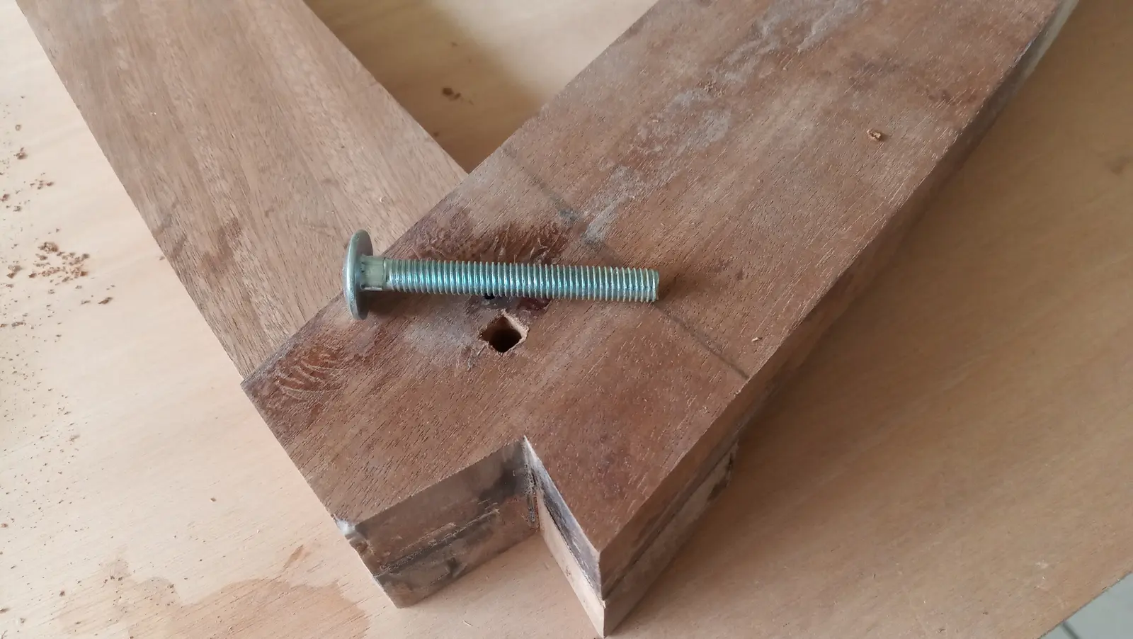
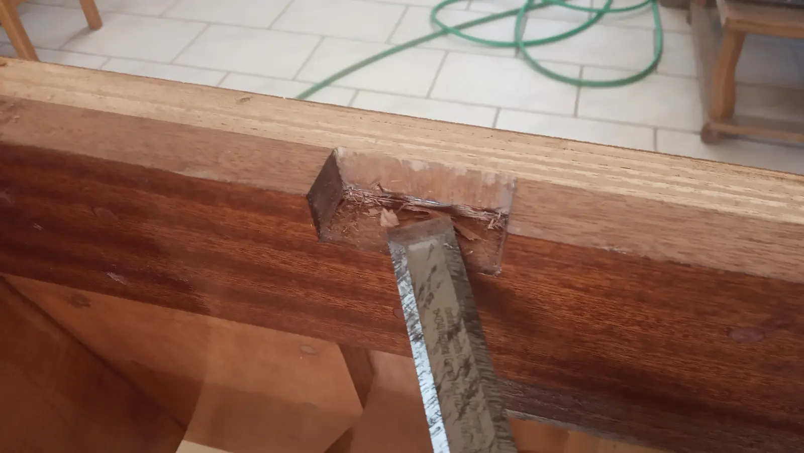
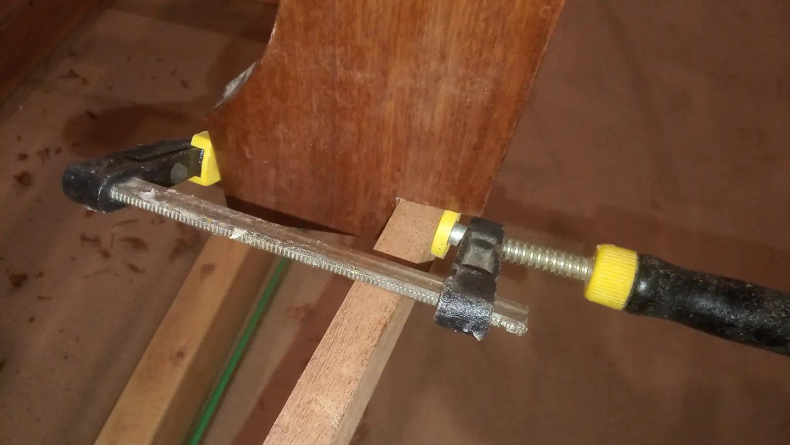
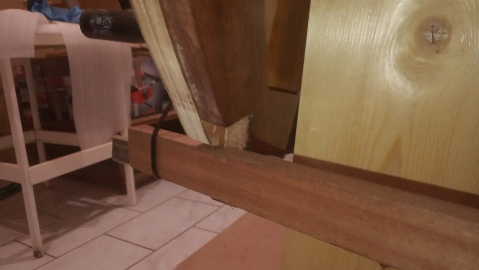
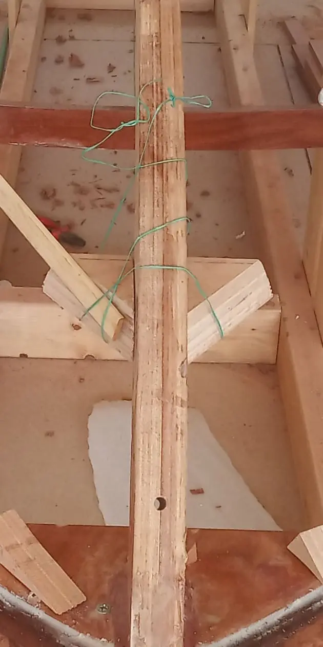
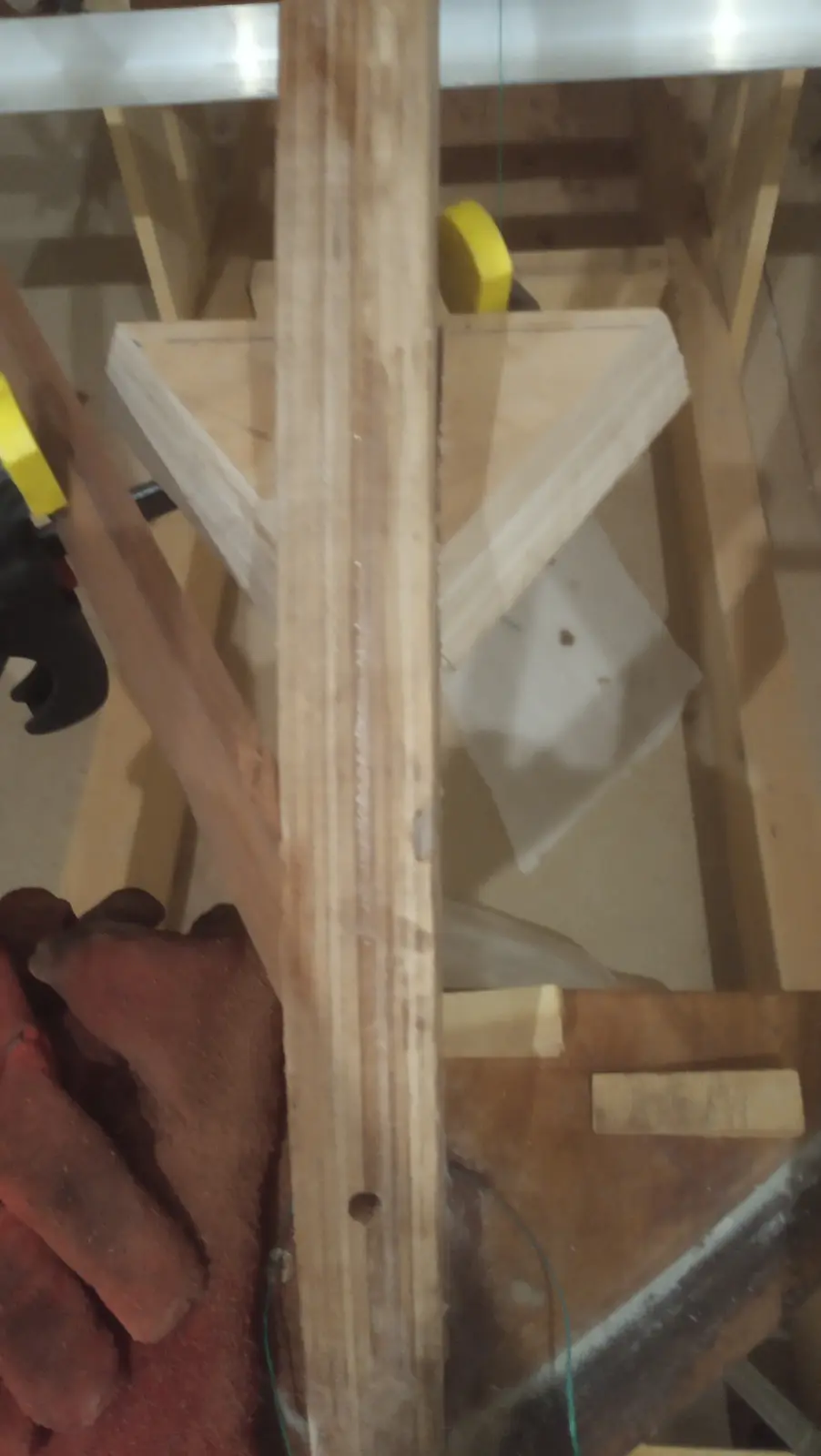
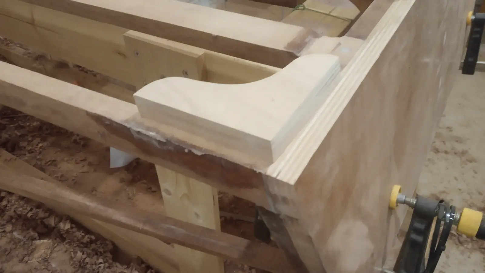
I found that the gluing surface, done the way the plans show it, would be very small indeed. It makes no sense to glue nothing but end grain onto the keel at an angle. So I decided to make a backing piece like the one the sheer timbers land on. I took a rough measurement of the angle the pieces arrive at and copied it onto the backing piece. Thirty-six degrees on each side. Also 12 degrees off vertical, which turned out to be wrong. It needed more, read on.
The points at the transom and at the first frame, which did not need much bending, were glued first. Then they were heated with the steamer and glued at the second frame. I chose to glue the forward point last, so I could see where the backing piece would need to go. One problem that can come up is these timbers sitting lower than the surface formed by the plywood that joins the sheer timber to the keel. If that happens it will spoil the shape of the boat forward (the V). The higher up it goes (with the boat upside down) the further the timber stands off the surface, but the harder it gets, since its natural tendency is to go downwards (it has to be bent with heat). The plans do not say where they should be fixed. They say it does not particularly matter.
After the final bend I found the right spot to glue the backing piece. The timber was cut at the right point ready for gluing, and the backing piece was glued on.
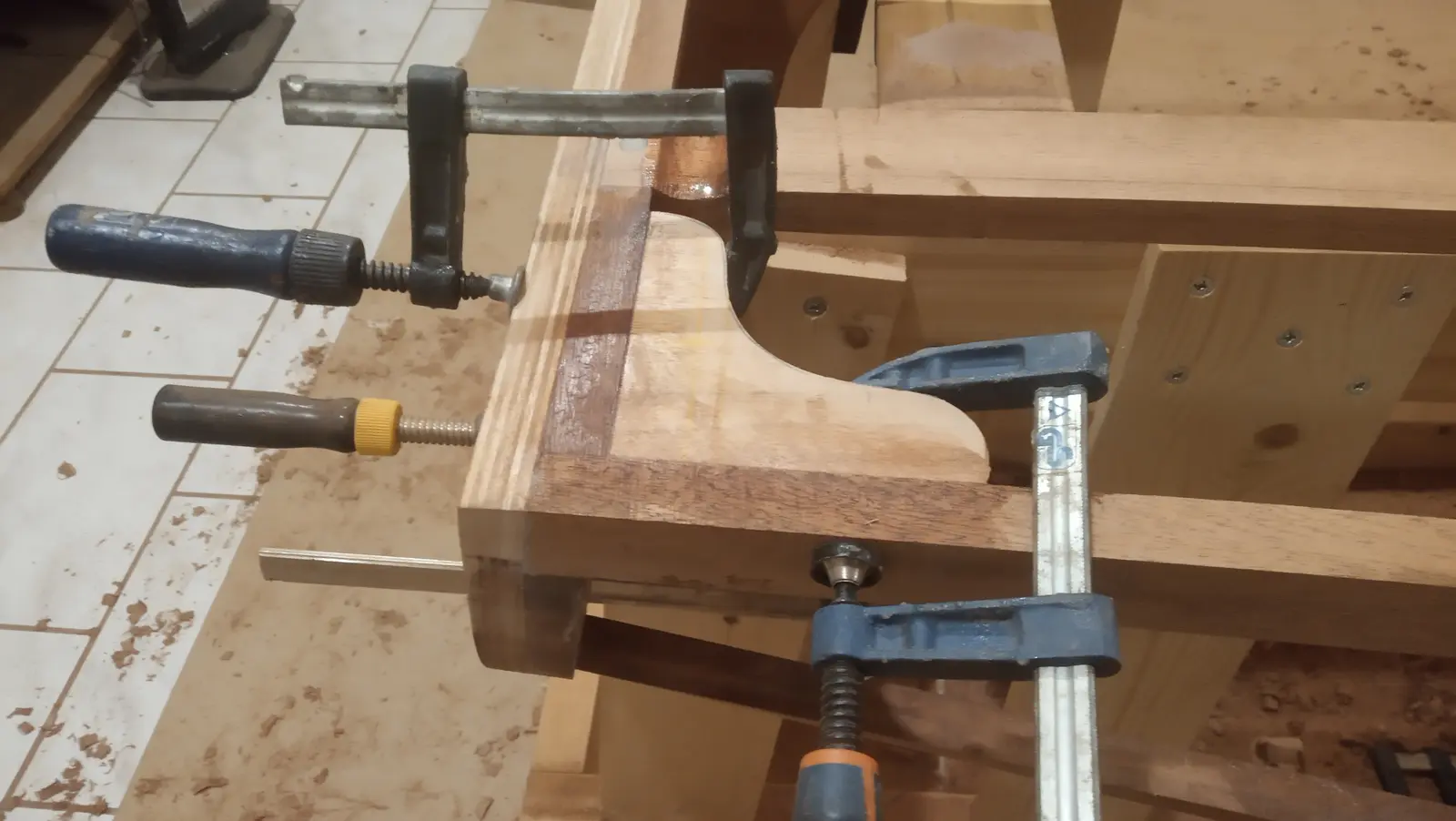
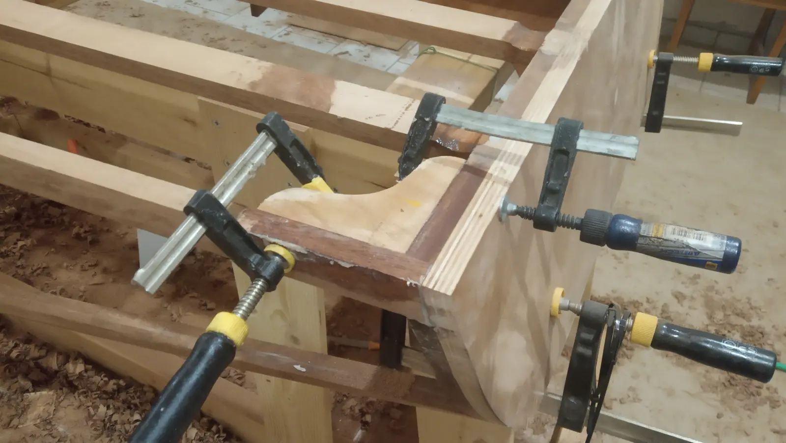
Then came the glue-up, with a lot of clamps.
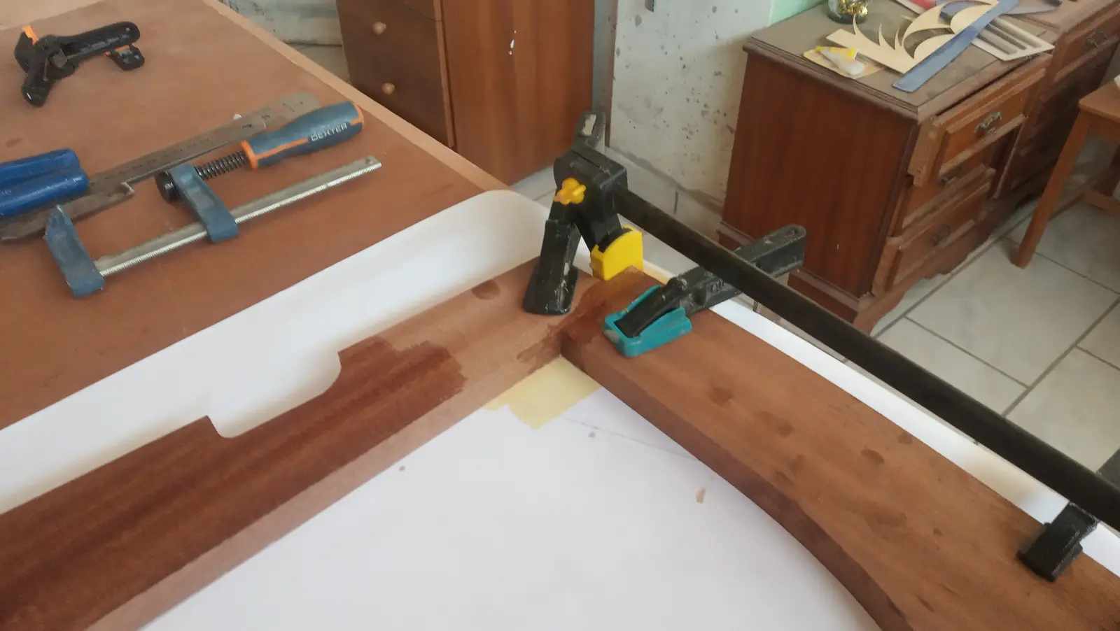
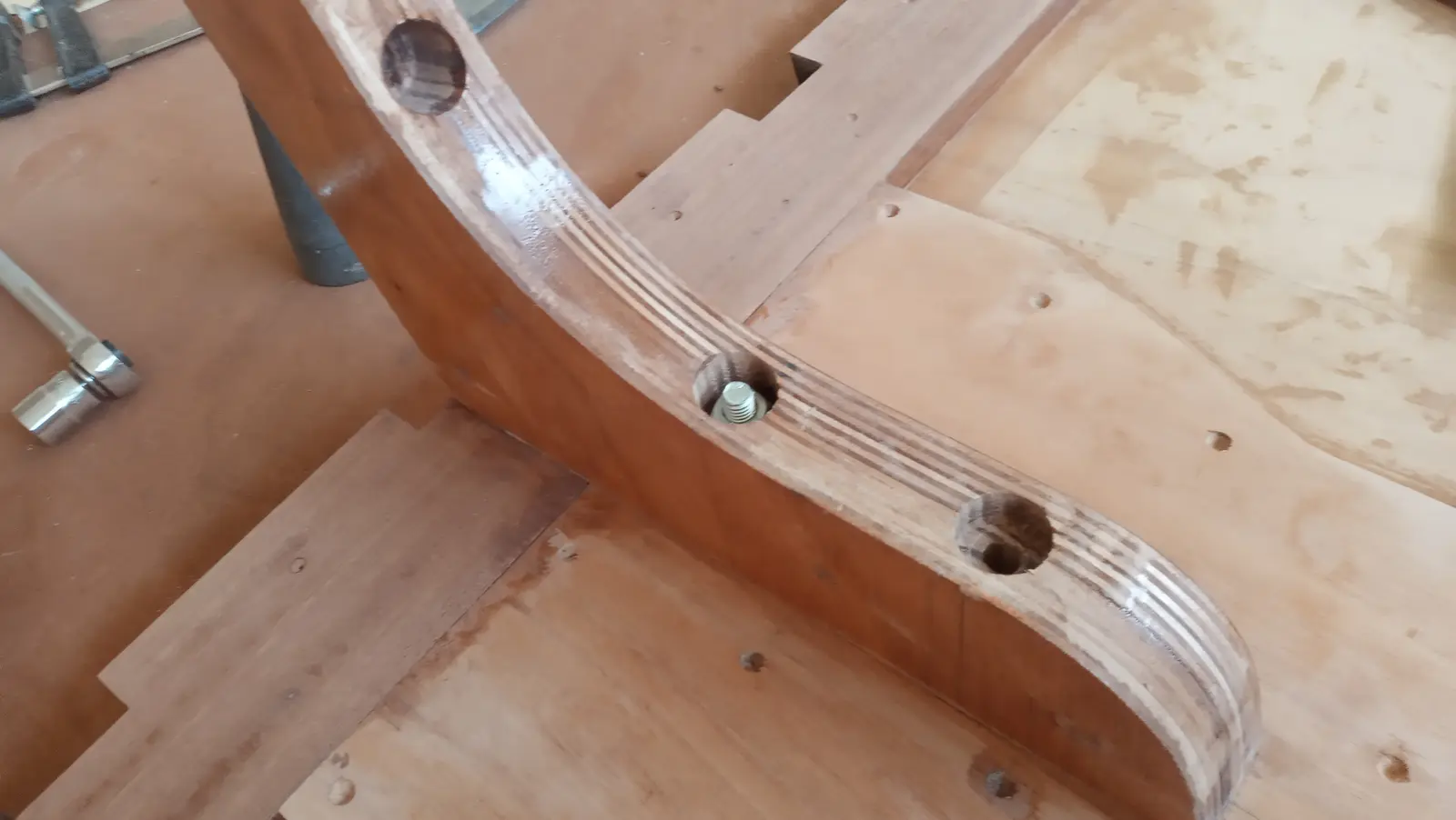
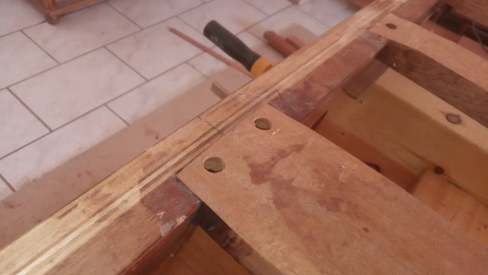
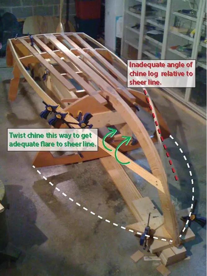
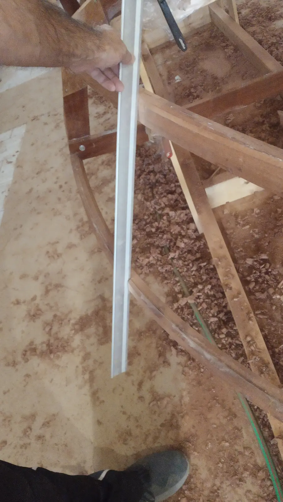
Once both pieces were glued I found their bevel was wrong. I found the photograph below from another build to make the problem clear. The bevel shown by the red line is the problem. The red line should come outside the white one, so that the timber can be cut back to a bevel the plywood can be glued to.
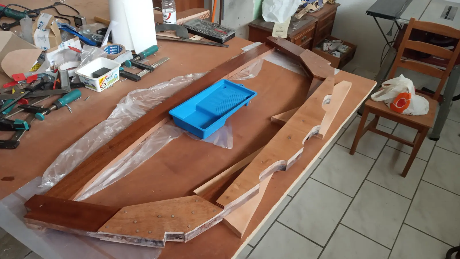
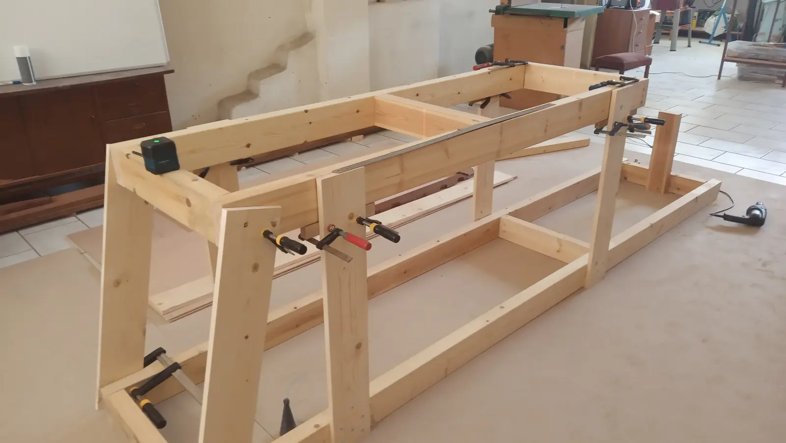
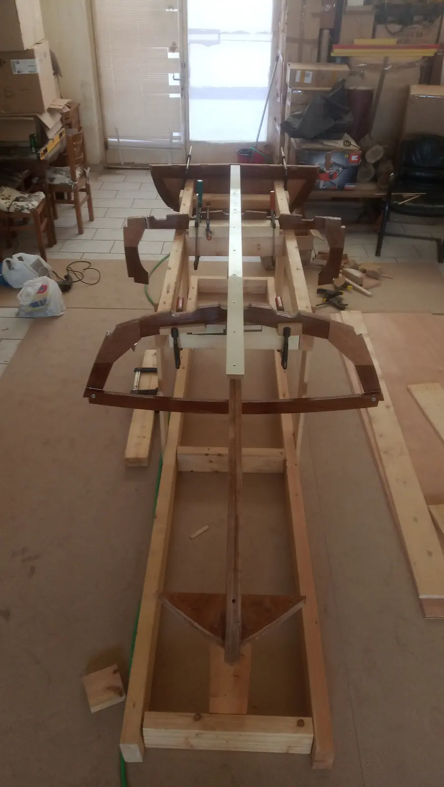
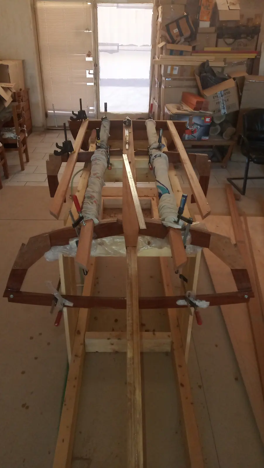
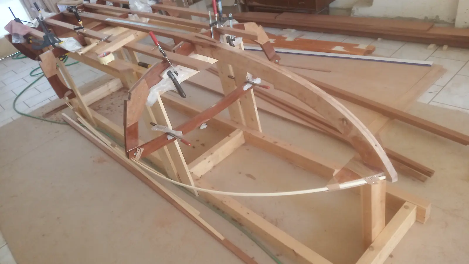
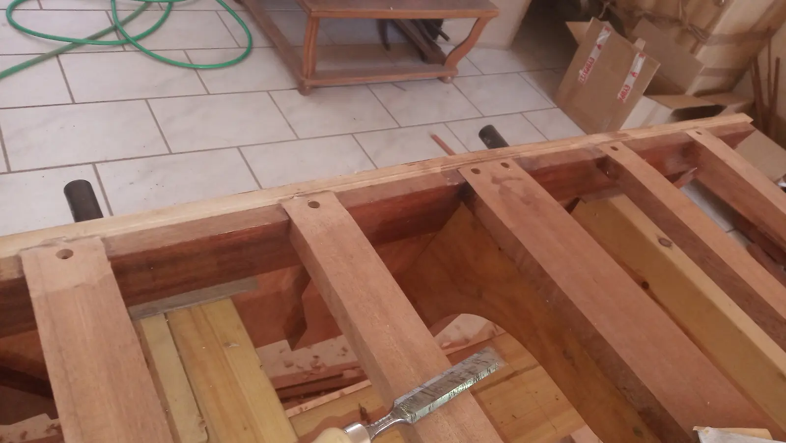
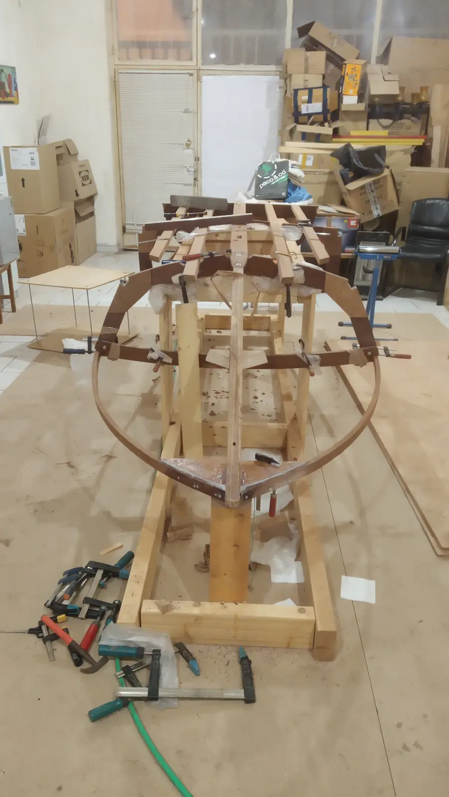
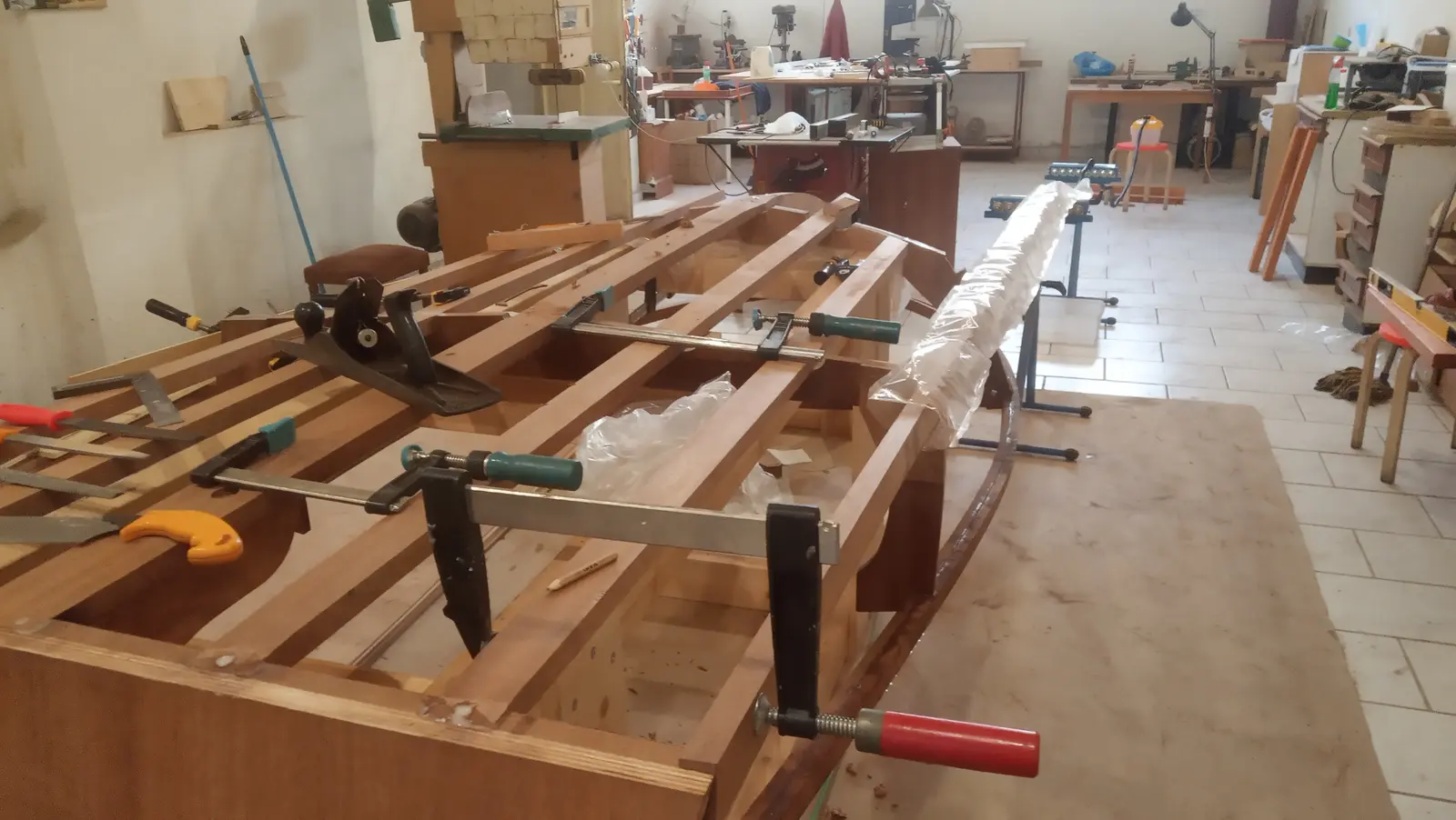
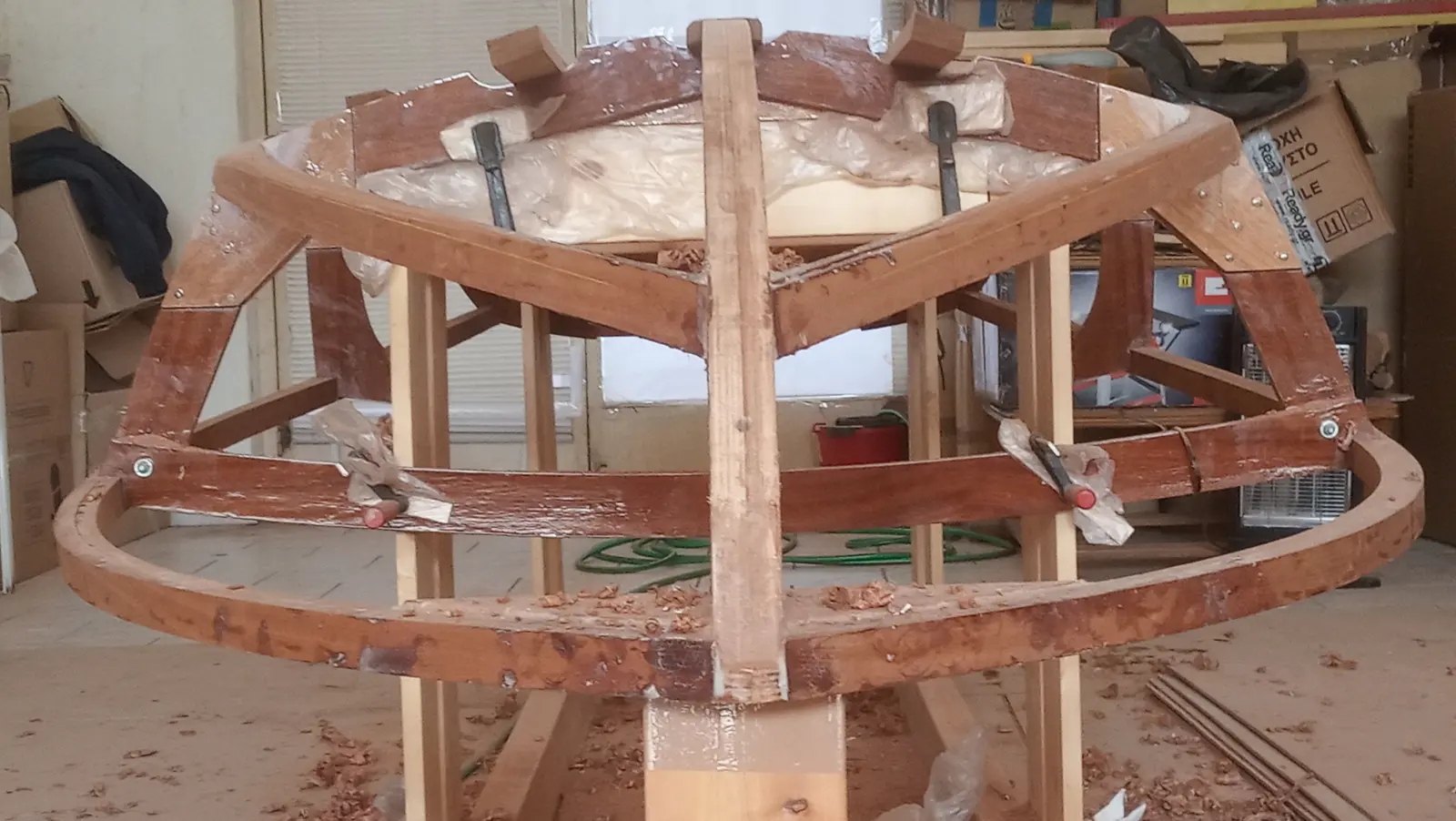
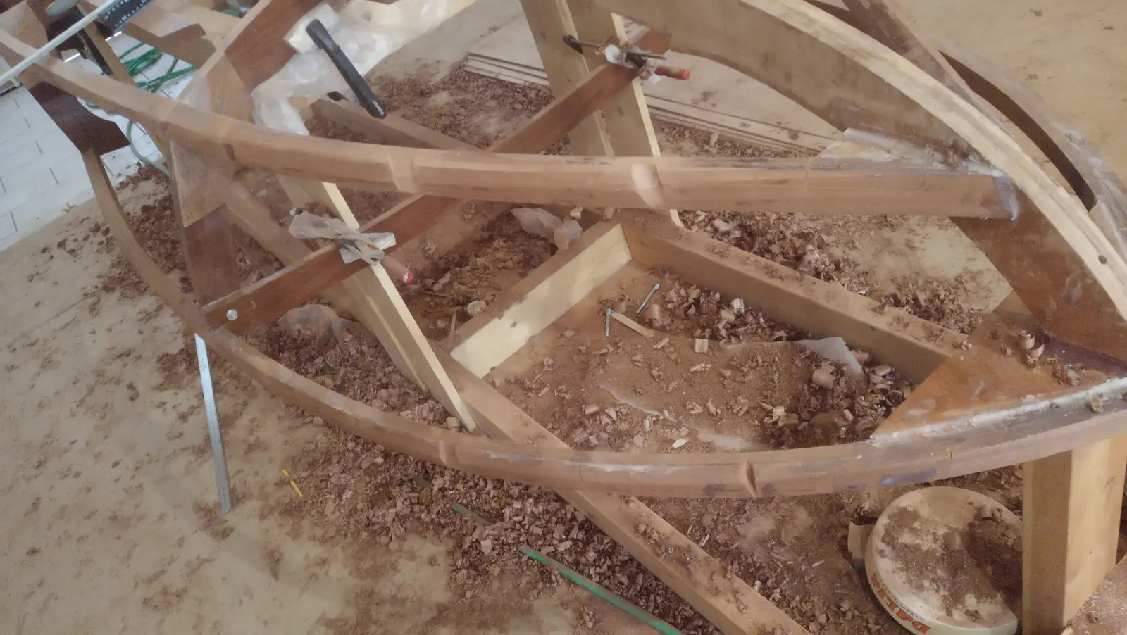
To get that bevel I would either have to unglue and reglue the timbers, which is very difficult with epoxy, or glue new pieces on top and cut a new bevel. This is a mistake which, as I found out, has been made on almost every build of this particular boat. The photograph below shows the framework in its final state.