The book is laid out for the paper chosen above, and the print dialog will follow it,
so pick the paper here rather than there. Turn background graphics on
so the cover photograph prints, and leave margins at their default. The page numbers
and the chapter running heads are drawn by the browser into the page margins, so they
exist only on paper: check the print preview rather than this screen for them, and turn
Headers and footers off there so Chrome's own furniture does not crowd
them out. Chrome and Edge print them, Safari and Firefox print the same book without
them.
new build
Kembali
The Guider
Jeffrey Marso · 2023 to 2026
A build log
Kembali
The Guider
kept by Jeffrey Marso, Vancouver, WA., USA
2023 to 2026
The boat
The Guider
Designer
John C. Harris
Plans from
Chesapeake Light Craft
Length overall
18′ 7″ (5.66 m)
Beam
6′ 0″ (1.83 m)
Construction
lapstrake plywood
Started
17 October 2023
Launched
2 June 2026
Built by
Jeffrey Marso
Built at
Vancouver, WA., USA
4th boat. Biggest and most complex boat I have built.
What it took
By the numbers
51
Days written up
252
Photographs
5,372
Words written
$14,894
Spent in all
Went into the boat
$11,979.81
Shipping
$1,785.00
Tax
$1,128.78
Total
$14,893.59
The work
Contents
01Shop & Tooling
Oct 2023
02Hull Panels
Oct 2023
03Strongback & Molds
Oct 2023
04Stitch & Assembly
Nov 2023
05Hull Exterior
May 2024
06Glassing & Epoxy
Aug 2024
07Interior & Cockpit
Aug 2024
08Paint & Finish
Sep 2024
09Rig & Spars
Jan 2025
10Deck & Coamings
Mar 2025
11Systems
May 2025
12Hardware & Fit-Out
Jul 2025
16 Oct 2023
Received the kit, view of the work space
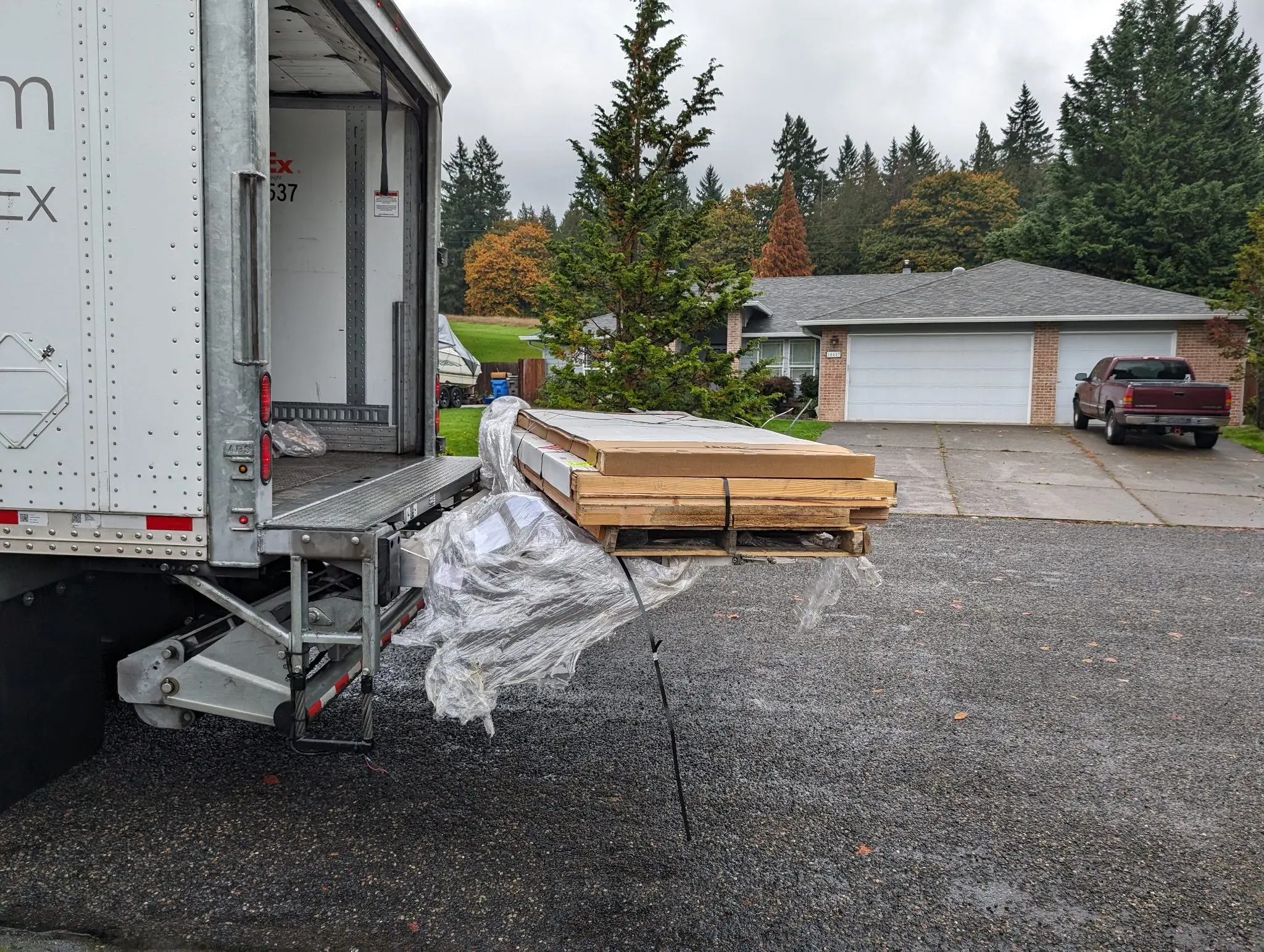
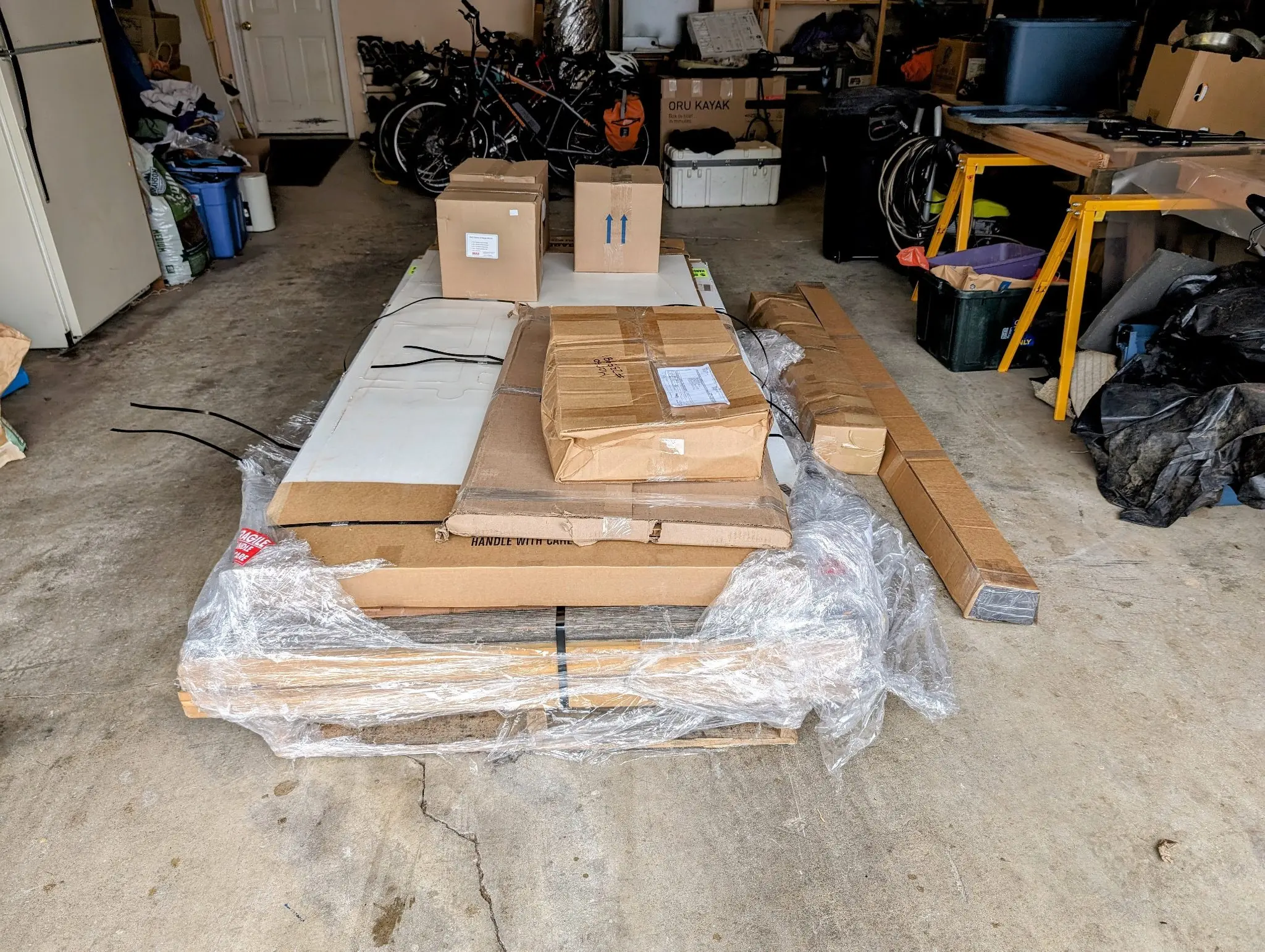
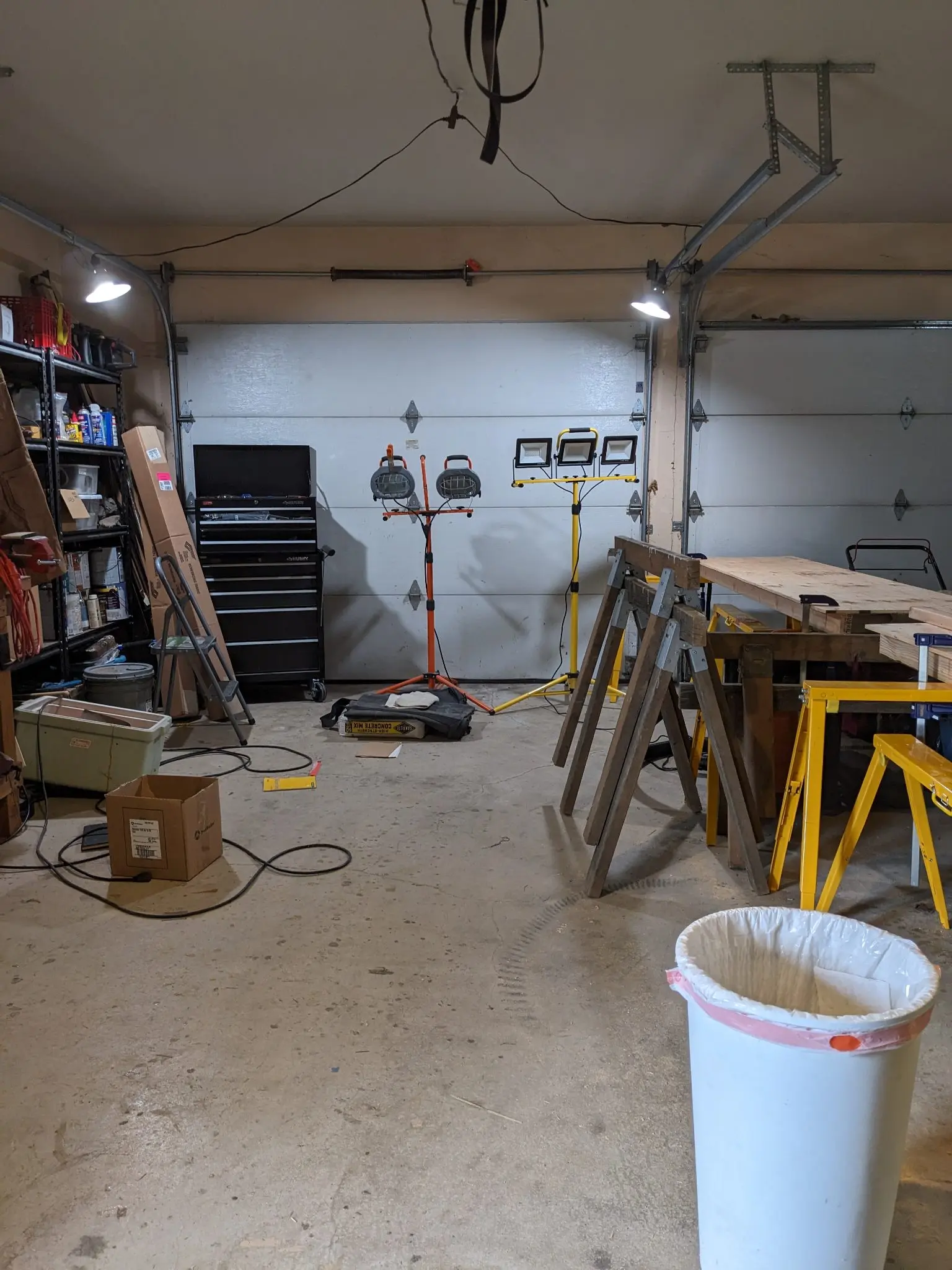
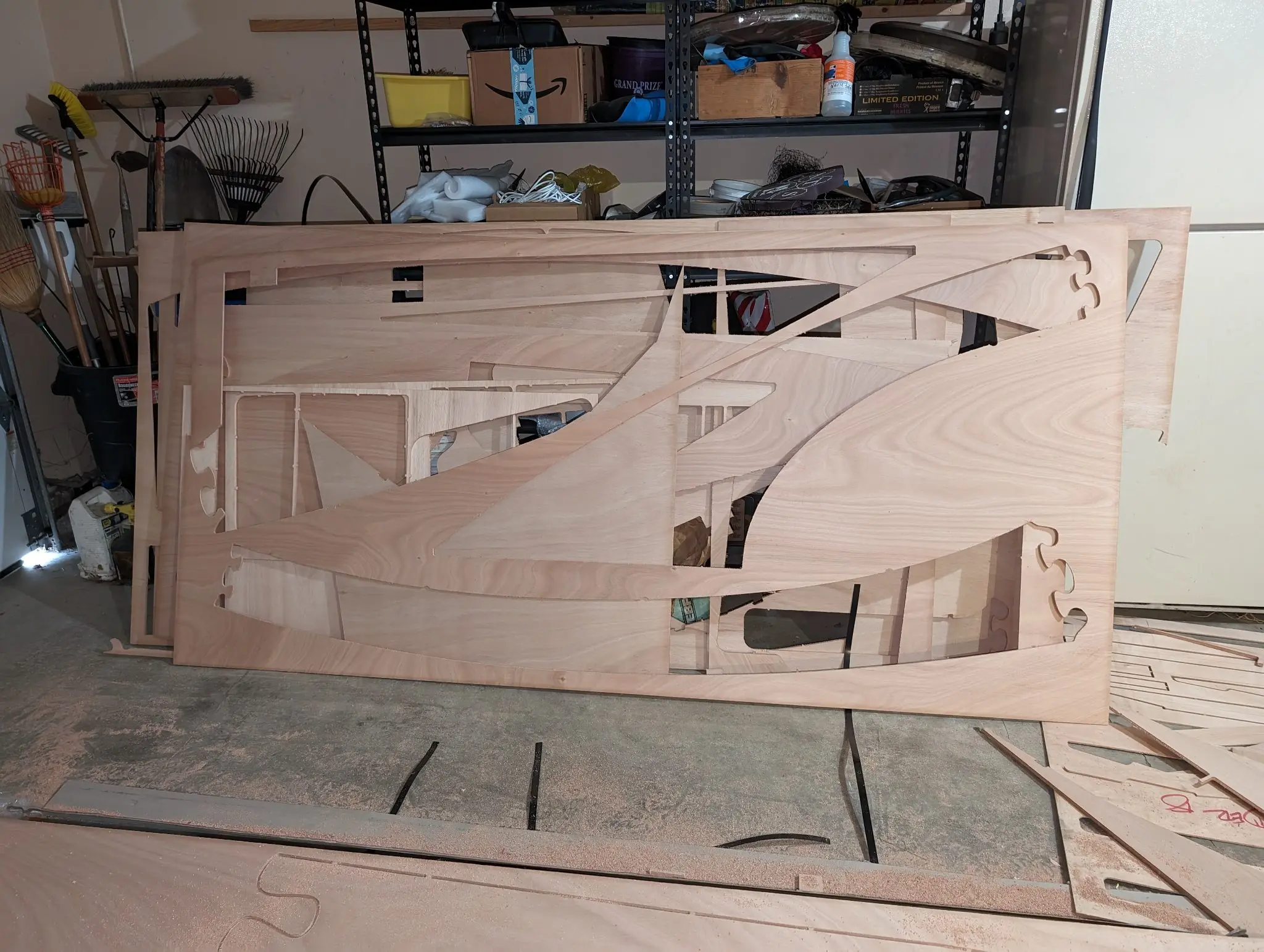
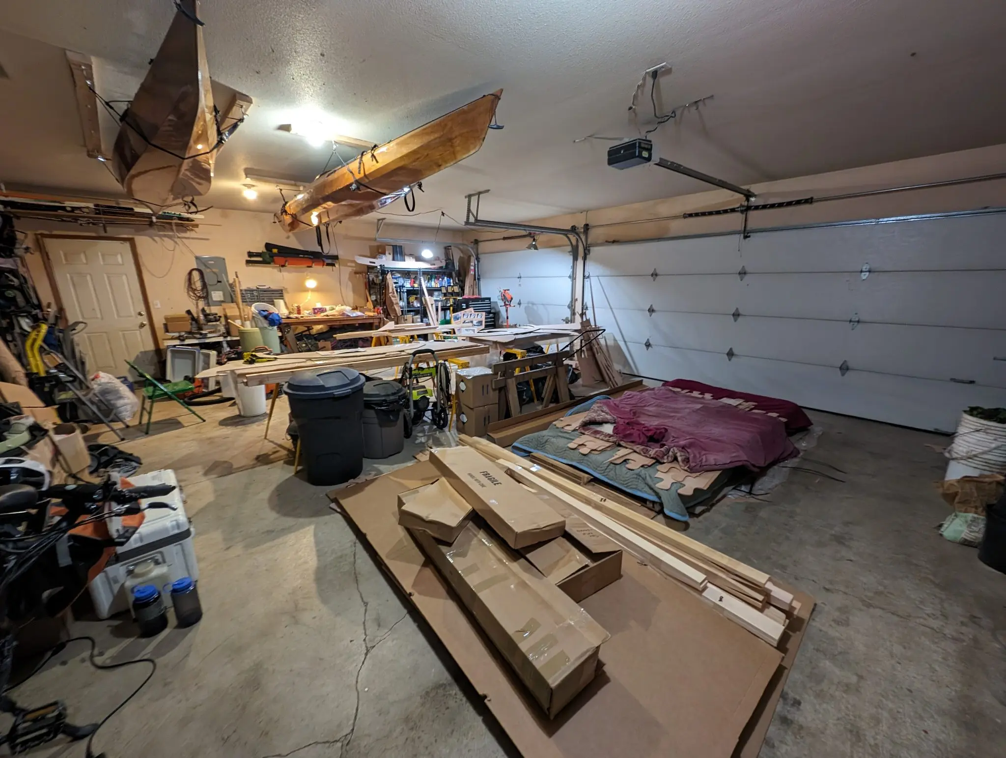
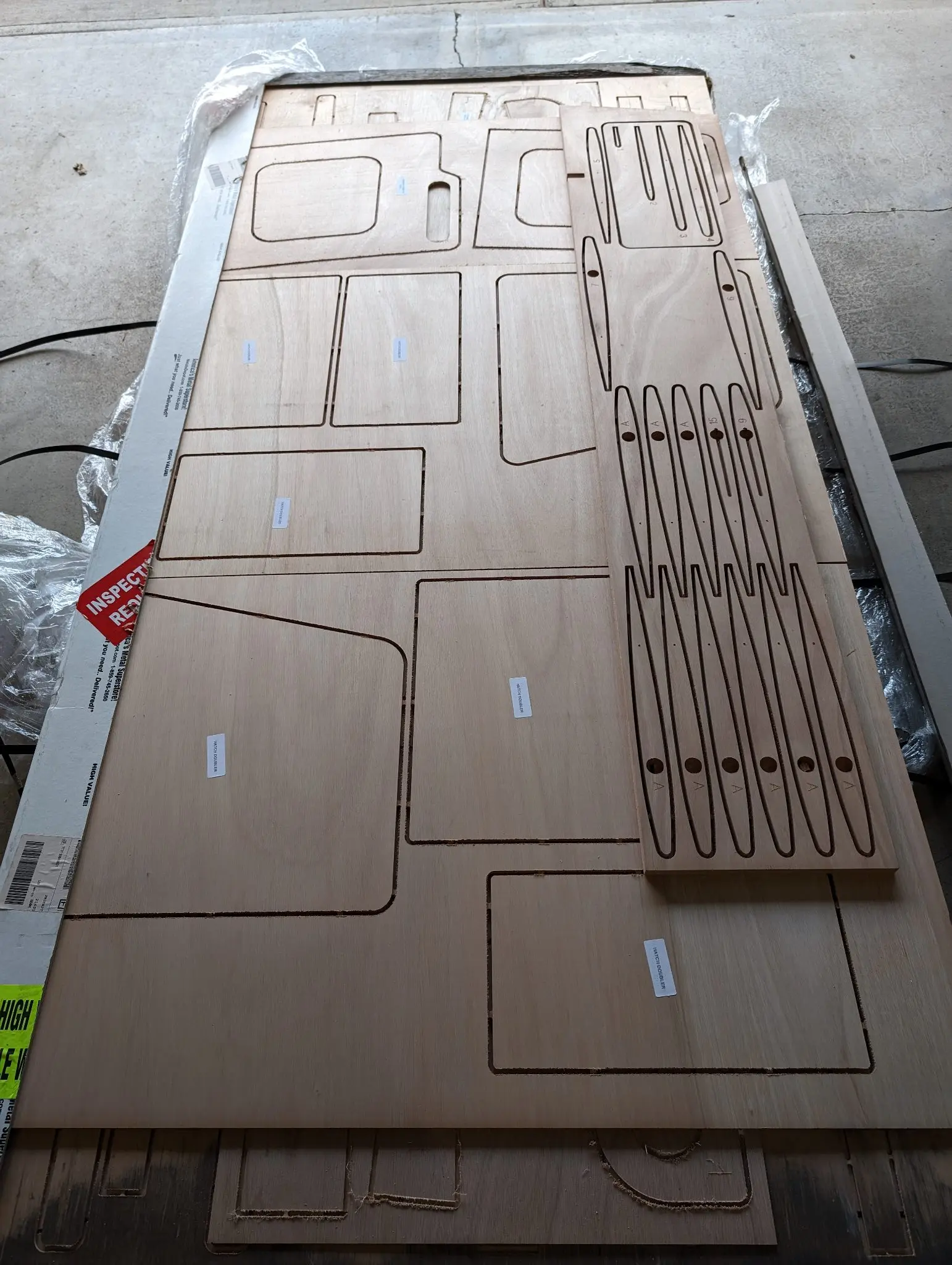
Received the kit from CLC. It was shipped via FedEx as a 1200 lb pallet and several assorted extras. One of the photos shows the build space, which includes two 8-foot sawhorse tables and occupies about 1/2 of a suburban 3-car garage.
Photo 1 Photo 2 Photo 3
Chapter 01
Shop & Tooling
Clearing space, building benches and jigs, buying or borrowing the tools the build needs.
1 dayfrom October 2023
17 Oct 2023Shop & Tooling
Unpack, check inventory, organize
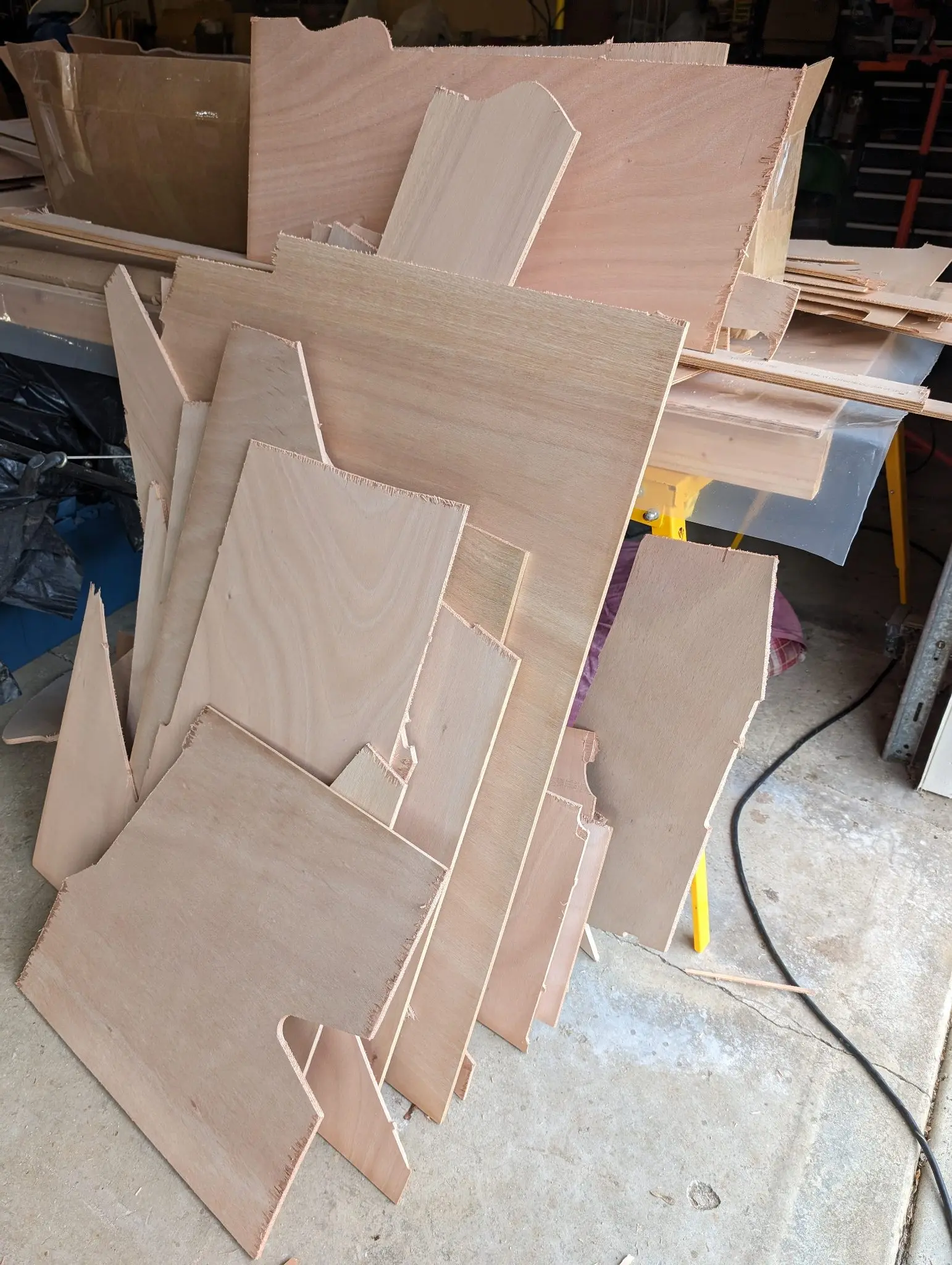
I pulled apart the pallet. The major components are all cut from about 9 full-sized sheets of Okoume marine plywood of various thicknesses. The parts have retaining tabs to hold them in the plywood. Once everything is freed from the sheets, there are some usable bits left behind. I have cut the biggest bits out of this waste and saved them. Then I organized all the parts and laid them out in some kind of order for assembly
Photo 1 Photo 2 Photo 3 Photo 4
Chapter 02
Hull Panels
Scarfing plywood, cutting panels, milling strips or planking stock.
1 dayfrom October 2023
28 Oct 2023Hull Panels
Gluing the hull planks
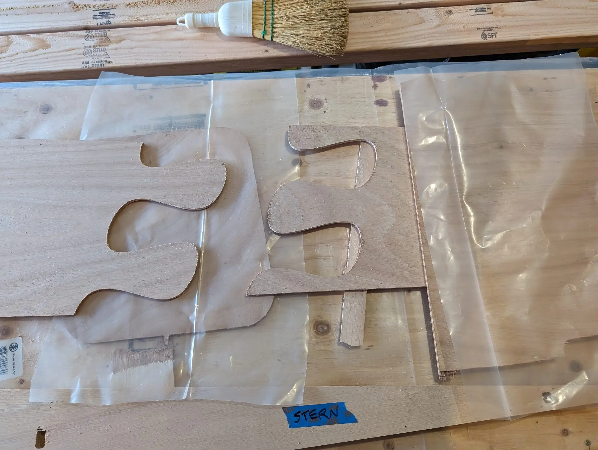
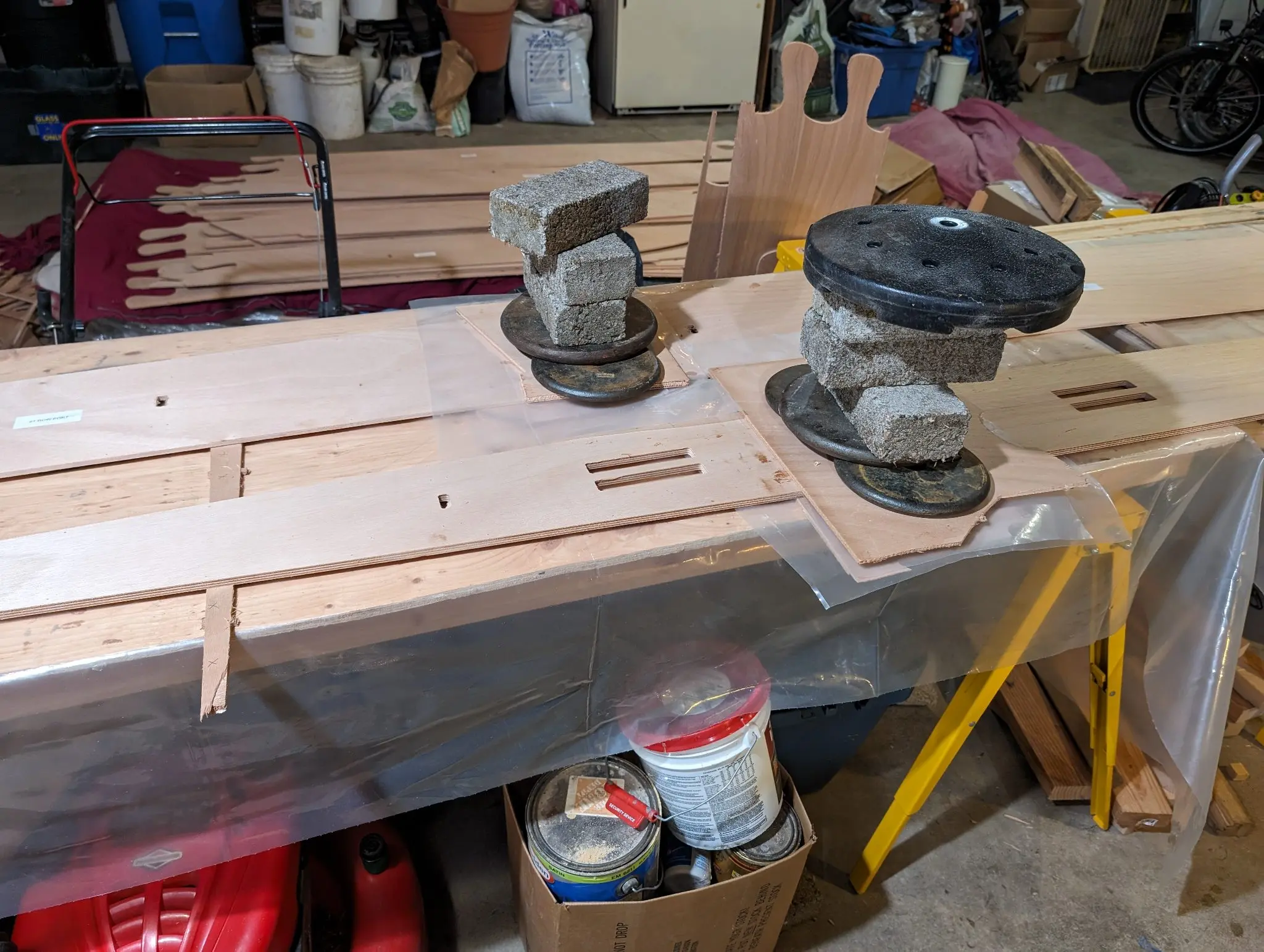
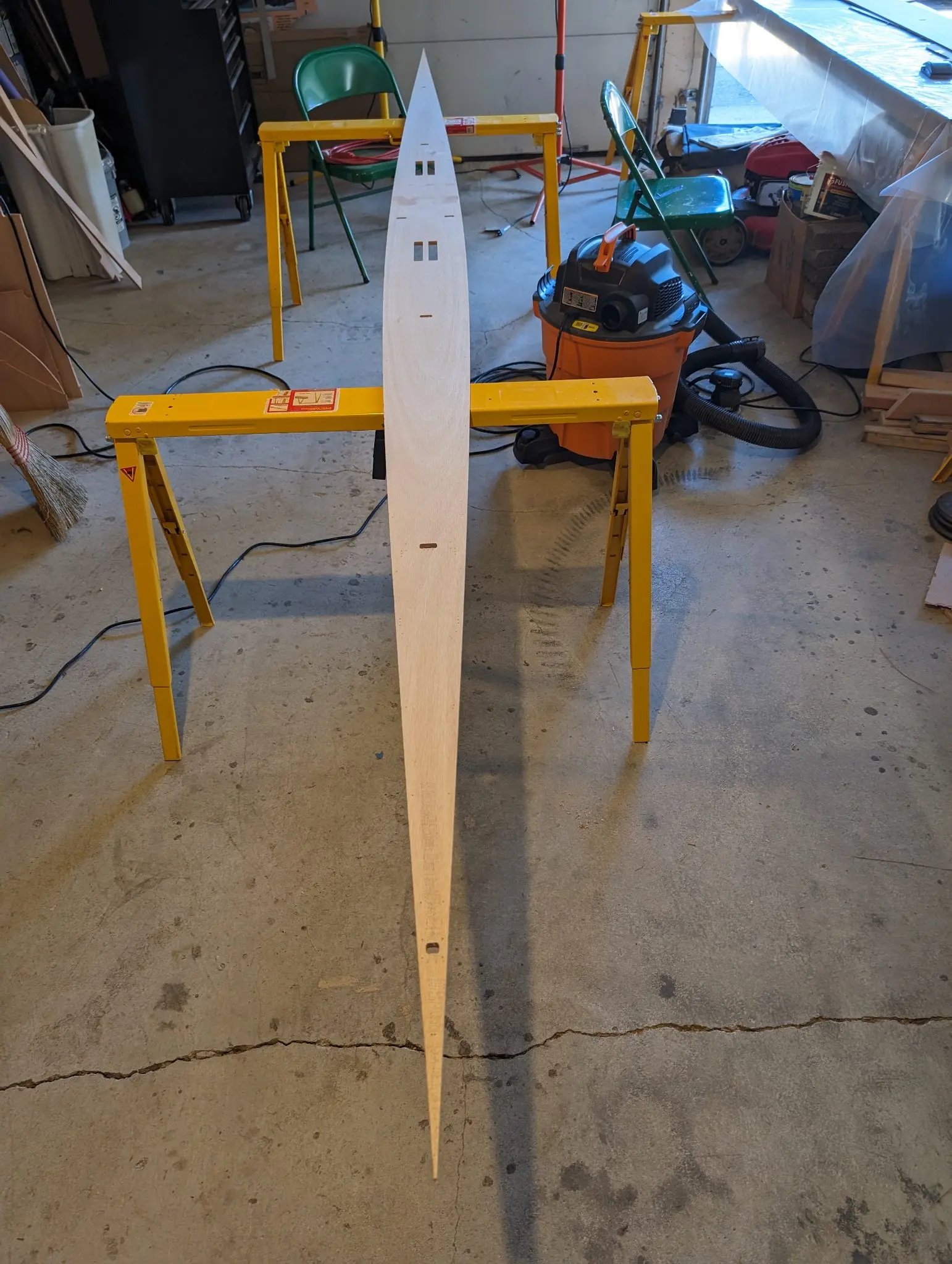
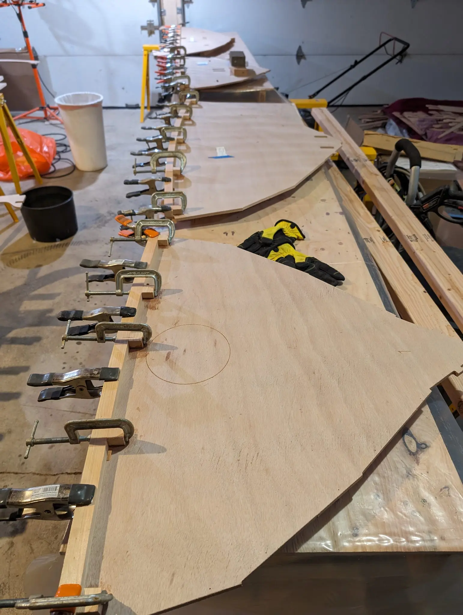
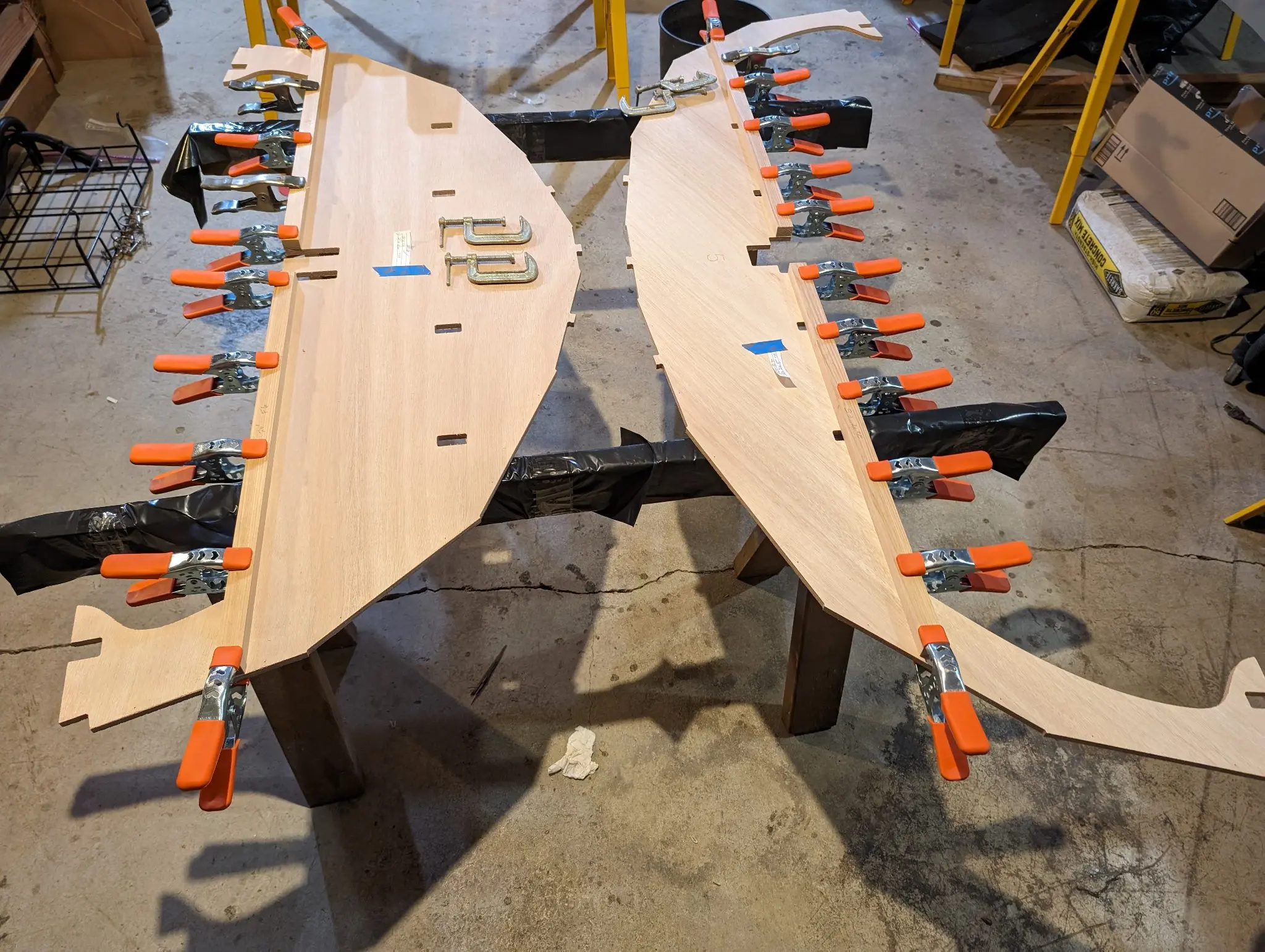
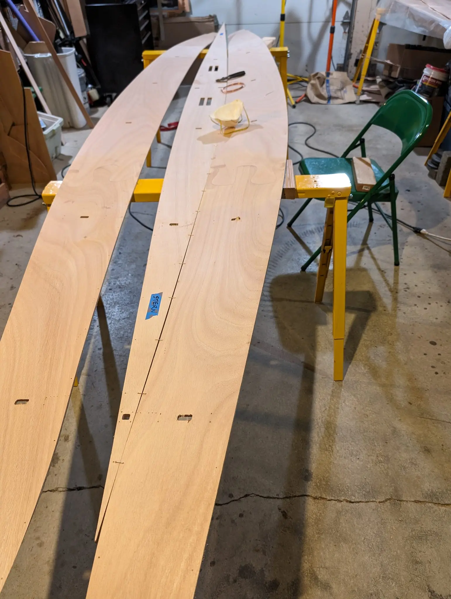
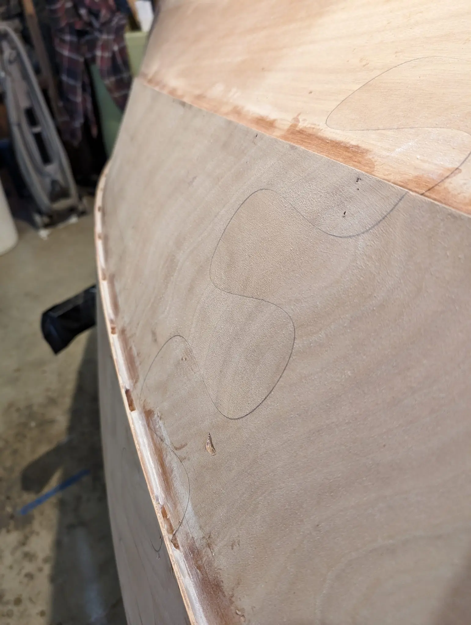
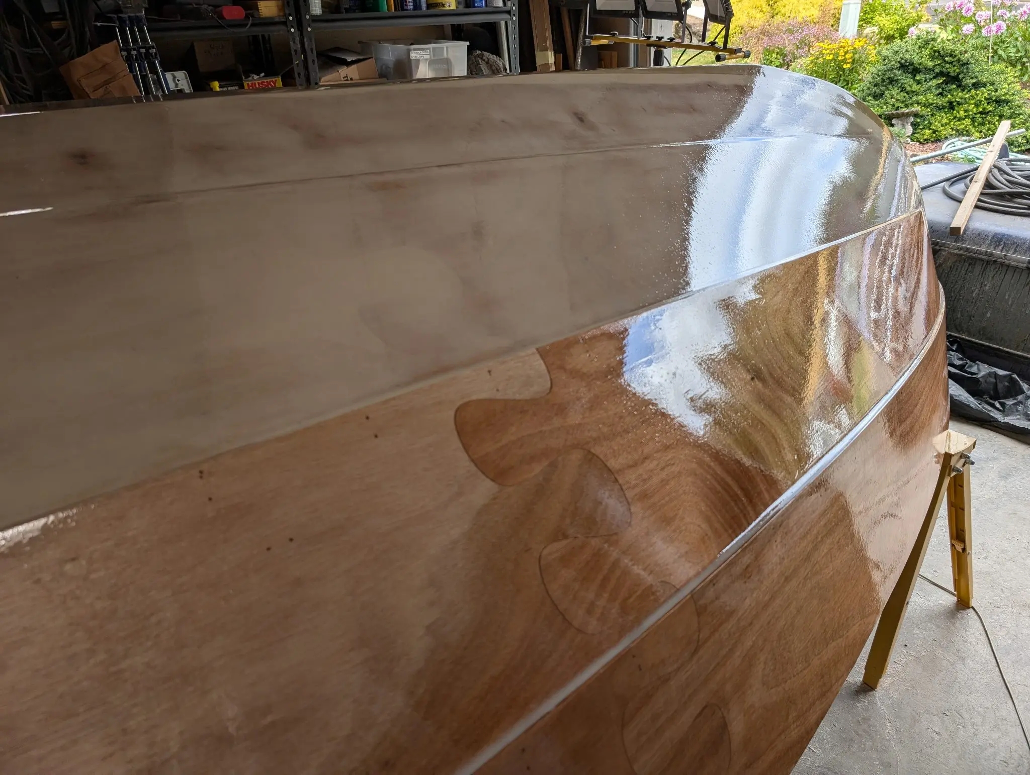
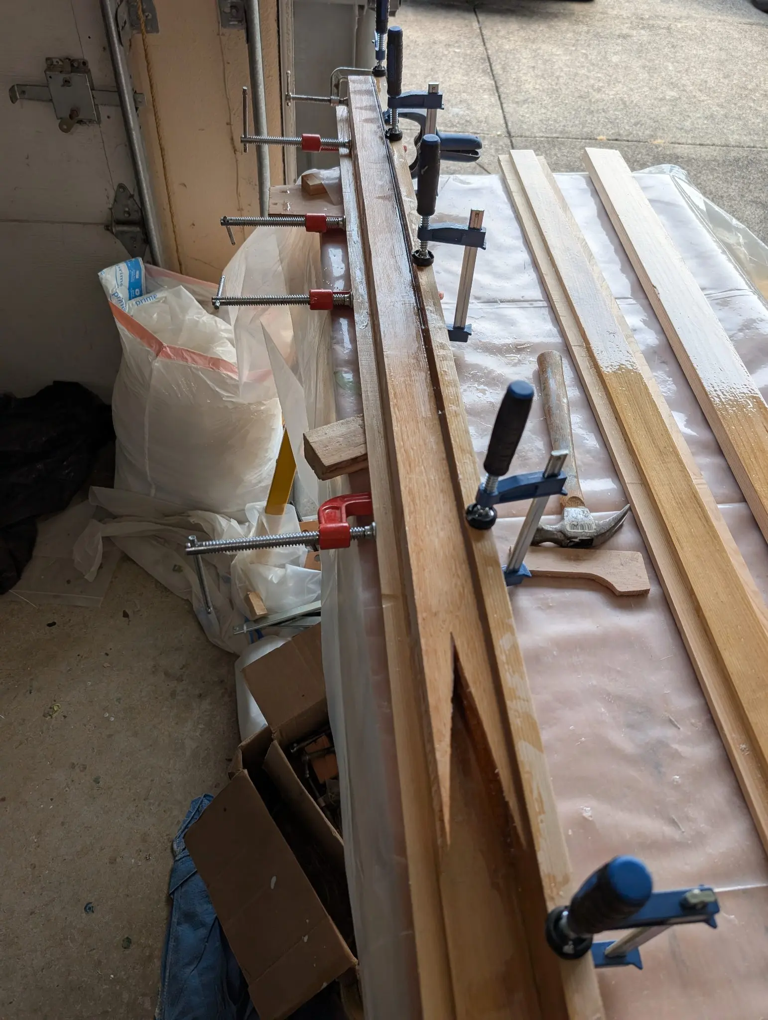
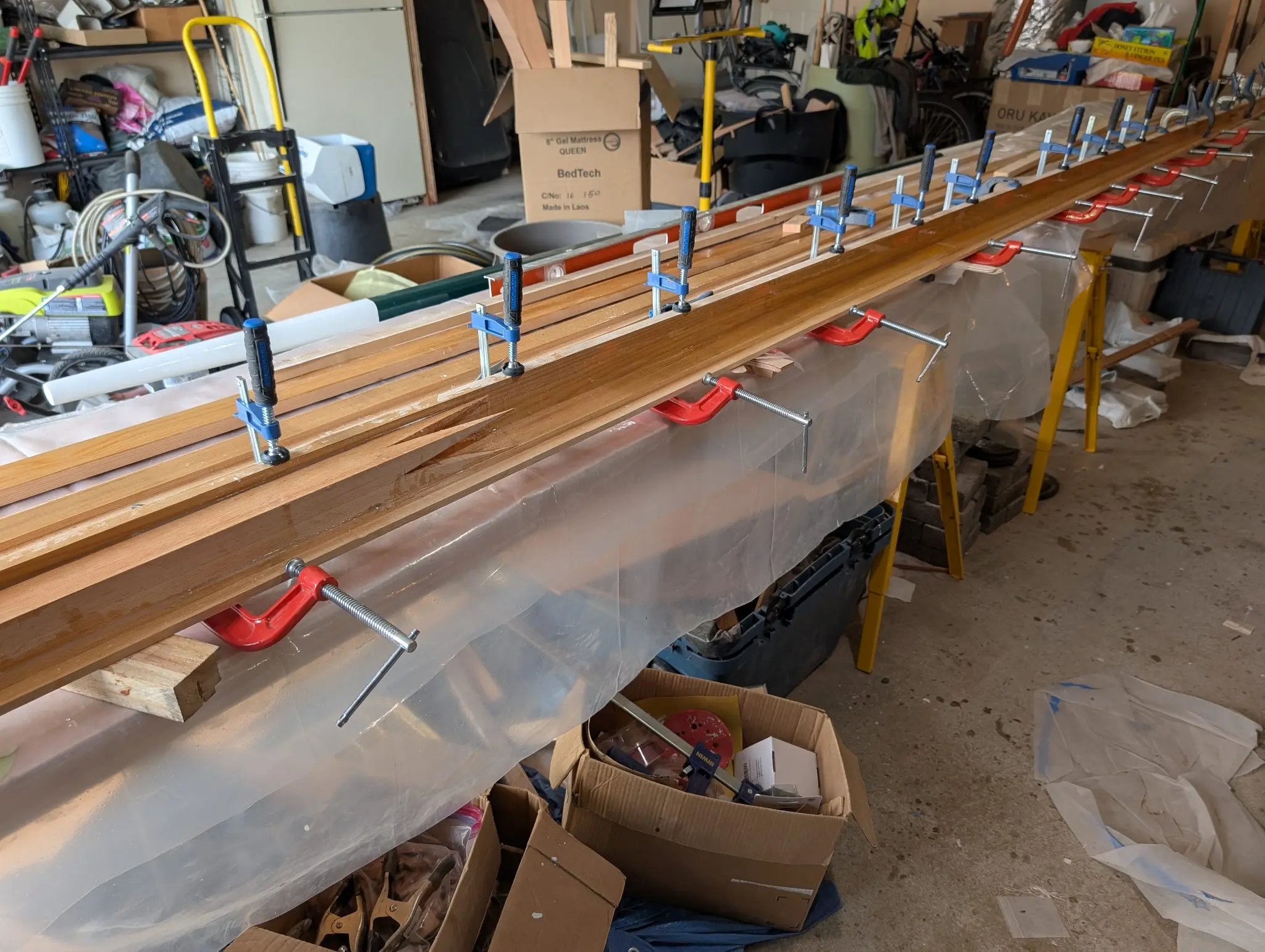
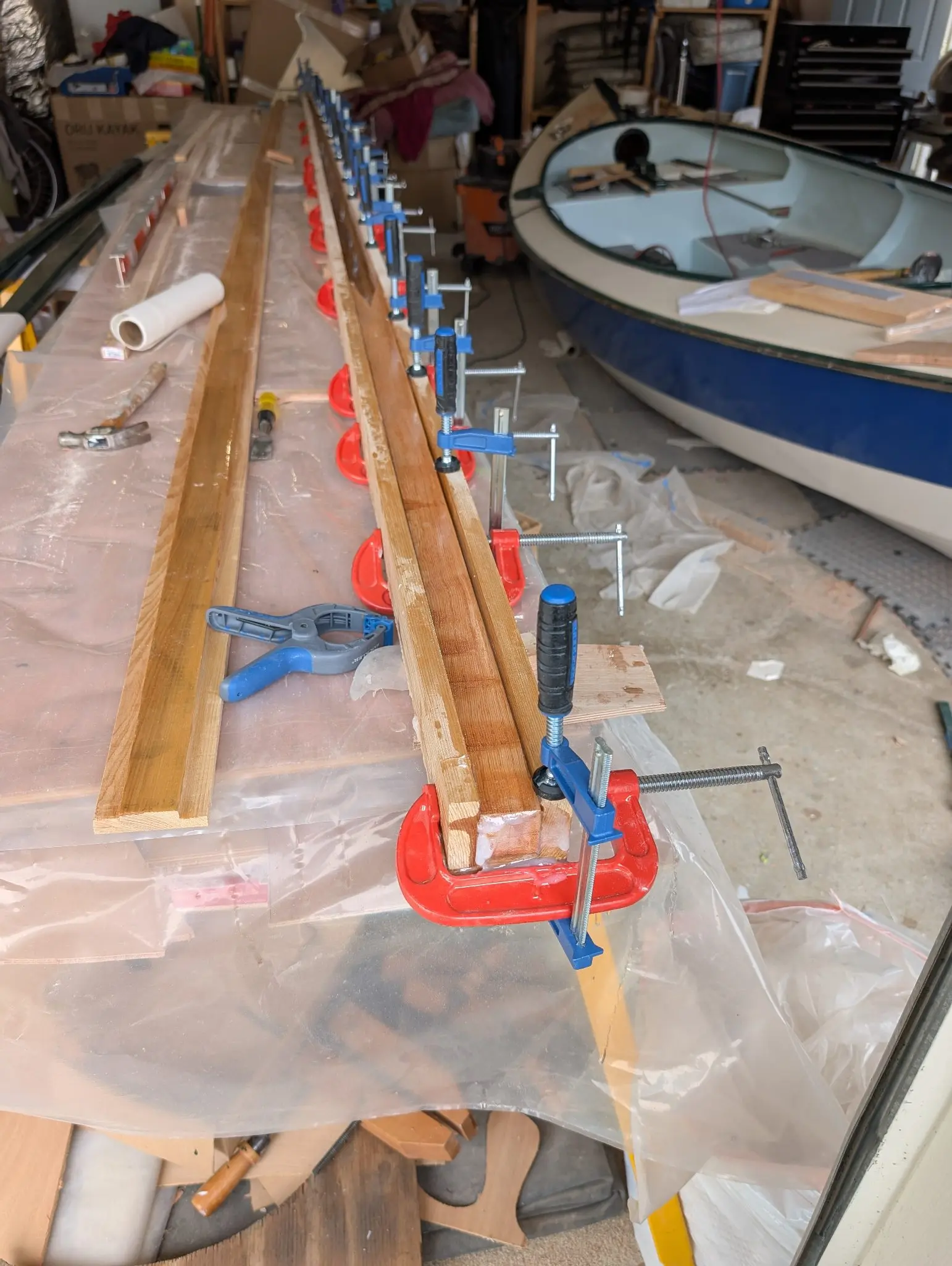
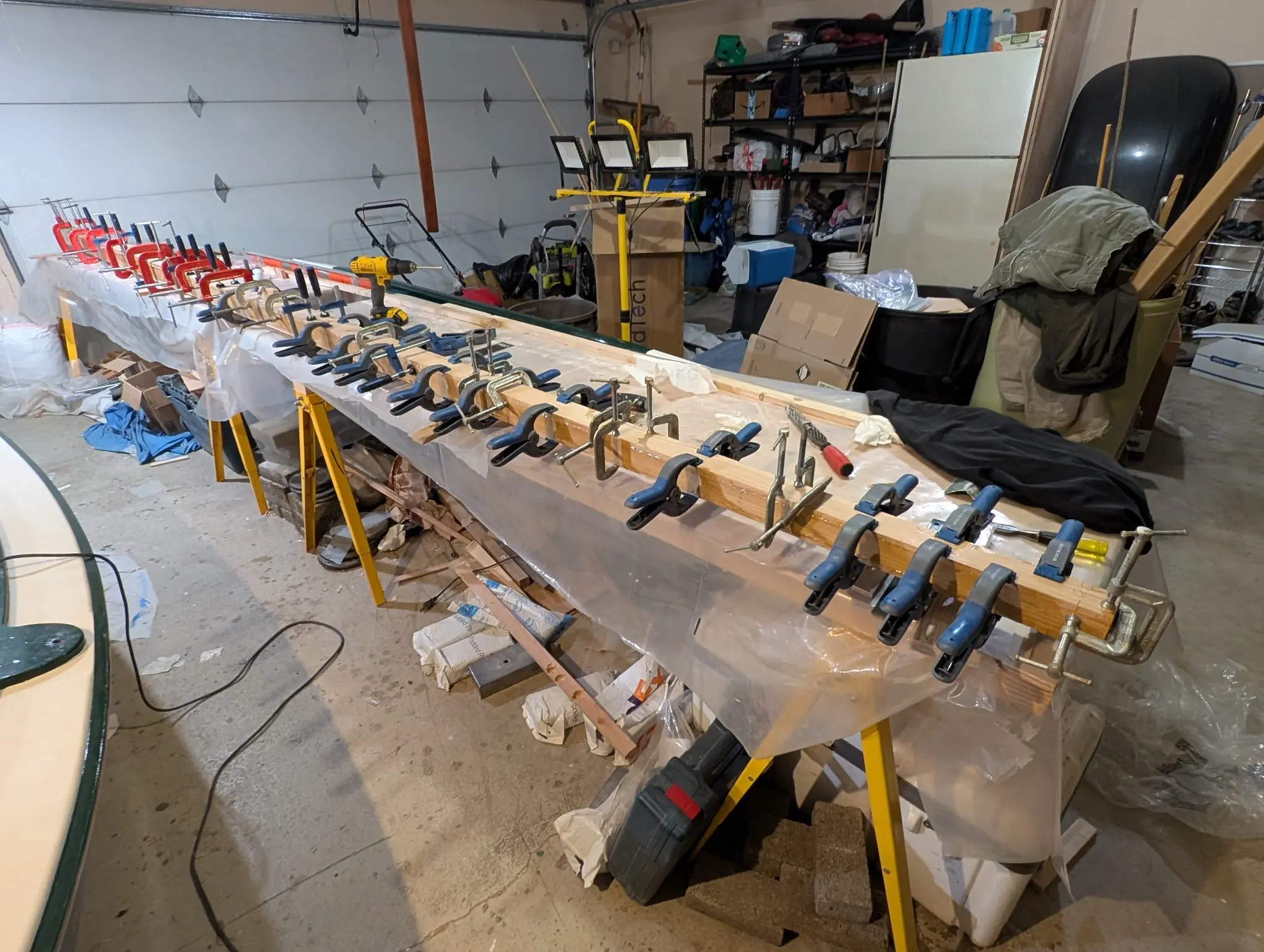
Any stitch-and-glue boat beyond 8' long requires two or more carefully shaped plywood pieces to be glued together to form one long strake. Pygmy used to use just flat butt joints. CLC uses puzzle joints, which facilitate aligning the planks lengthwise and holding them in place while the epoxy cures. Careful attention must be paid to leveling the joint so there is no vertical misalignment. Here is the number one plank being joined.
Photo 1 Photo 2 Photo 3
Chapter 03
Strongback & Molds
Building the strongback or ladder frame and setting up station molds.
1 dayfrom October 2023
30 Oct 2023Strongback & Molds
Attaching the deck cleats to the frames
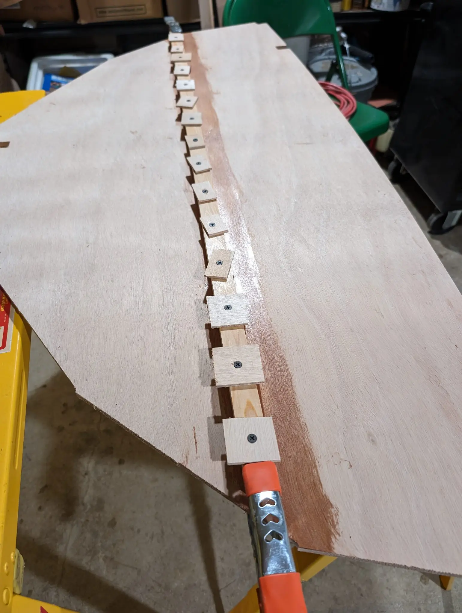
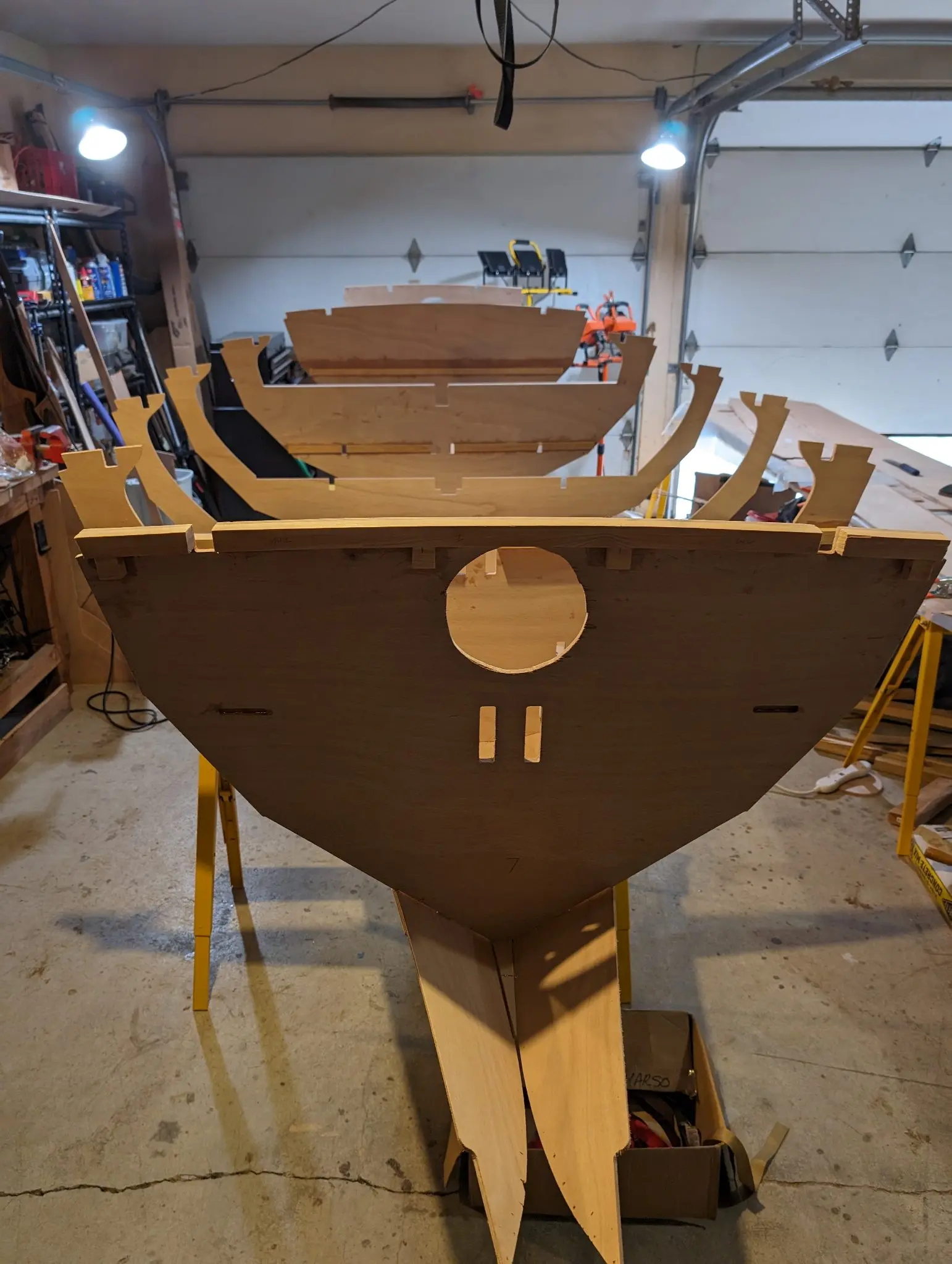
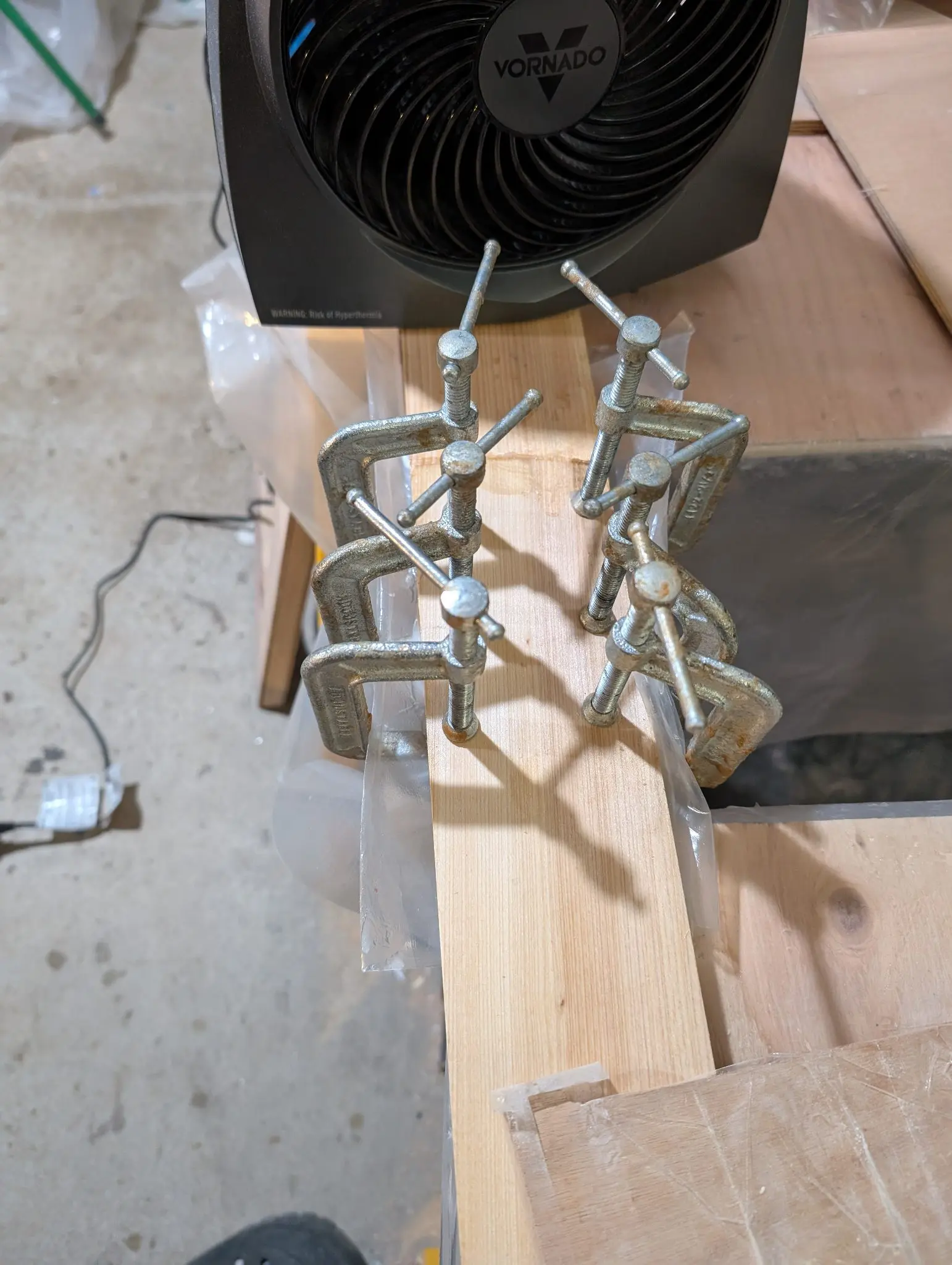
There are 7 frames in the boat. All the frames have cleats glued to them to support the decks. The main deck is cambered athwartship, so the cleats have to be bent or shaped in some way to support the cambered deck. I did this by attaching small blocks to the frames and using those to bend the cleats into shape with C-clamps. I considered gluing the cleats onto the frames without bending them, but there was enough camber that I would have planed away more than half of the cleats at their ends. Some of the cleats had to be installed in places my clamps would not reach so I just screwed them into place temporarily.
Photo 1 Photo 2 Photo 3 Photo 4
Chapter 04
Stitch & Assembly
Wiring or clamping the hull together and getting it fair and true before glue.
13 daysfrom November 2023
6 Nov 2023Stitch & Assembly
Start planking the boat
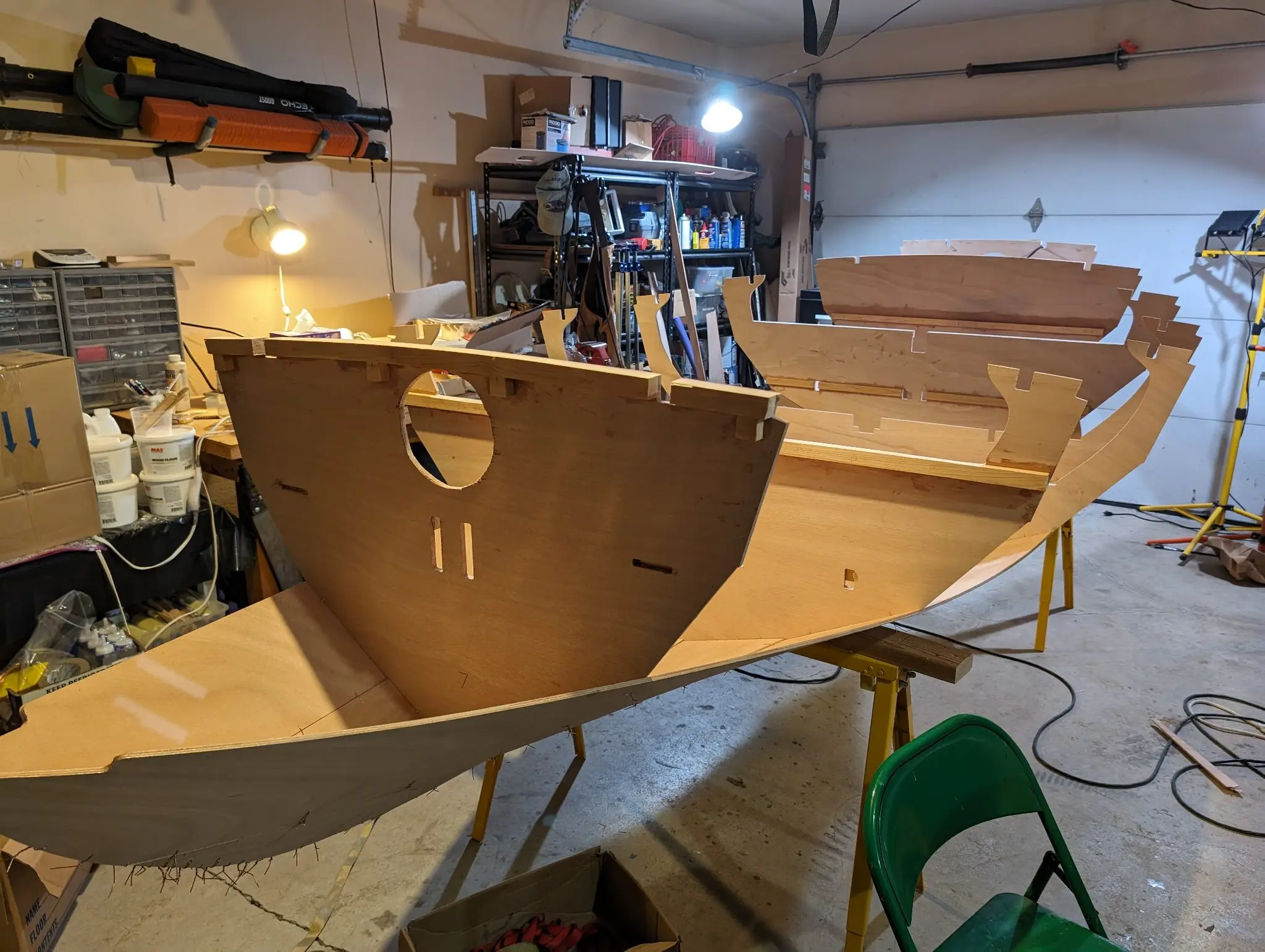
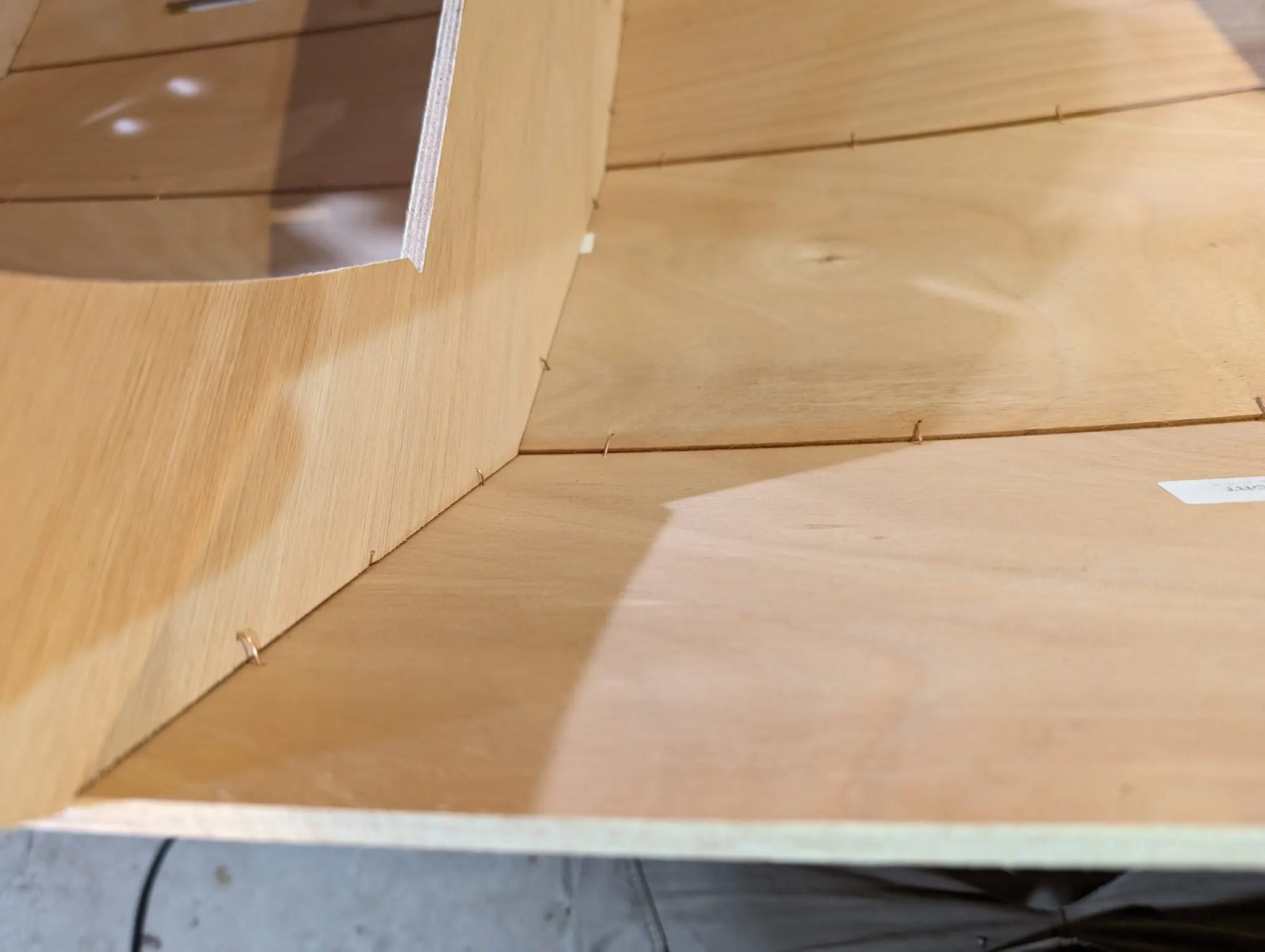
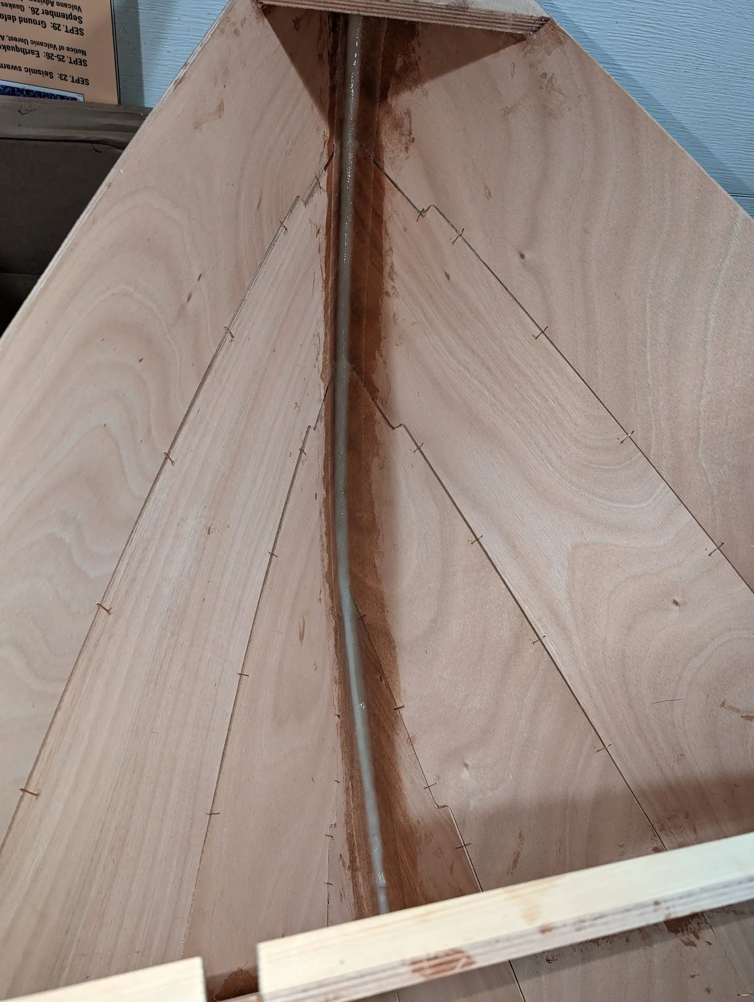
Here I have begun to attach the first panels to the keel panel with copper wires. The whole assembly is wobbly and fragile at this point. Getting it into some semblance of its final shape is what is important here. Final alignment is done later. This step is very tricky if you are working alone, as I was. Clamps, tape, bungee cords, and ratchet straps were all used to get things in place for stiching.
Photo 1 Photo 2 Photo 3
12 Nov 2023Stitch & Assembly
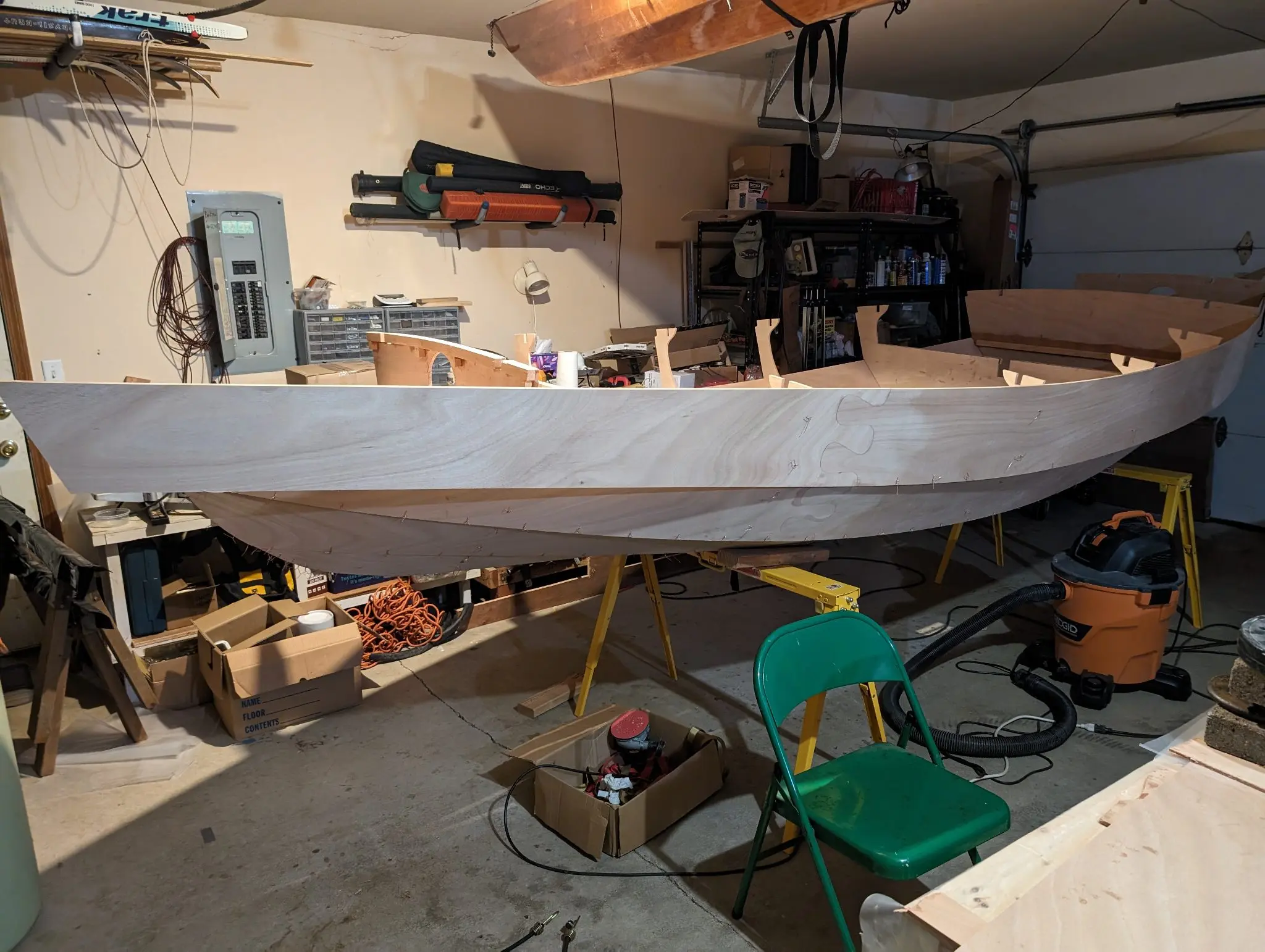
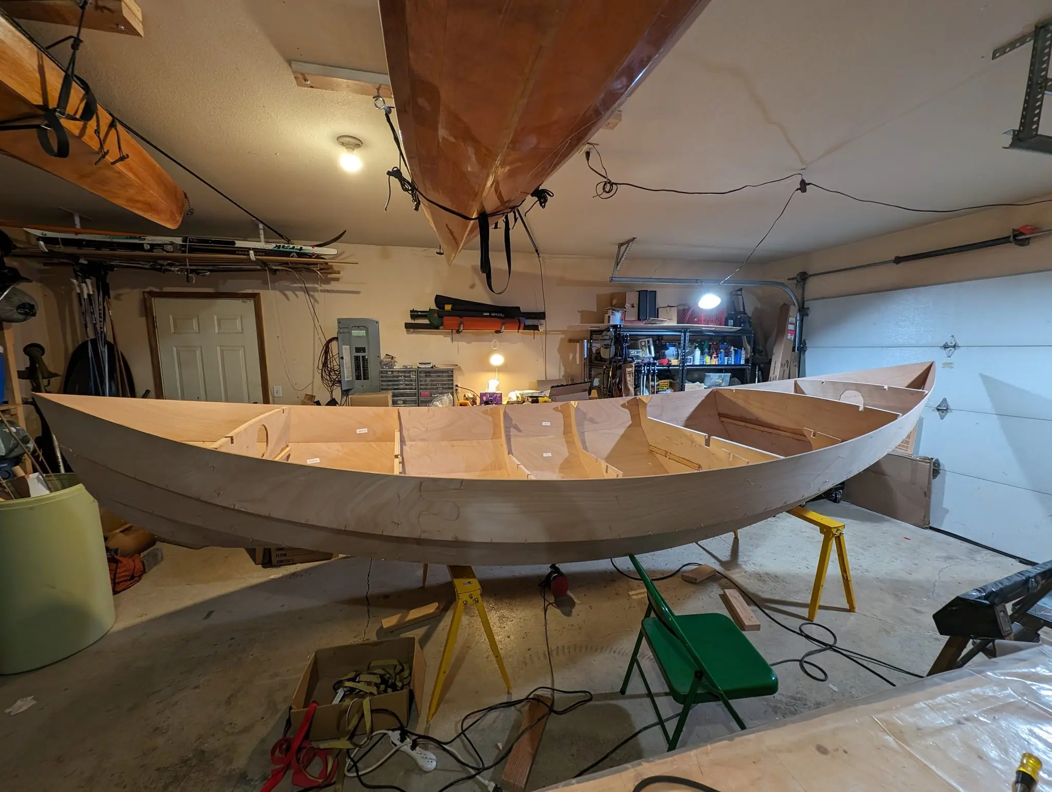
Planking the hull
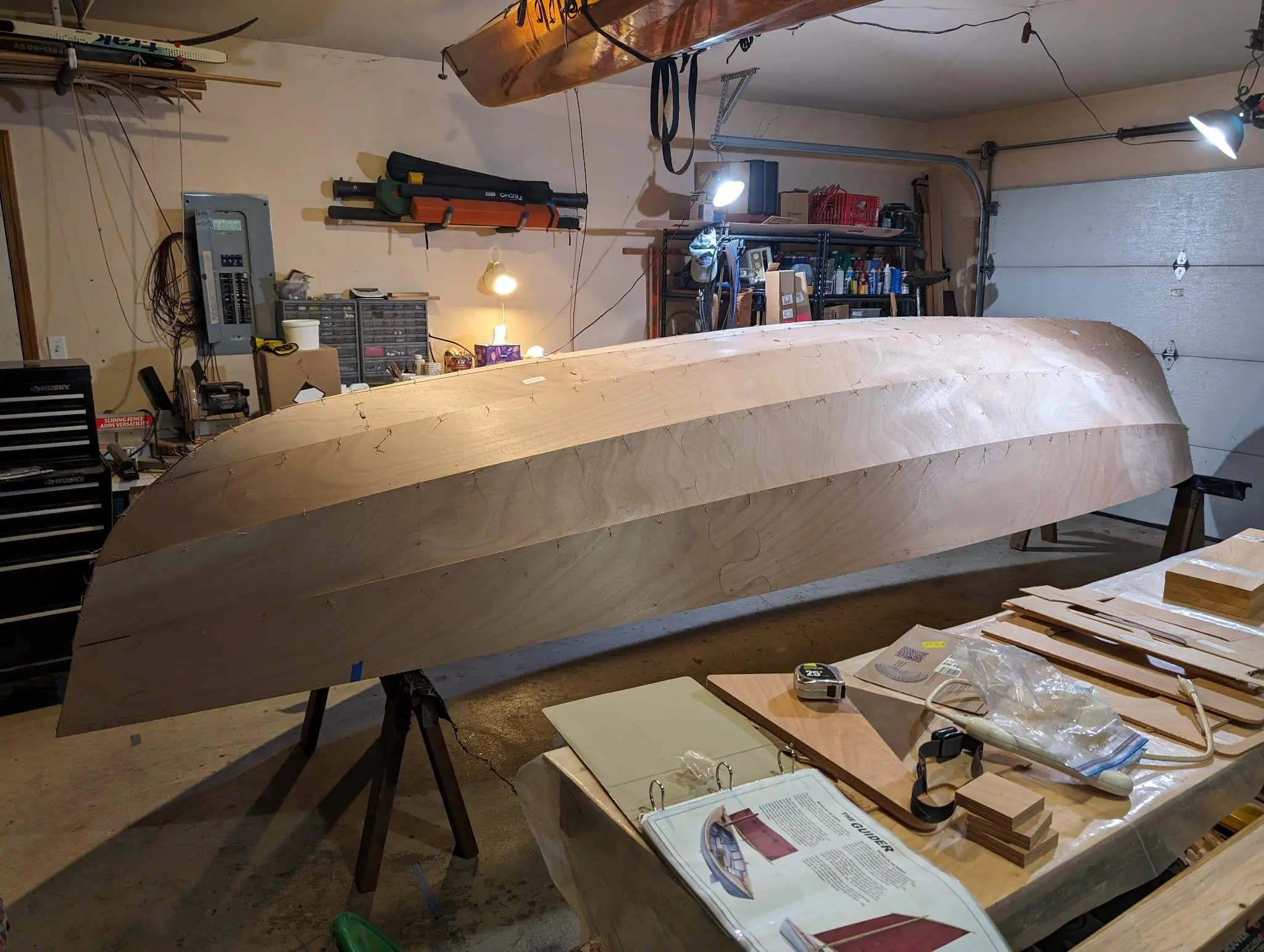
Once the first plank is in place and fairly solid, the rest of the planks can be wired on pretty fast. The whole thing starts to look like a boat. It gives you hope that you will get through this build quickly. This is deluded thinking. It's exciting to see, but it is just a tiny part of the work to come. Here you can see some of the details of wiring planks on. In this design, there are 4 hull panels in addition to the keel plate.
Photo 1 Photo 2 Photo 3 Photo 4
15 Nov 2023Stitch & Assembly
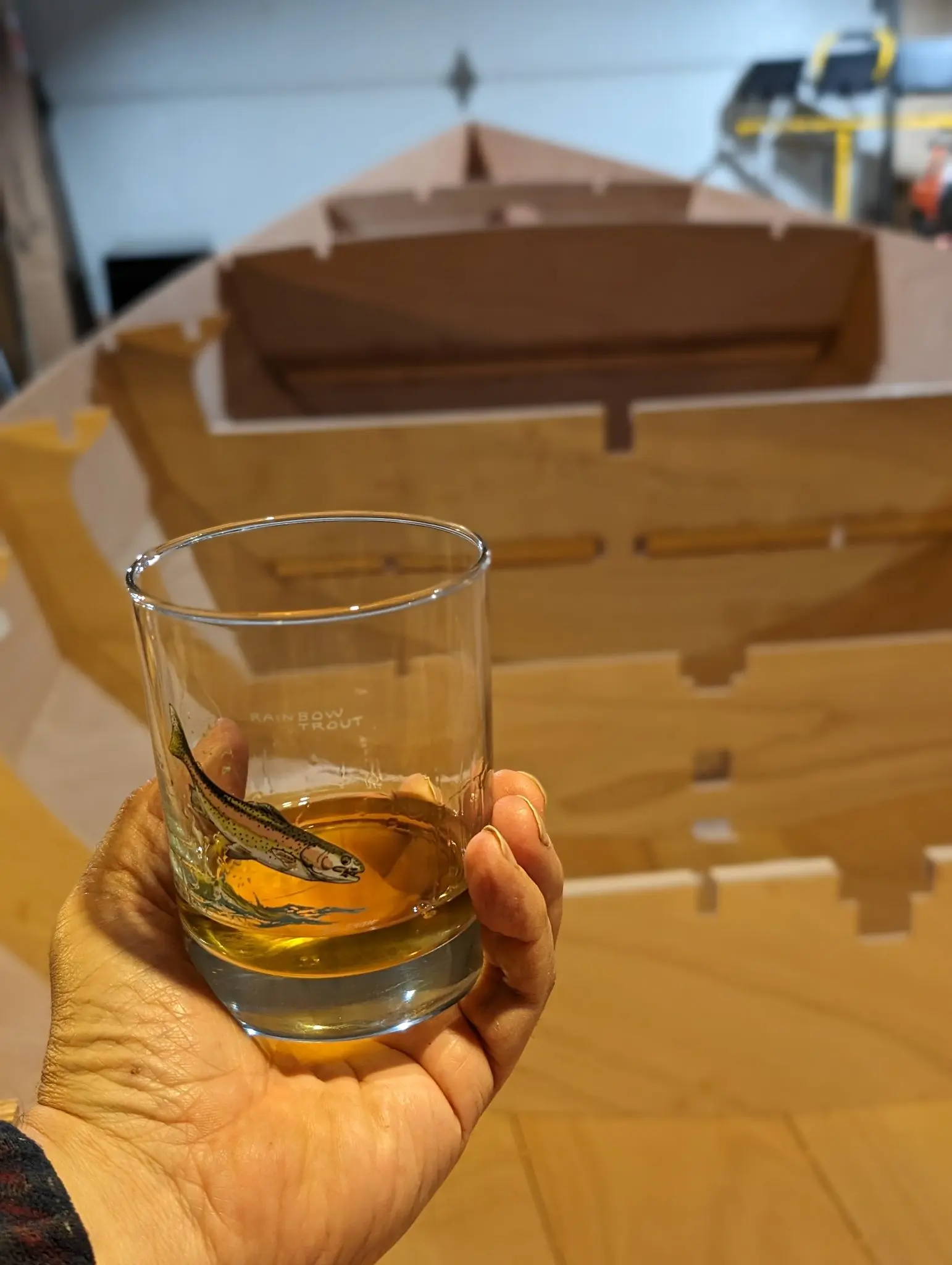
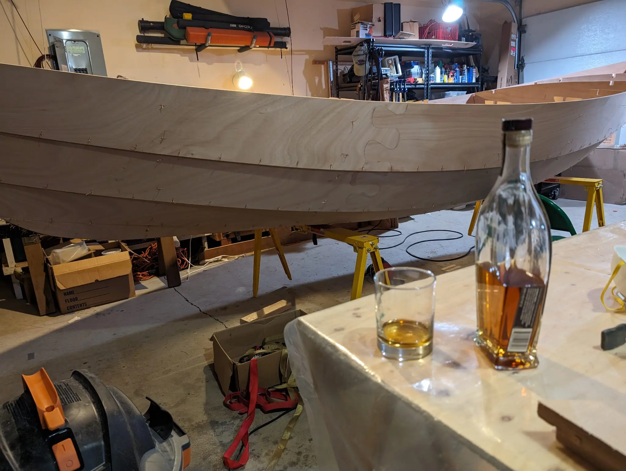
Whiskey plank
It's traditional among boat builders to celebrate attaching the final plank by sharing a whiskey. In traditional boatbuilding, fastening the final plank to the hull is a little more significant than it is in stitch-and-glue projects. Here, the hull has its shape, but there is a huge amount of work to go on the hull before one really deserves a whiskey. Nevertheless, it's exciting to see the hull take shape, and that should be celebrated.
Photo 1 Photo 2 Photo 3
17 Nov 2023Stitch & Assembly
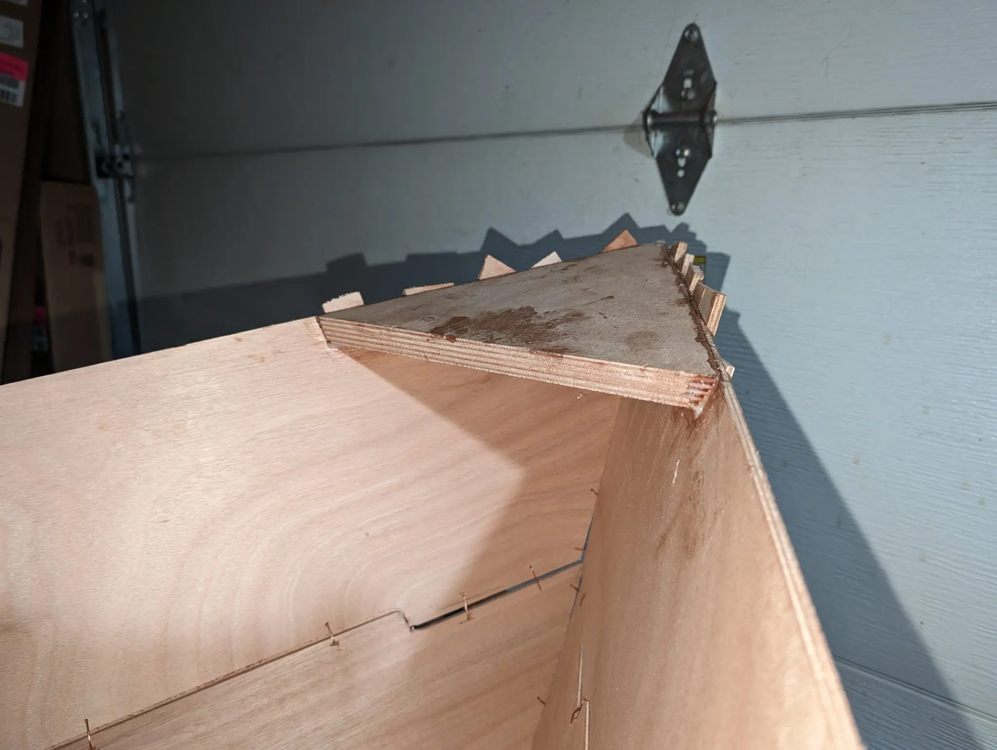
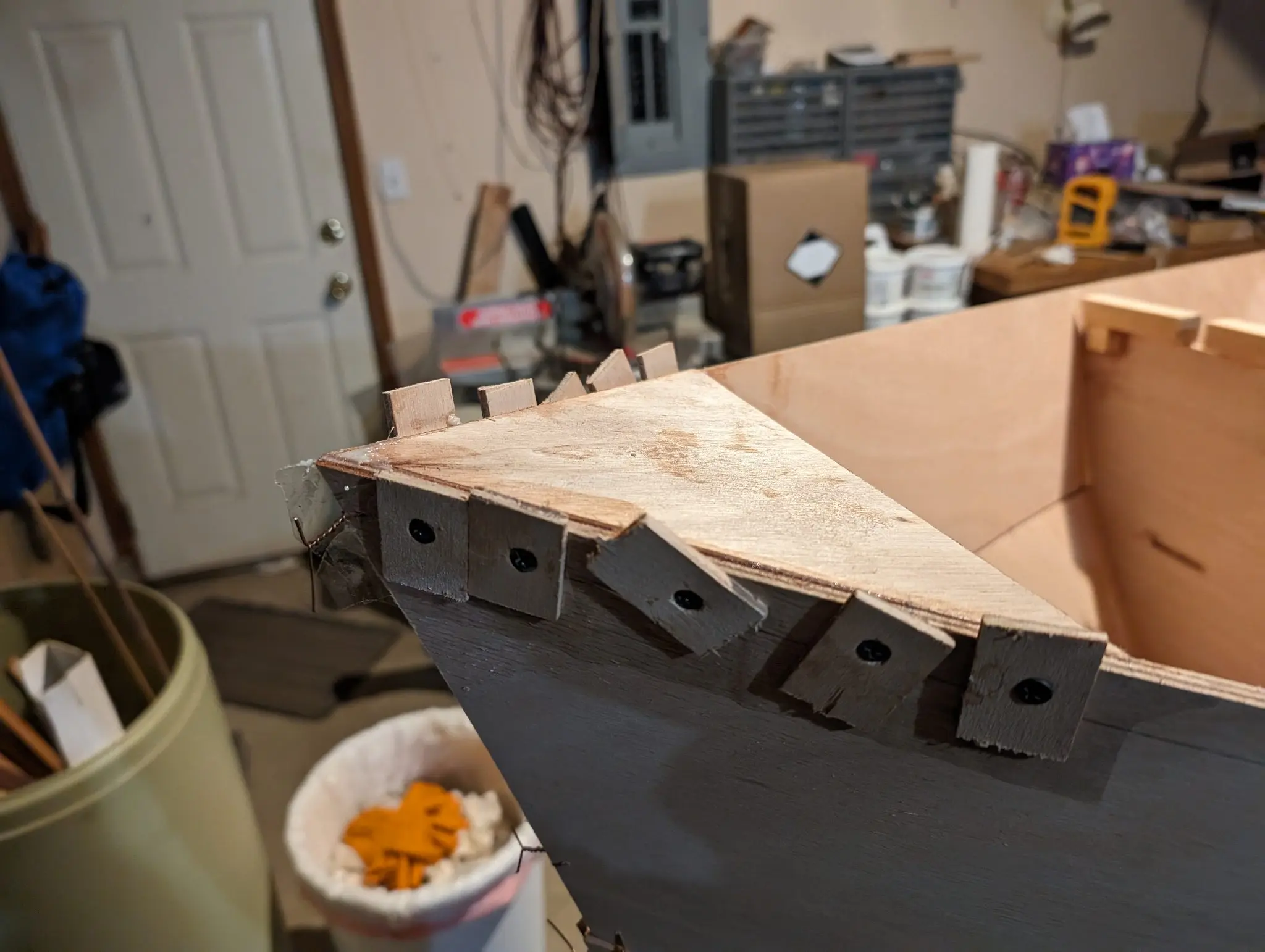
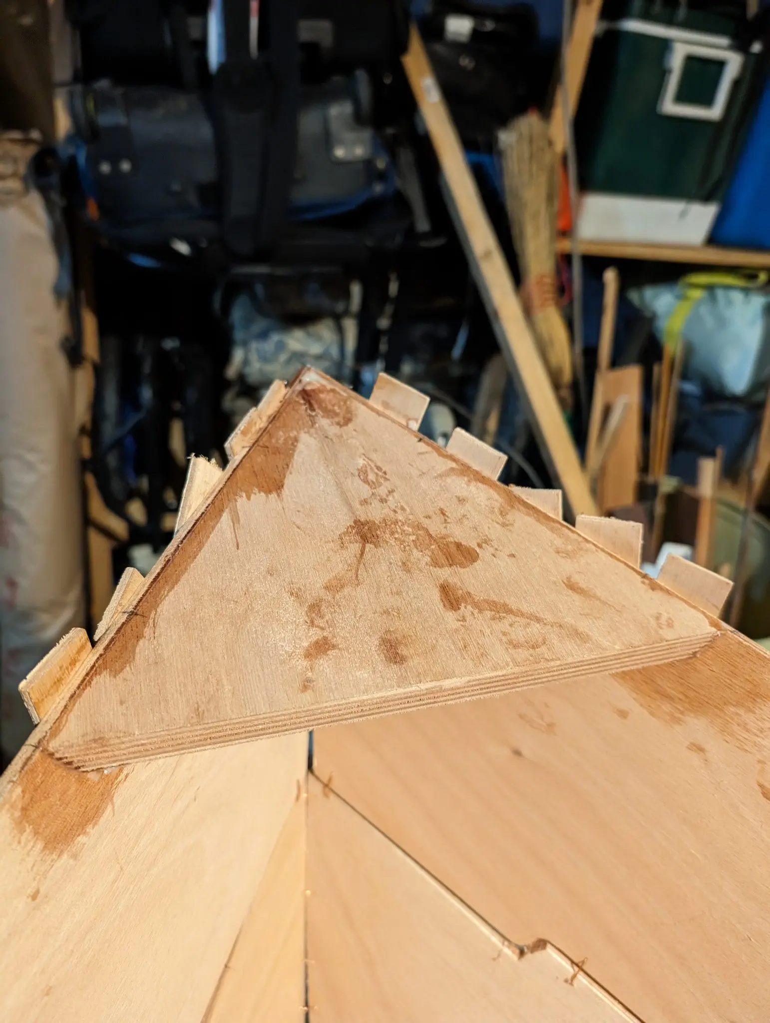
Breasthooks bow and stern
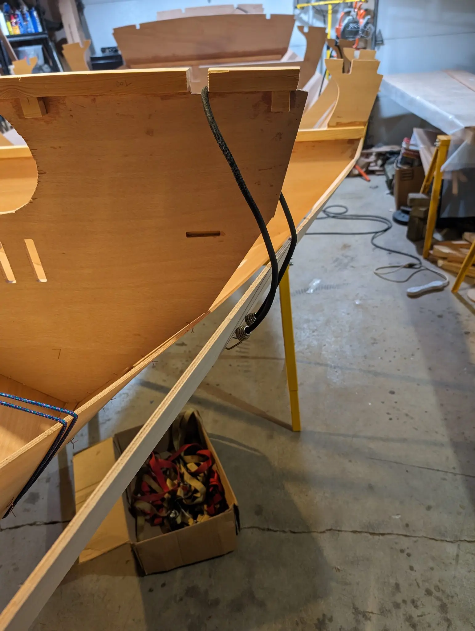
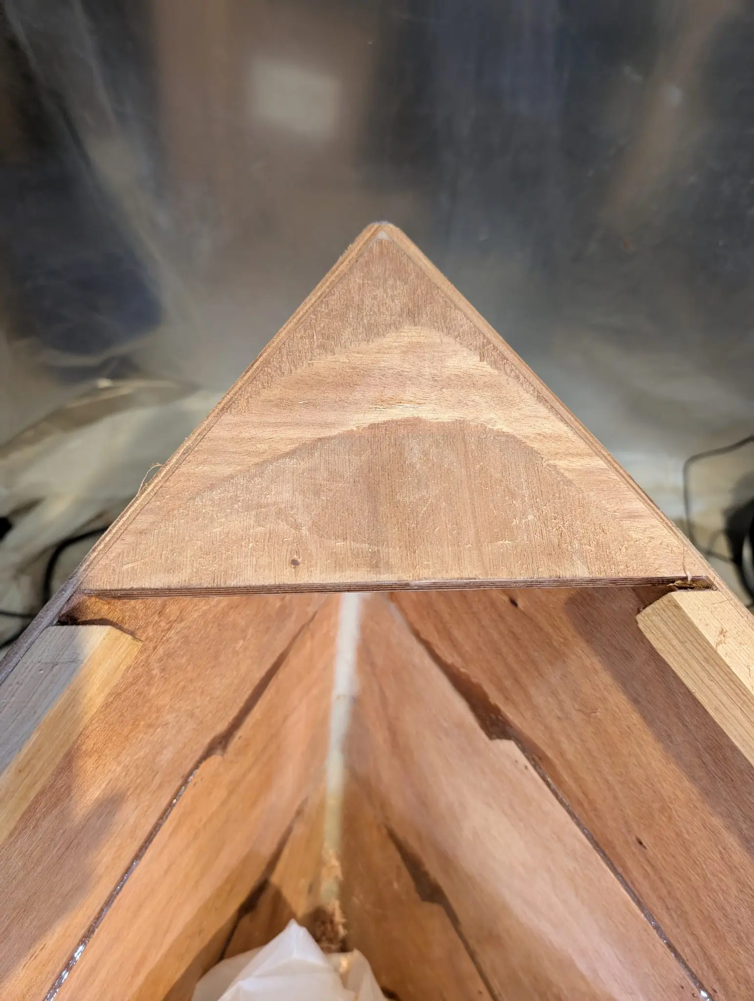
Bow and stern breasthooks are smallish triangular pieces of wood that reinforce the ends of the boat and provide a surface to support the deck in both areas. The CNC machine that CLC uses to cut its pieces only cuts normal to the surface of the work, so these pieces must be shaped to fit. It's a bit tedious to do this shaping with a lot of plane and rasp work with many dry fittings. The breast hooks are in a place where it is awkward to clamp them so they are screwed in temporarily while the glue cures.
Photo 1 Photo 2 Photo 3
22 Nov 2023Stitch & Assembly
Tacking the hull together with epoxy
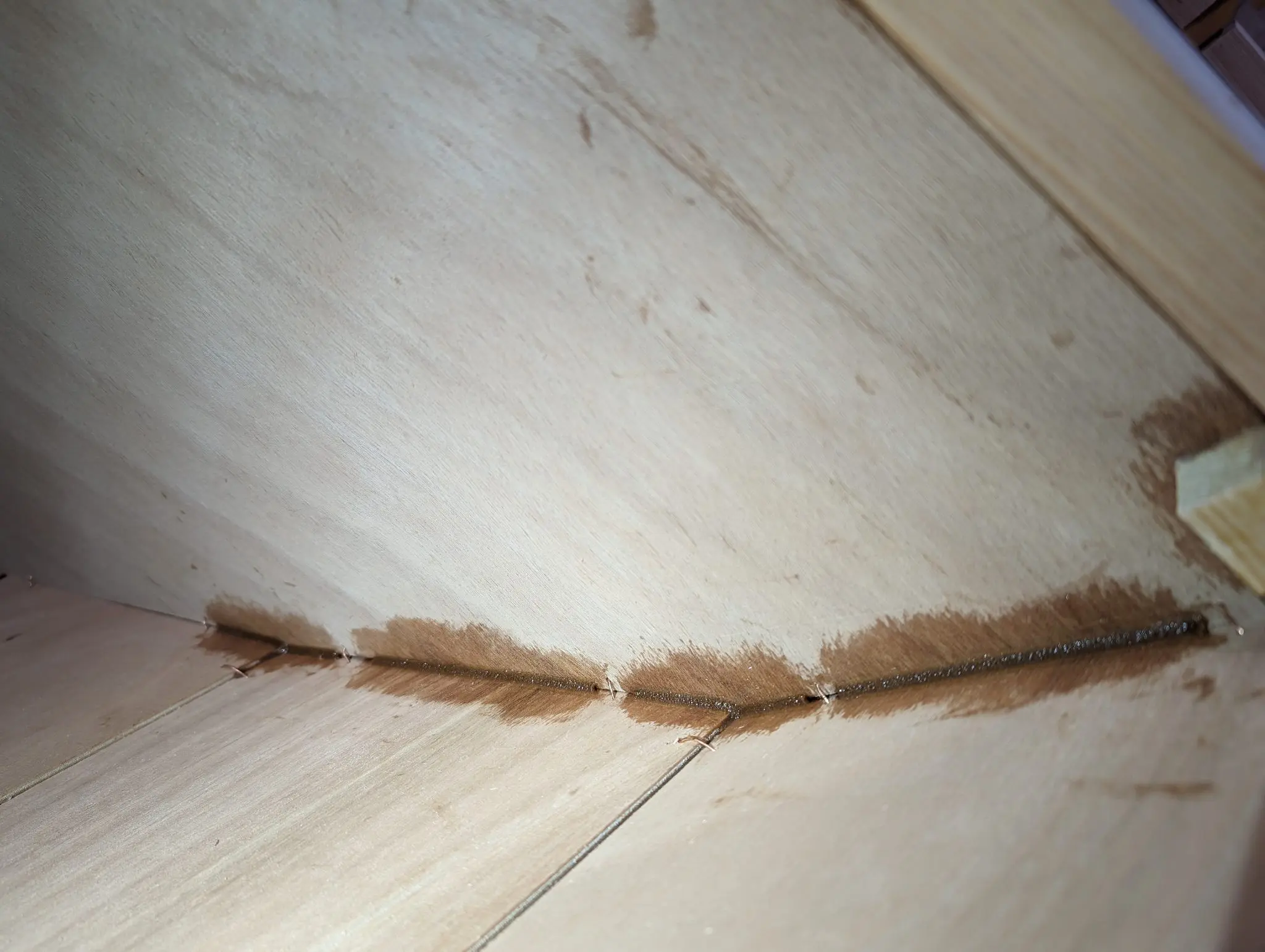
After the whiskey buzz wears off, the rest of the work on the hull begins. Here I am tacking the frames to the hull panels by placing small fillets of thickened epoxy into the joints between the wire ties. The idea is to then come back, remove the wires, and add more fillets of thickened epoxy in the spaces where the wires were. I think if I were to do this again, I would just use a screwdriver to press the wire bridges into the angle and fillet right over the wires. On the outside, I would just snip the twisted ties off and sand them flush. Copper is plenty soft enough to sand. This would actually save a lot of time with filleting and pulling wires, but I guess it might look funky if you were finishing your hull bright. I will be painting my hull, so that isn't a problem.
Photo 1 Photo 2 Photo 3
22 Nov 2023Stitch & Assembly
Fillet the bow and stern seams
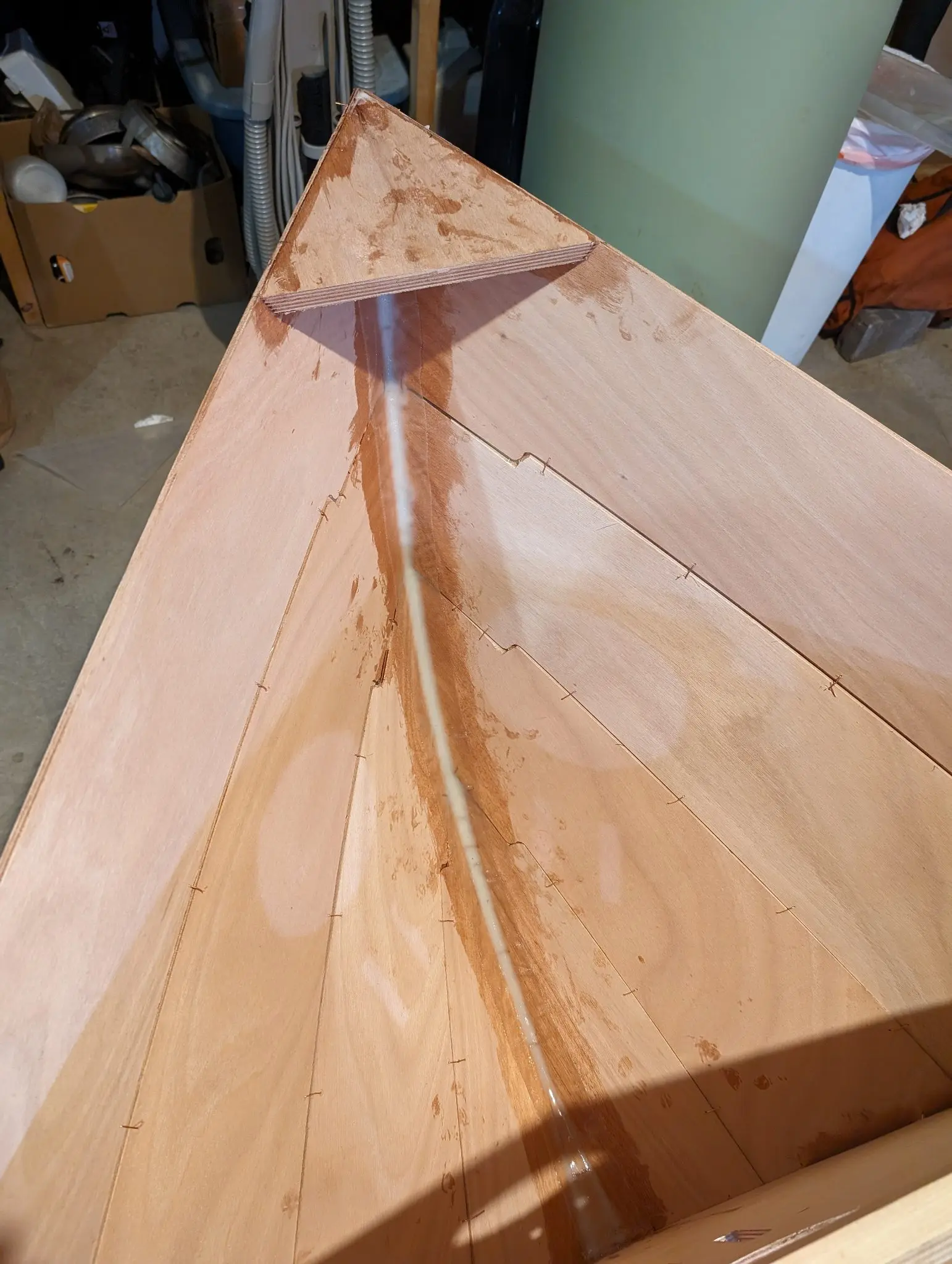
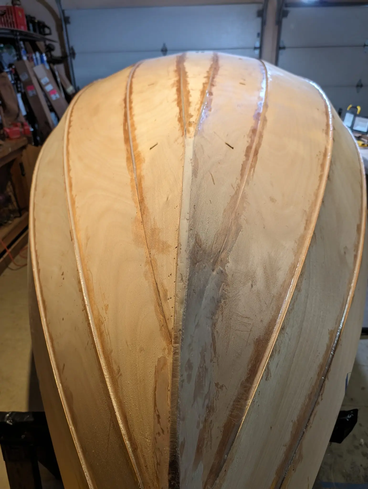
Fillet the bow and stern joints with 3" of 9 0z. fiberglass tape. Although the plans don't explicitly call for it, I went back later and applied a bigger fillet and a wider layer of 6 oz. fiberglass cloth that was also tied to FG sheathing on the interior of the hull in both locatioins. I don't think it's possible to make the bow and stern too strong.
Photo 1 Photo 2
14 Dec 2023Stitch & Assembly
Gluing the outside seams
Once the seams and frames are all tacked with epoxy on the inside, the boat is flipped and the same is done on the outside of the hull. The edges of the planks where they meet other planks are rabbeted to form a shoulder. When the planks are aligned properly, this creates clean contacts with an overhang at the junction. Small beads of thickened epoxy are injected into these shoulders between the copper stitches to glue the planks together. This is only to tack the planks together; a smooth fillet of thickened epoxy will be laid over these tacks later. Once these tacks are cured all the copper stitches are removed from the hull and a smooth fillet of thickened epoxy is laid down over the exterior seams of all the planks. Then the boat is flipped again to continue work on the inside.
Photo 1 Photo 2 Photo 3
8 Feb 2024Stitch & Assembly
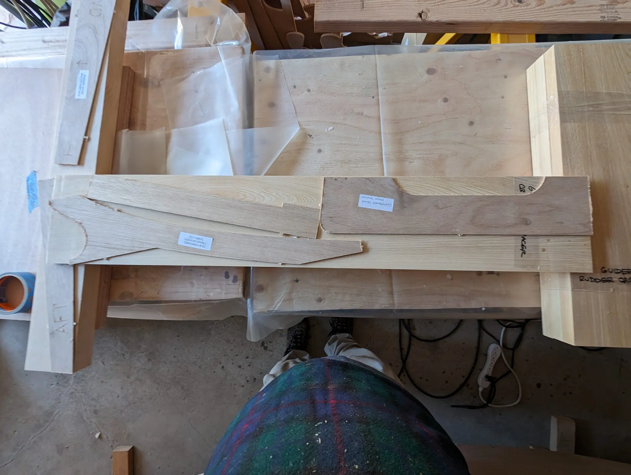
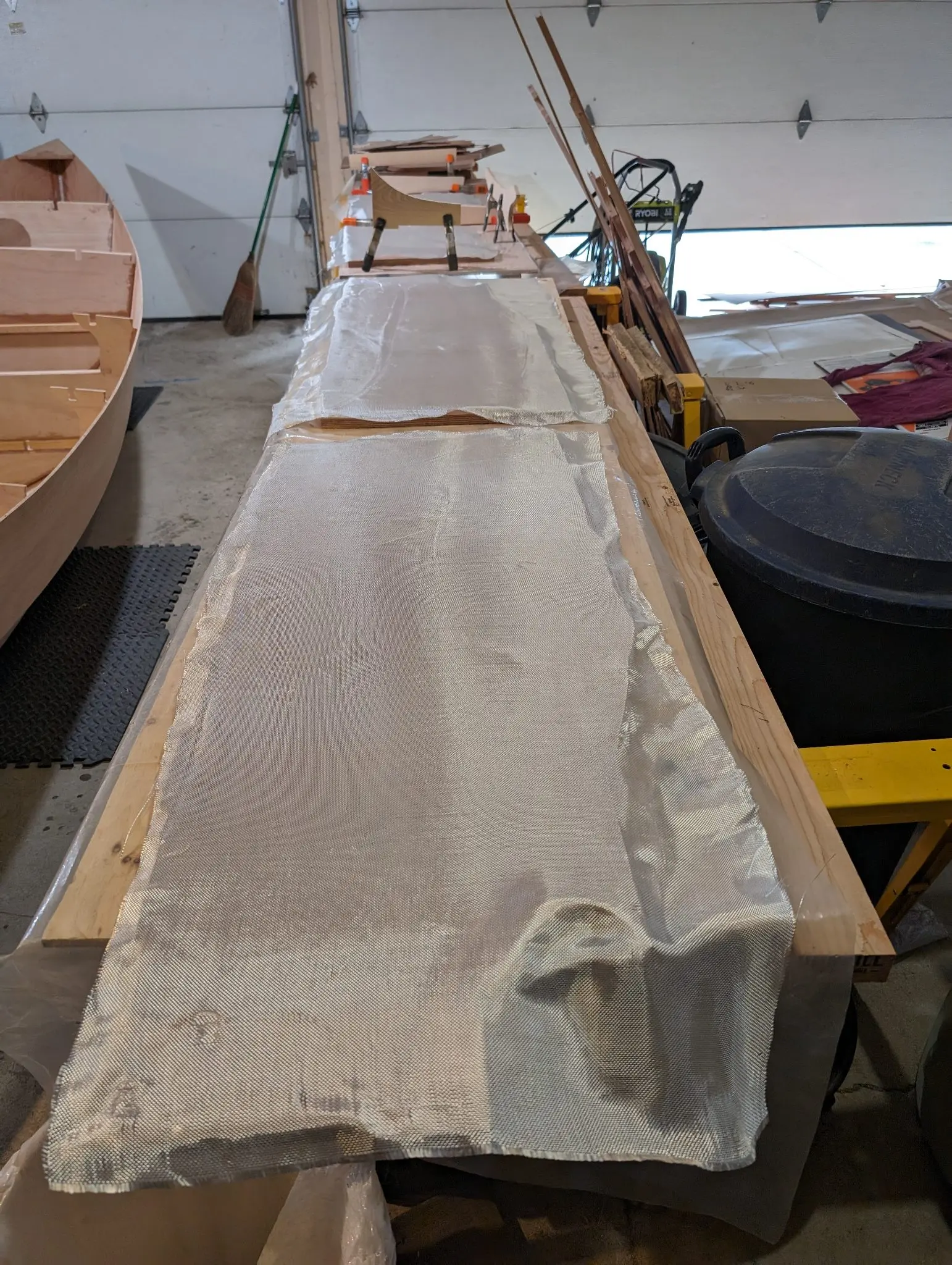
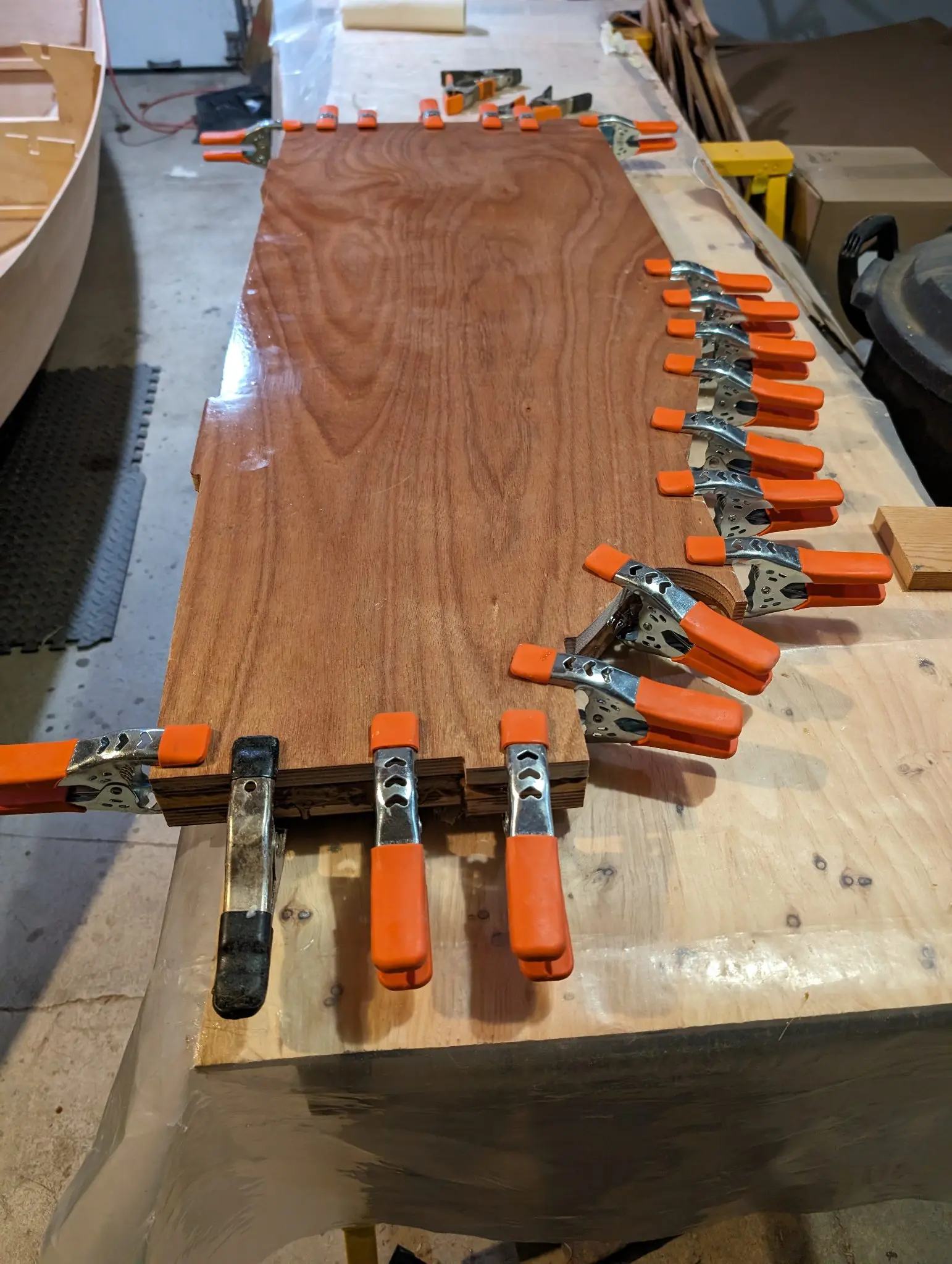
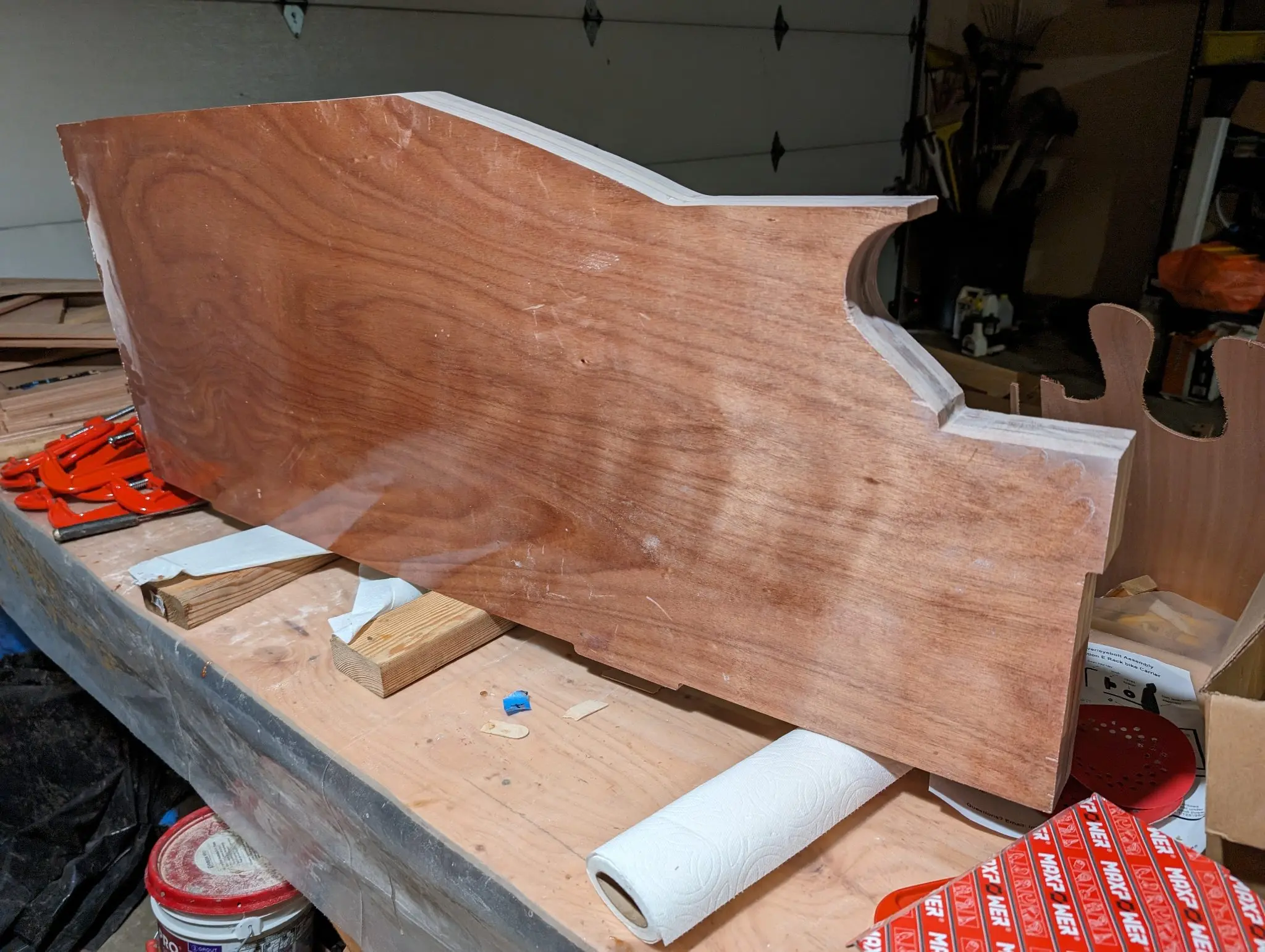
Building the centerboard trunk
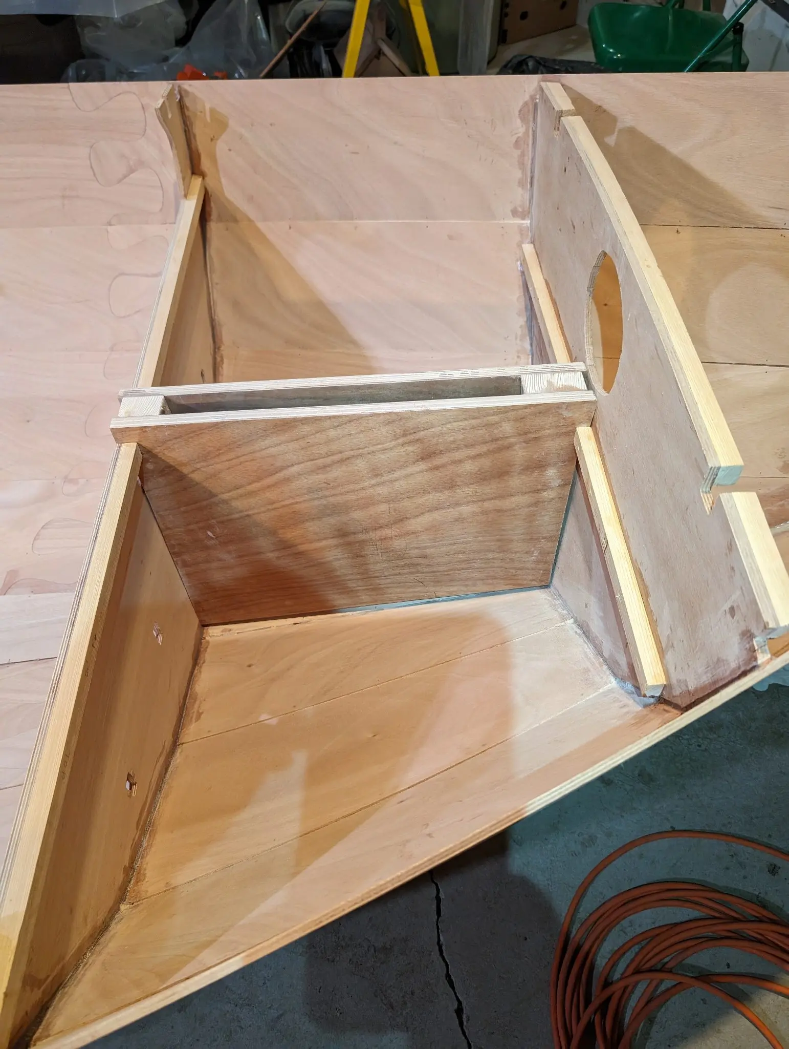
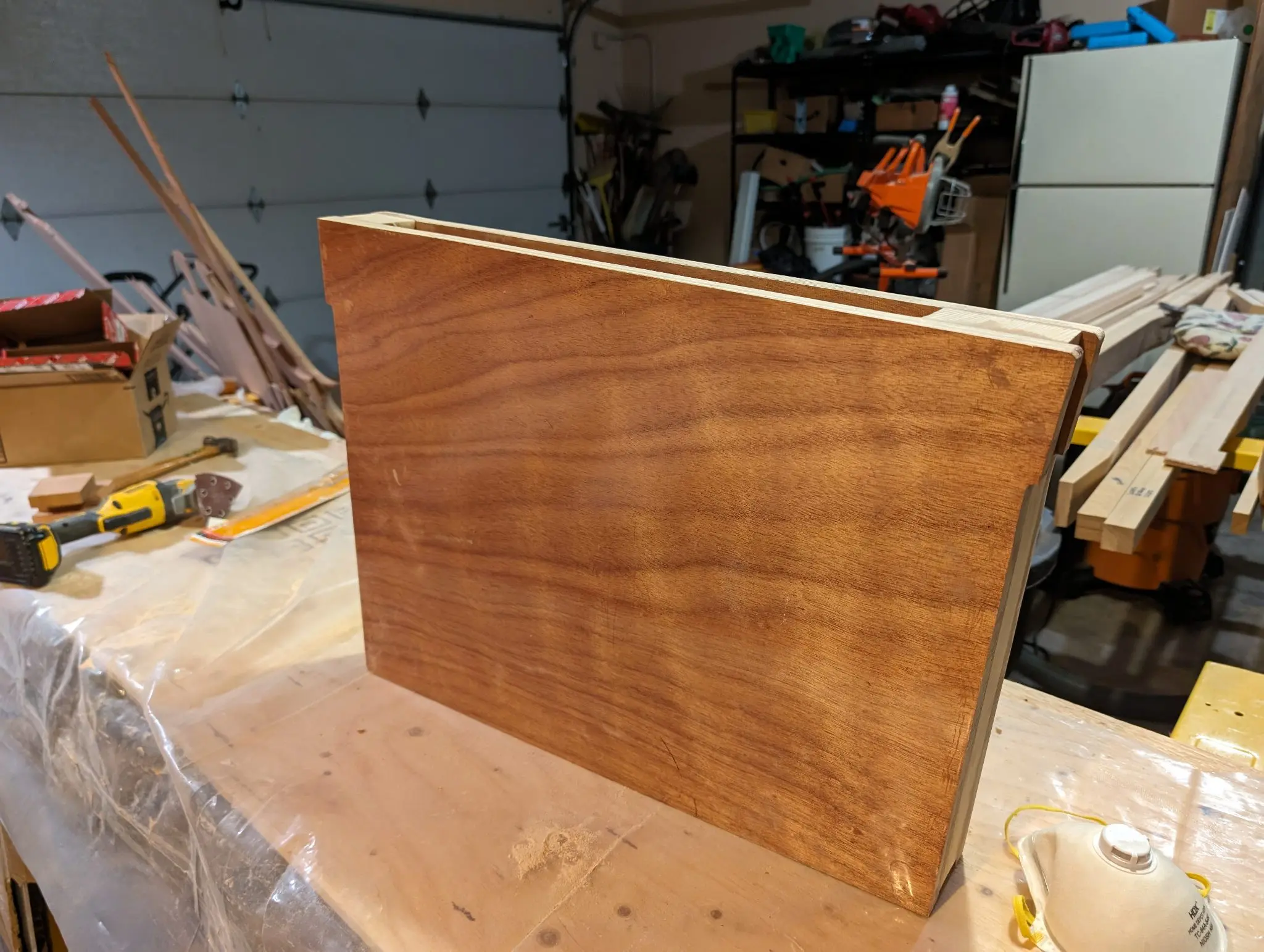
I built the centerboard trunk. CLC provides doorskin templates for cutting dimensional lumber (cypress) for the edges. It's fiberglassed inside and out.
Photo 1 Photo 2 Photo 3 Photo 4
24 Mar 2024Stitch & Assembly
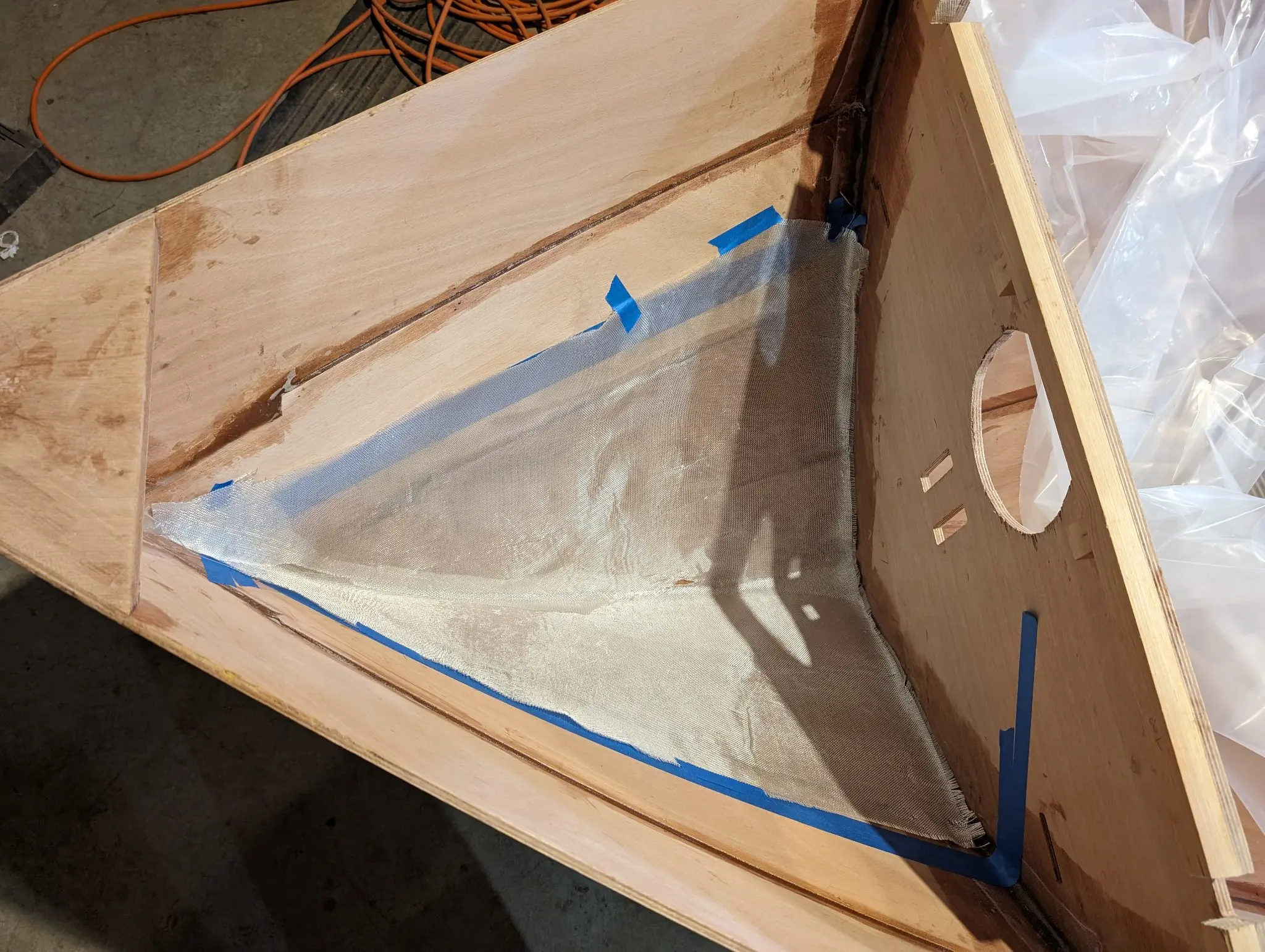
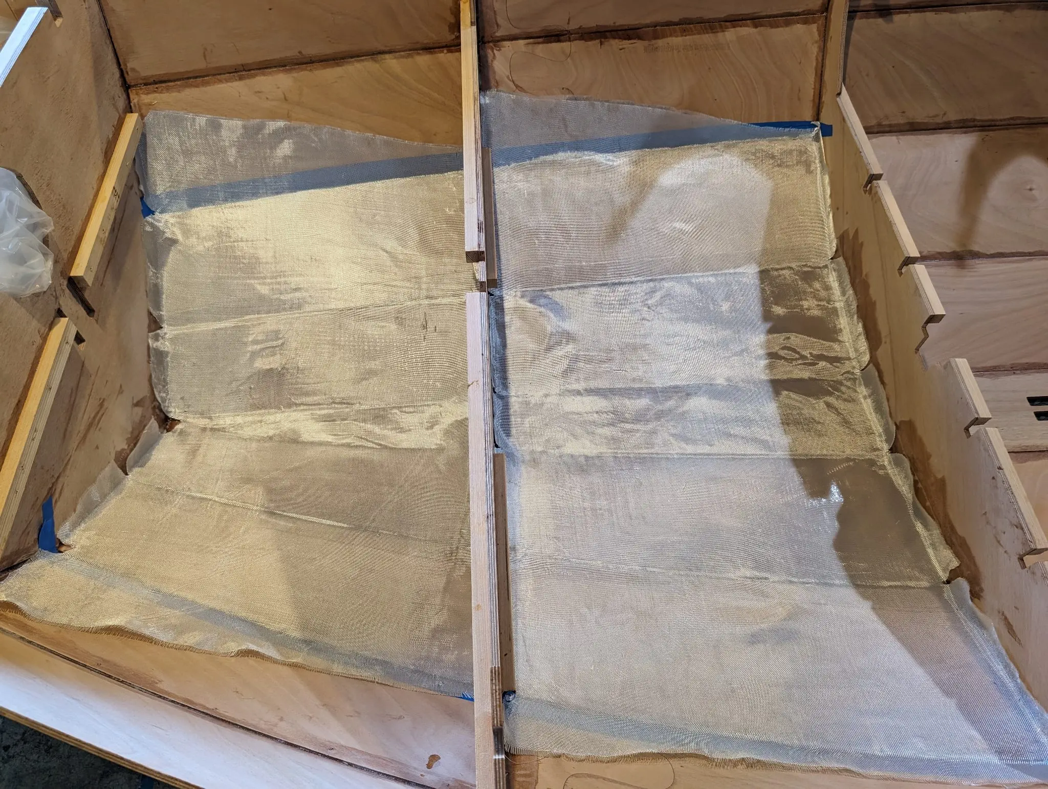
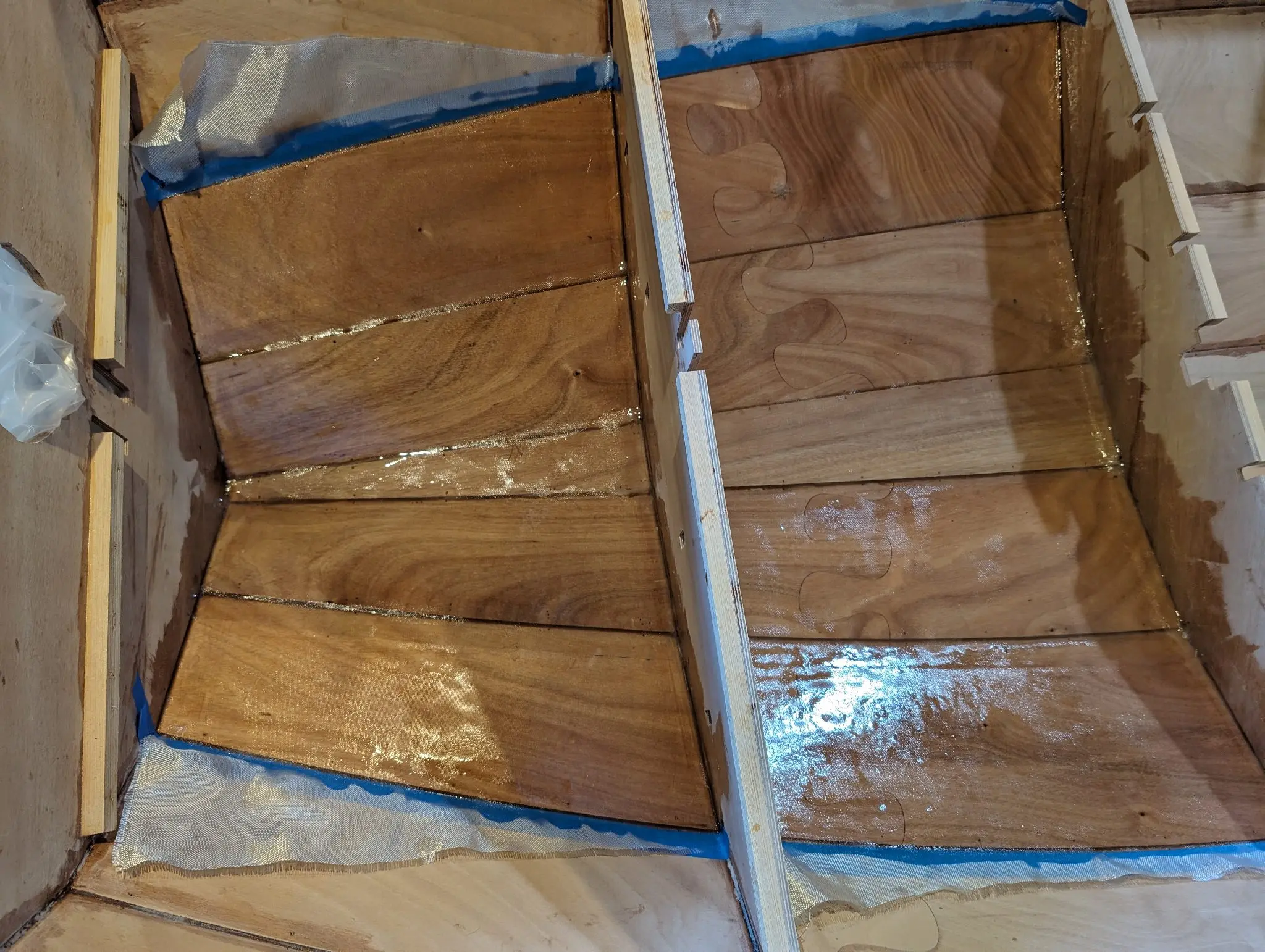
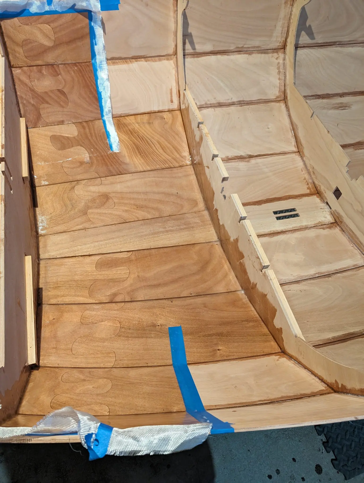
Glassing the hull interior
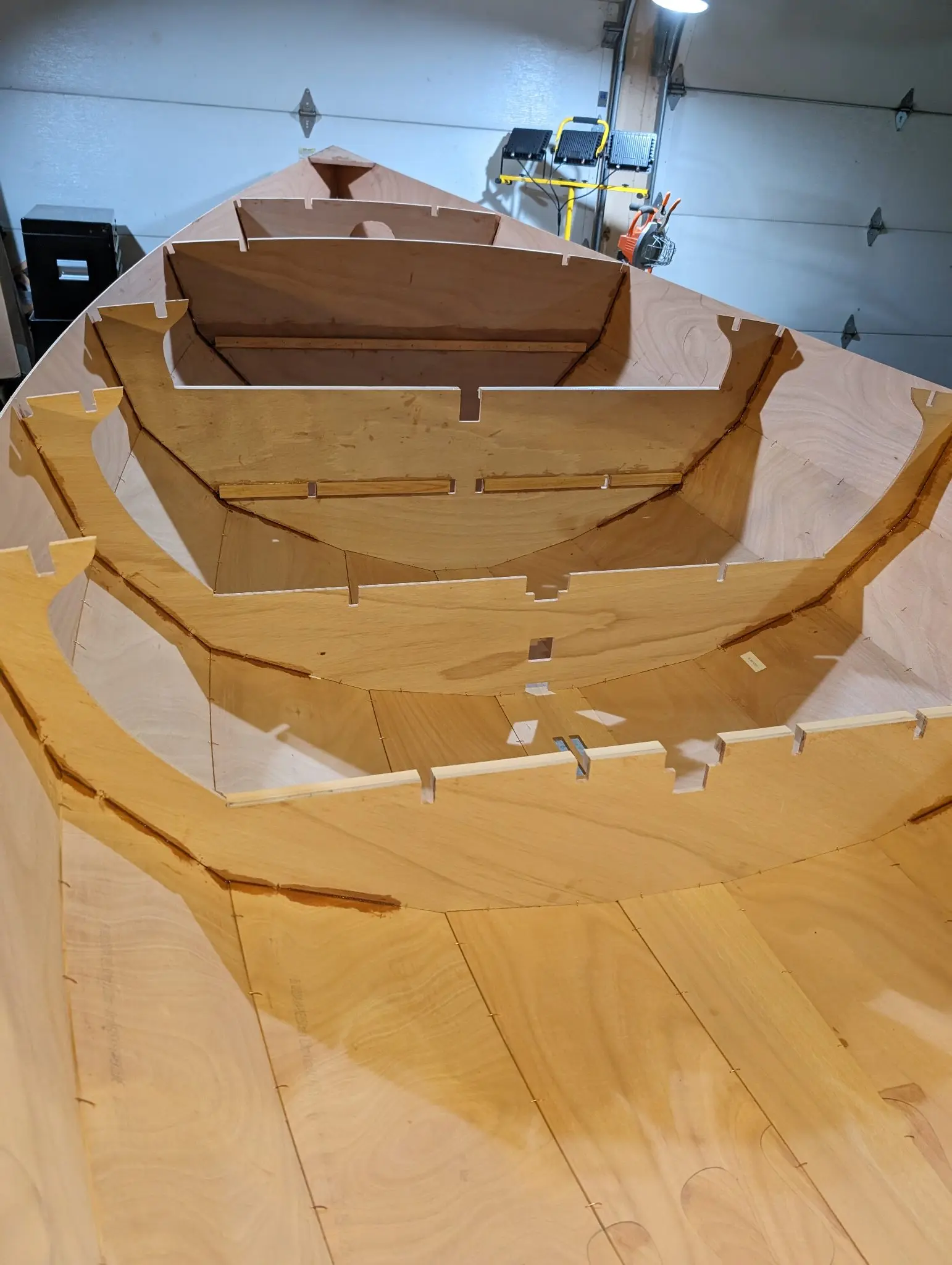
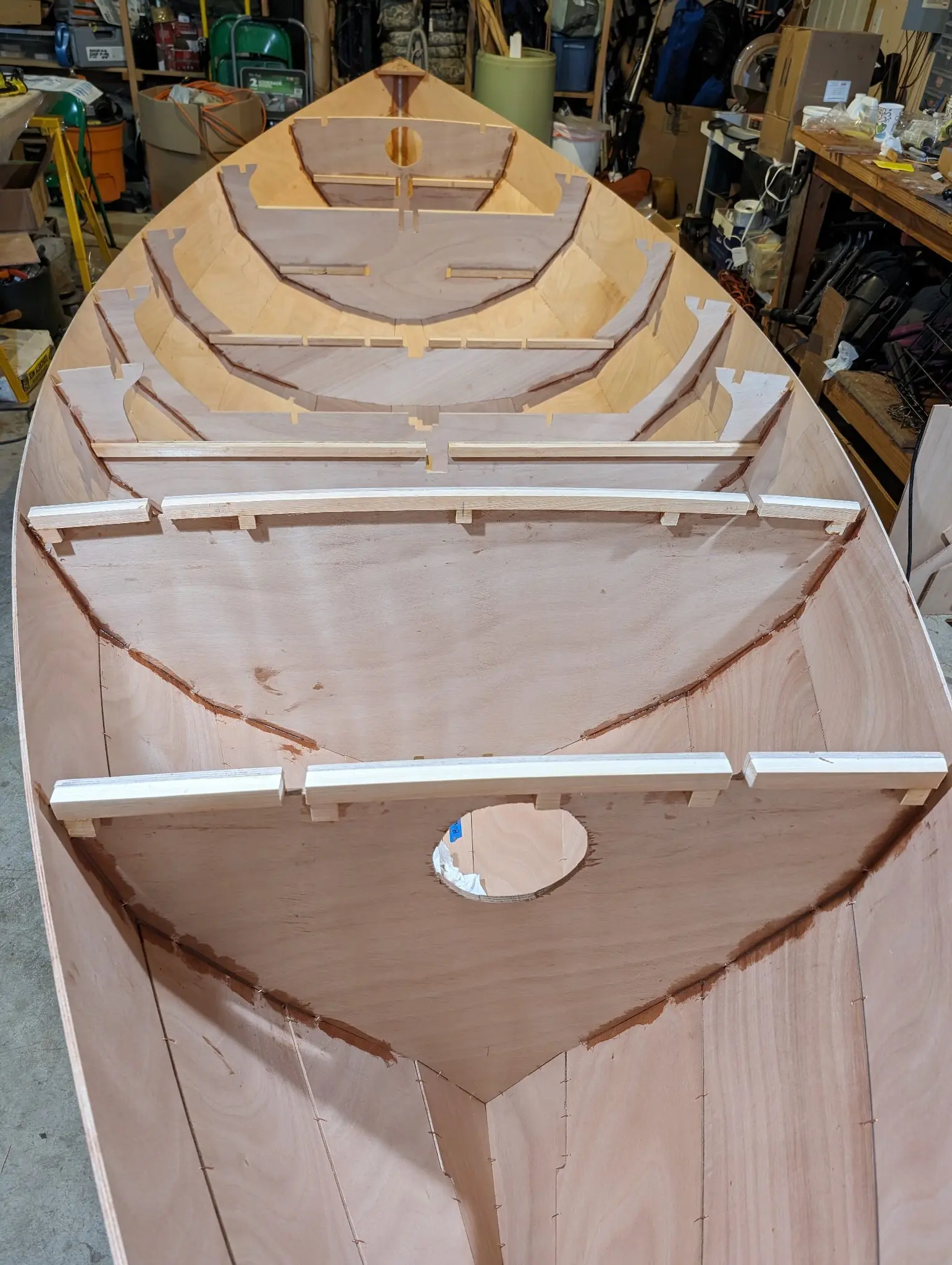
Fiberglassing the inside of the hull is a little complex because the frames are already in the boat. Each section of cloth has to be custom-cut to fit. CLC calls for fiberglass on the inside of the keel plank and planks 1 and 2 only. CLC provides 8 oz FG cloth for this. I extended the glass up higher in a few spots where I thought extra strength might be needed. I now think that was a waste of epoxy and glass, and added excess weight up high in the boat. I wouldn't do it that way again.
Photo 1 Photo 2 Photo 3 Photo 4 Photo 5
29 Mar 2024Stitch & Assembly
Building and installing the rudder trunk
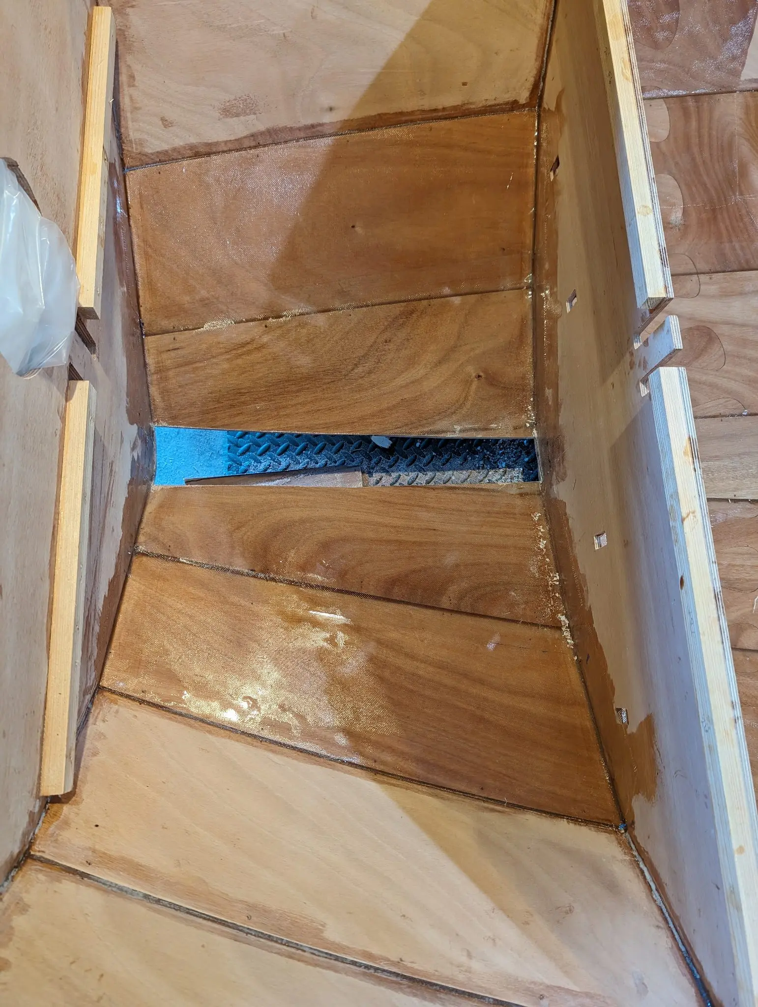
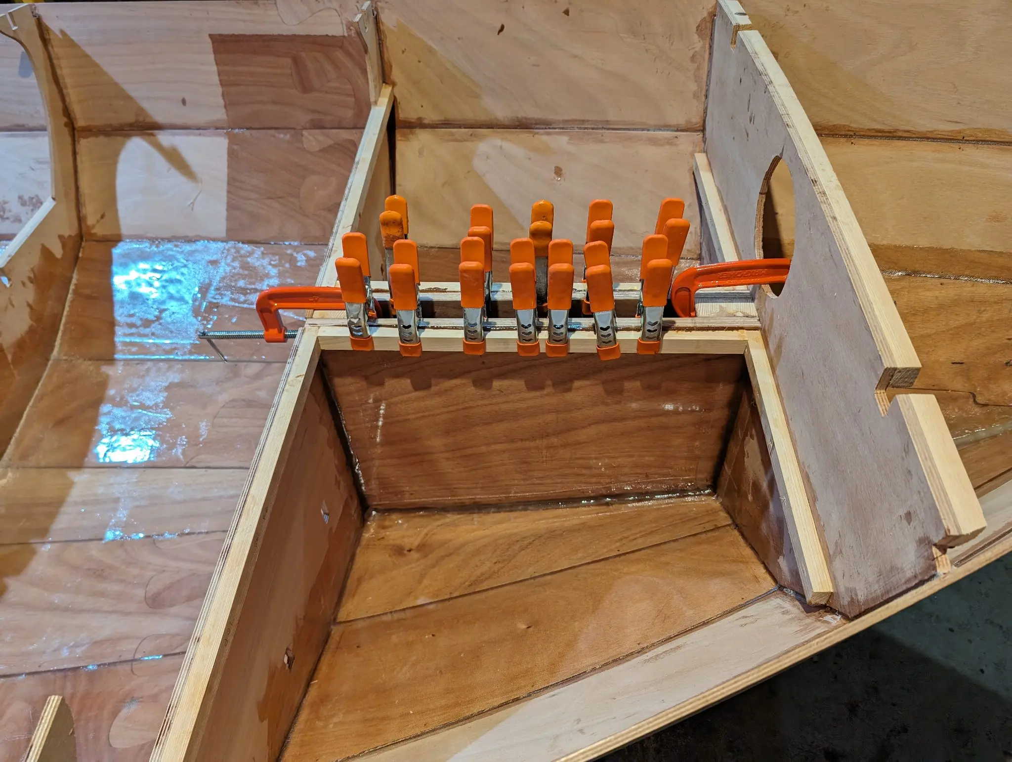
The Guider has its rudder mounted in an inboard cassette. It's a complicated bit of building that is coming up, but here I am building the rudder trunk that the cassette will mount into. The rudder trunk is built much like the centerboard trunk. You use CLC-provided templates to cut out some solid timber edge pieces, then everything is fiberglassed, and the box is glued together. In order to mount the rudder trunk, you have to cut a big slot in the hull for it to sit on. There are alignment slots in the frames and tabs on the trunk to get into the right place. Then the box is filleted and taped in.
Photo 1 Photo 2 Photo 3 Photo 4 Photo 5
27 Apr 2024Stitch & Assembly
Deck cleats and beams installed, dry fitting the deck
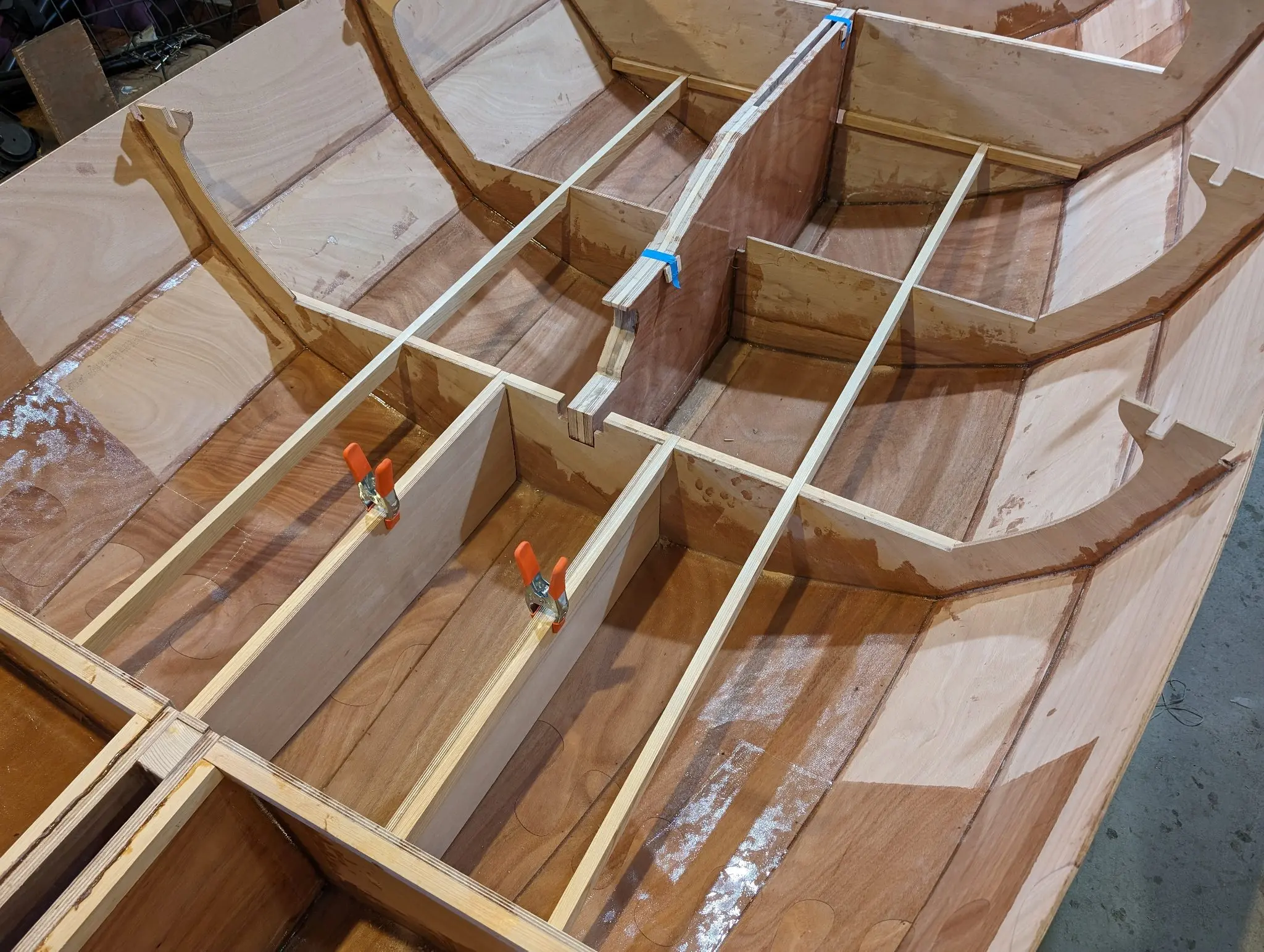
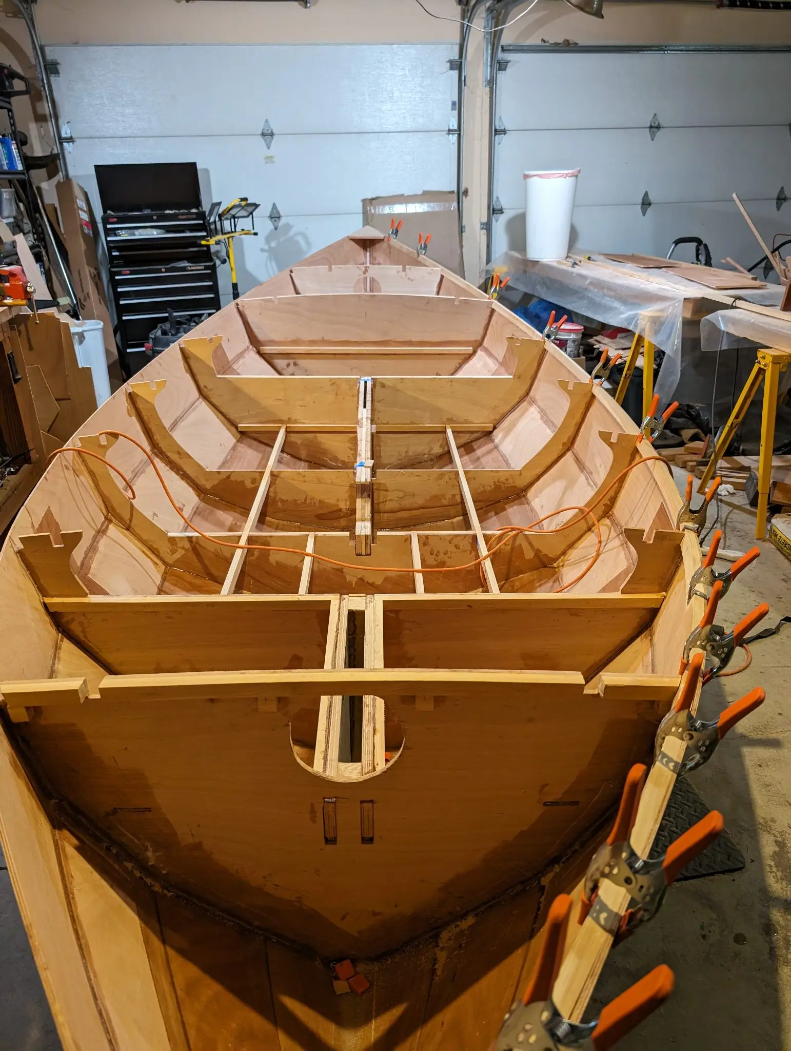
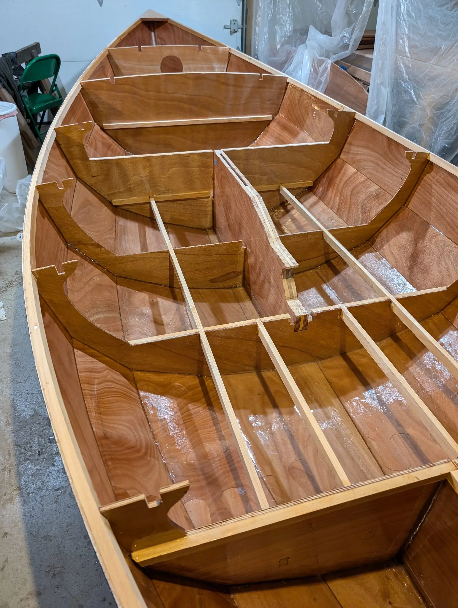
The Guider cockpit is fully enclosed with decks. These decks are supported by cleats on the frames and stiffening beams that run between the frames. Then the decks are dry-fitted to make sure everything is supported. The thin lines on the cockpit decks are the outlines of hatches that will be cout out later.
Photo 1 Photo 2 Photo 3 Photo 4 Photo 5
11 May 2024Stitch & Assembly
Building the rudder cassette (Part 1)
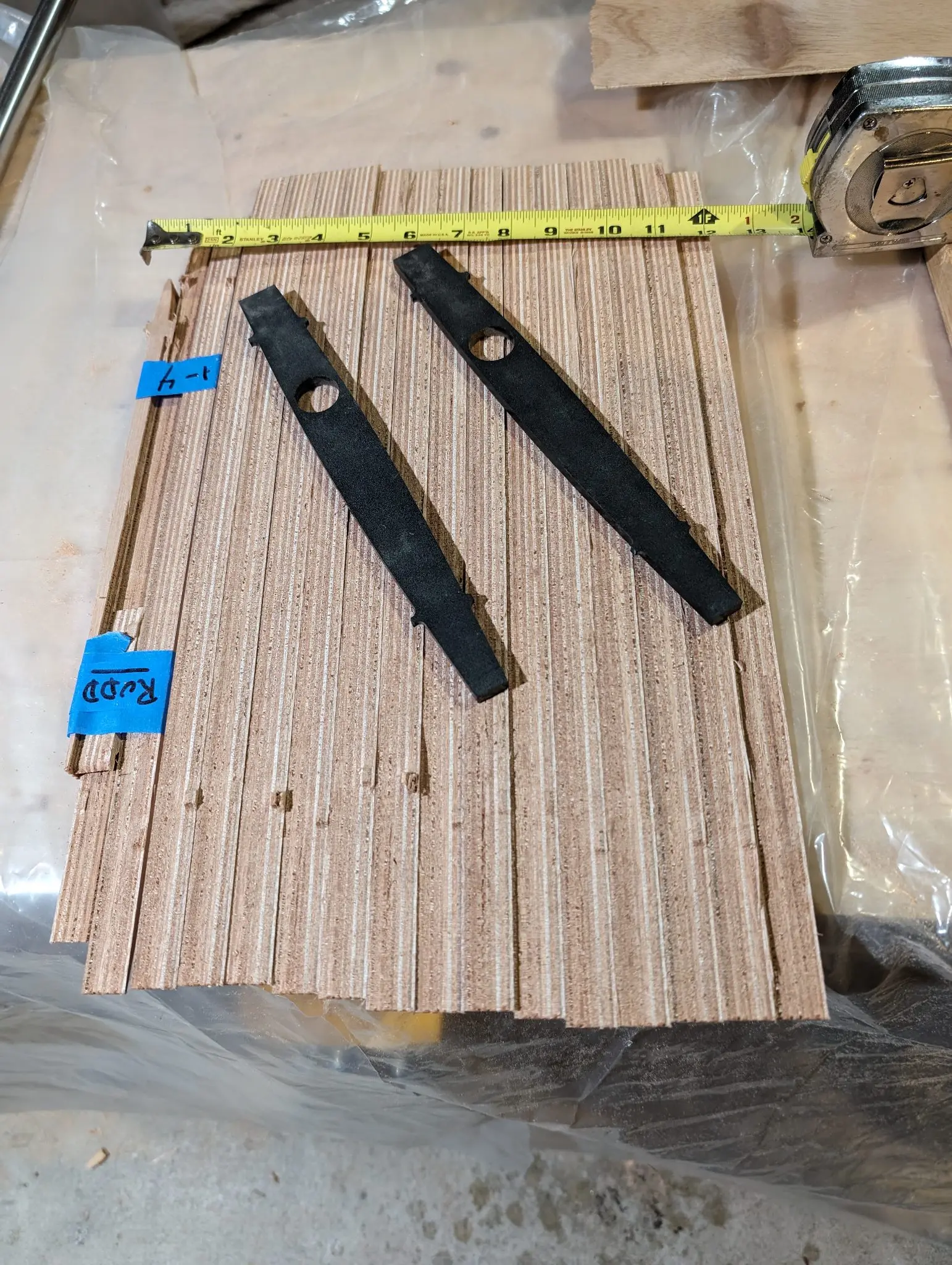
In the Guider the rudder, rudder post and tiller are all mounted in a cassette as a unit that inserts into a rudder trunk at the aft end of the cockpit. The cassette can be raised and pinned so it is fully down for sailing, or halfway pinned to act as a skeg while rowing, or fully raised for beaching the boat. The rudder itself is built up by stacking foil shapes cut from plywood. The stainless steel rudder post extends through the cassette.
Photo 1 Photo 2 Photo 3 Photo 4 Photo 5
19 May 2024Stitch & Assembly
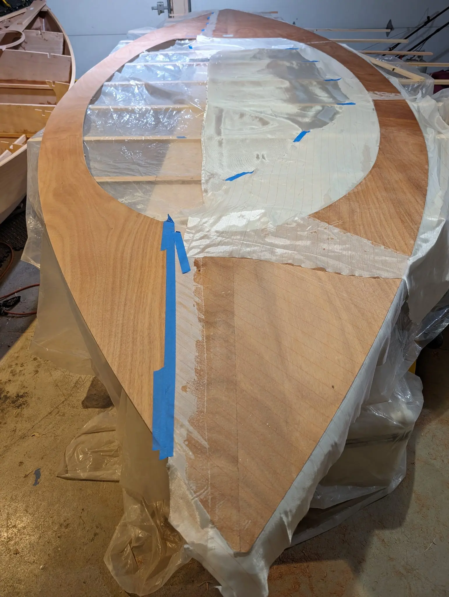
Building the main deck
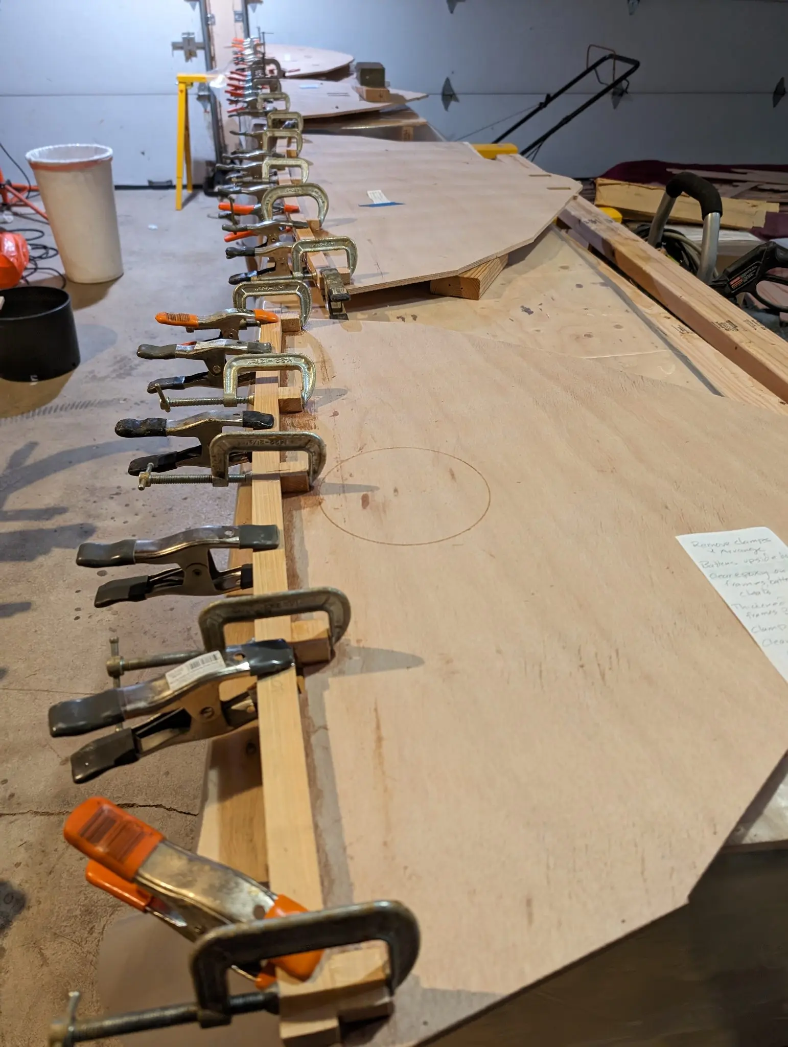
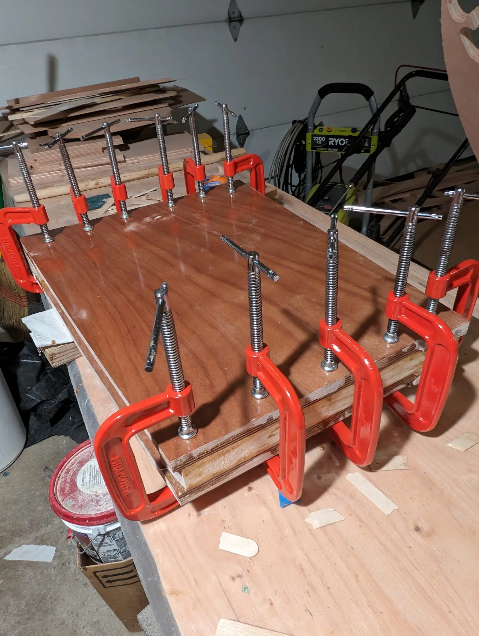
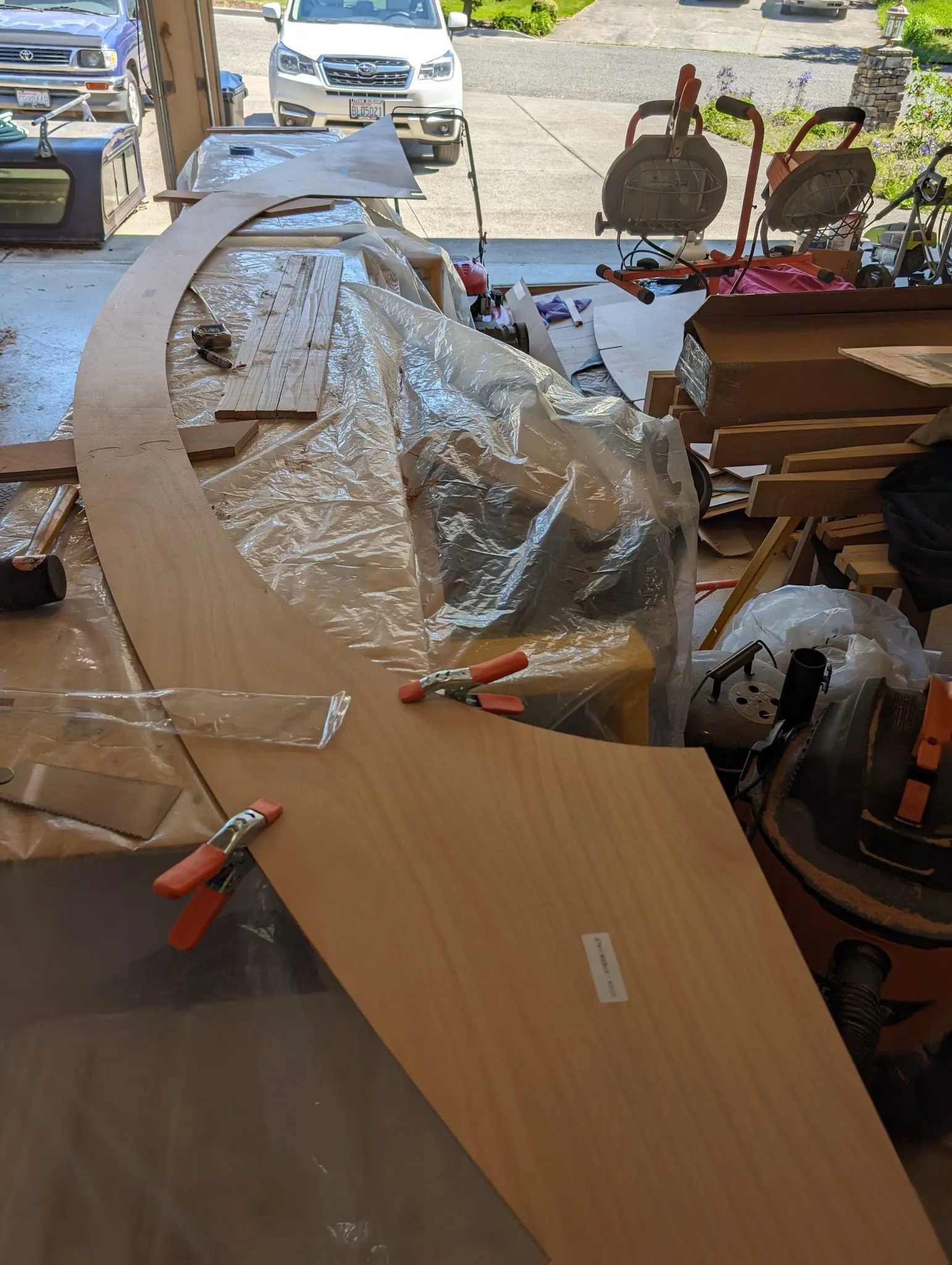
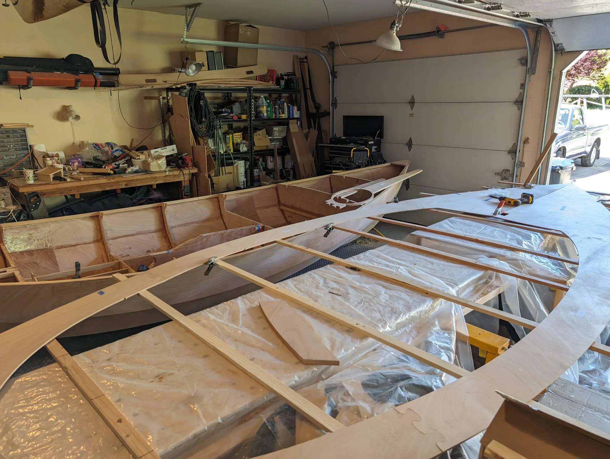
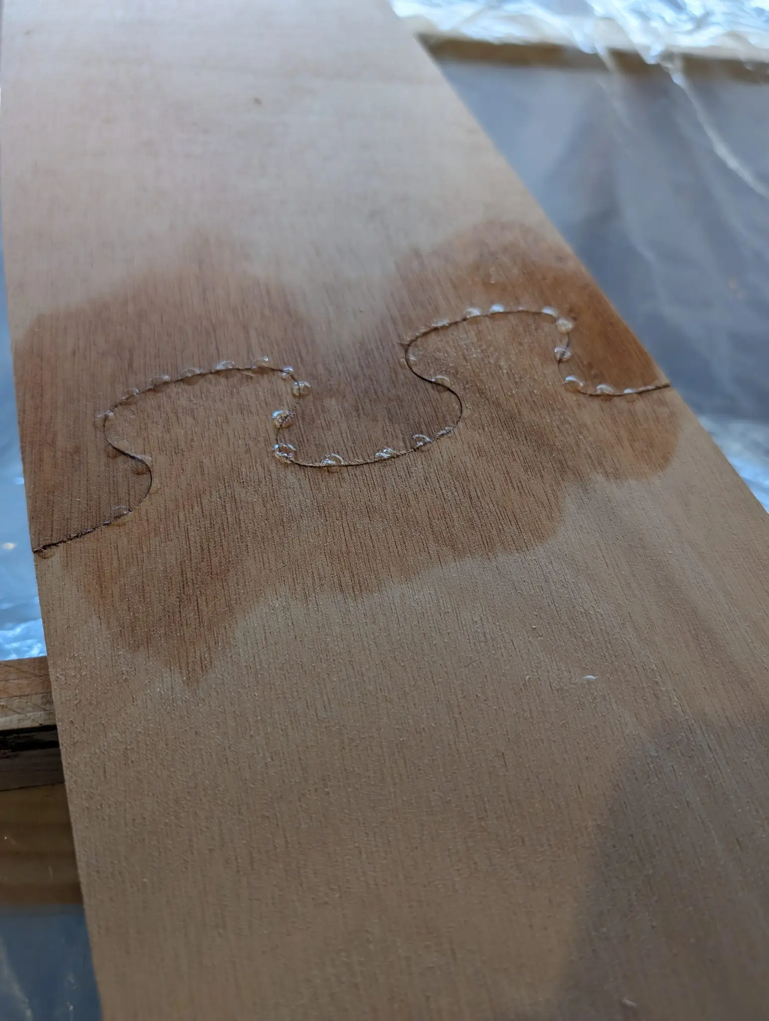
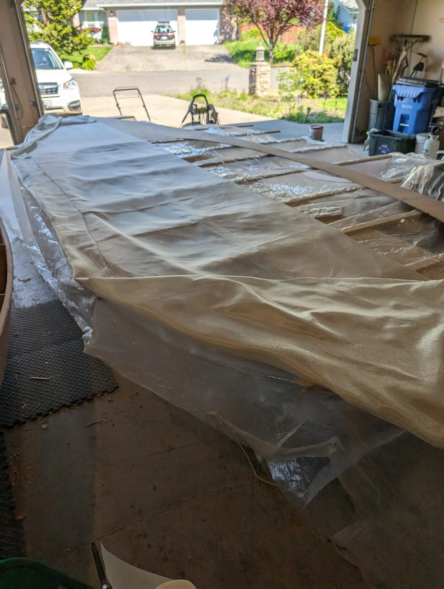
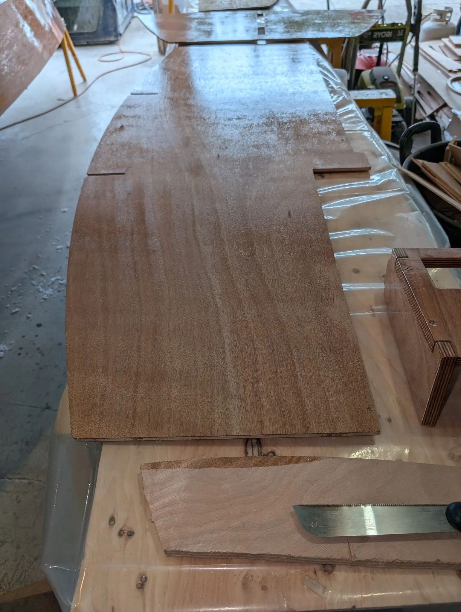
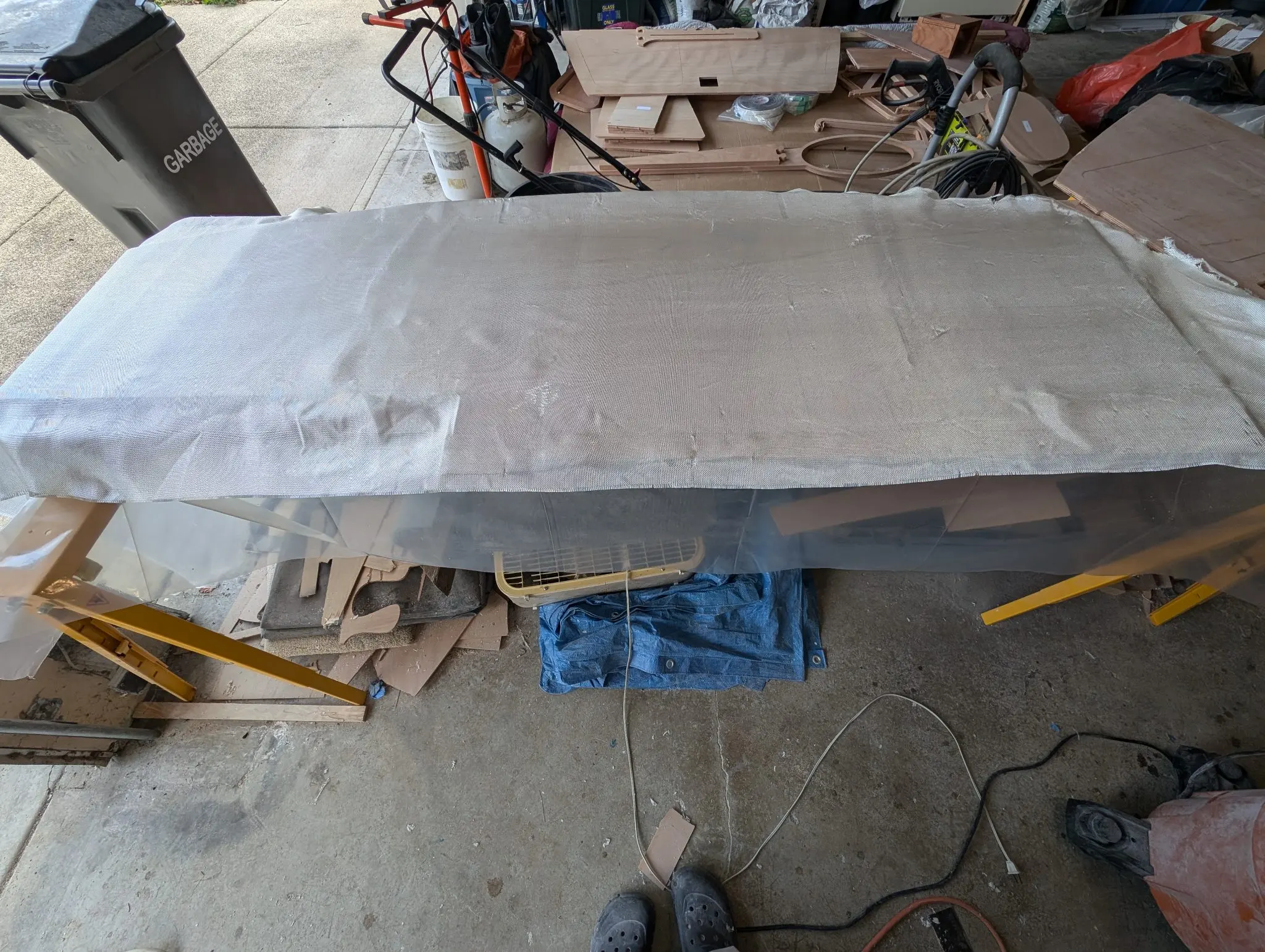
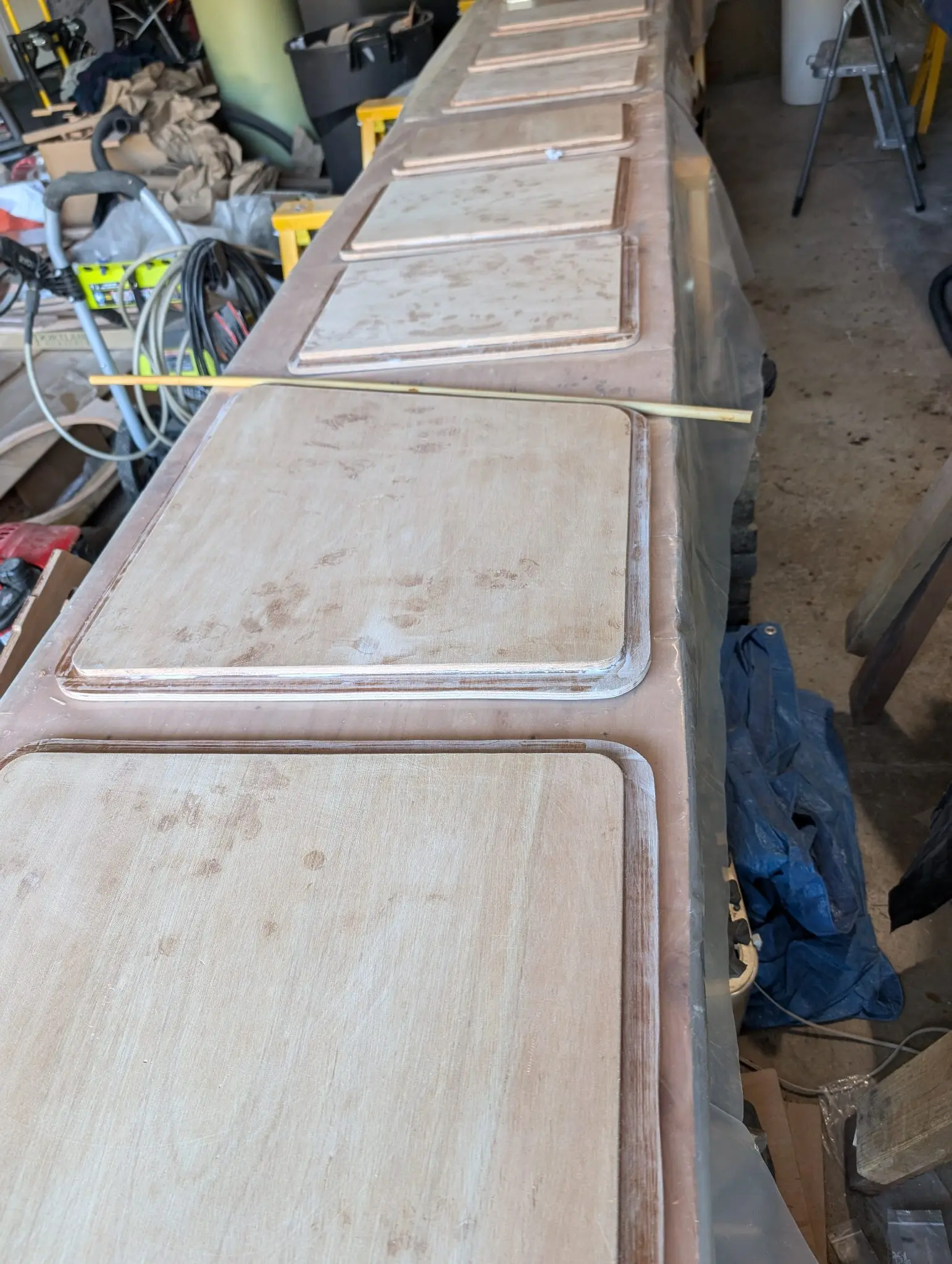
The main deck is built up from three pieces per side, with puzzle joints and epoxy. Then the two sides are mated along the centerline. Finally, both sides are fiberglassed with 3" overlaps in the cloth. I used peel ply fabric on the upper side to get a nice smooth surface. I didn't have a table wide enough to hold the deck piece, so I used firring wood to support it during this process. I u
Photo 1 Photo 2 Photo 3 Photo 4 Photo 5
Chapter 05
Hull Exterior
Turning over, keel and skeg, rubrails, exterior structure.
5 daysfrom May 2024
25 May 2024Hull Exterior
Finishing the rudder trunk
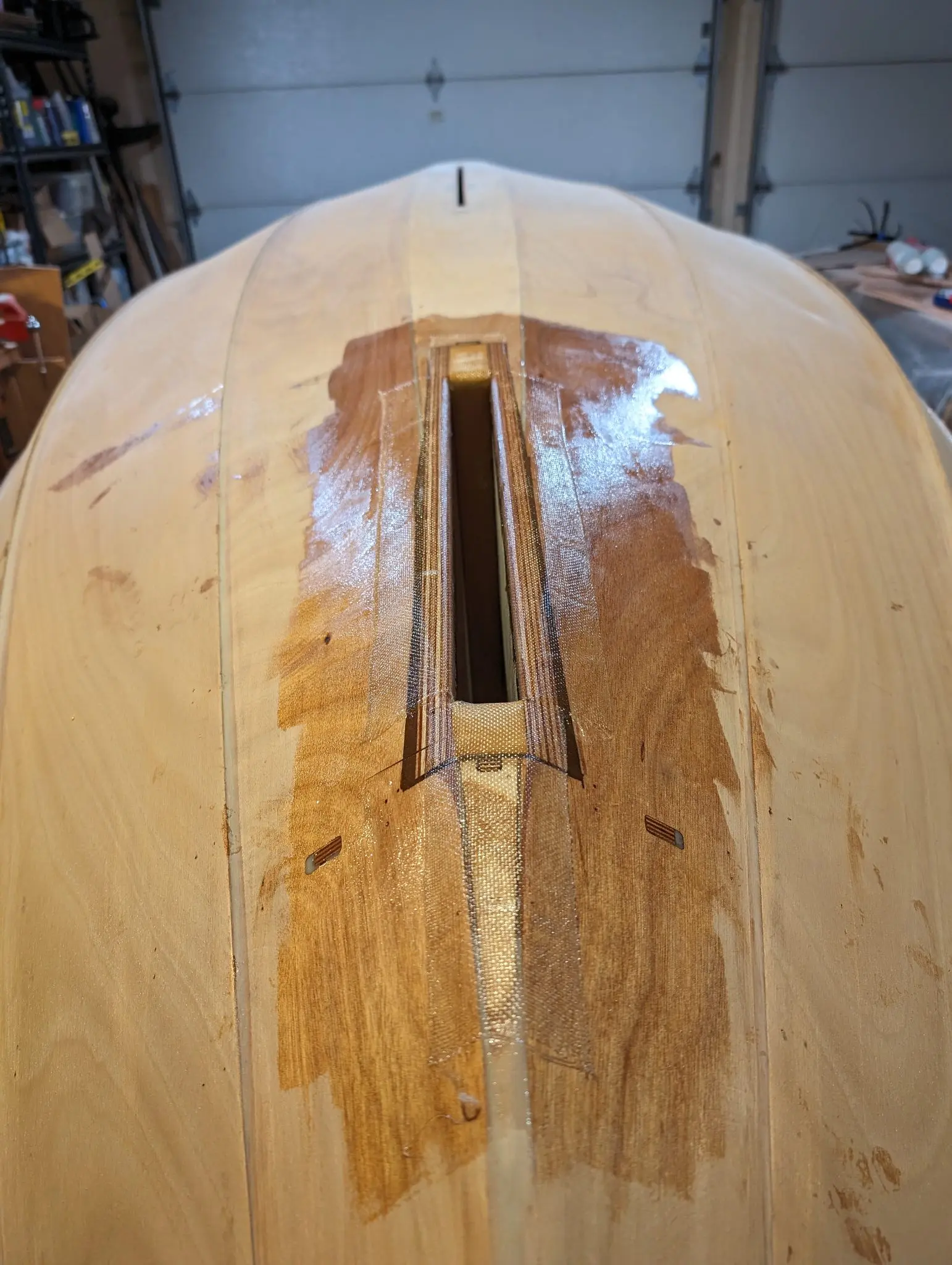
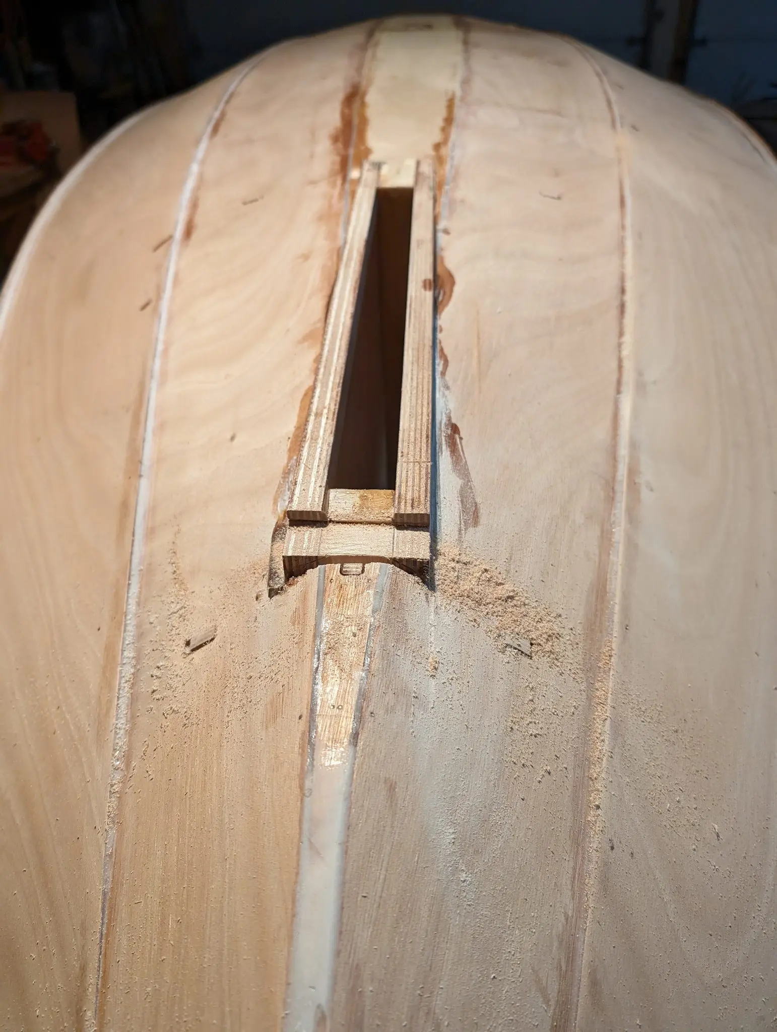
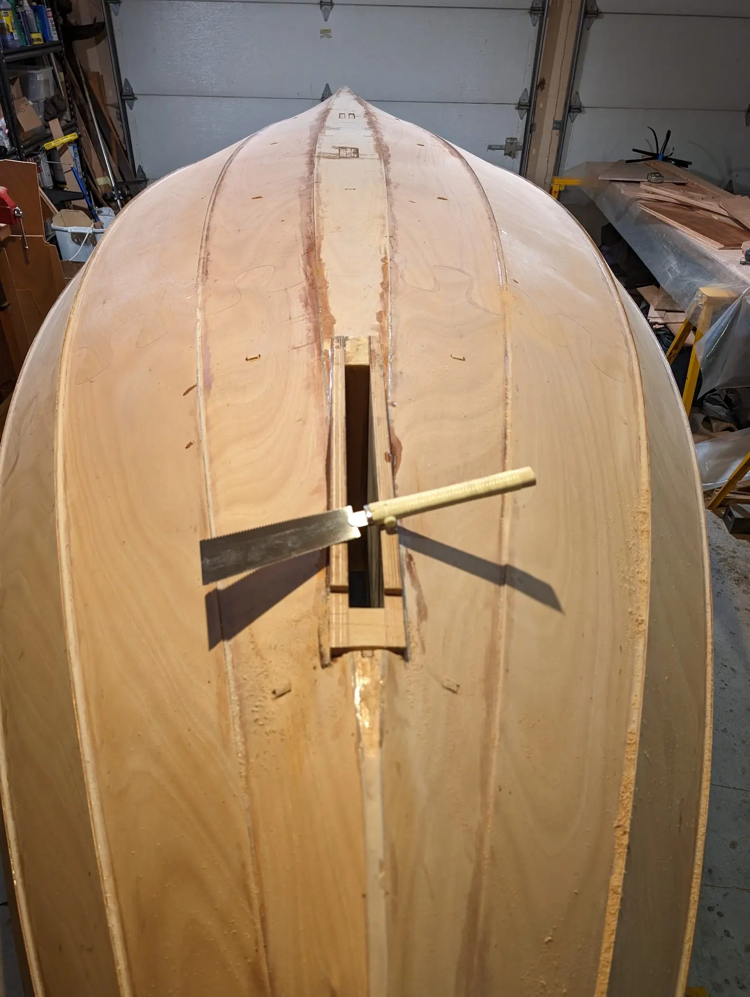
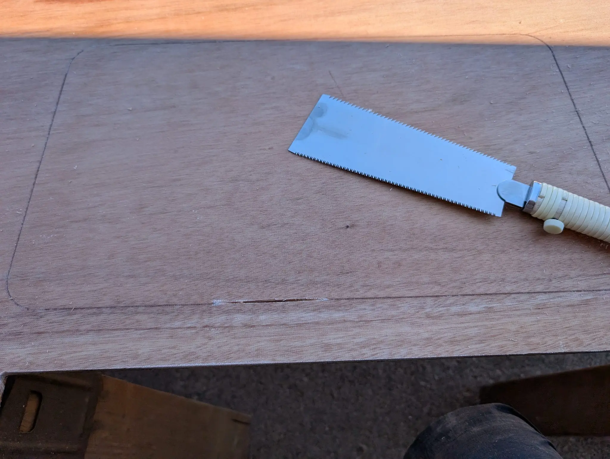
The rudder trunk is inserted through the slot I cut in the hull, as shown in an earlier installment. It aligns by way of notches in the frames. A small amount has to be trimmed off, and the rest is faired into the hull. The primary tool I used for this was a Japanese pull saw. After everything is flush cut and sanded smooth, the joint is reinforced with FG tape.
Photo 1 Photo 2 Photo 3 Photo 4
26 May 2024Hull Exterior
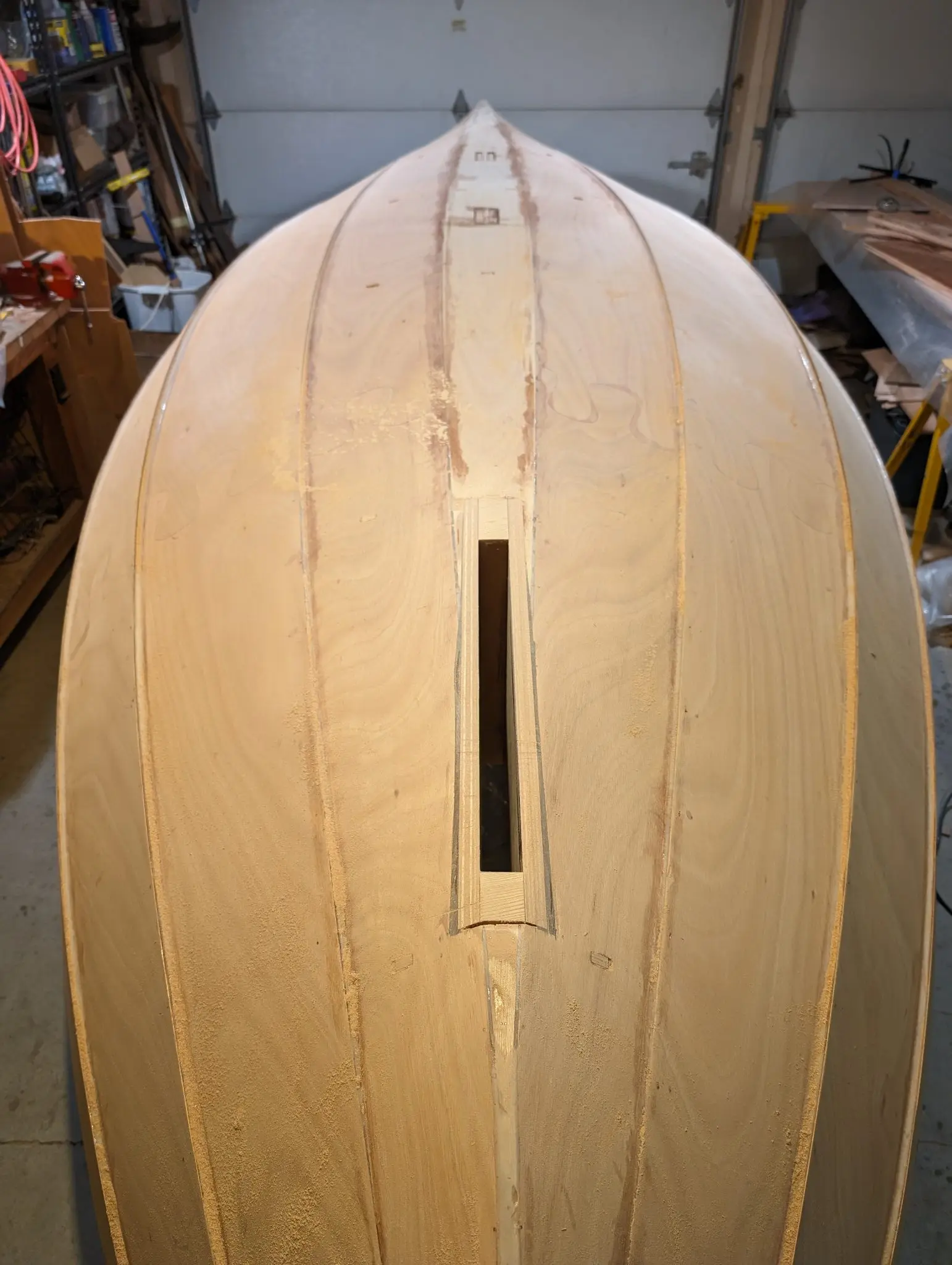
Opening the centerboard slot
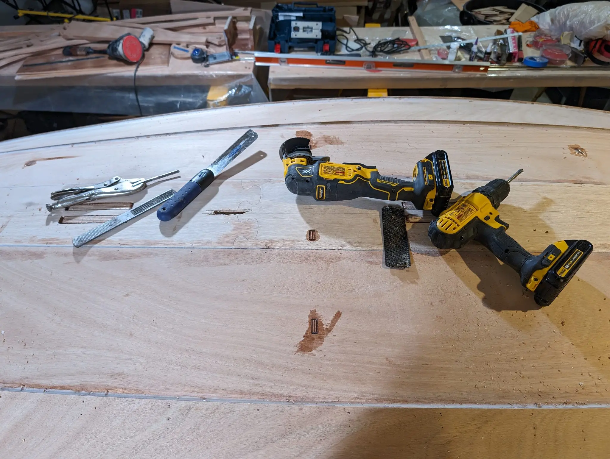
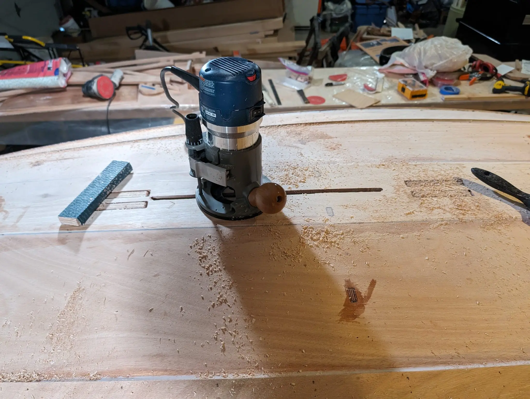
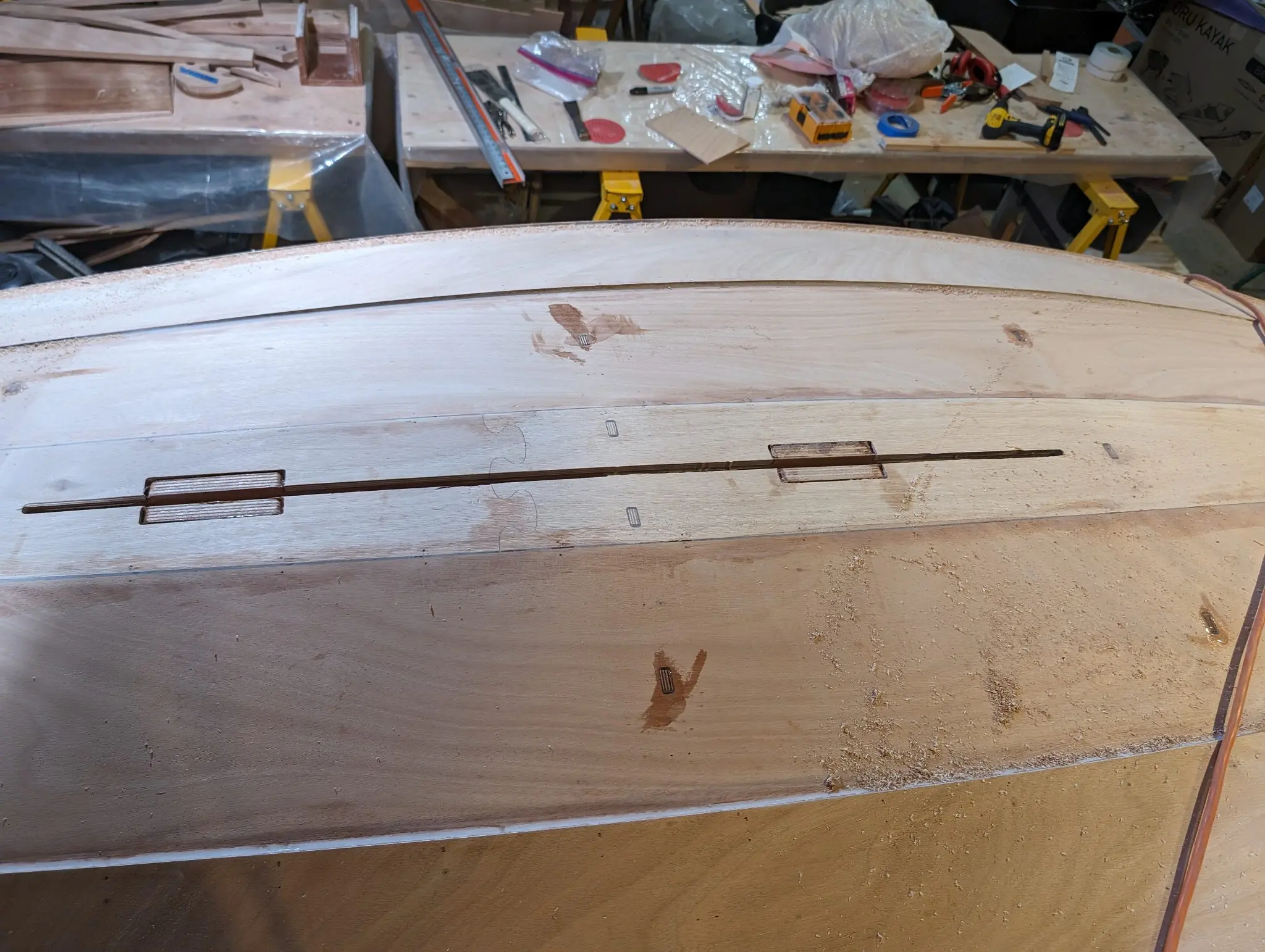
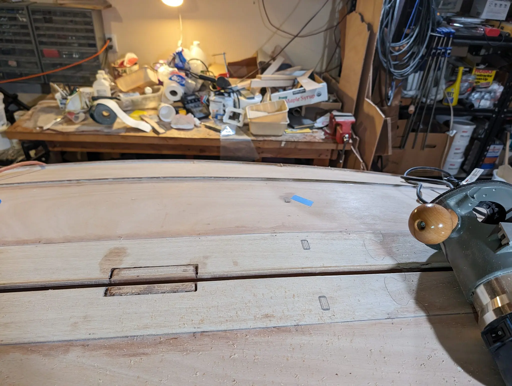
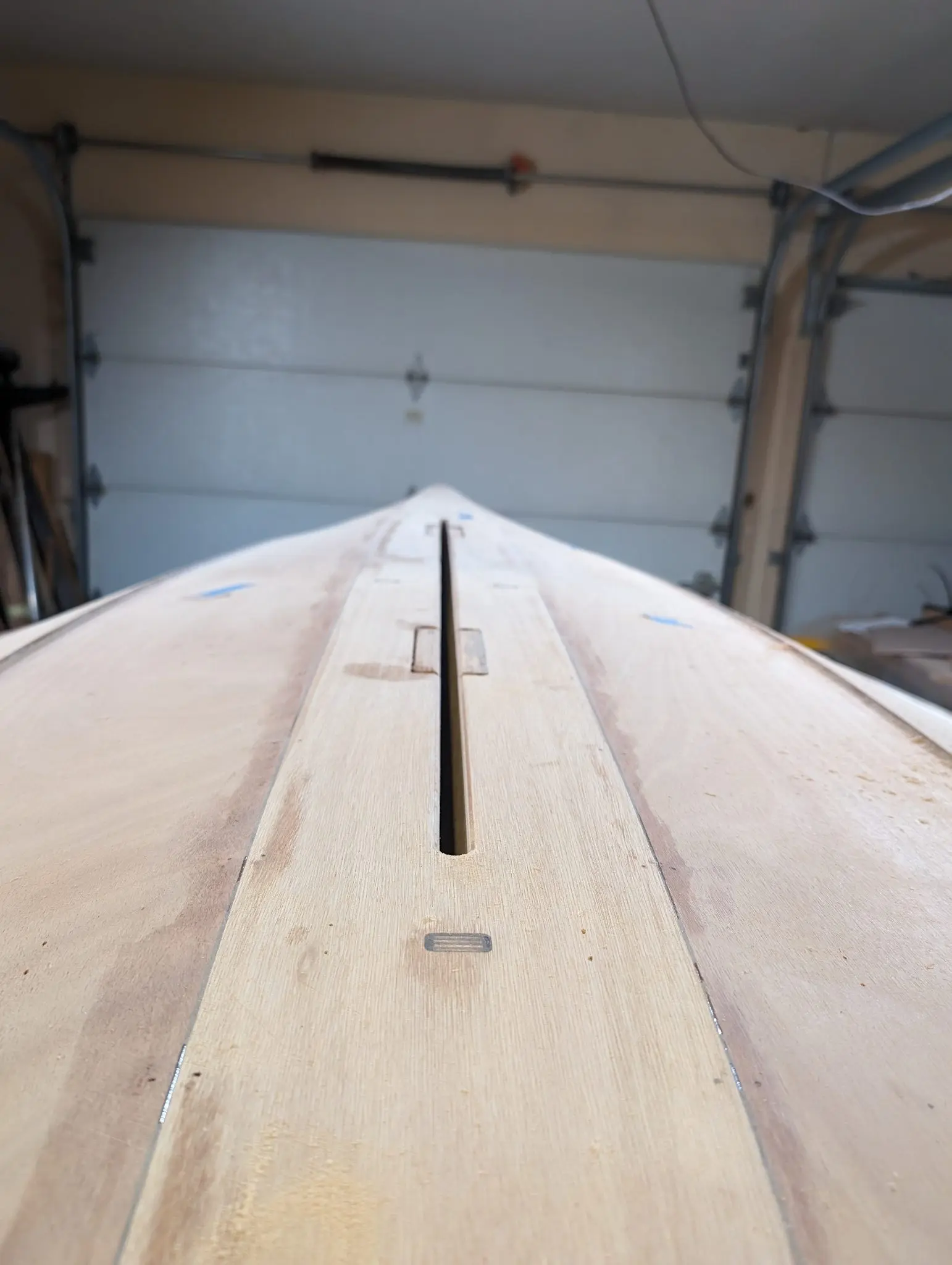
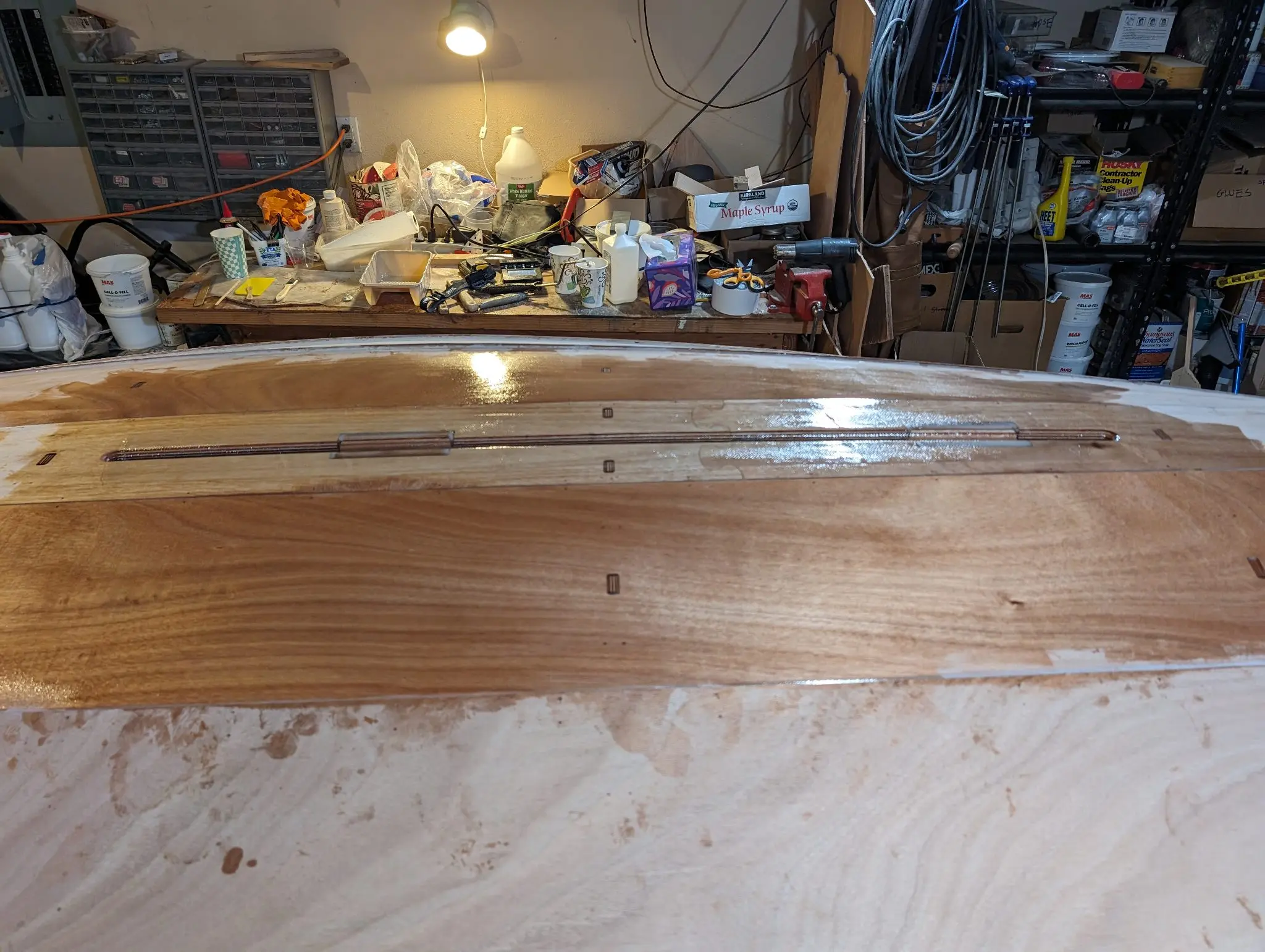
The centerboard trunk is slotted between two frames and is aligned by notches in the hull. To accommodate the passage of the centerboard, a slot has to be cut in the hull between the two inner walls of the centerboard trunk. I tried a variety of tools to do this, but finally realized the ideal tool for the job was a flush trim bit on my router. I chased this up with a roundover bit and then the joint between trunk and hull was reinforced with FG tape.
Photo 1 Photo 2 Photo 3 Photo 4 Photo 5 Photo 6
Chapter 06
Glassing & Epoxy
Sheathing in cloth, wetting out, fill coats.
1 dayfrom August 2024
23 Aug 2024Glassing & Epoxy
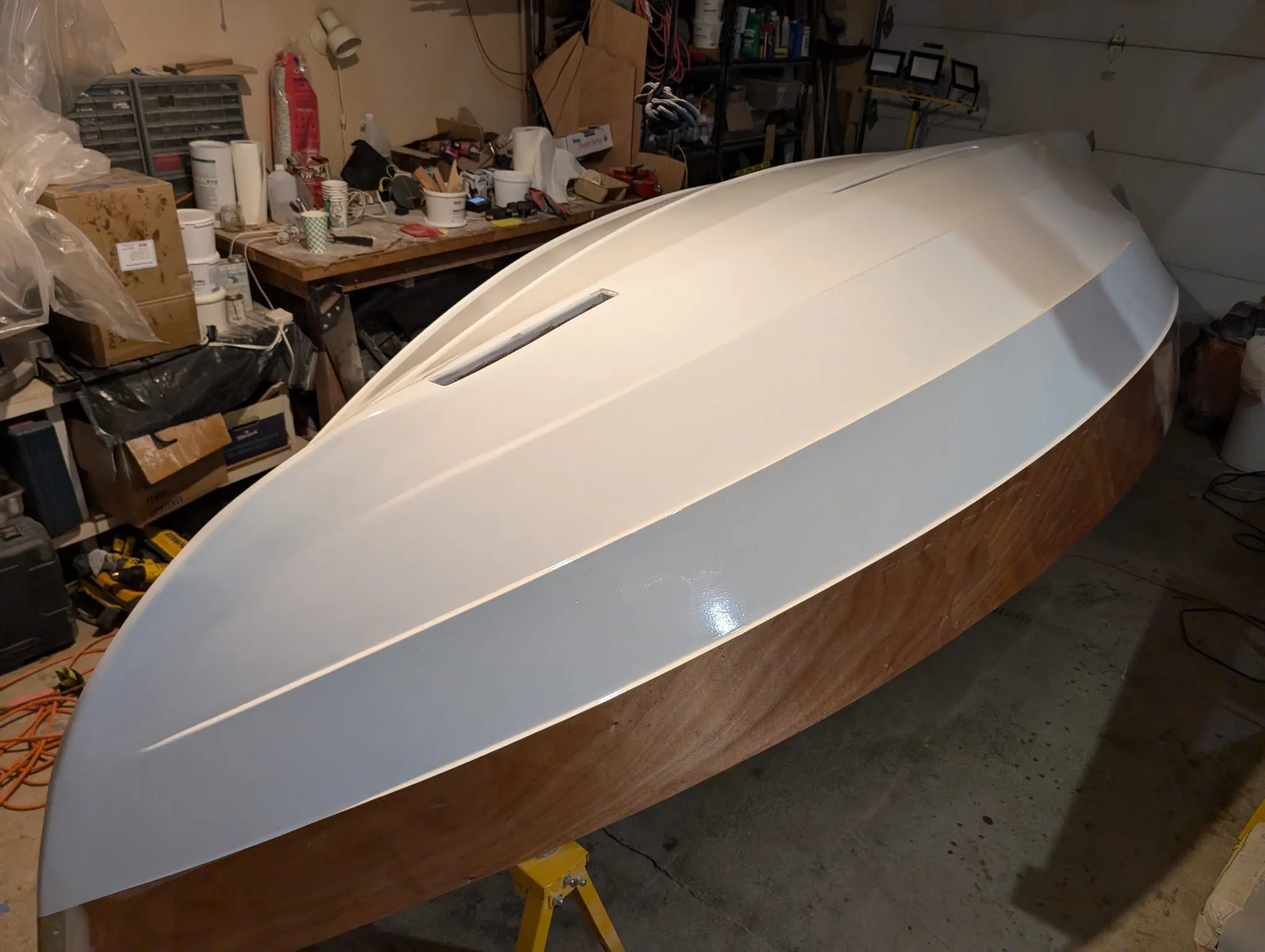
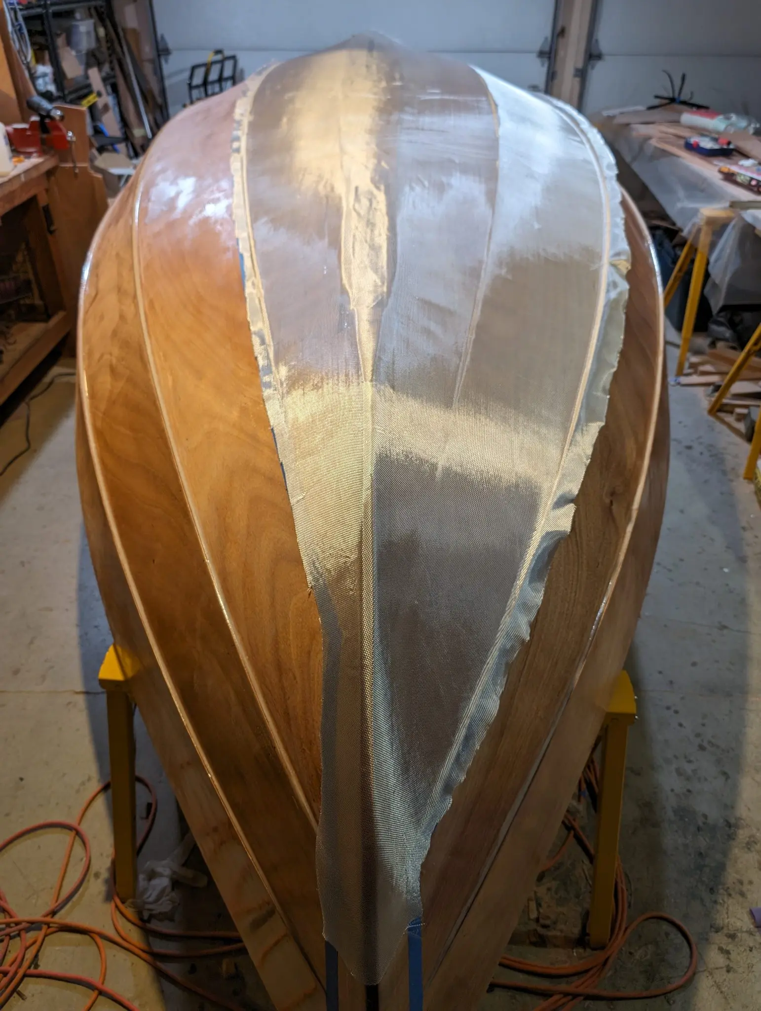
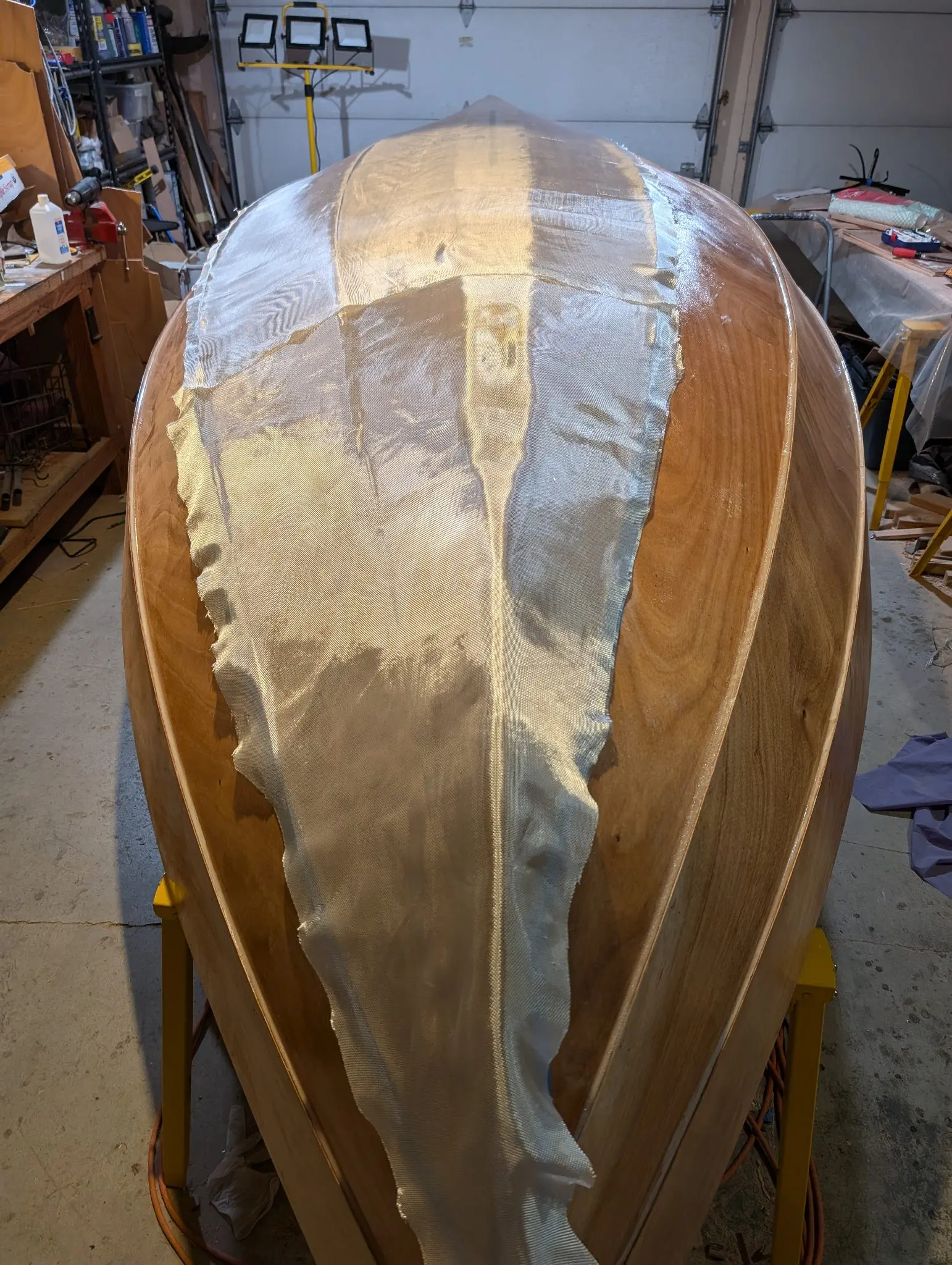
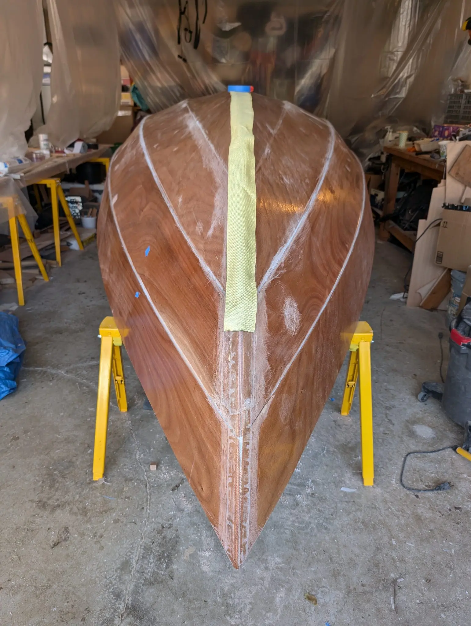
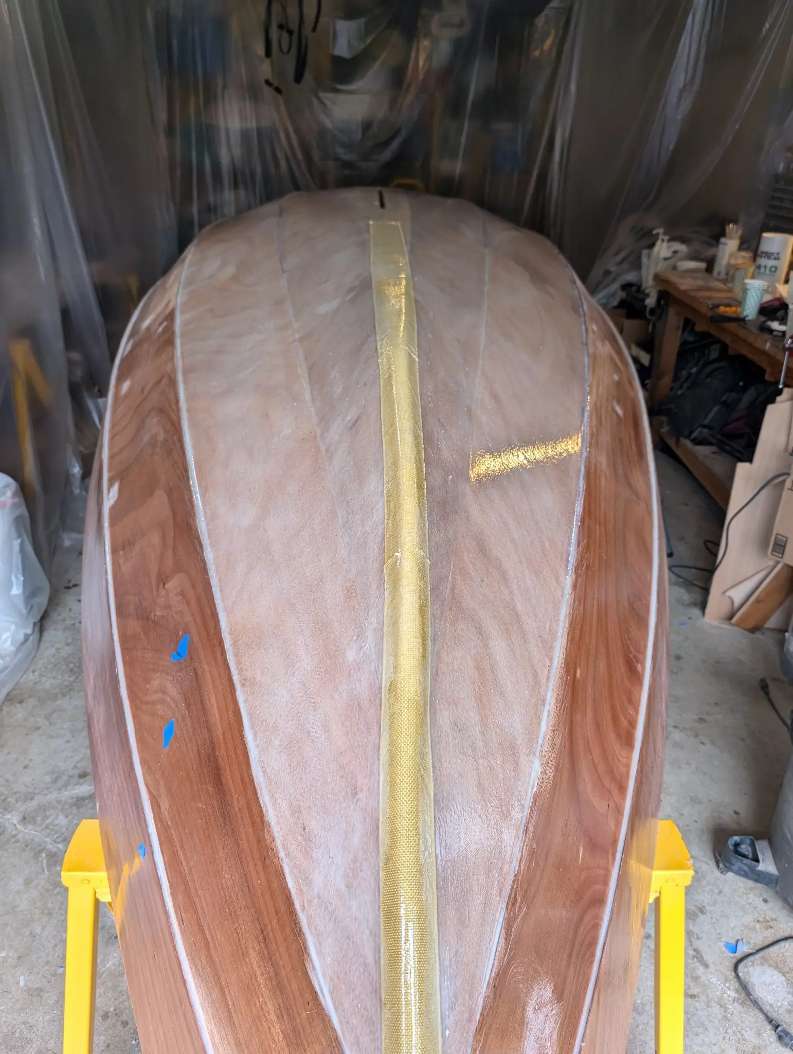
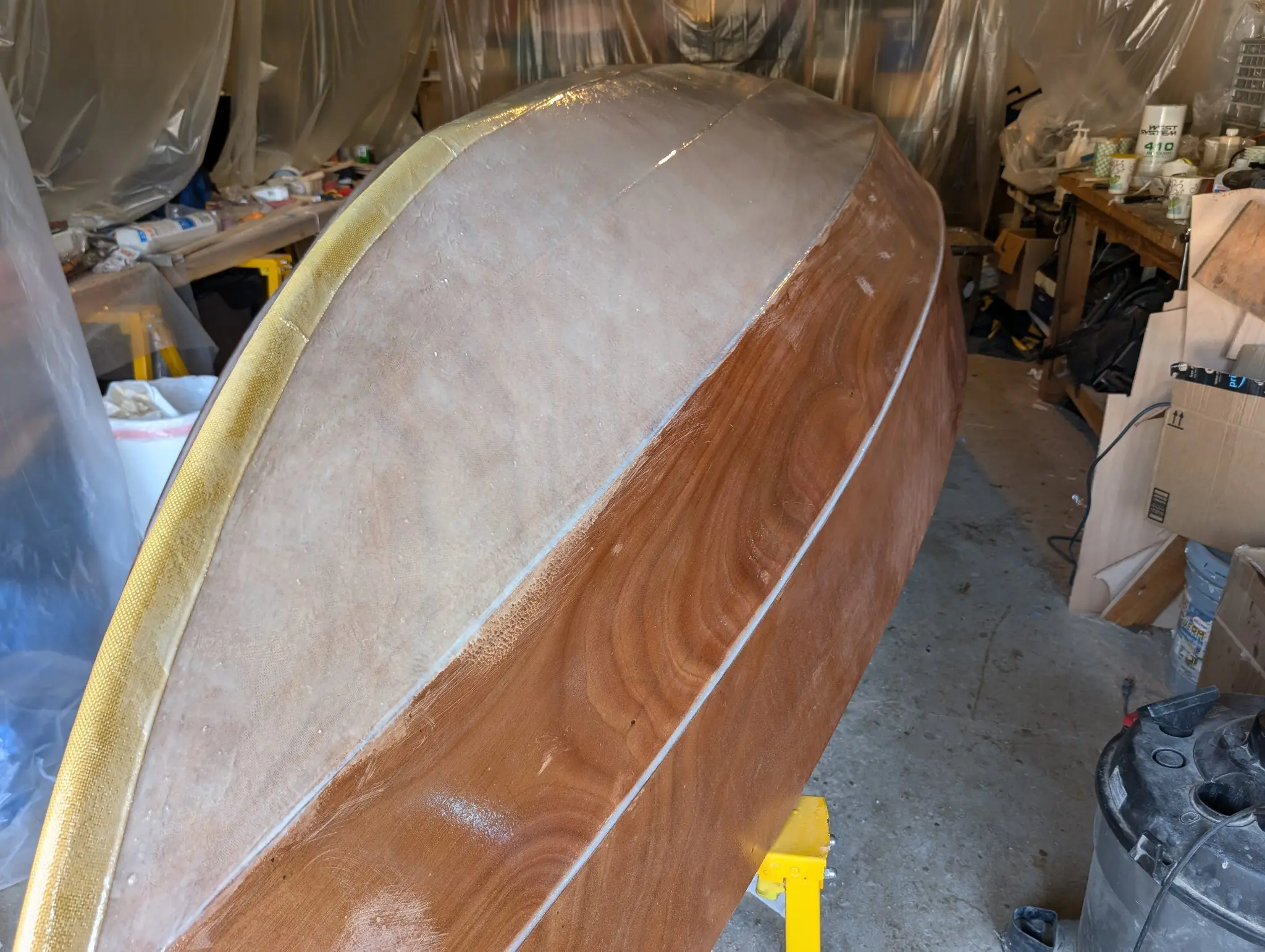
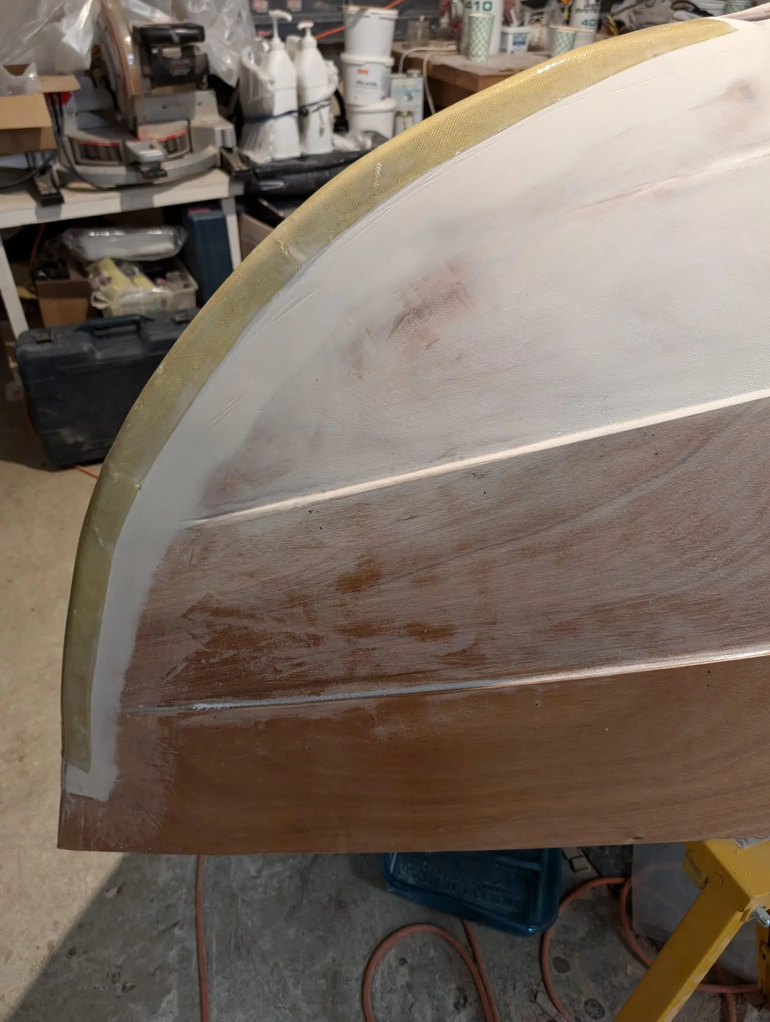
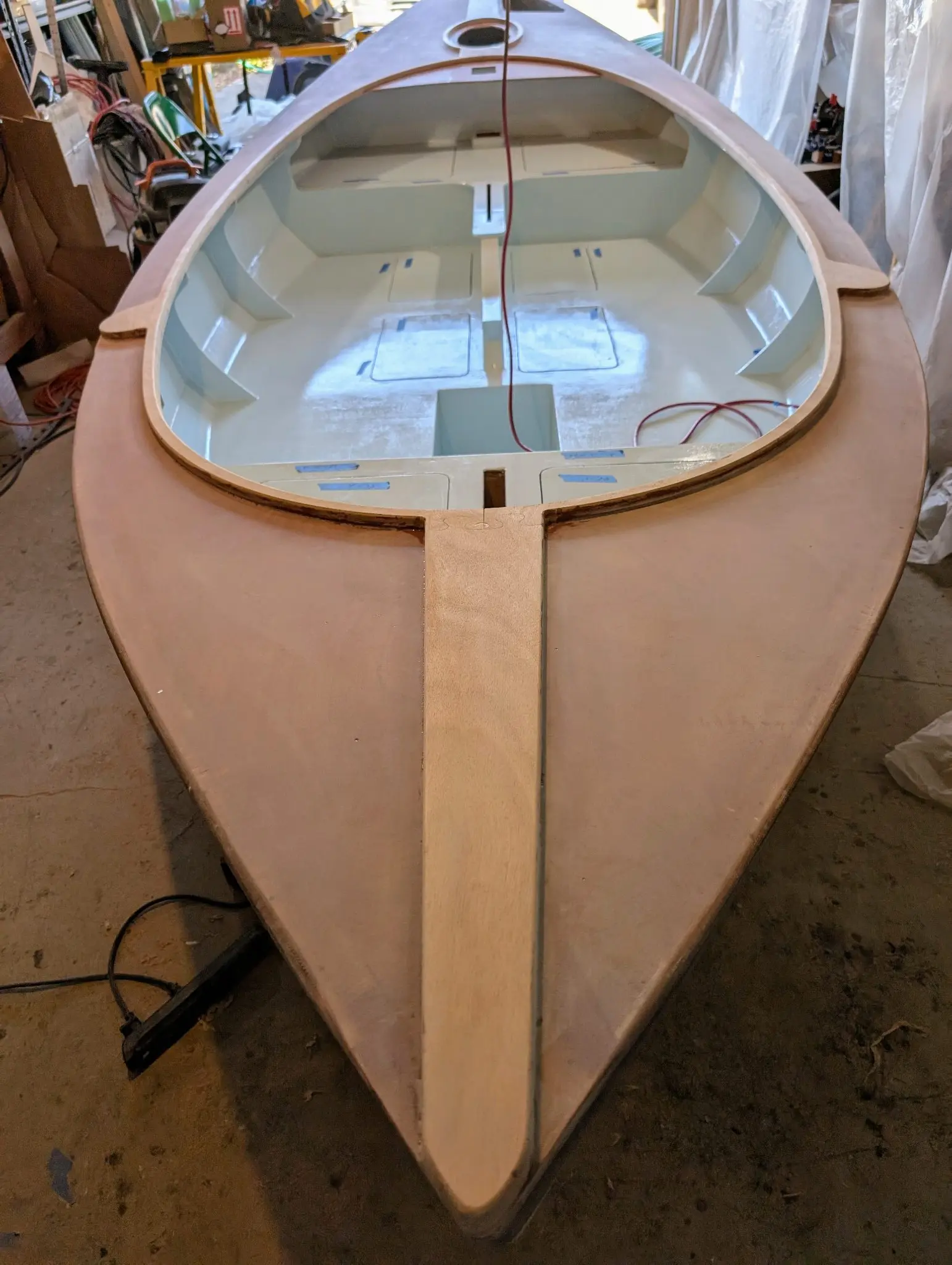
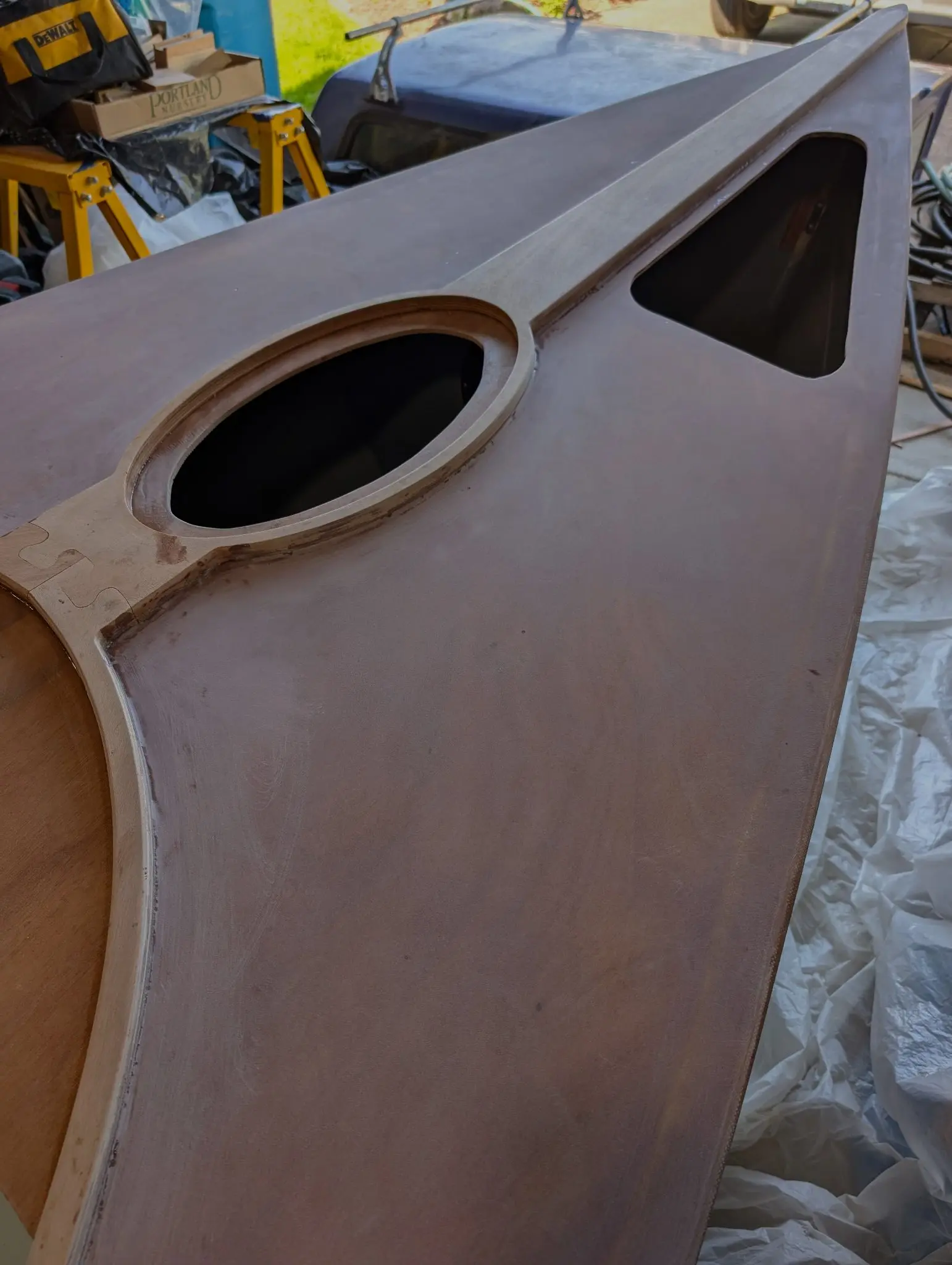
What followed was a lengthy process of saturating, fiberglassing, fairing, sanding the hull (so MUCH sanding, so MUCH DUST). Everything on this boat will be painted because I loathe varnishing. The only thing I did differently from the CLC instructions was to put lengths of Kevlar tape at the bow and stern for increased abrasion resistance. This process required about 6 weeks of work (June 15th - Aug 23rd).
Epoxy the cockpit decks, cutting hatches, installing hatch gutters
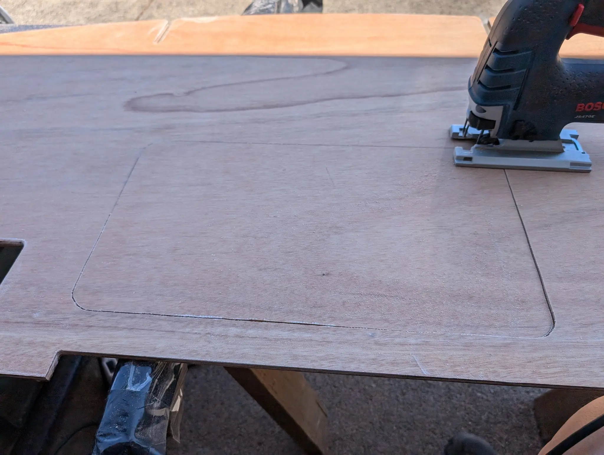
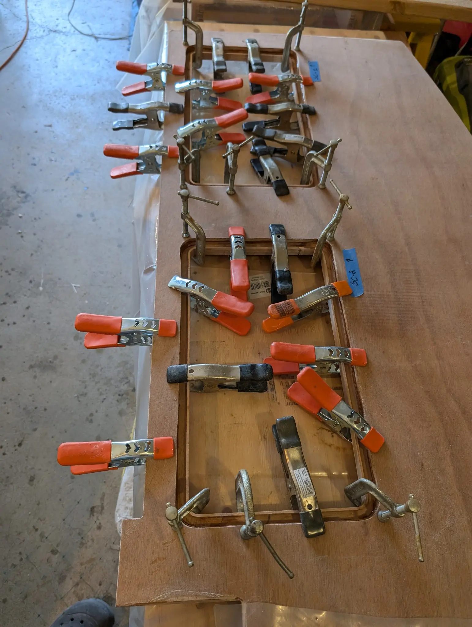
Every deck is fiberglassed on both sides. There are 10 deck hatches on the Guider. Each one is scribed by CNC and must be cut out by the builder. I tried several methods of doing this, but I just came back to using a saber/jig saw, as everyone else does. Cutting the corners of the hatch cutouts is challenging, and I did not cover myself in glory here, but I got it done. Every hatch opening then has a hatch gutter epoxied to its underside. A gasket (weather strip) is installed on the underside of the hatch itself to make it all more or less watertight. The forward cockpit deck has an additional beam on its underside to reinforce it.
Photo 1 Photo 2 Photo 3 Photo 4 Photo 5 Photo 6
Chapter 08
Paint & Finish
Primer, topcoat, bottom paint, boot stripe, lettering.
3 daysfrom September 2024
10 Sep 2024Paint & Finish
Painting the hull
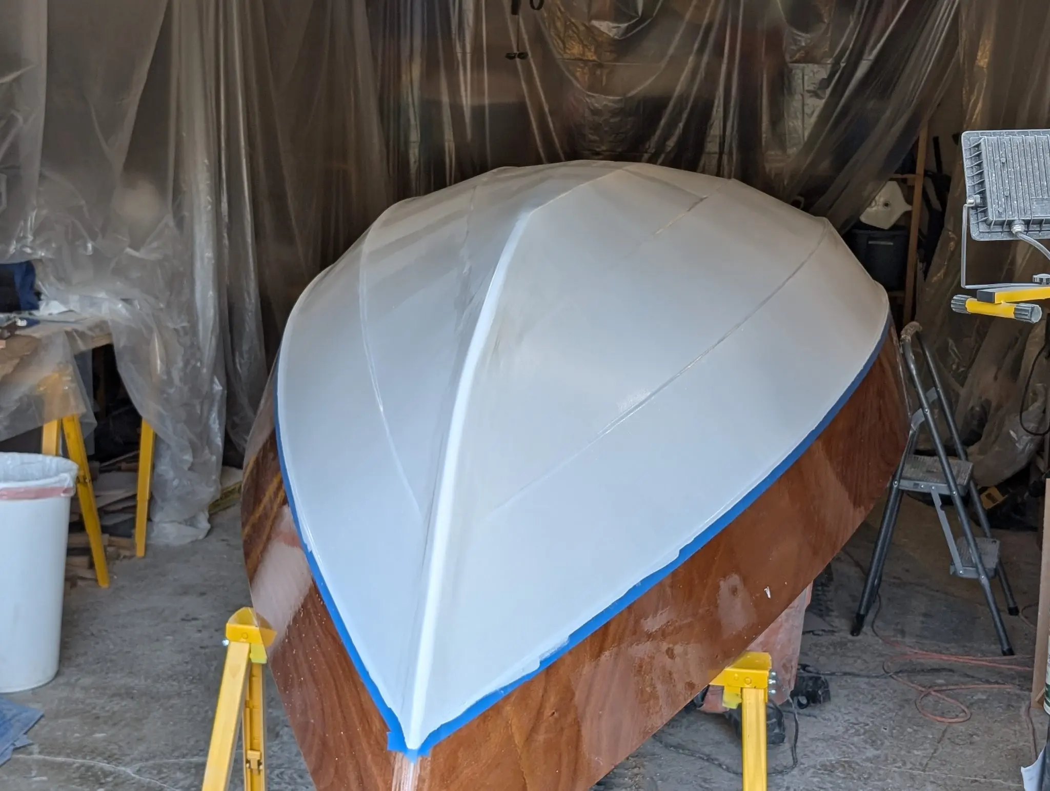
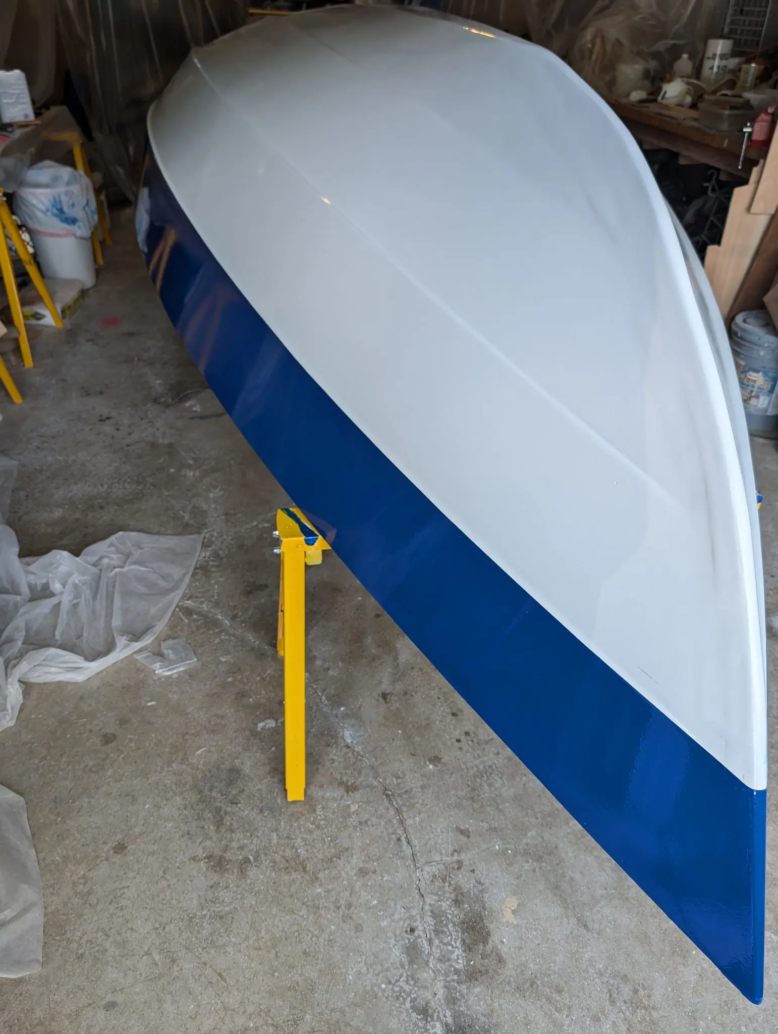
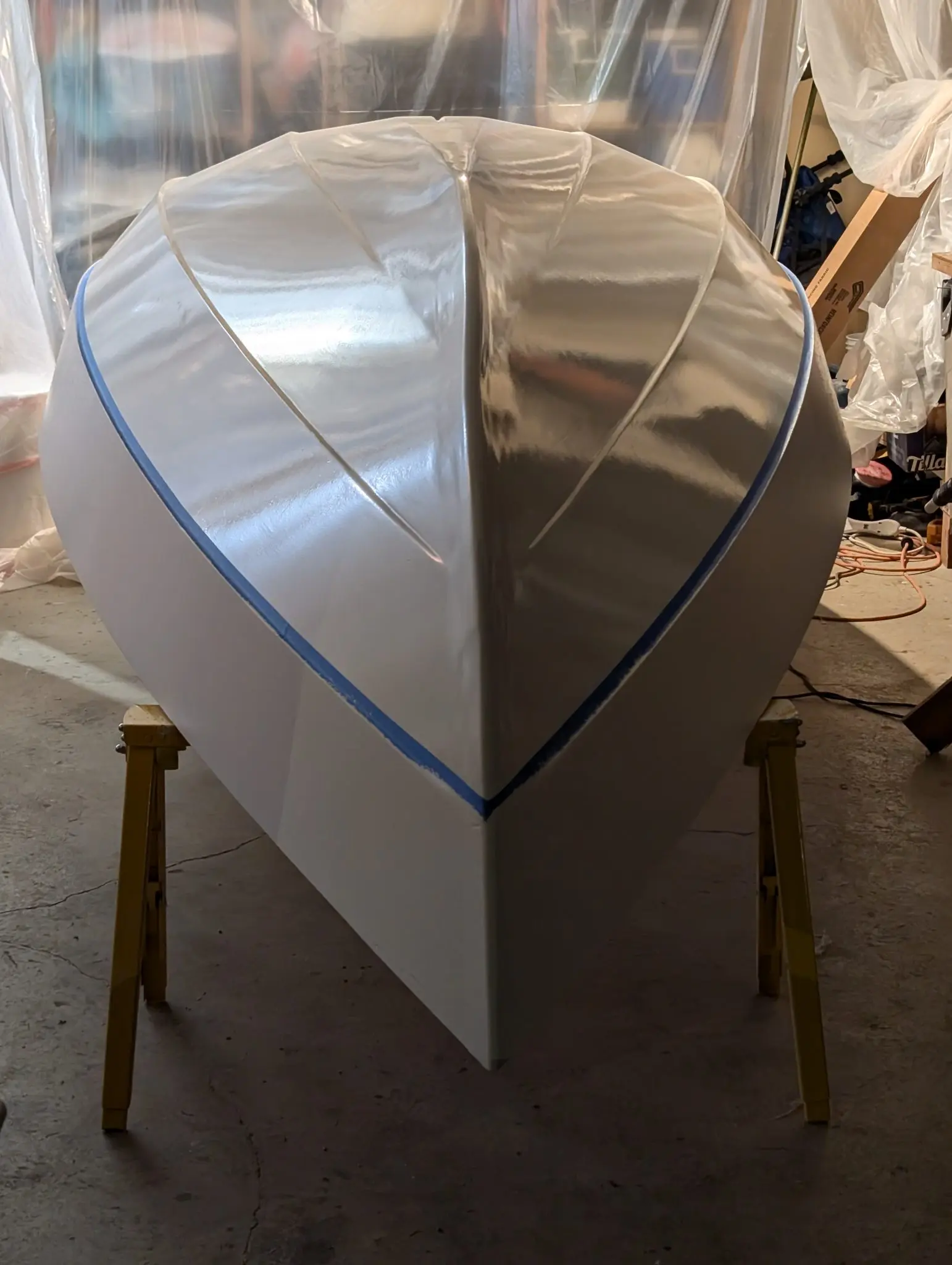
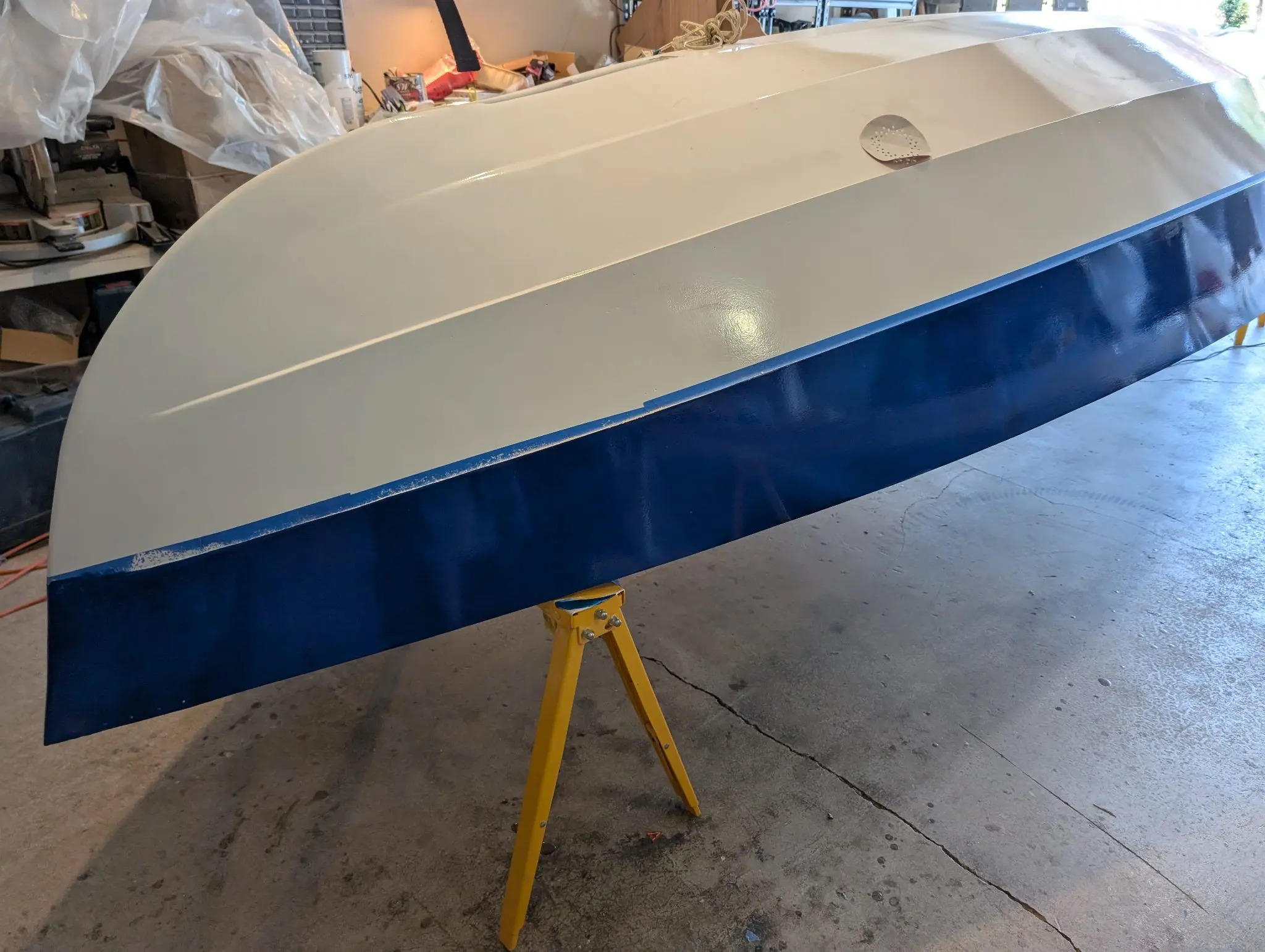
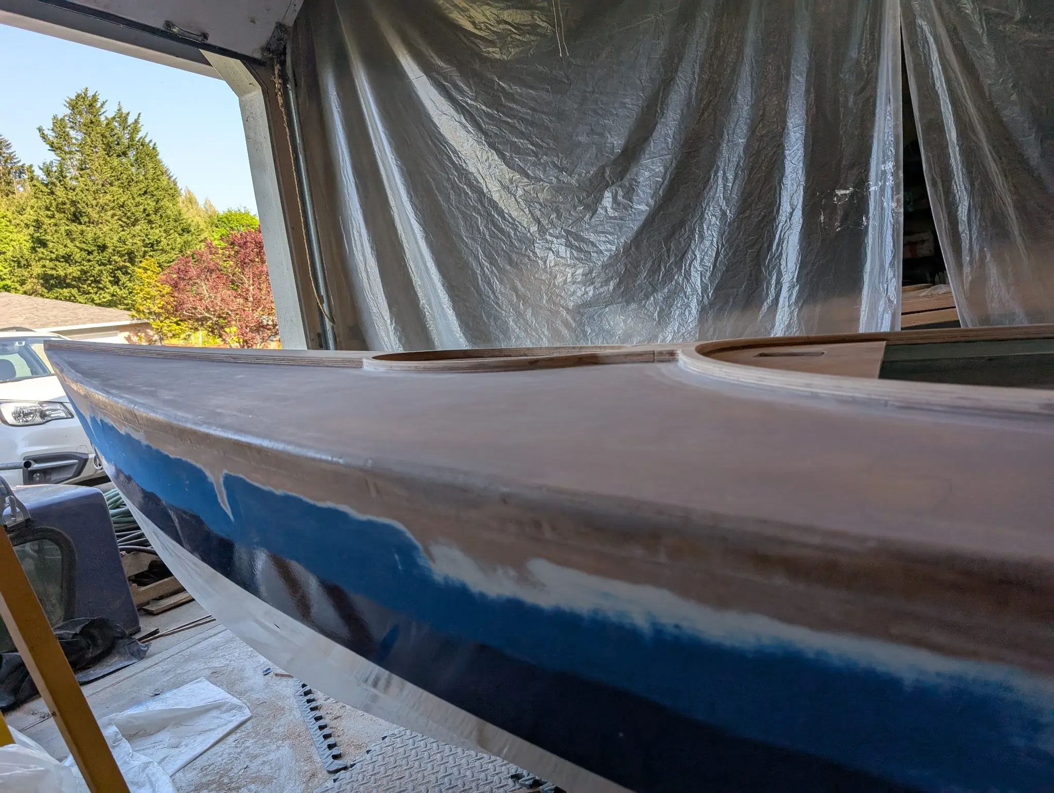
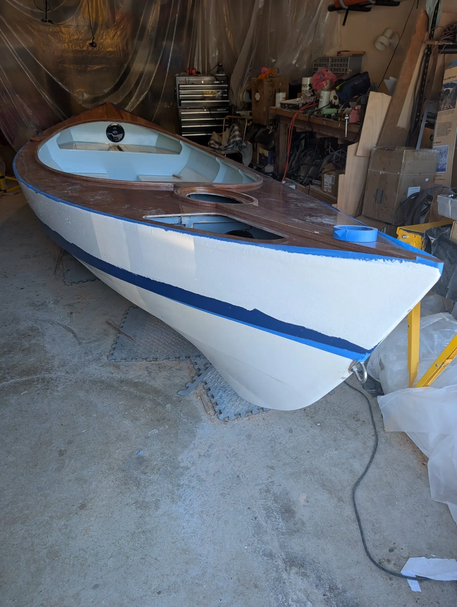
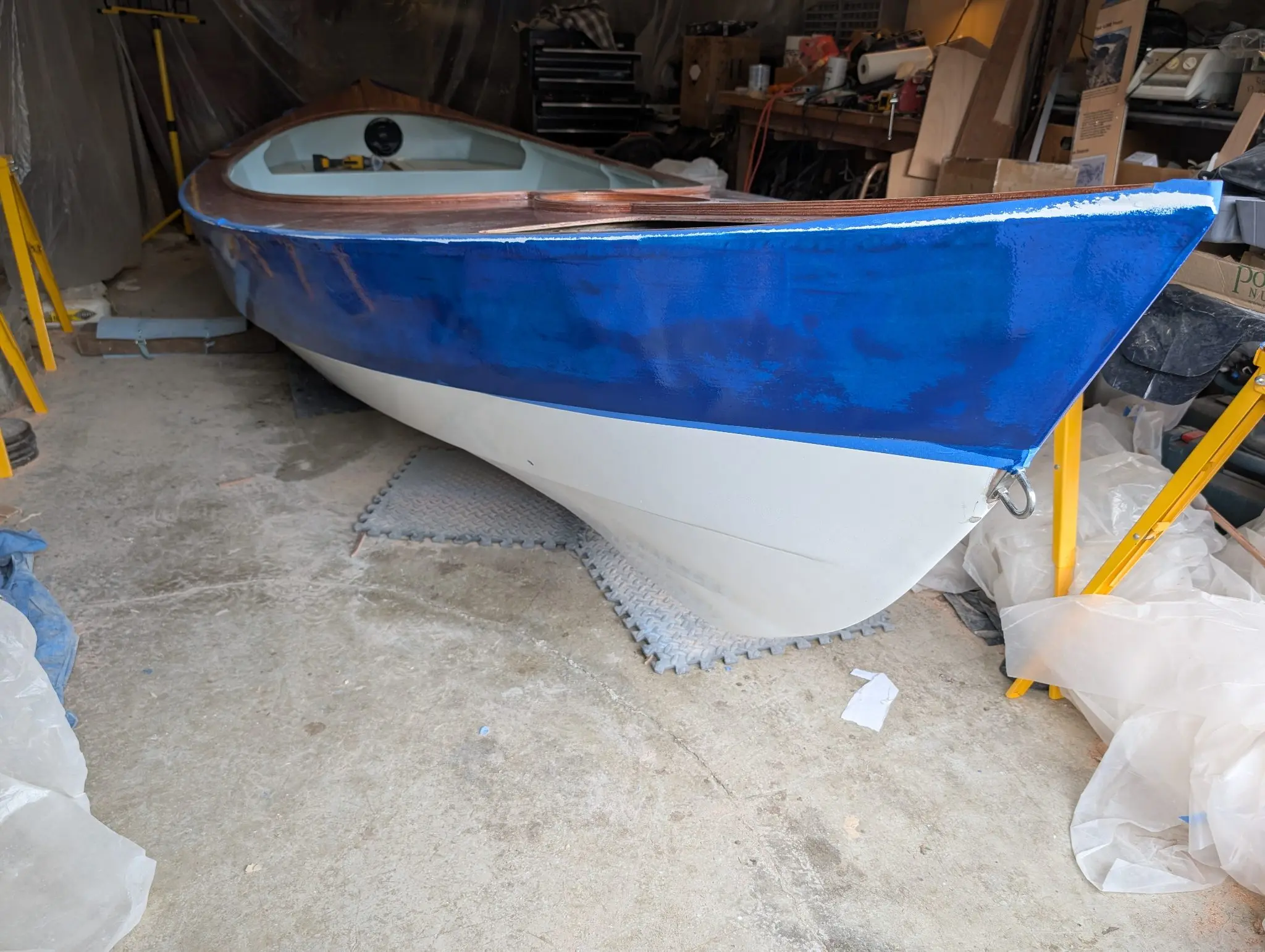
Initial paint on hull exterior. I briefly considered leaving the #4 strake finished bright. Then I remembered just how much I hate varnishing. Blue it is. I used Interlux Toplac Plus for all the paint. This boat will not spend extended periods in the water, so it seems fine to use topside paint for this rather than antifouling paint. I made a massive mistake here that will become obvious later.
Photo 1 Photo 2 Photo 3
24 Sep 2024Interior & Cockpit
Locker paint
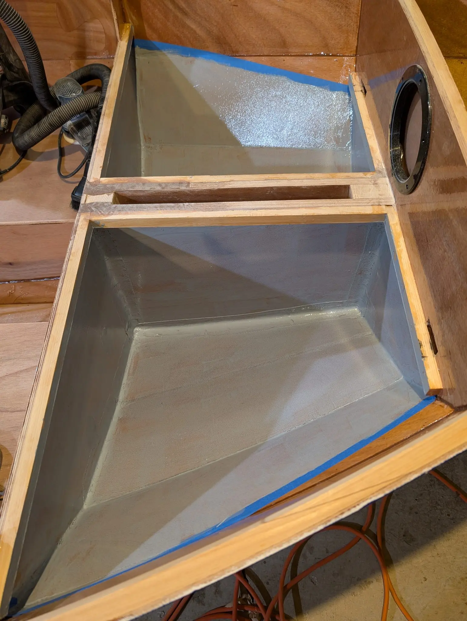
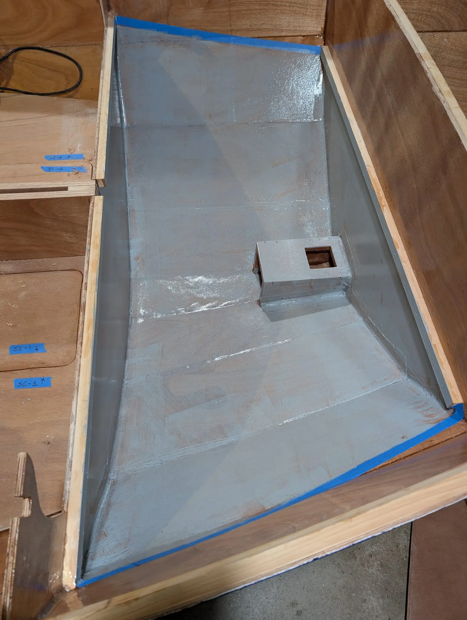
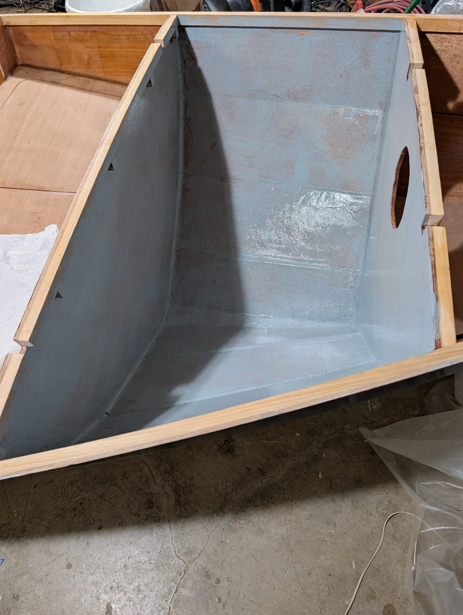
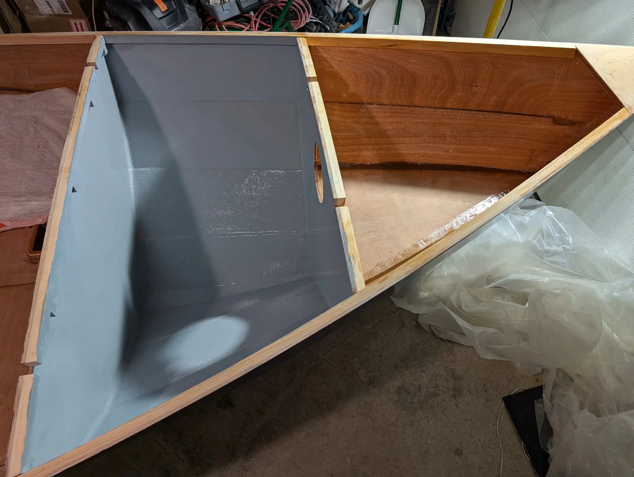
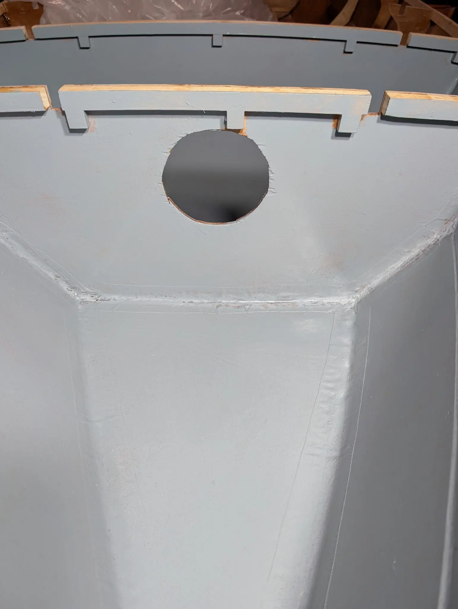
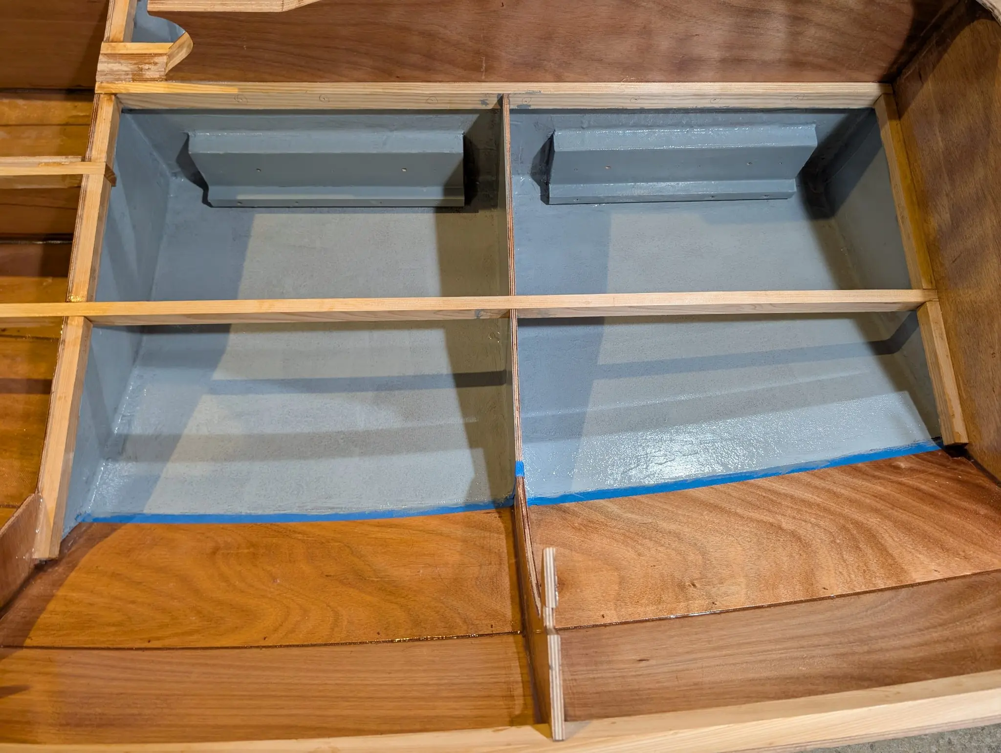
All the interior locker spaces that are normally out of sight were painted to protect the epoxy, to make it more obvious if there is any wear in there, to make it easier to swab out, and because I like the way it looks. The paint is just a latex deck enamel in a color appropriately named "Pacific Storm".
Photo 1 Photo 2 Photo 3
2 Oct 2024Interior & Cockpit
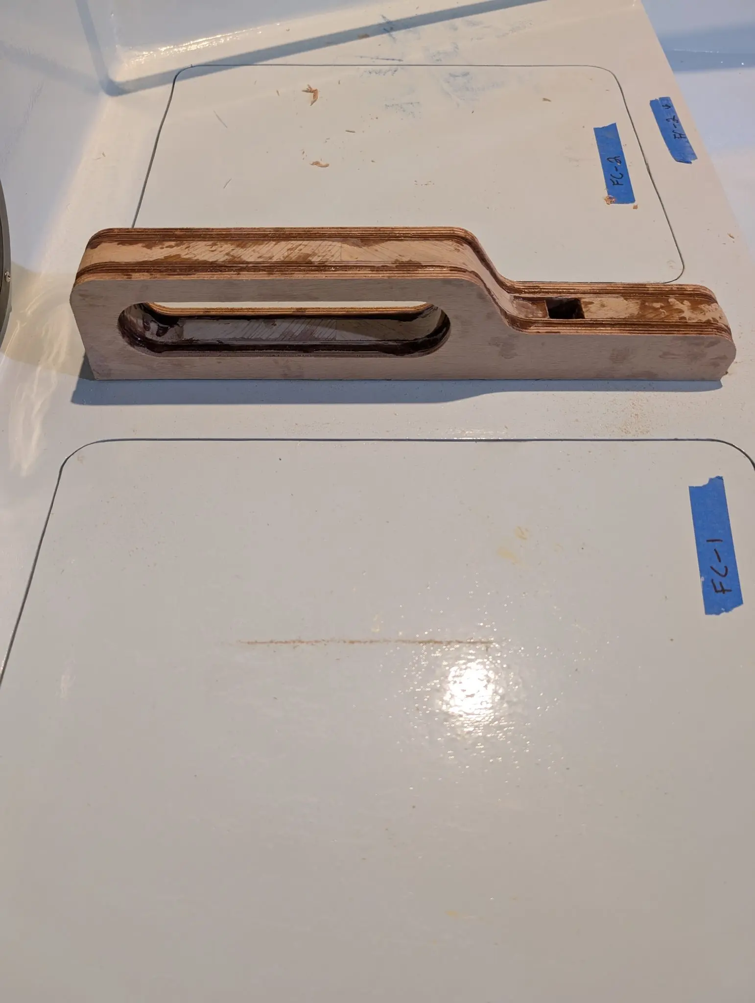
Hatch stiffeners and one of the mast partners
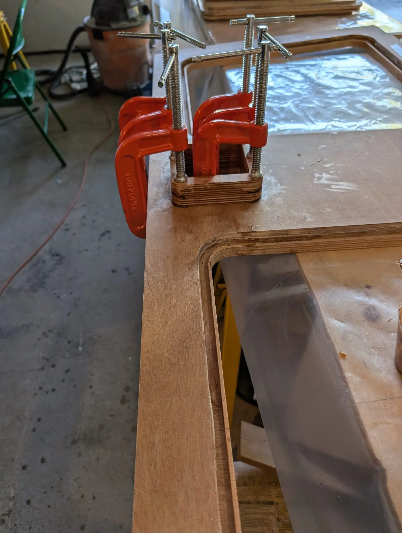
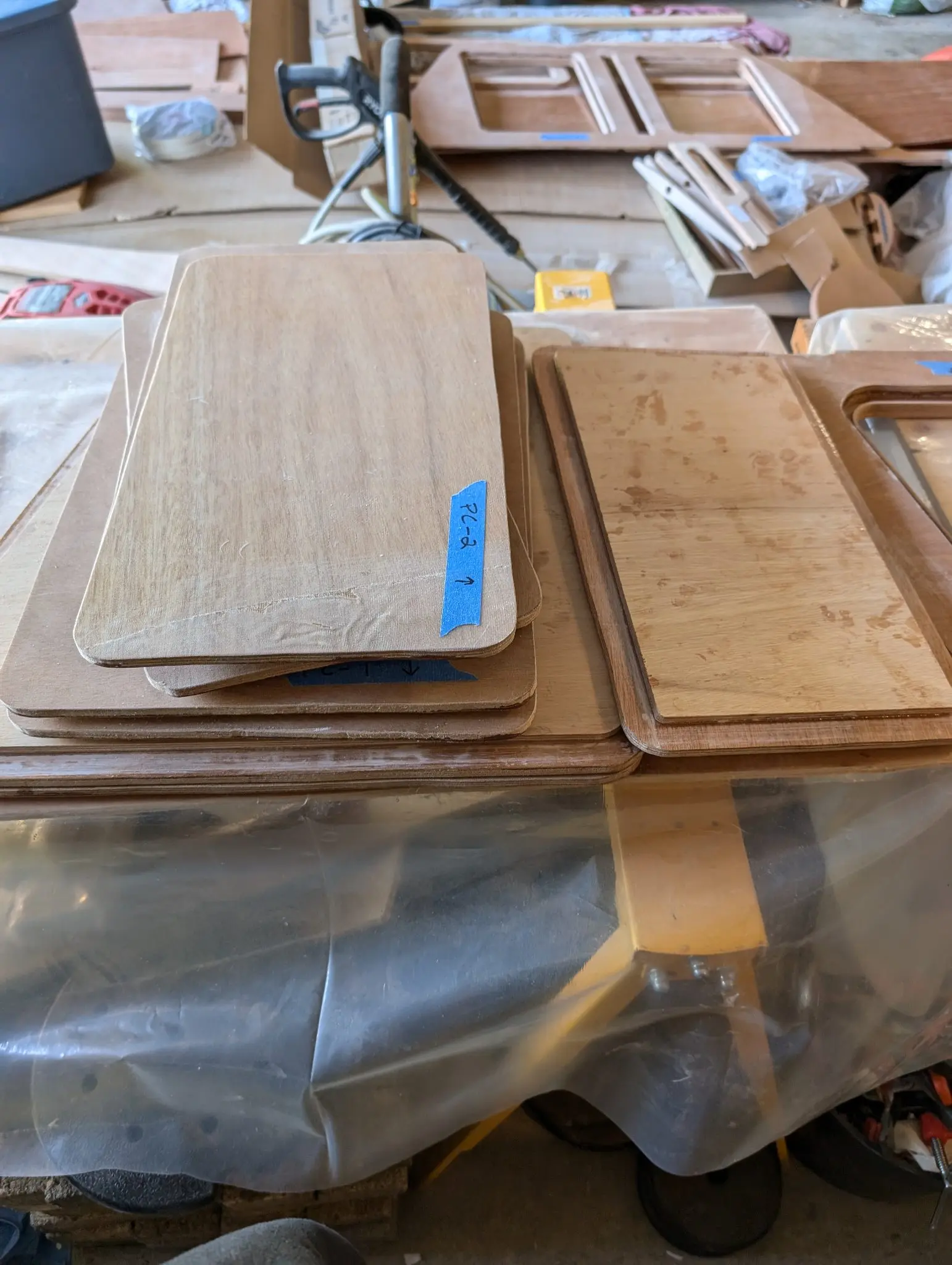
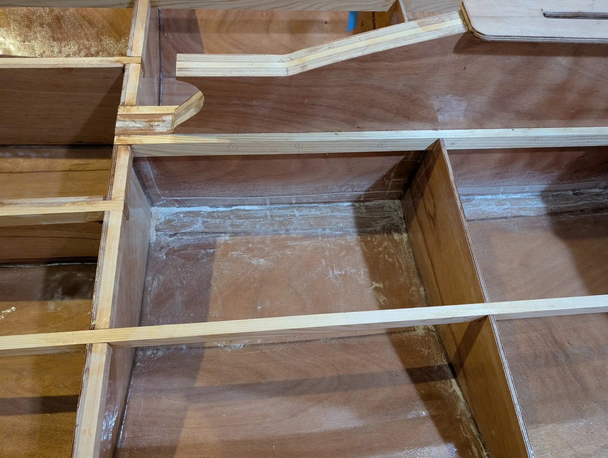
Every hatch requires a stiffener under it to stand up to the load above. The stiffener is smaller than the hatch to make space for a gasket that will make the system (sort of) watertight. Also shown is the installation of one of the two mast partners.
Photo 1 Photo 2 Photo 3 Photo 4
28 Oct 2024Interior & Cockpit
Carrying on with the interior assembly
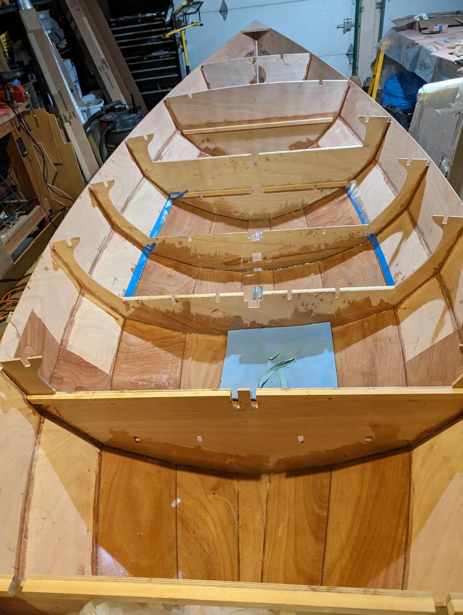
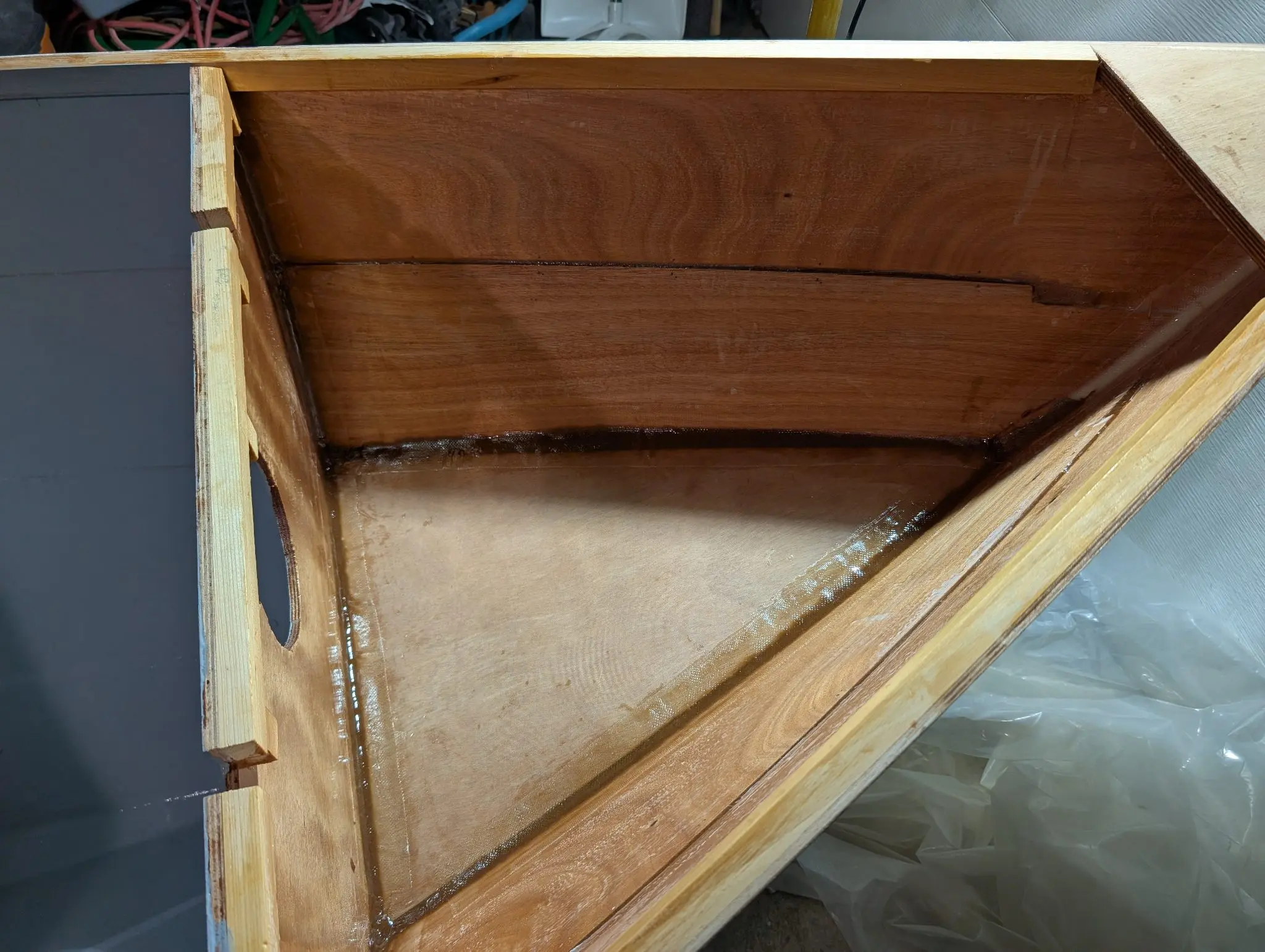
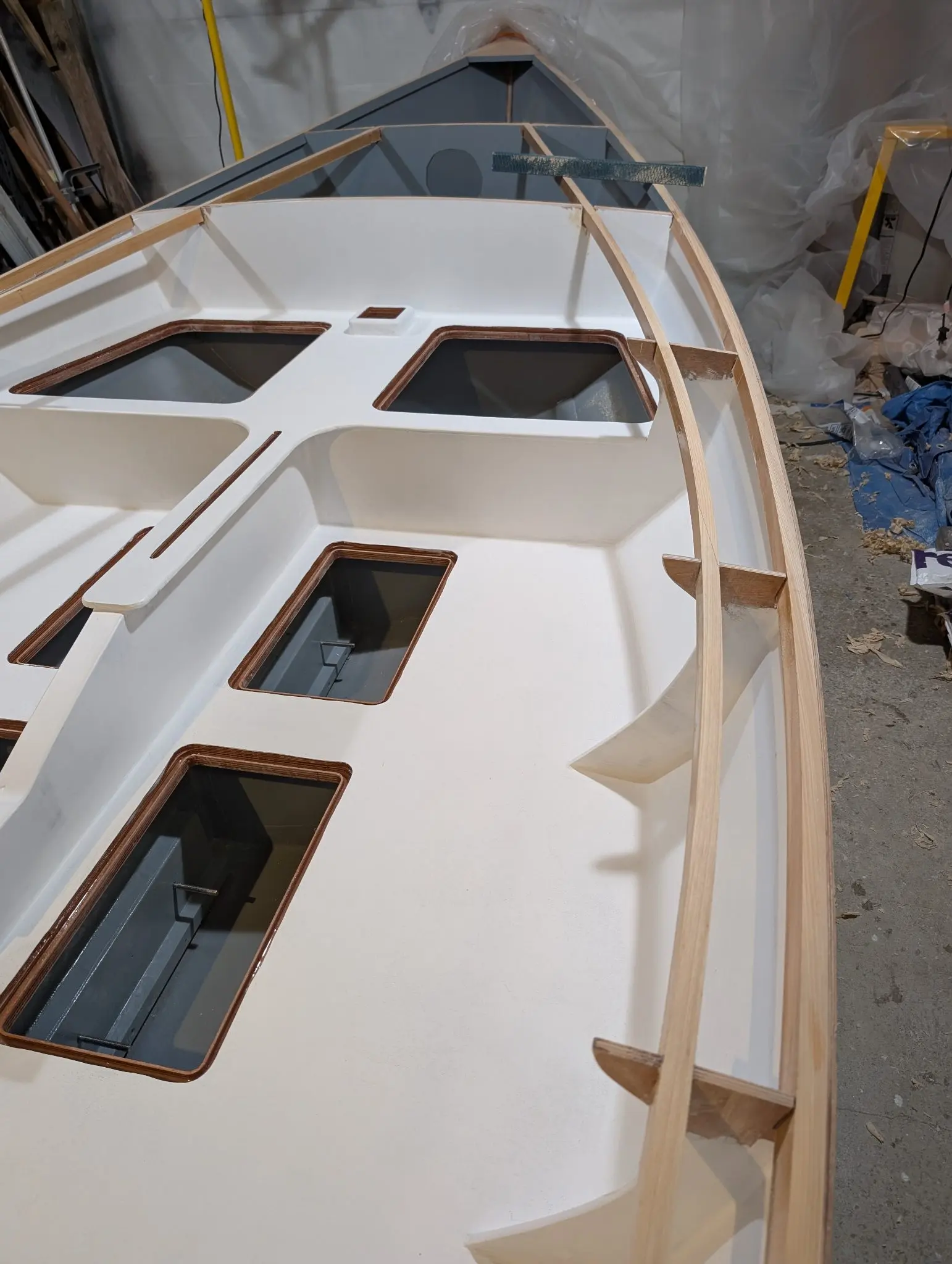
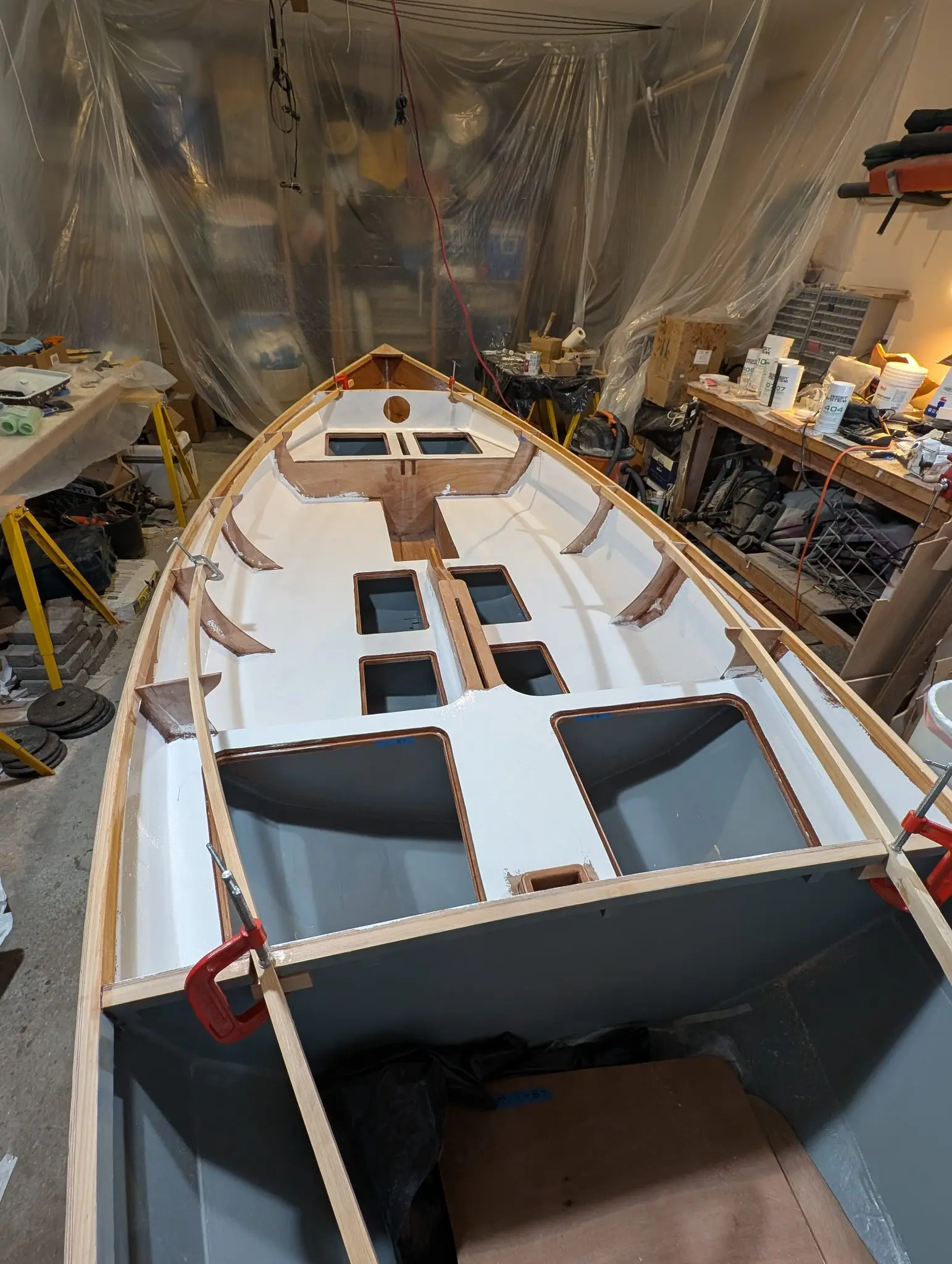
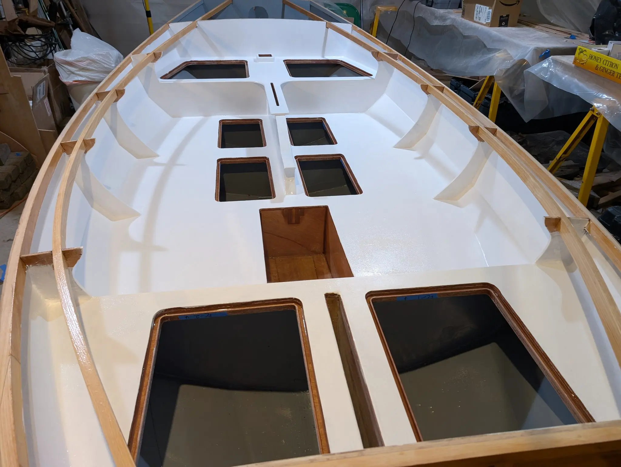
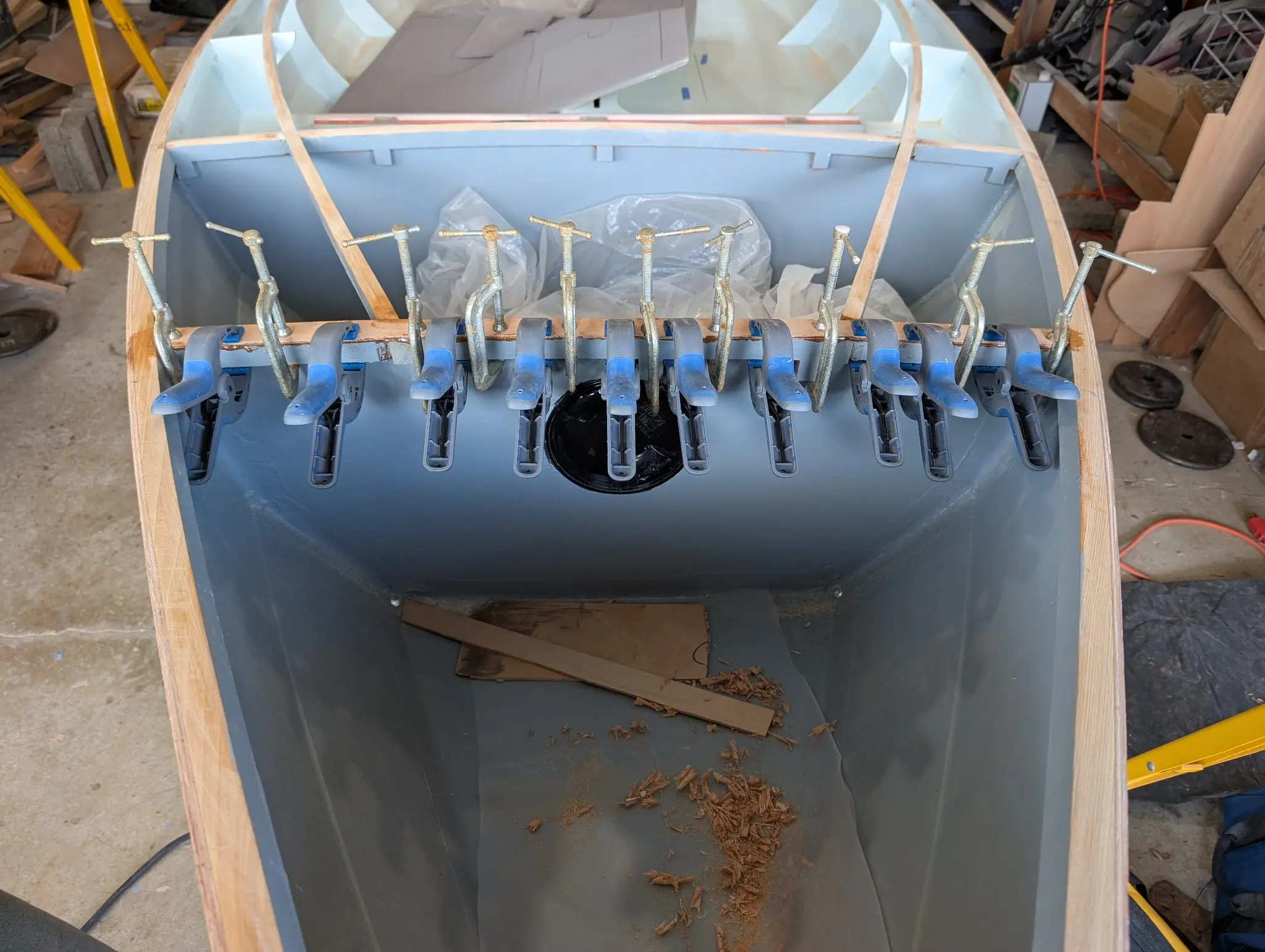
I rolled a saturation coat of epoxy over the interior of the hull and touched up fillets I thought were inadequate. The footwell of the cockpit is enclosed, creating two sealed flotation chambers on either side of the footwell. Here I am gluing the sidewalls of the footwell to the deck supports. I will follow up by filleting the sidewalls along the inner hull and frames. I glued the mast step to the hull, and taped and filleted it for strength. I put an inspection plate in the bulkhead forming one wall of the big stern flotation chamber. I don't expect to use this for storage but I want to be able to air it out and possibly reach into the space to aid in later steps.
Photo 1 Photo 2 Photo 3 Photo 4
4 Nov 2024Interior & Cockpit
Forward and aft cockpit decks installed
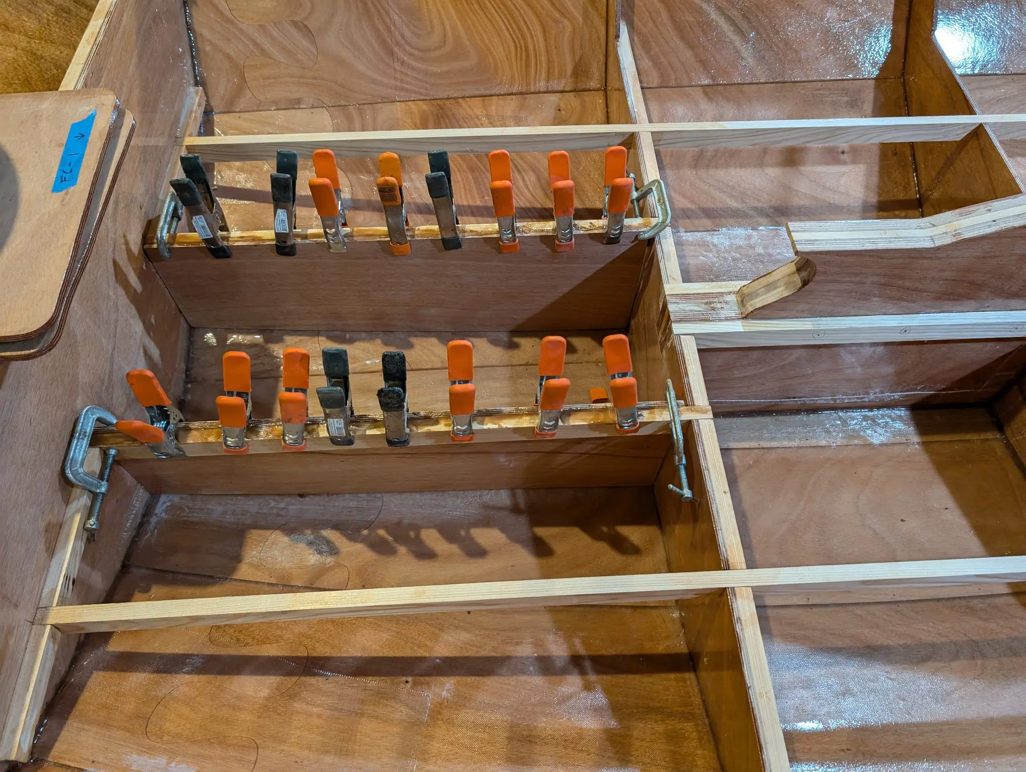
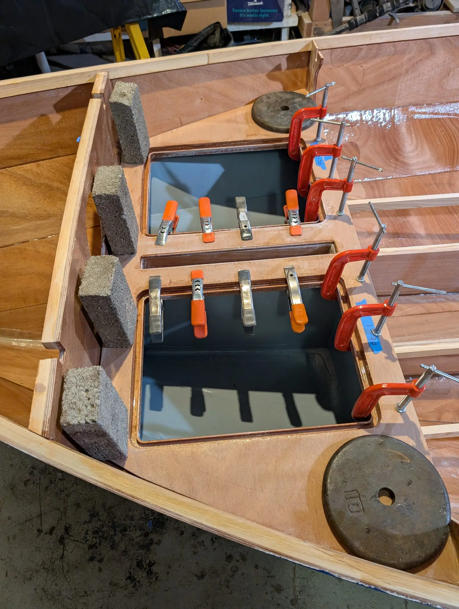
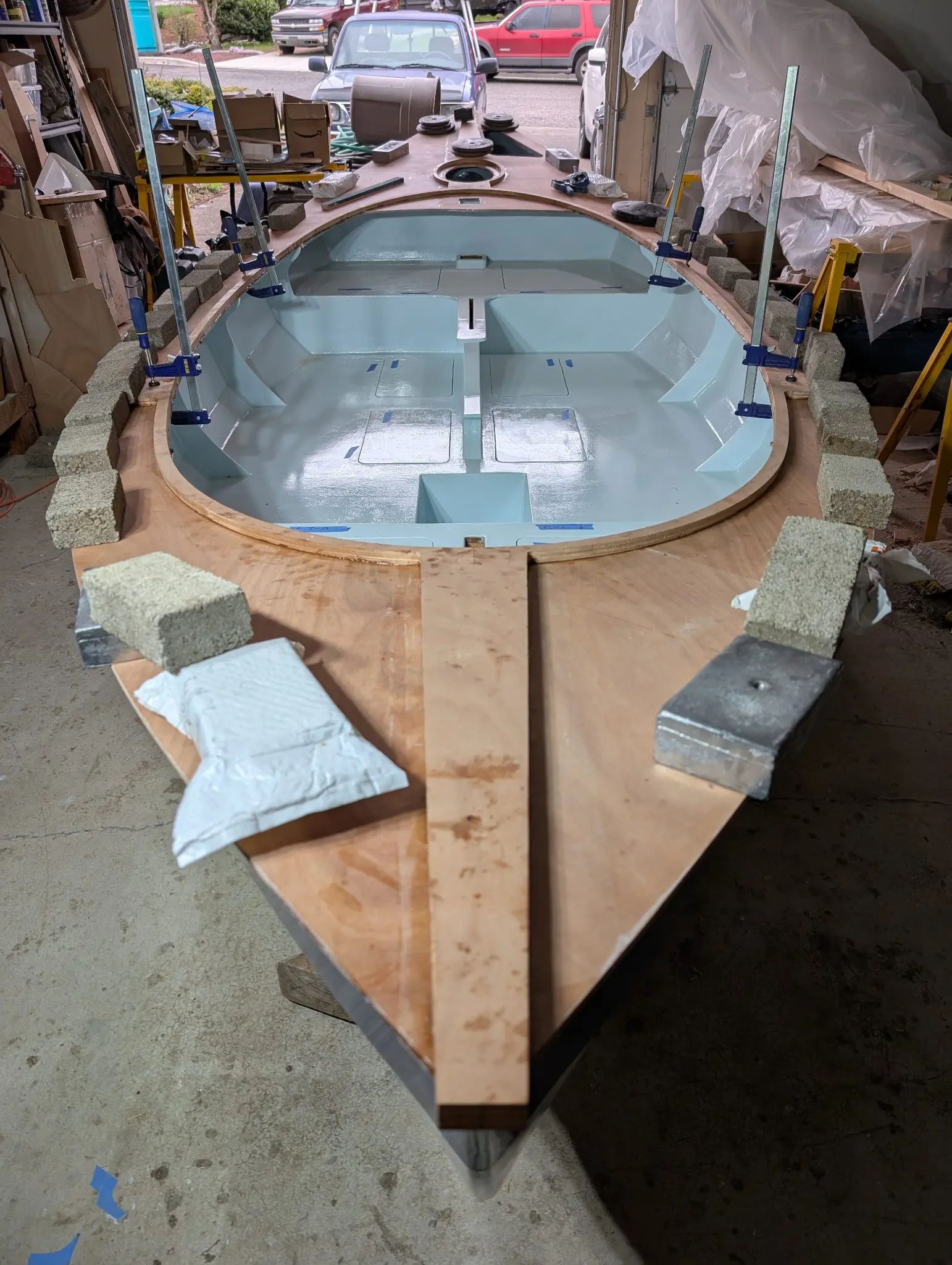
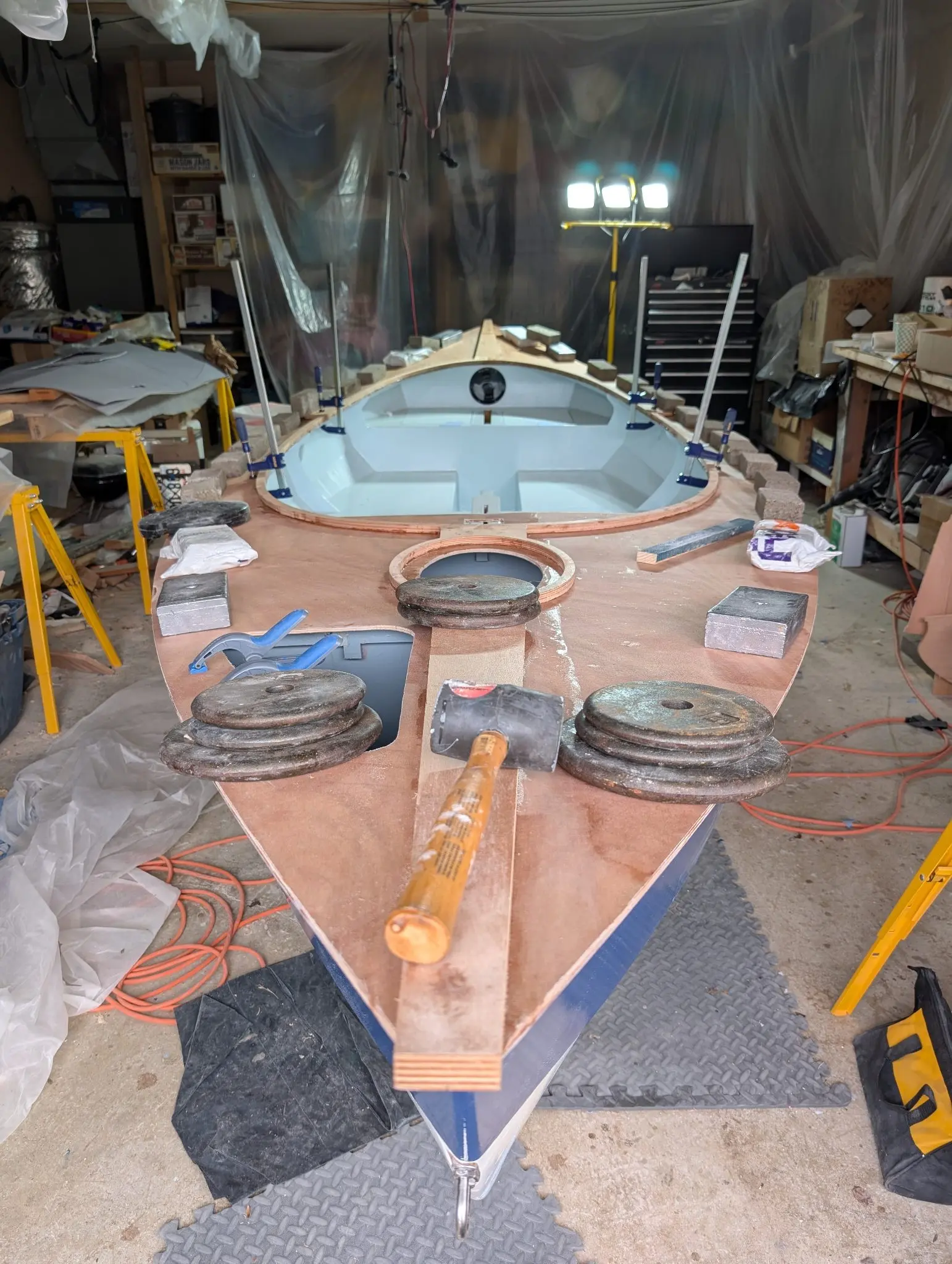
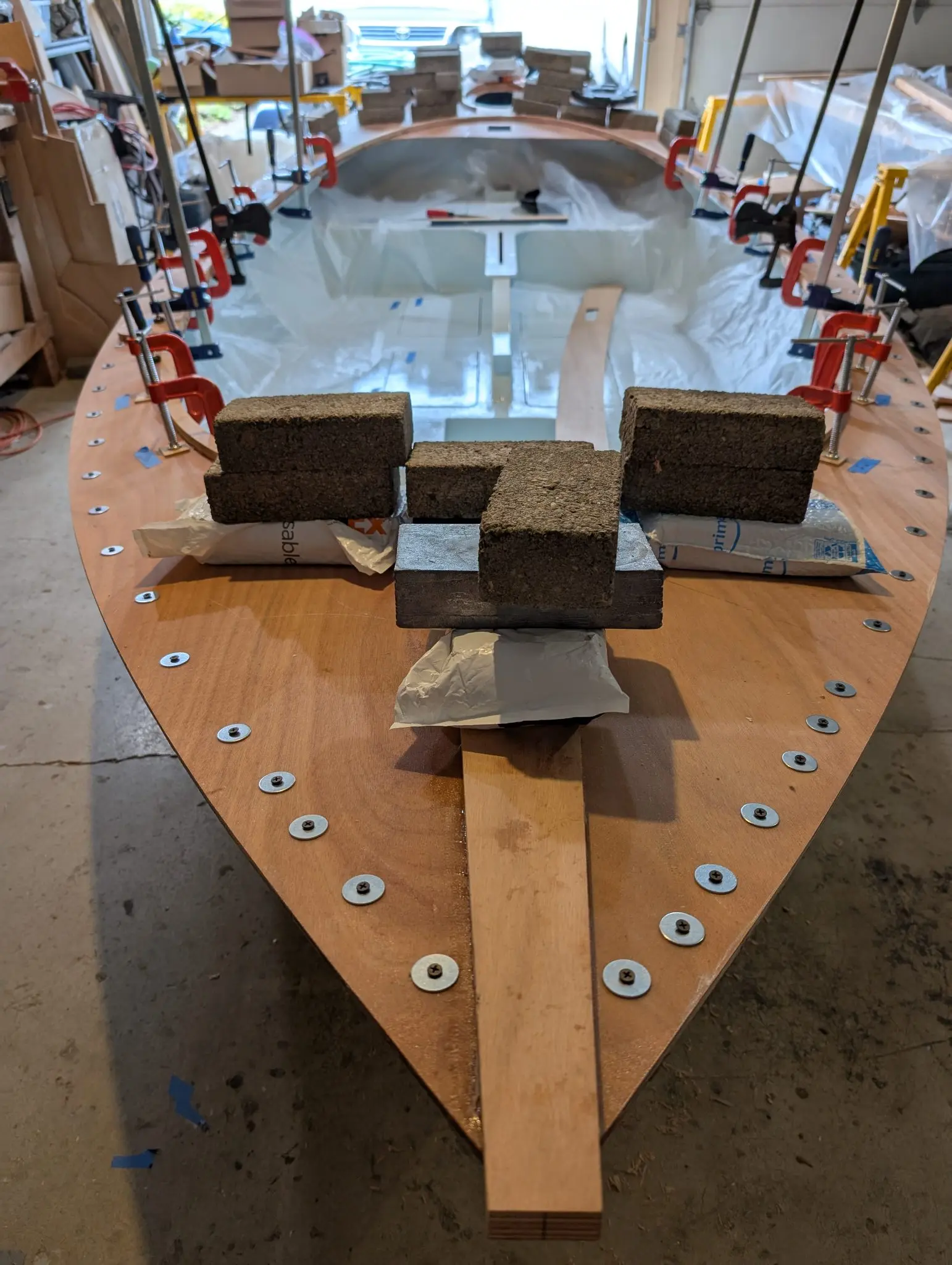
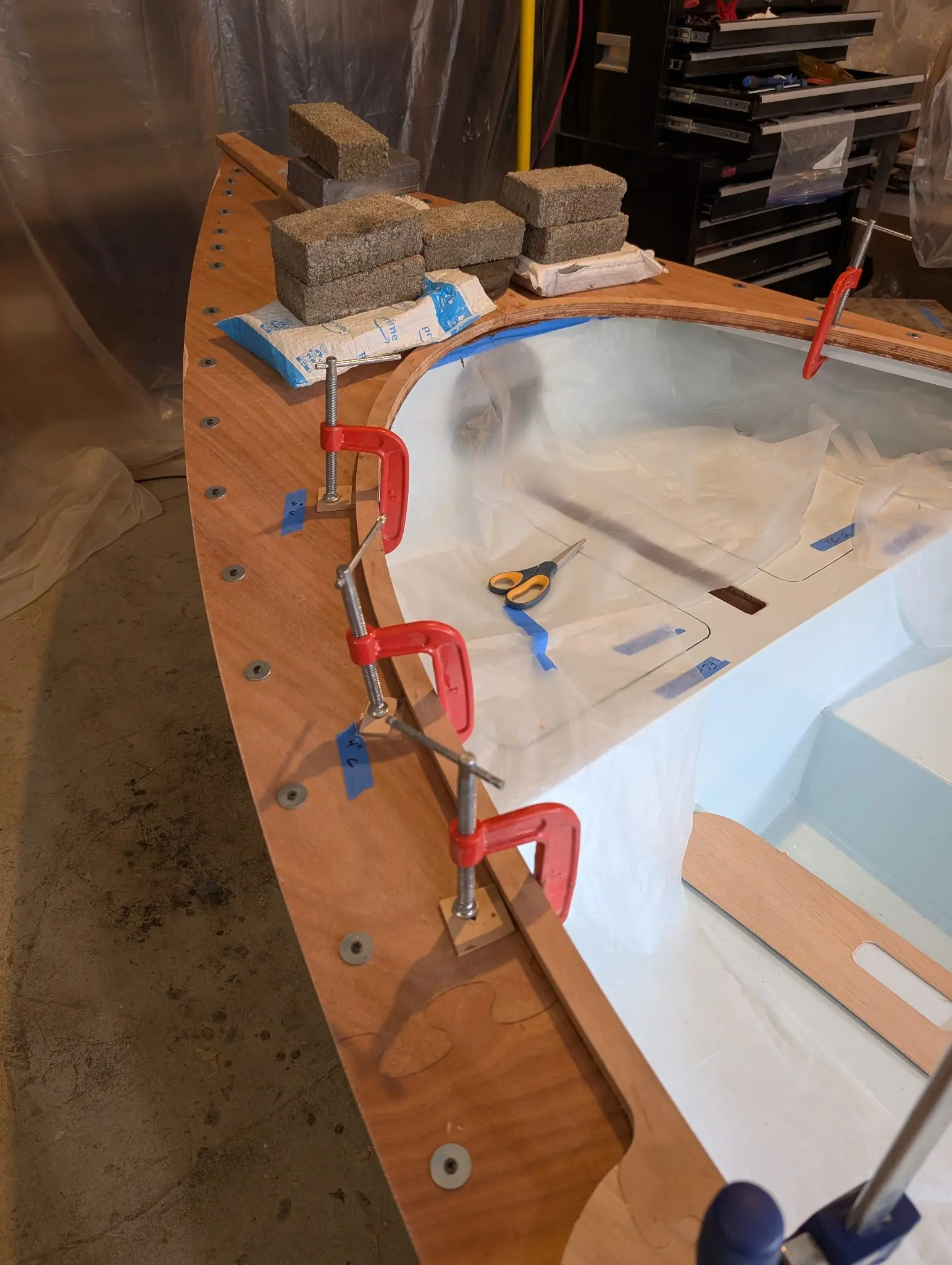
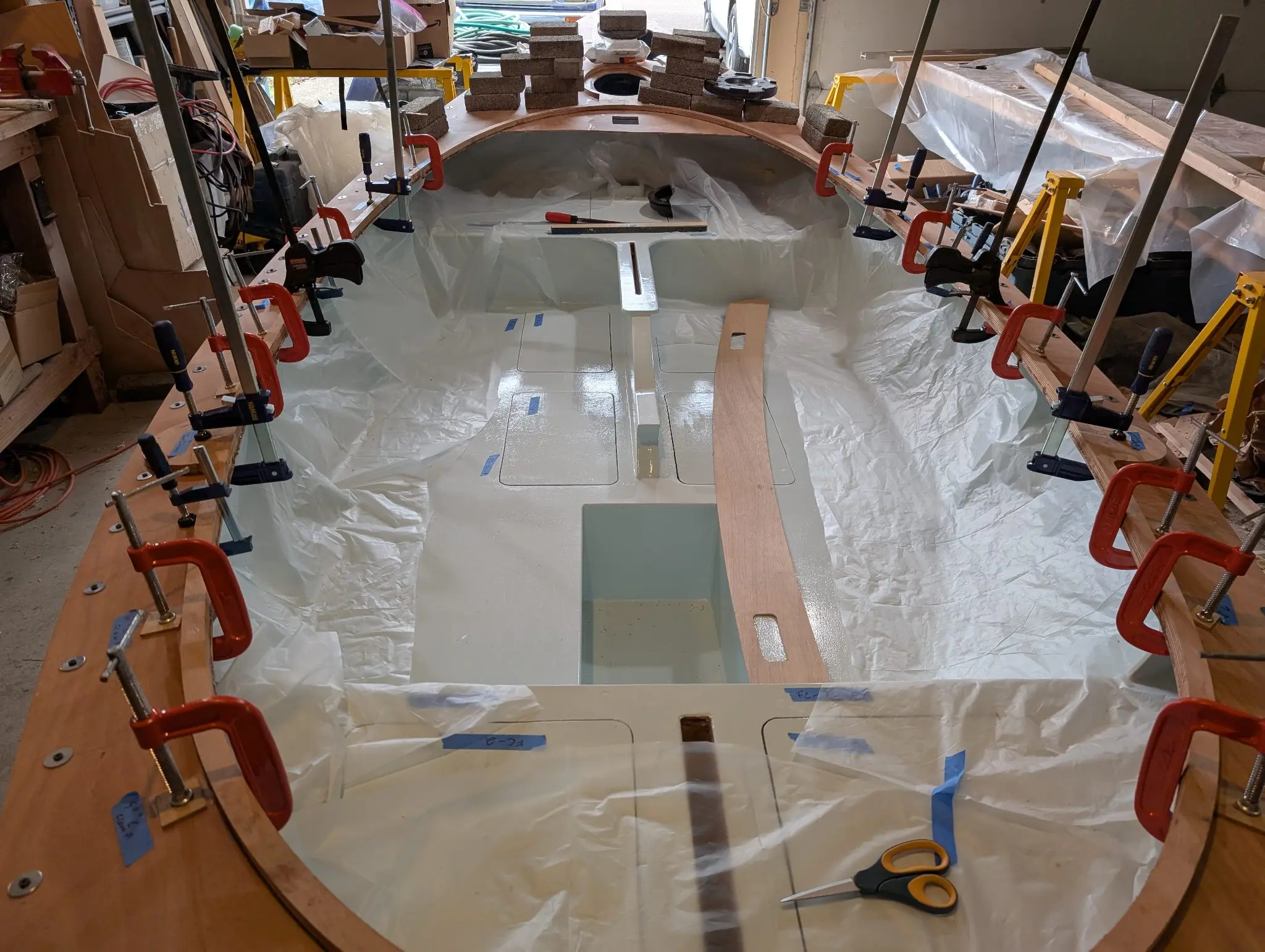
The aft cockpit deck and the forward cockpit deck are epoxied down to the tops of frames or intermediate cleat supports. You only get one shot at this, so it pays to dry-fit everything a couple of times, make some temporary alignment marks, get all your weights and clamps ready, and rehearse it. I brushed epoxy onto the undersides of the decks where they would sit on supports and then squeezed a thick bead of thickened epoxy down on those supports. Then the decks go in, alignment marks are checked, final adjustments are made, and then weights and clamps are placed.
Photo 1 Photo 2
10 Nov 2024Interior & Cockpit
Anchor locker
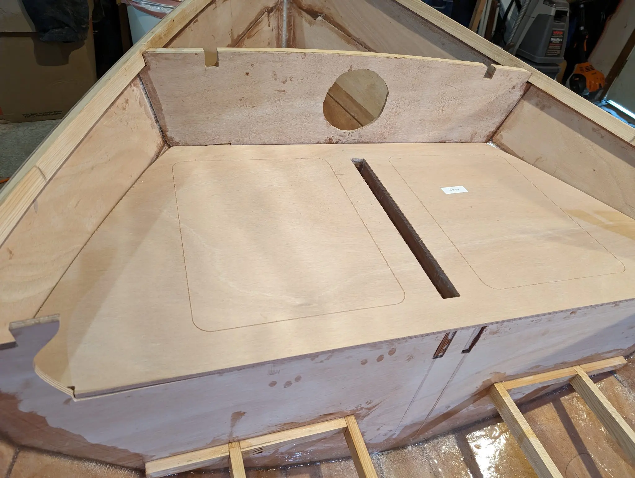
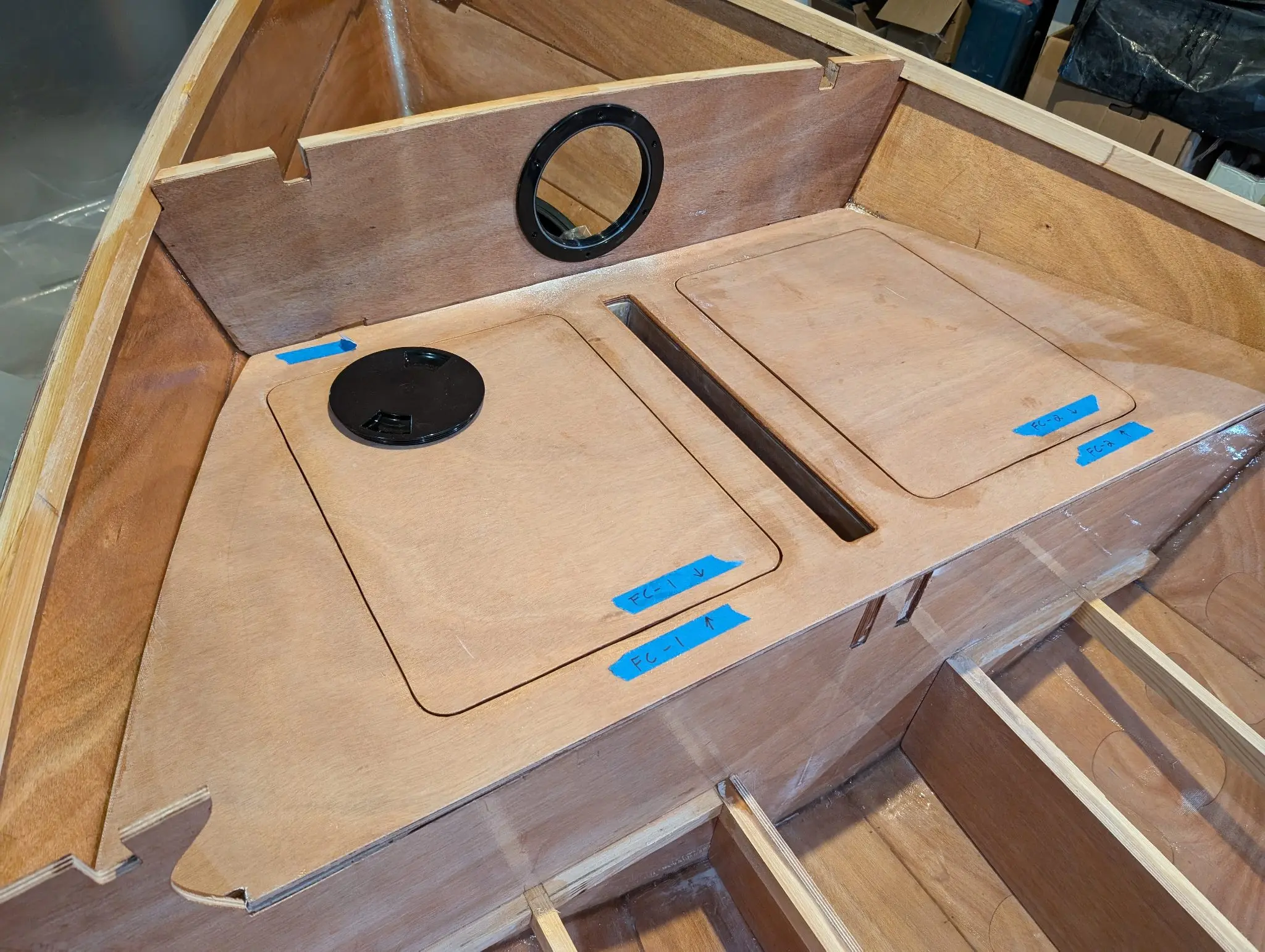
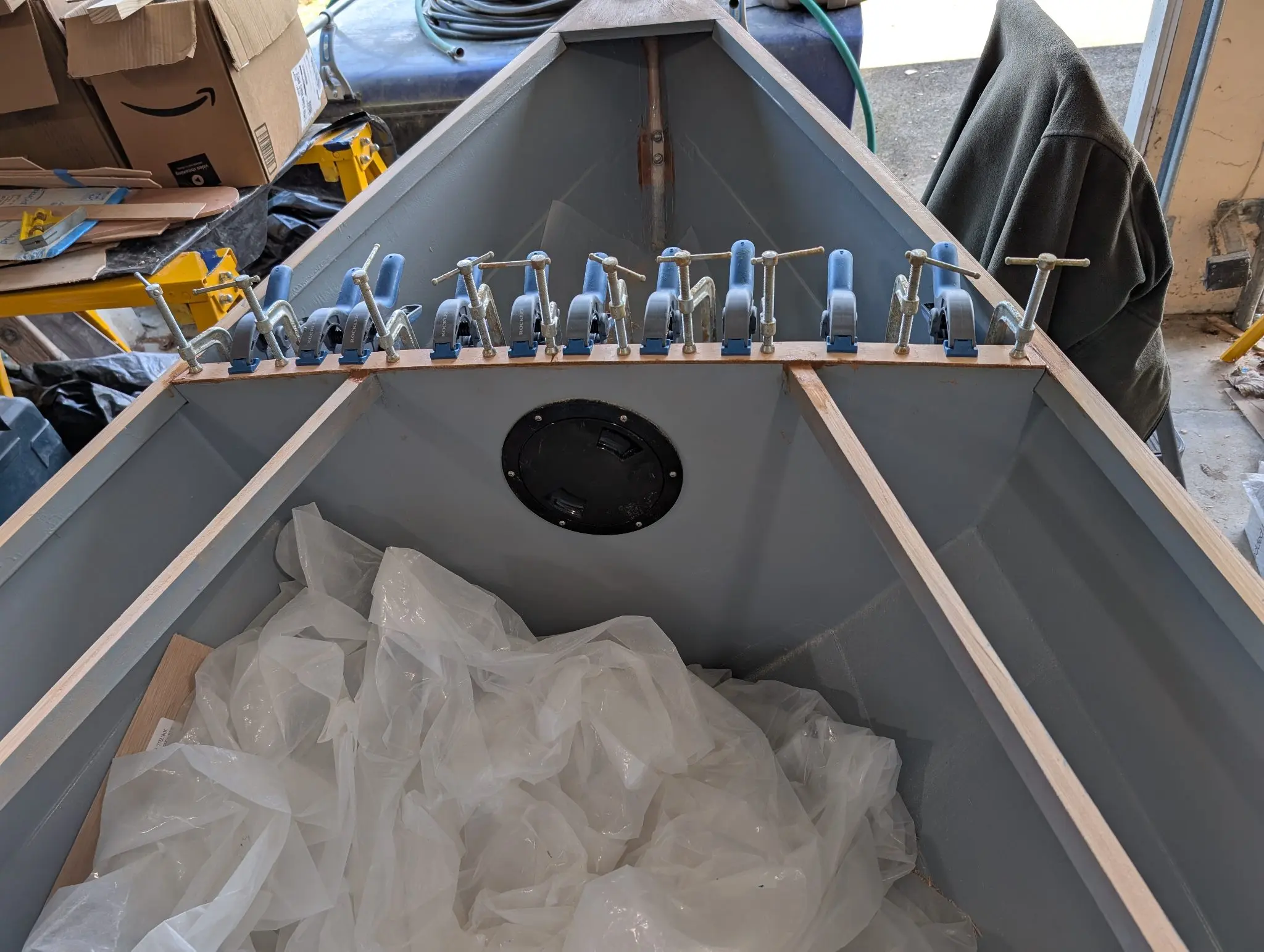
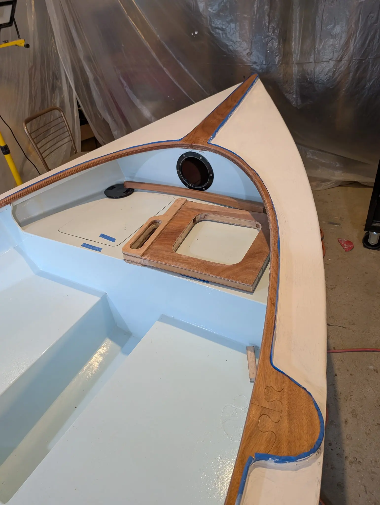
in the bow a small deck is put over the flotation chamber to create the anchor locker. The anchor itself will be hanging from a pulpit on the bow. The rode will be stored in this locker, with two holes at the lowest points of the locker on both sides to provide drainage for any water brought up when the anchor is weighed. Also, I am terrible at cutting round holes. This one will have a round inspection plate installed. I am not quite sure CLC put this here, since there will be another way into that space. Ours is not to question why....
Photo 1 Photo 2 Photo 3
25 Nov 2024Interior & Cockpit
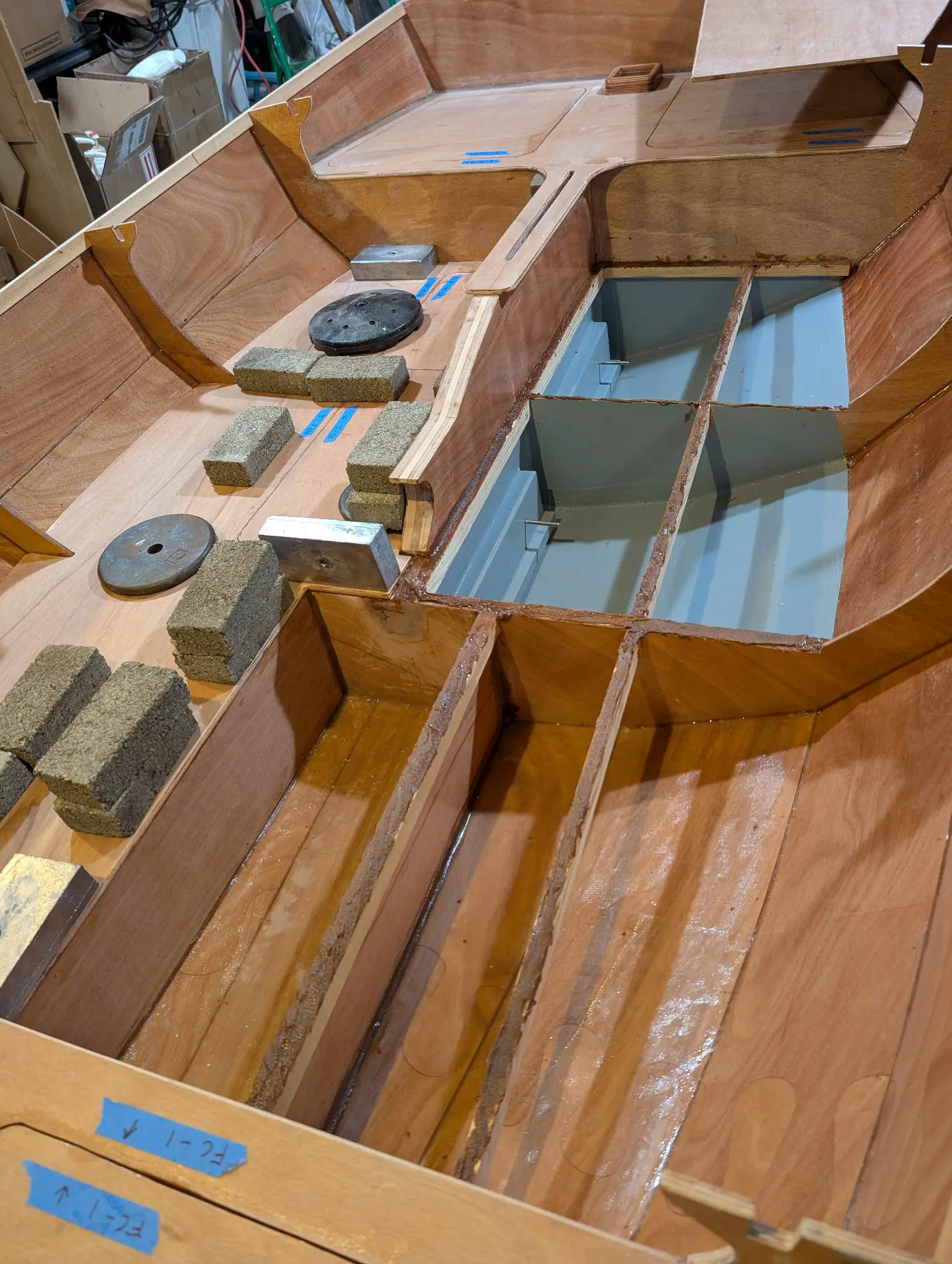
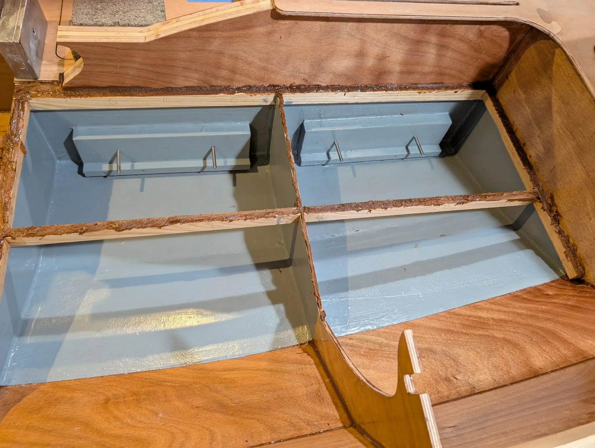
Securing 200 lbs of lead ballast
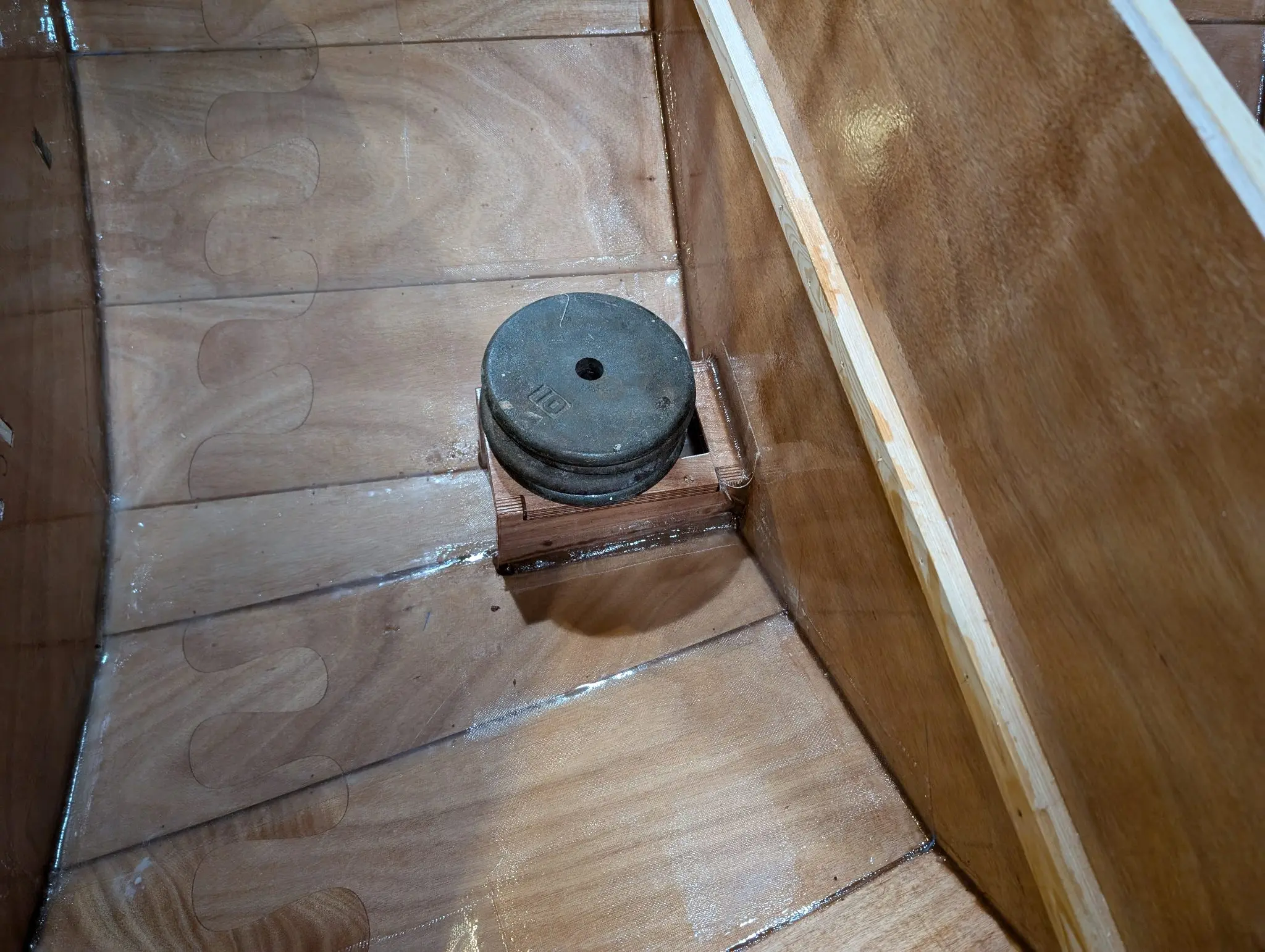
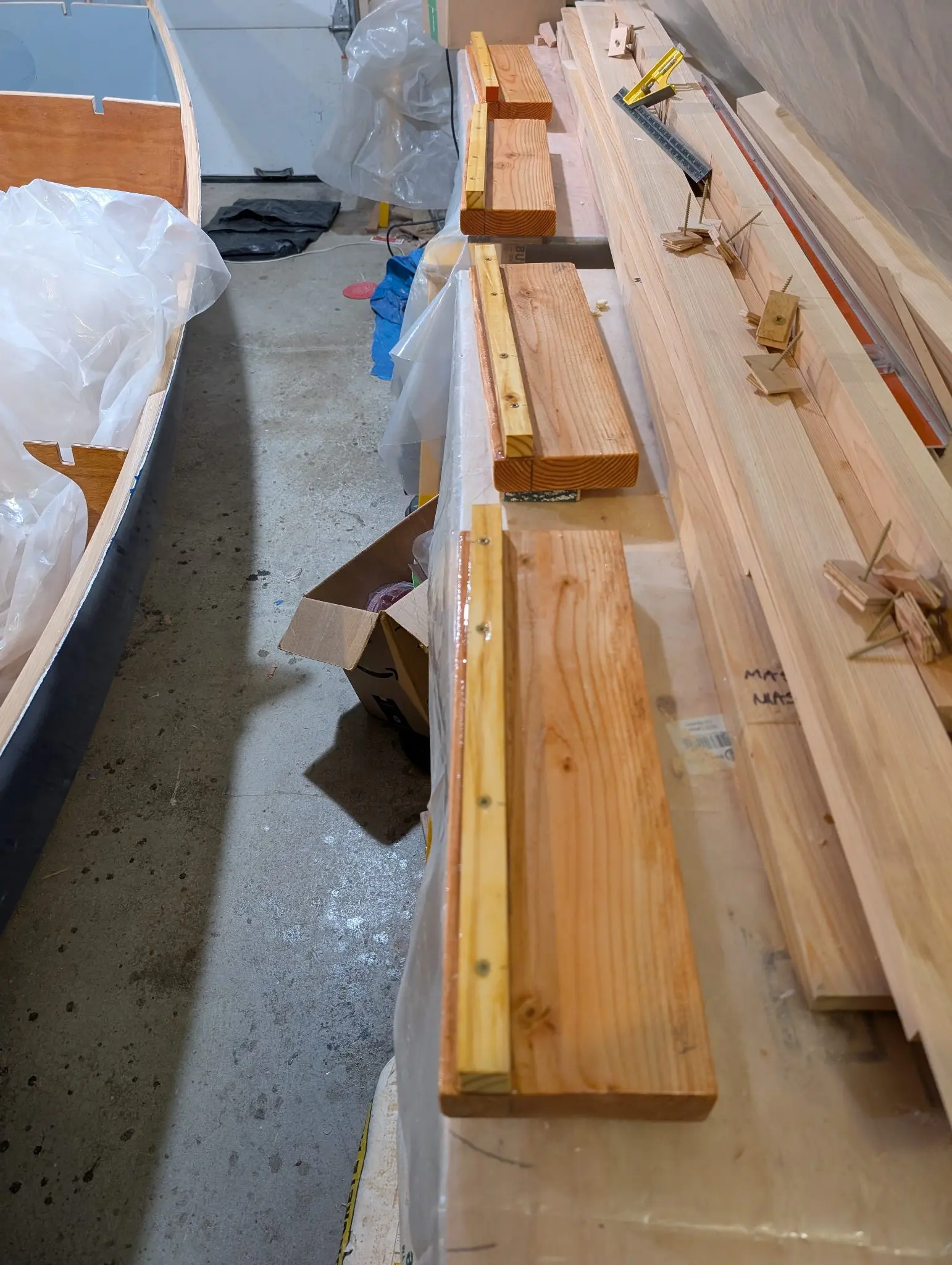
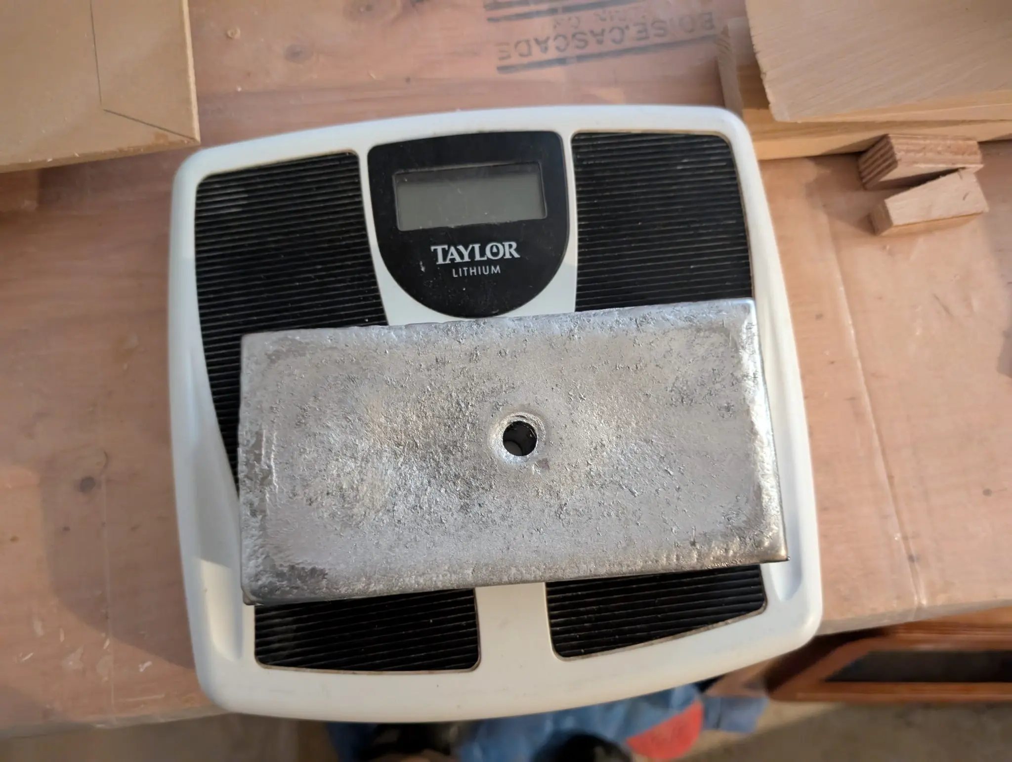
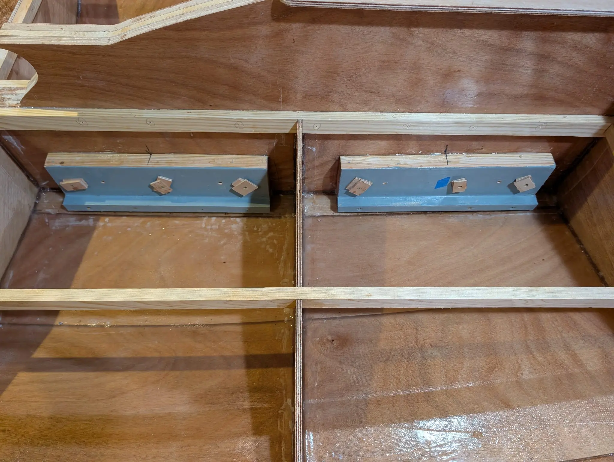
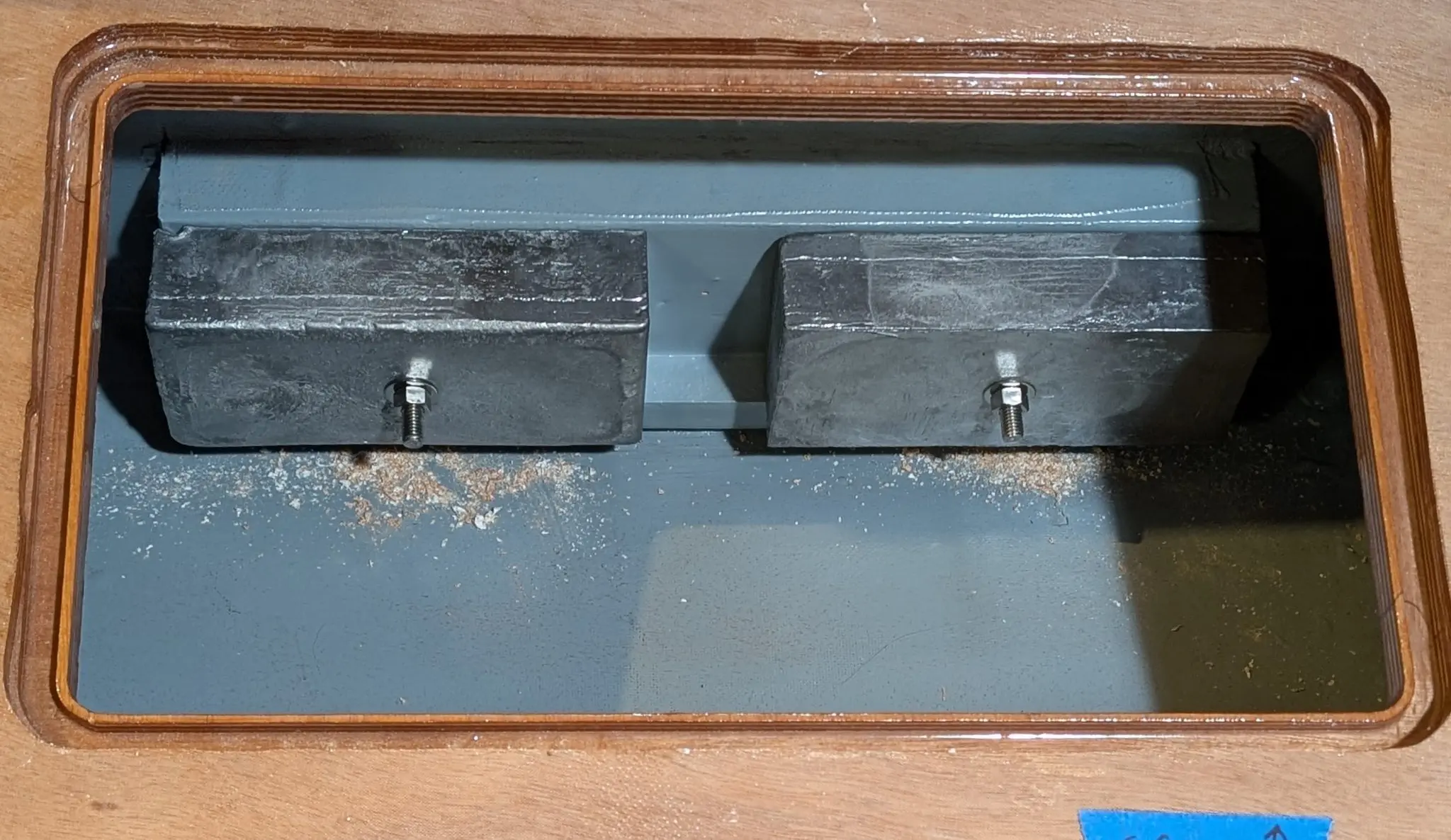
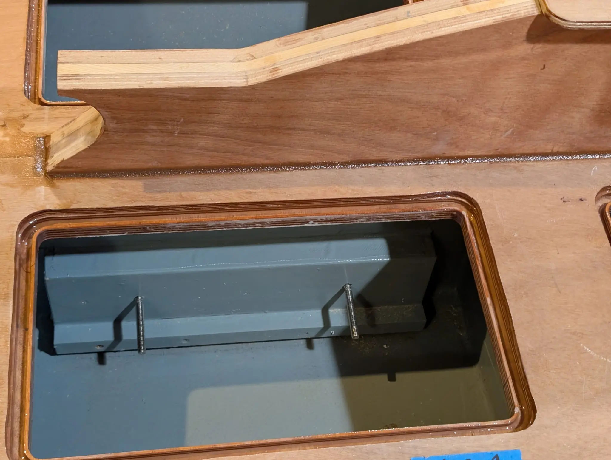
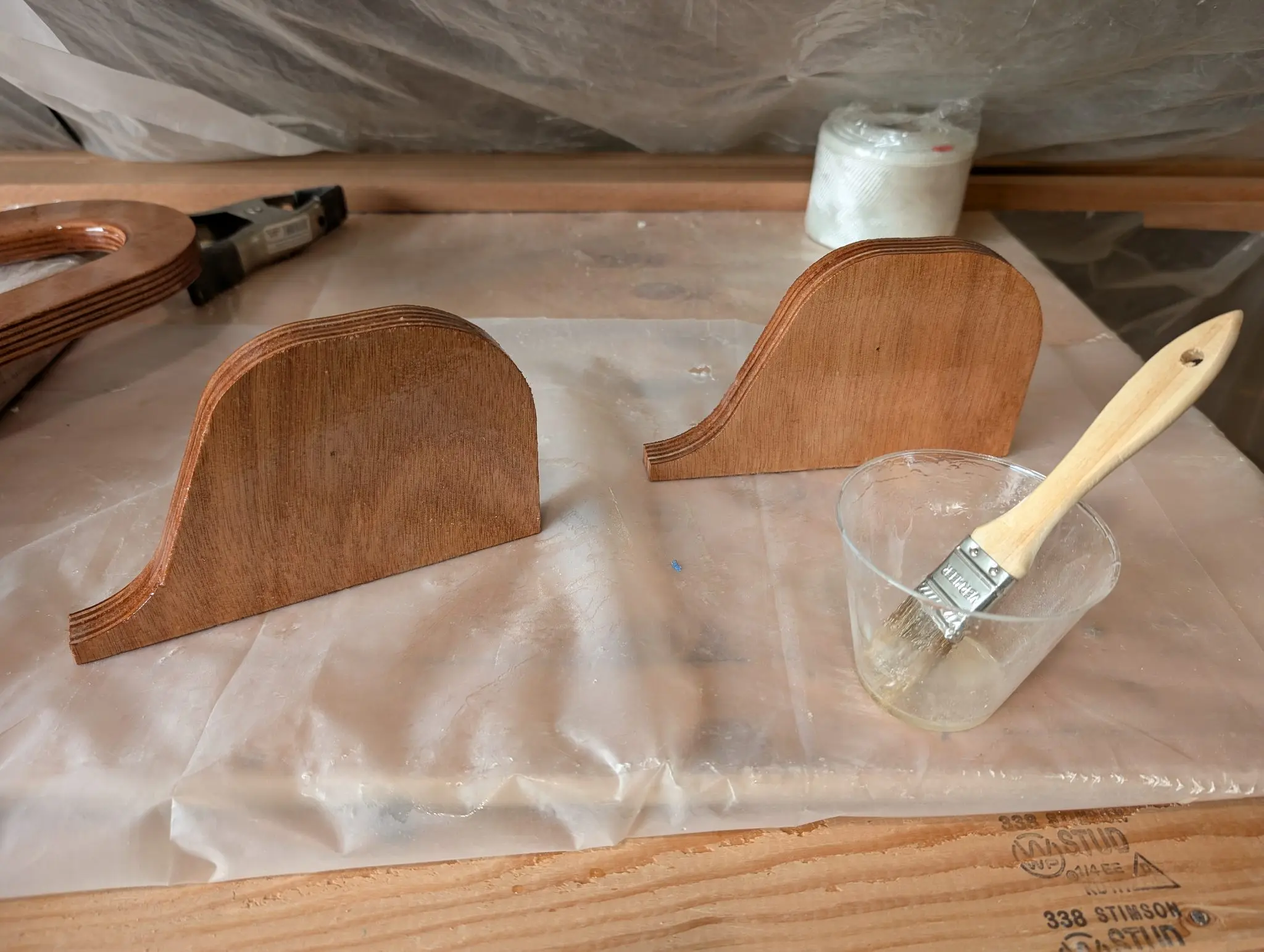
CLC calls for 200 Lbs of ballast for this boat, especially when lightly loaded. I worried and fretted about this a LOT. Finally, I decided to buy lead bricks from Roto Metals (https://rotometals.com). I had worried about shipping lead, but they just chuck each brick in a USPS fixed-price box and send it first-class mail. It seems a little unfair but.... Each brick comes pre-drilled, so I built wooden brackets and put stainless steel studs in them. Then those were attached to the centerboard trunk with ss screws, epoxy, and fiberglass tape. The bricks are mounted on the studs and held with ss lock washers and wing nuts (hex nuts shown in the photo were replaced with wing nuts later). I did it this way to make sure the ballast wouldn't shift if I laid the boat over, and to make it easily removable for trailering.
Photo 1 Photo 2 Photo 3 Photo 4 Photo 5 Photo 6
3 Dec 2024Interior & Cockpit
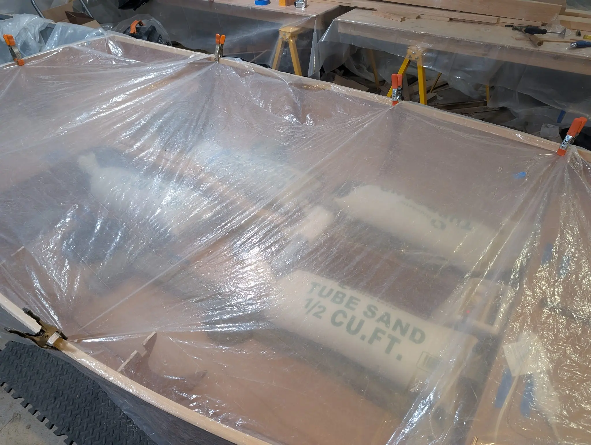
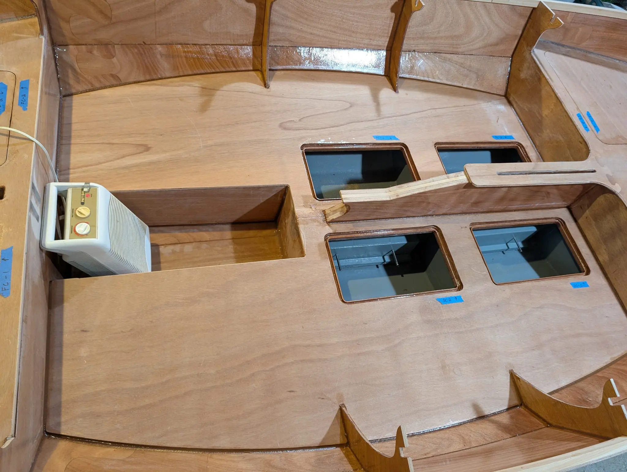
Installed main cockpit decks
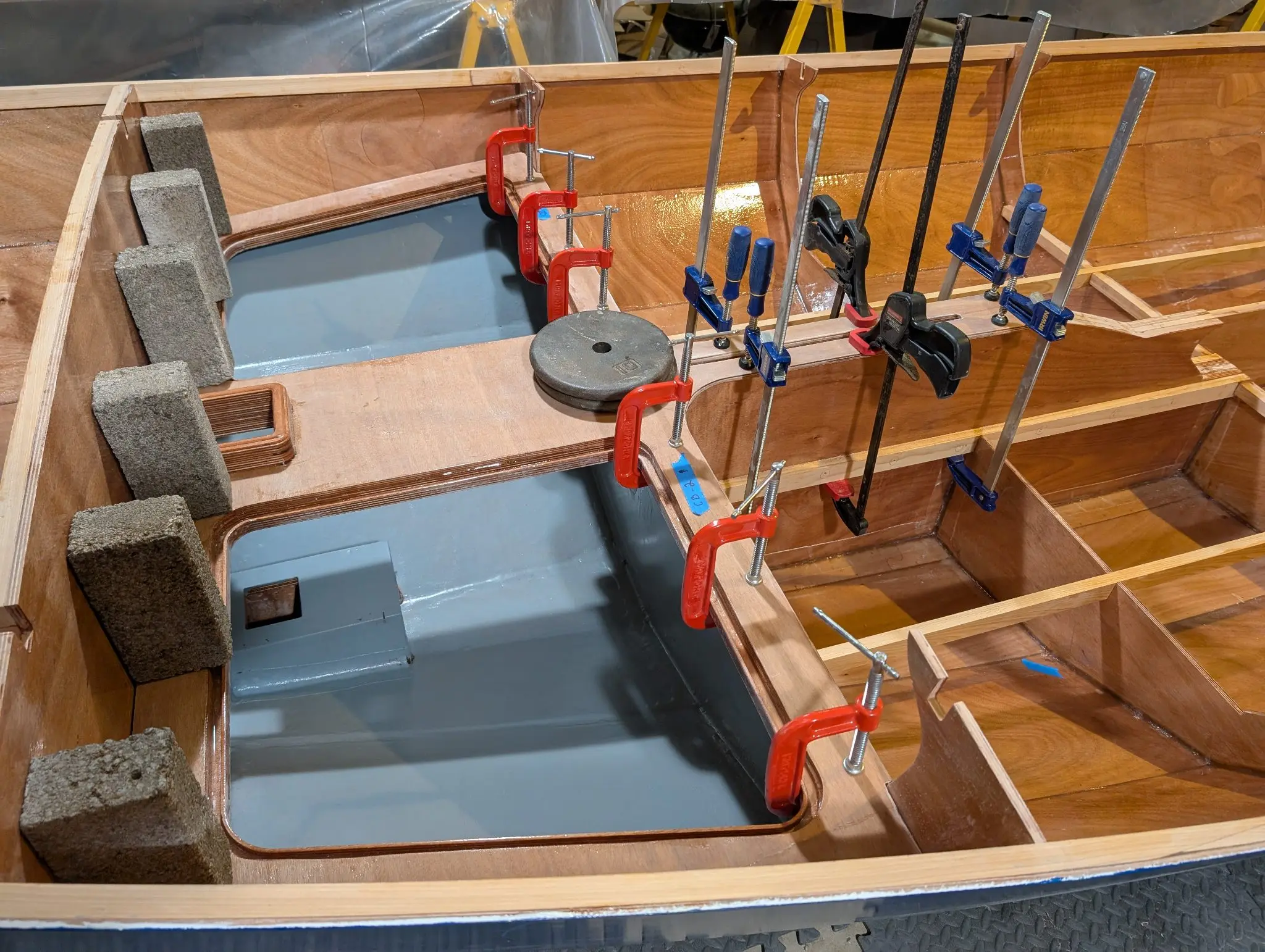
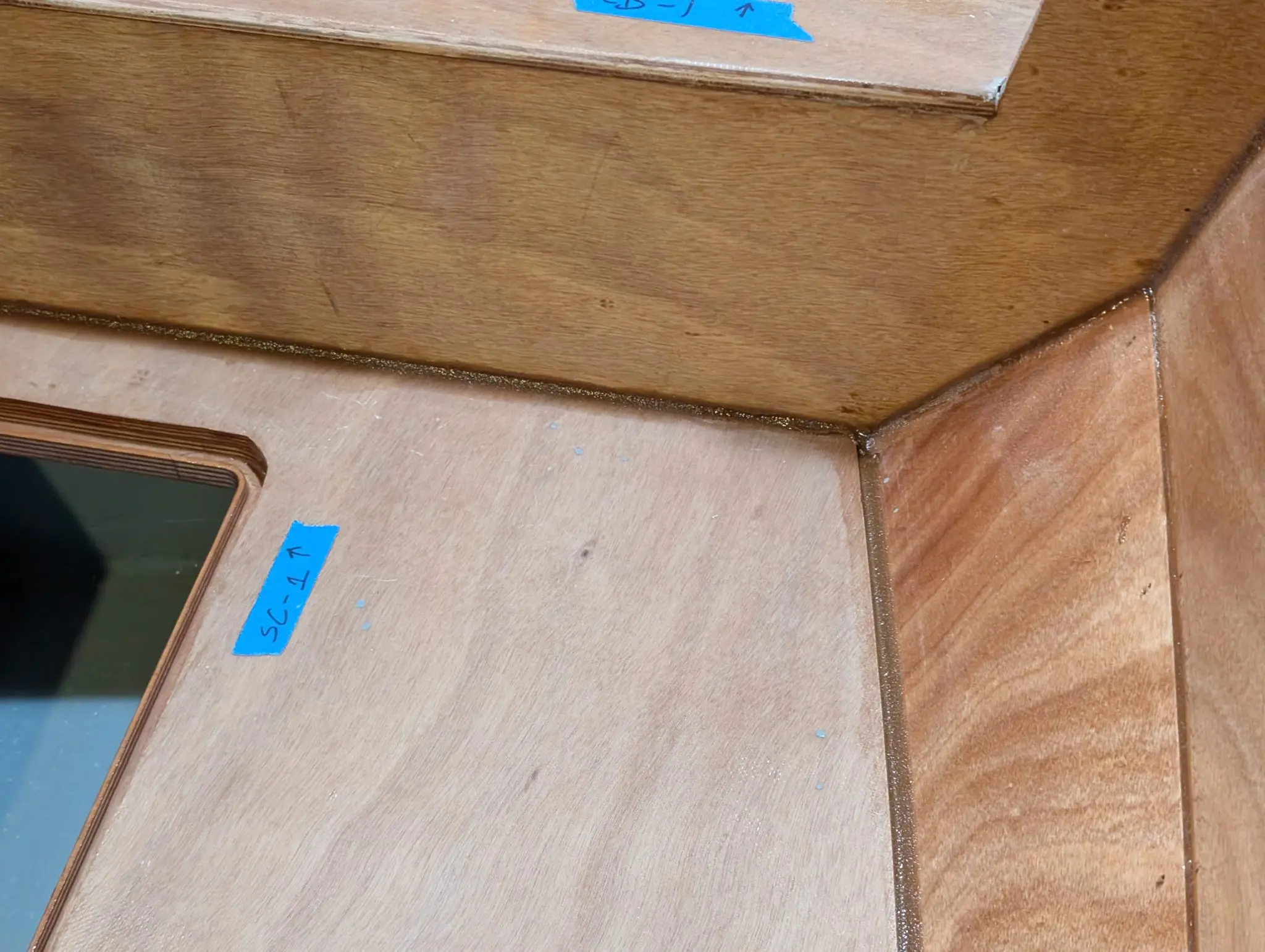
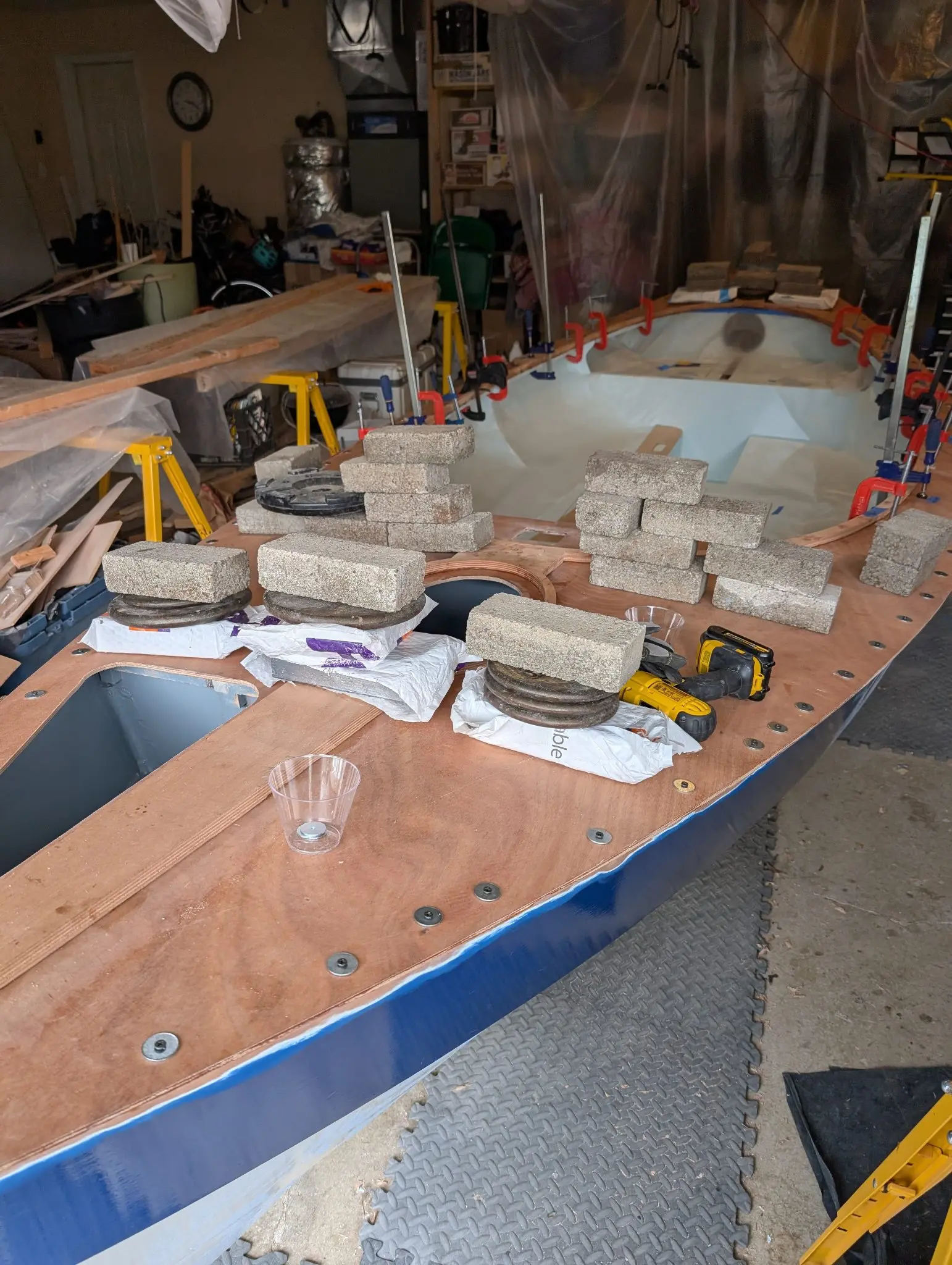
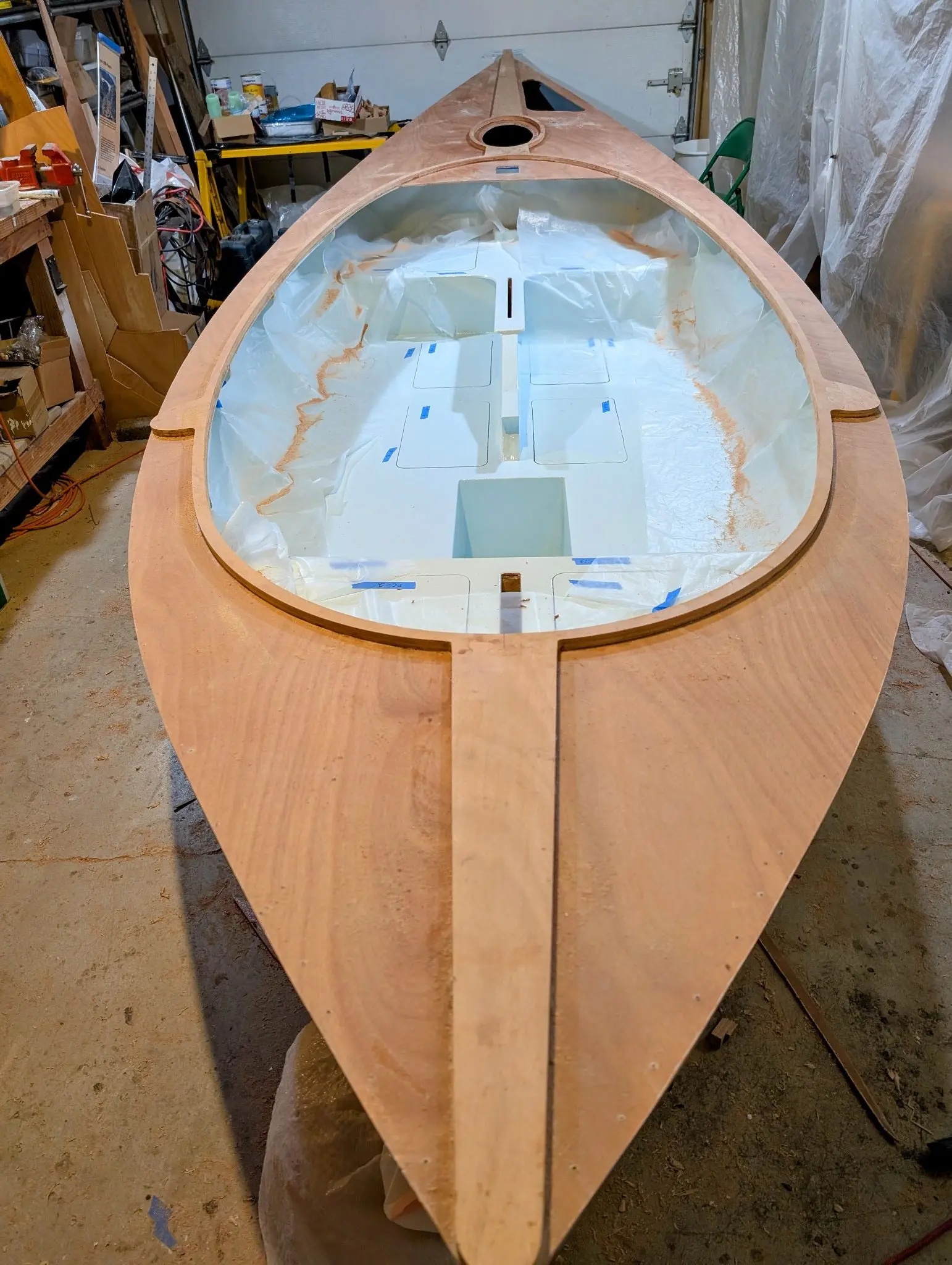
The two main cockpit decks are now epoxied to their supports. This is similar to the two other cockpit decks, except that these have no convenient spots to clamp them down. They are held in place with a bunch of weights ( lead bricks, steel plates, bags of sand). It's cold this time of year, and my workspace is unheated, so I draped it in plastic with a space heater inside. Then all the decks are filleted to keep water from standing anywhere and increase the strength of the join.
Photo 1 Photo 2 Photo 3 Photo 4 Photo 5 Photo 6
Chapter 09
Rig & Spars
Mast, boom, standing and running rigging, sails.
3 daysfrom January 2025
16 Jan 2025Rig & Spars
Building spars (Part 1 of several)
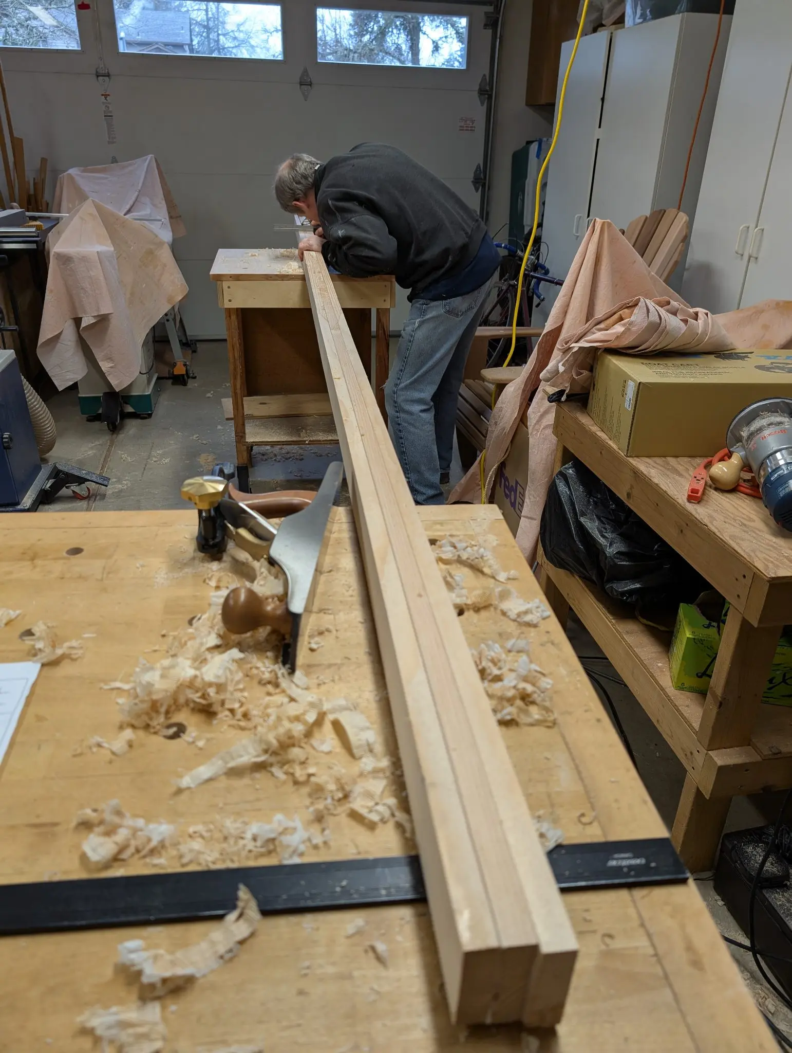
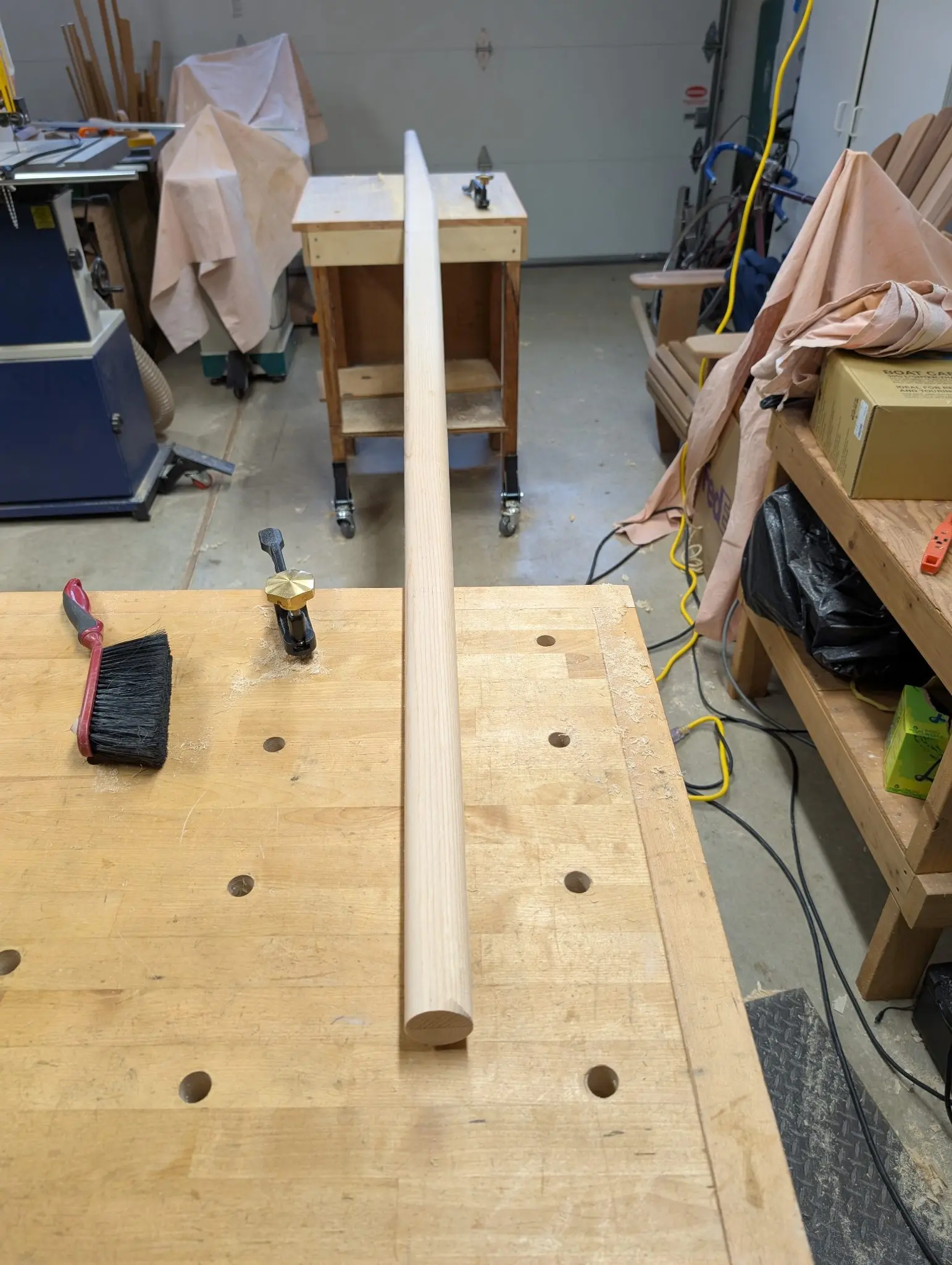
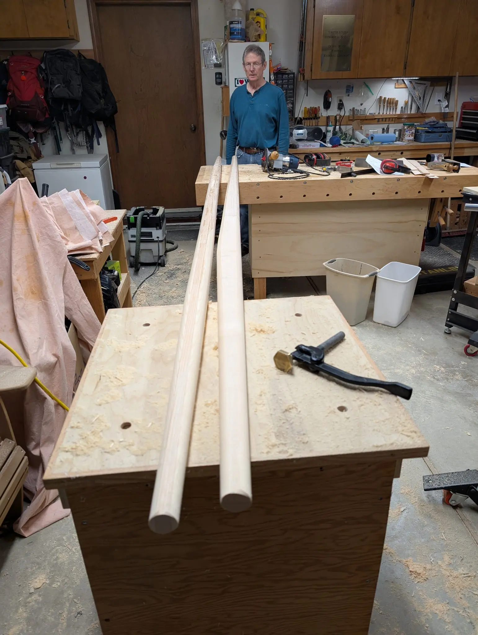
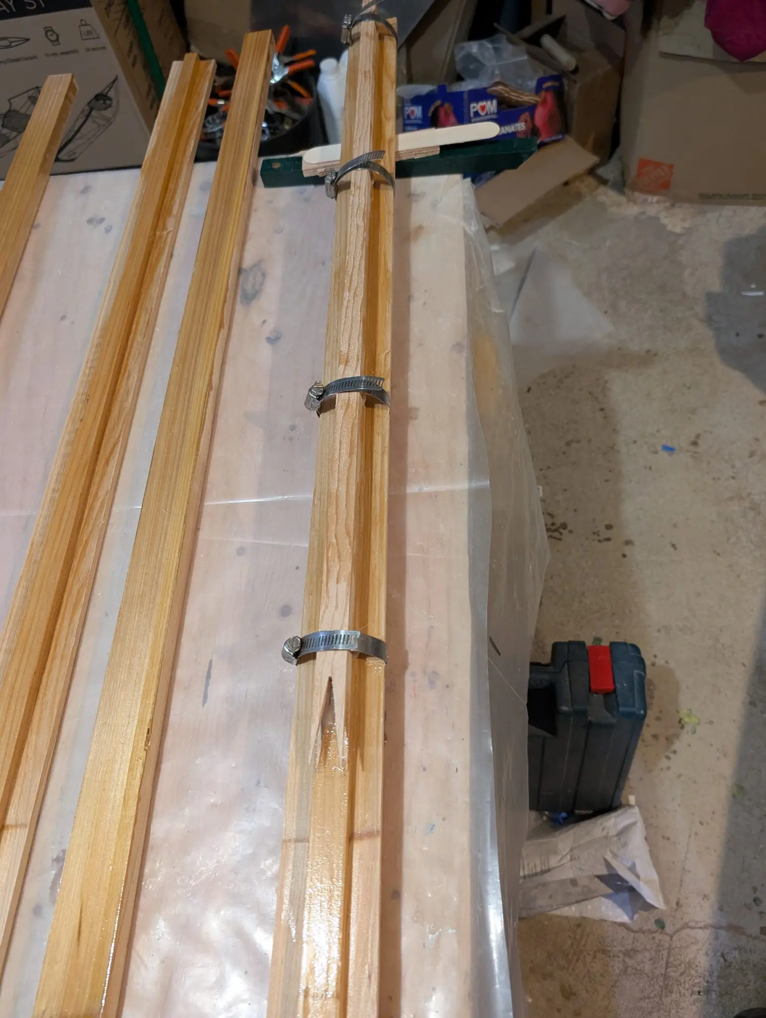
There is a yard and a boom for the Guider. The sail is laced to the yard but is loose-footed at the boom. Both spars are solid and built from glued pieces of solid wood; in my case, cypress supplied with the kit. The tapers for each were marked with full-size templates supplied by CLC and then cut with a bandsaw. After cutting the tapers into the blanks, the final profiles were worked in with hand planes. I owe much of the success of spar building (and many other things) to a good woodworking friend who has the gear and expertise. In exchange, I take him sailing. I think it's a win-win situation.
Laminating the blanks for the spars
The square blanks are planed flat on all four faces
The tapers are marked with templates (not shown), and then final shaping is done with handplanes and sandpaper
Just finished yard and boom (paint and rigging to be added later; watch this space)
Shaped spar and yard, with mast blank, sitting with the deck, awaiting more work.
Photo 1 Photo 2 Photo 3 Photo 4 Photo 5 Photo 6
18 Jan 2025Interior & Cockpit
Springing in the deck carlins
The deck carlins are long battens sprung into notches in the frame inboard of the shear clamps. They support the inner part of the main deck. I had a little setback doing this because I didn't open up one of the frame notches sufficiently. This created an unfair curve in the port carlin and created a stress point in the timber. It snapped right at that stress point. I re-scarfed the carlin, opened the notch a bit, and reinstalled it successfully.
Photo 1 Photo 2 Photo 3
5 Feb 2025Interior & Cockpit
Shaping sheer plank and deck carlin
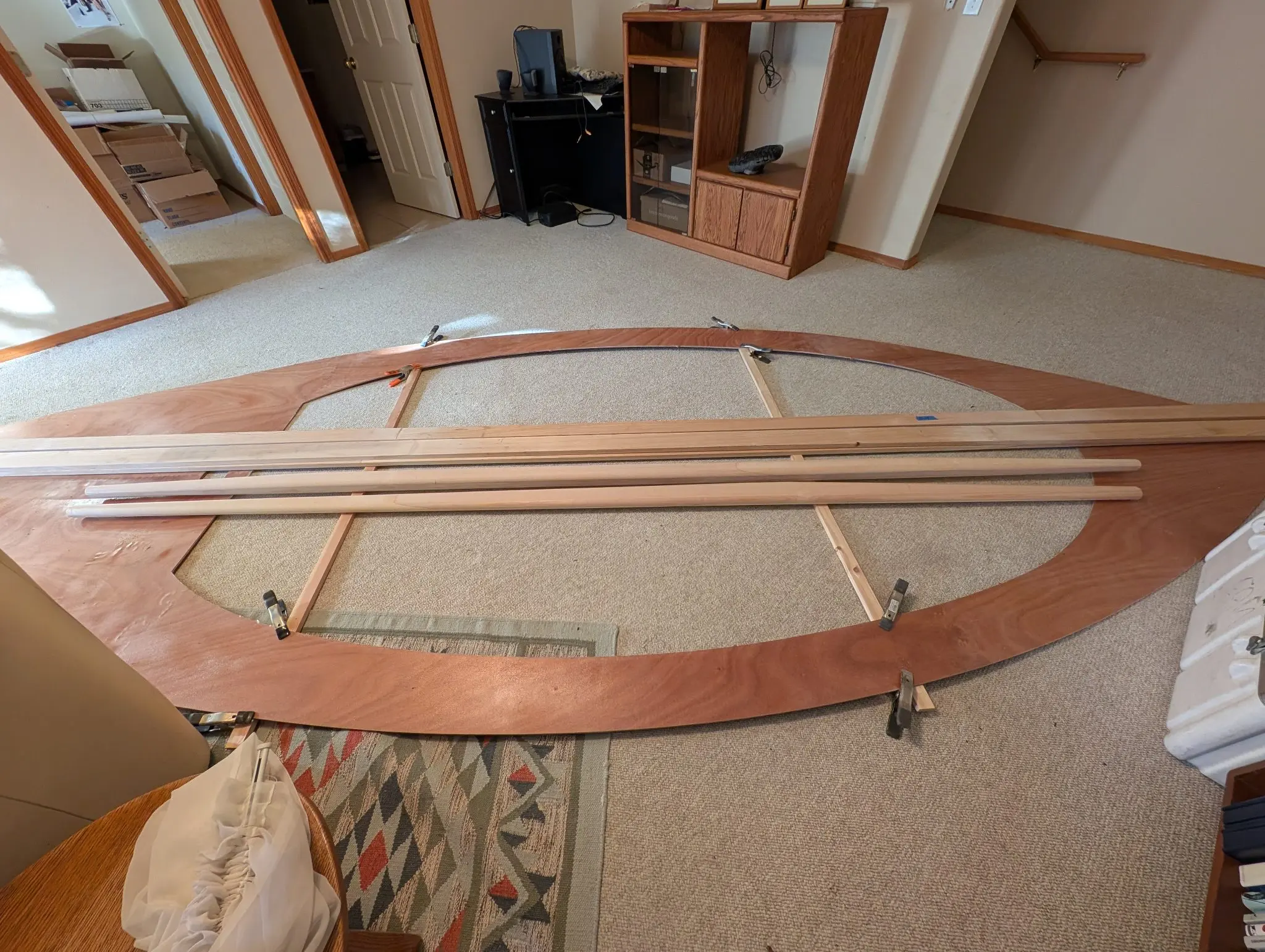
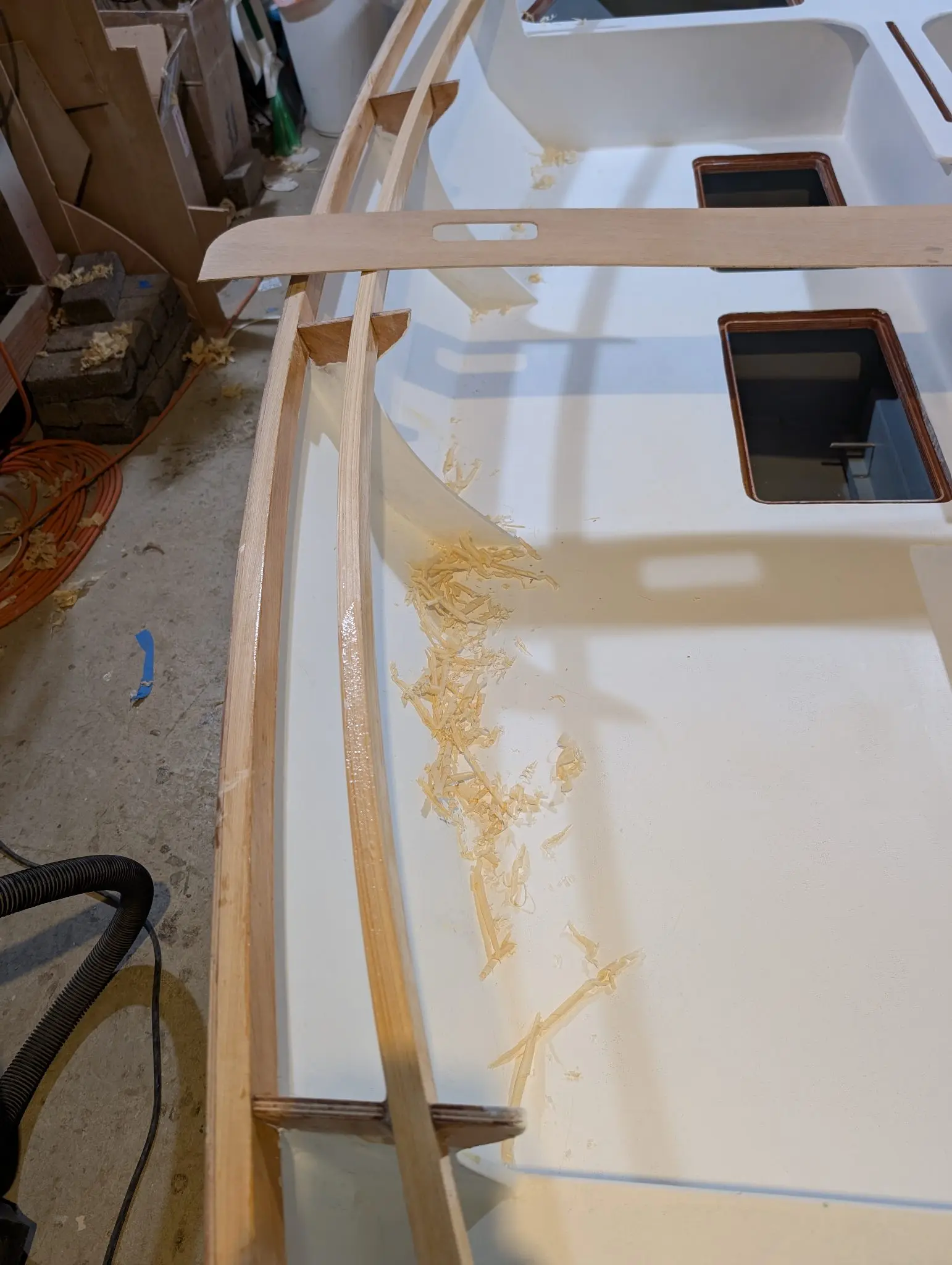
In addition to rocker fore and aft, the deck also has camber athwartship. In order to get a tight fit of the main deck on the sheer plank and deck carlin, they have to be planed so the deck sits flat on them. CLC provides a full-width template to help with this. This is a time-consuming process, but it pays to proceed carefully and thoughtfully here.
The template for shaping the sheer plank is shown at the top
I also found sticking sandpaper on long sanding boards to be very useful for small adjustment.
Photo 1 Photo 2
6 Feb 2025Interior & Cockpit
Interior paint
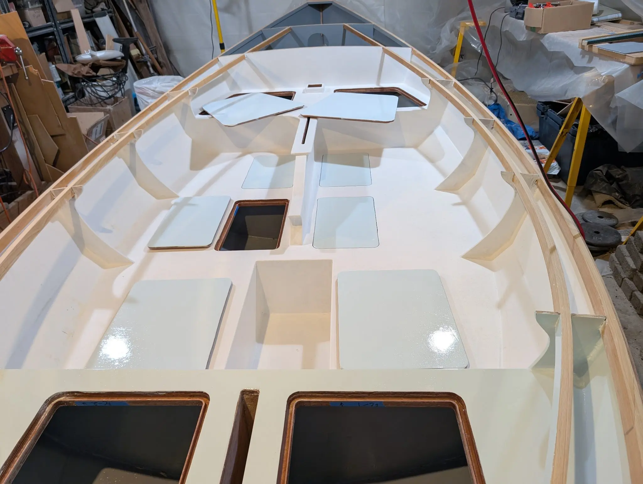
From about Jan 18 to Feb 6 was spent painting the interior decks, hatches, and the inside of the hull in the cockpit. Painting is tedious, but it pays to be careful. I used peel coat on all the surfaces when I glassed them, which gives a smooth surface at a macro level but leaves a fine matte texture behind that persists unless you actually fair the surface. Consequently, I didn't really get a glossy, mirror finish on the paint. I think it looks ok though. Everything was primed with two coats of Interlux Top-Kote Plus, and then three coats of Interlux Toplac Plus. I generally liked both products and found them pretty forgiving. The Toplac final coats were a shade called Icy Blue, which really seems white to me, but when it's right up against a true white, it does have a bluish tint.
Photo 1 Photo 2 Photo 3 Photo 4 Photo 5
7 Mar 2025Hull Exterior
Building the rudder blade
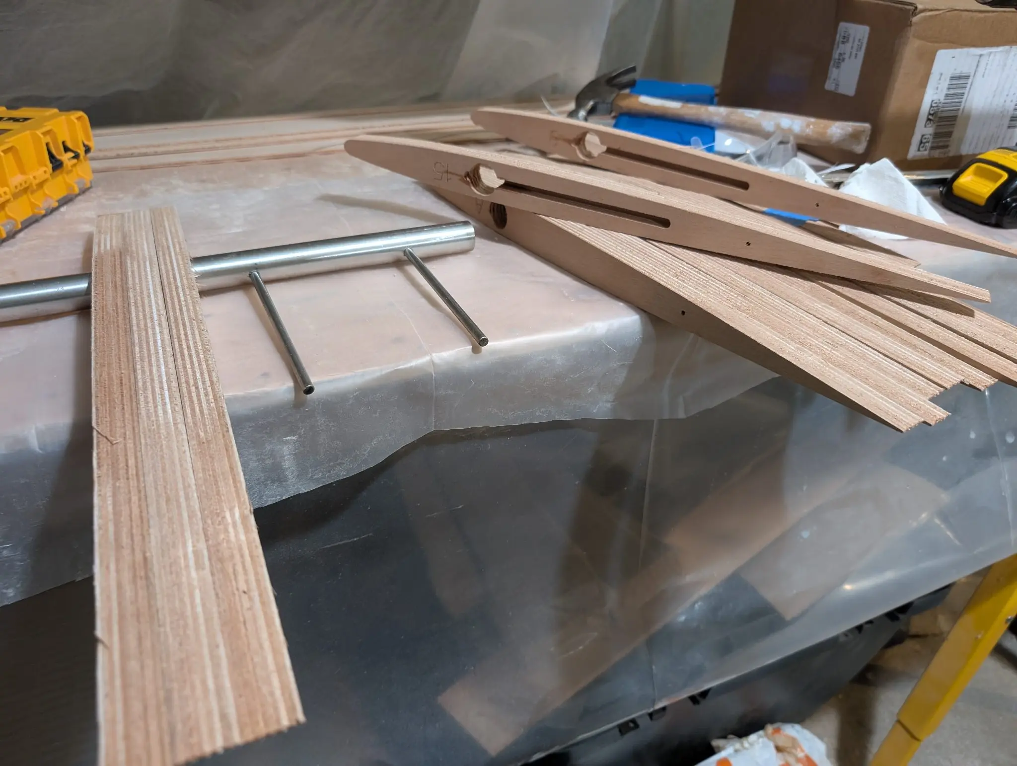
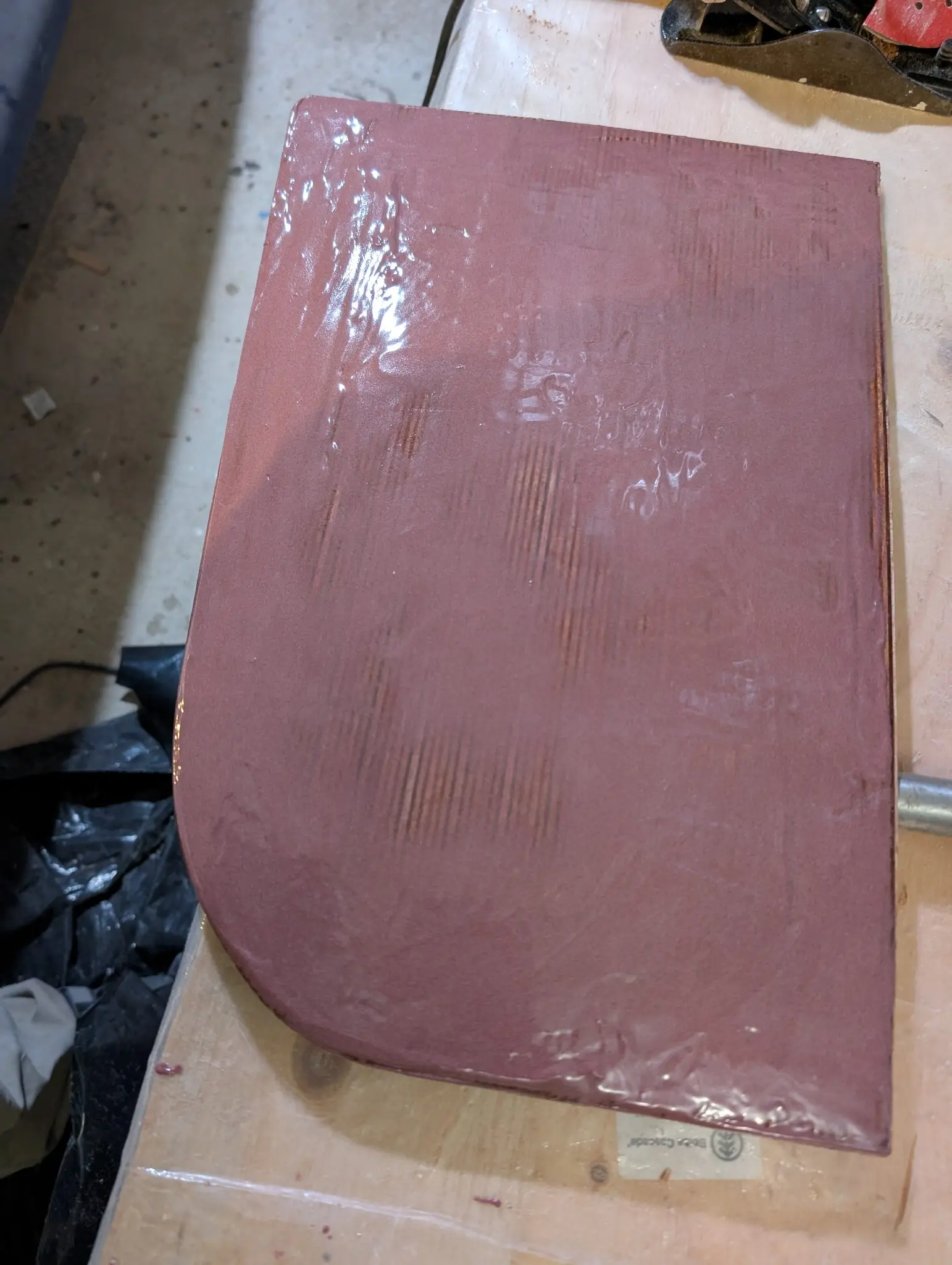
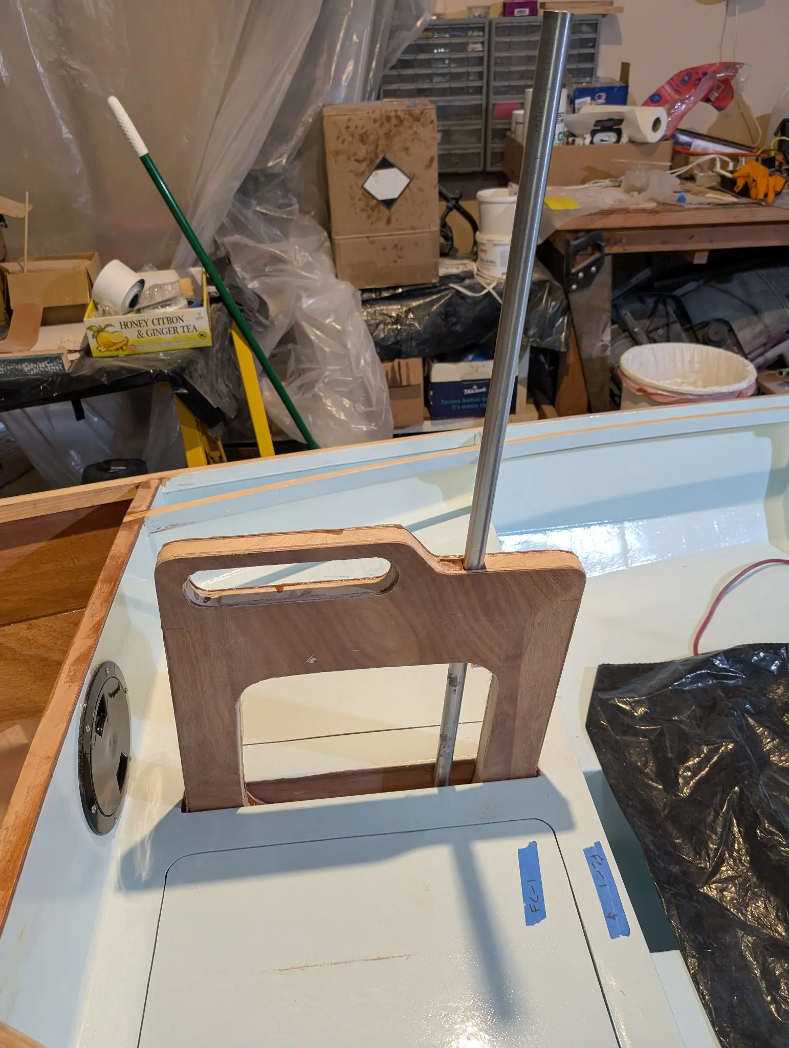
The rudder blade is built of stacking foil shapes cut from marine plywood. A stainless steel tube for a rudder post slides through the top foils. Two small stainless steel rods are inserted through the rudder post and fit into slots in two of the foils to handle the torque from the blade. Small dowels are inserted into holes in the stack of foils to keep everything aligned.
Here you can see the way the foils stack on the rudder post. Also visible are the rods that translate the torque from the post to the blade, and the slots into which those rods fit.
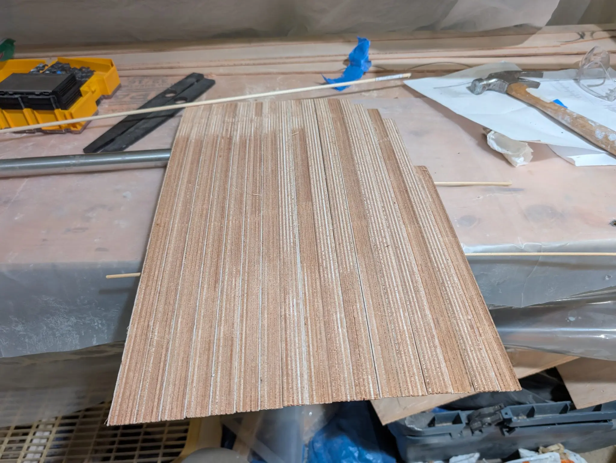
The rudder blade stacked up dry. You can see the small wooden dowels that keep everything aligned.
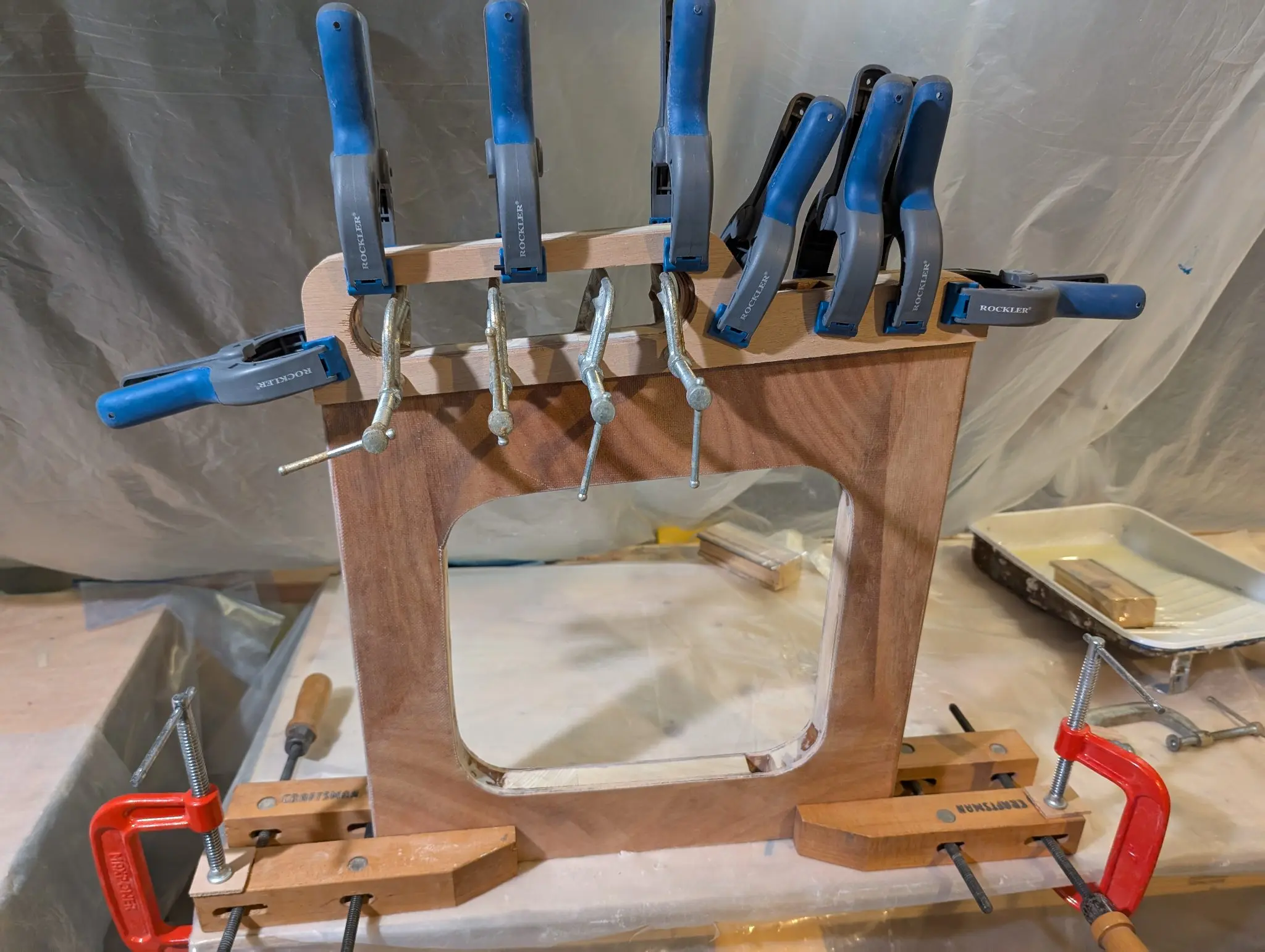
All dry-fitted with clamps in place. It's always useful to dry-fit things and practice the procedure before you get epoxy involved.
All glued up and clamped
Rough rudder blade, glued and cured.
The blade cut to shape, sanded and coated with epoxy
The blade must be smooth and fair, so I have put medium-density fairing compound on it. It took several applications with sanding to get it satisfactorily smooth. The photo does not show its final state.
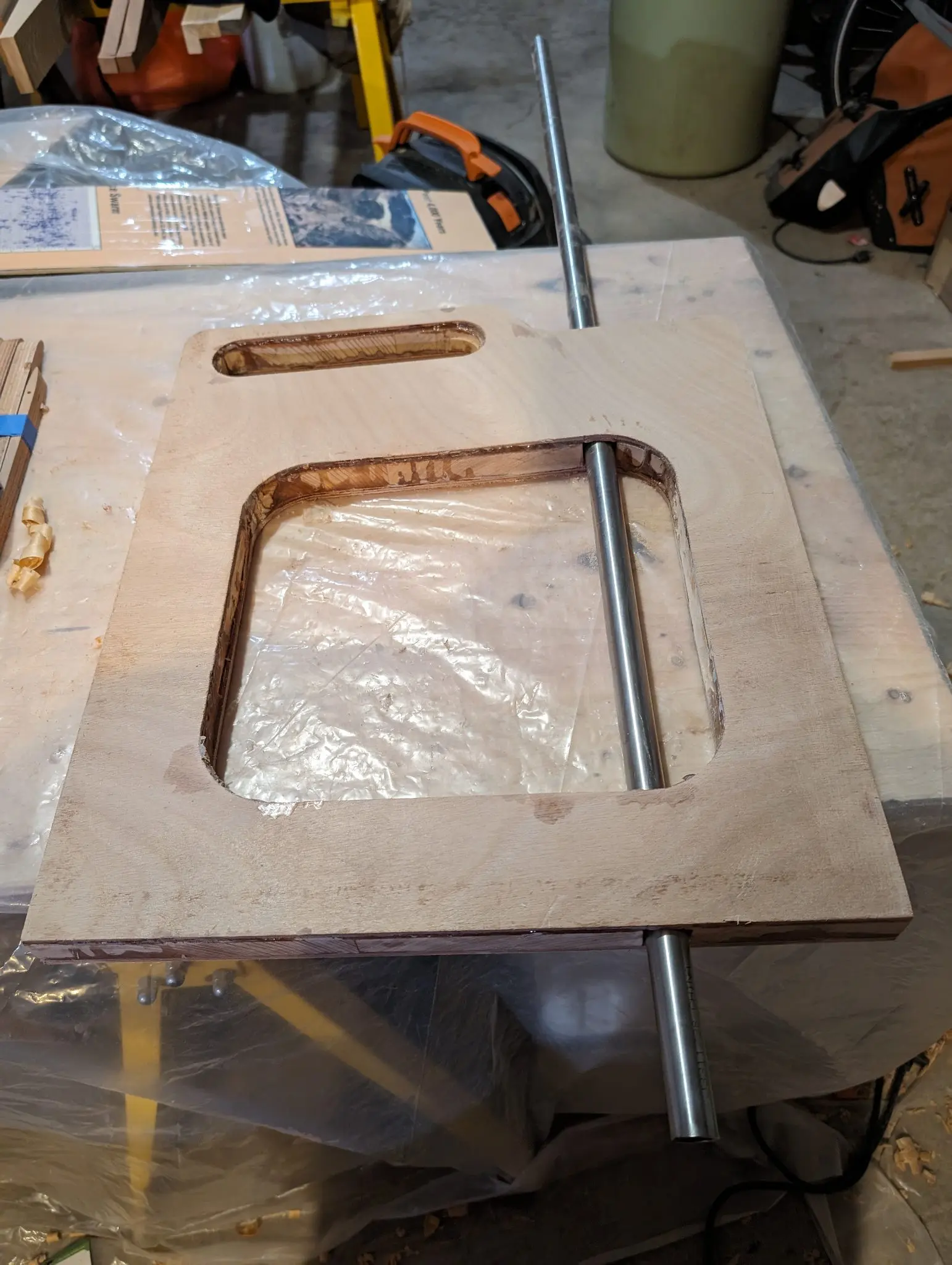
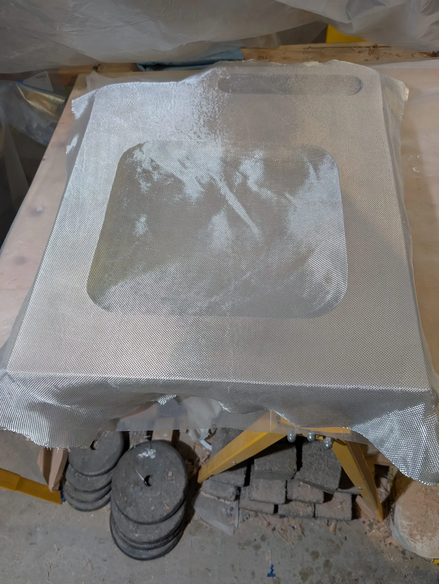
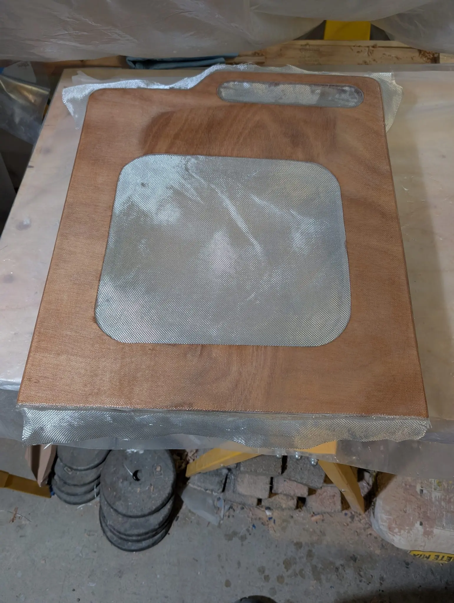
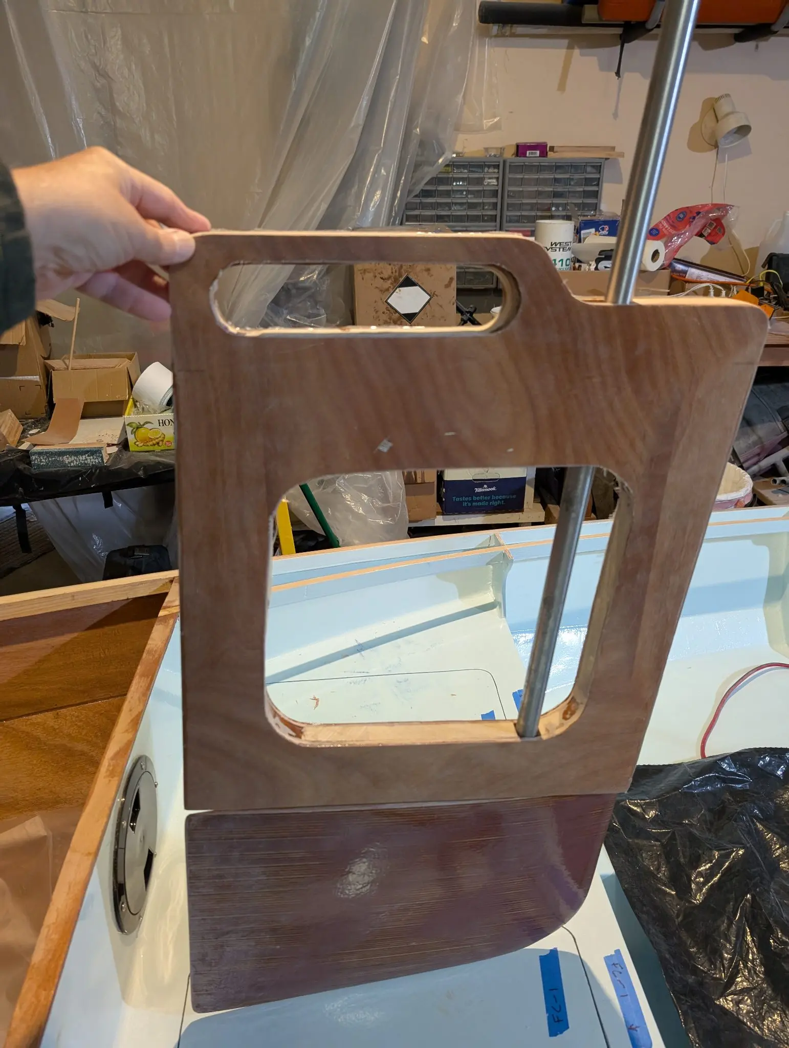
With the rudder blade done, I returned to work on the rudder cassette. Both sides are glassed and the rudder post and blade are inserted to check the fit. Then the cheeks, which sit on the shoulders of the rudder slot, are glued on.
Fiberglass cloth going on
cloth wet out and curing.
Rudder post and blade fitted to the cassette
Rudder assembly sitting in its slot in the deck/hull
Cssette cheeks being glued to the cassette.
It fits!
Photo 1 Photo 2 Photo 3 Photo 4 Photo 5 Photo 6
Chapter 10
Deck & Coamings
Decking, hatches, coamings, cockpit rim.
5 daysfrom March 2025
30 Mar 2025Deck & Coamings
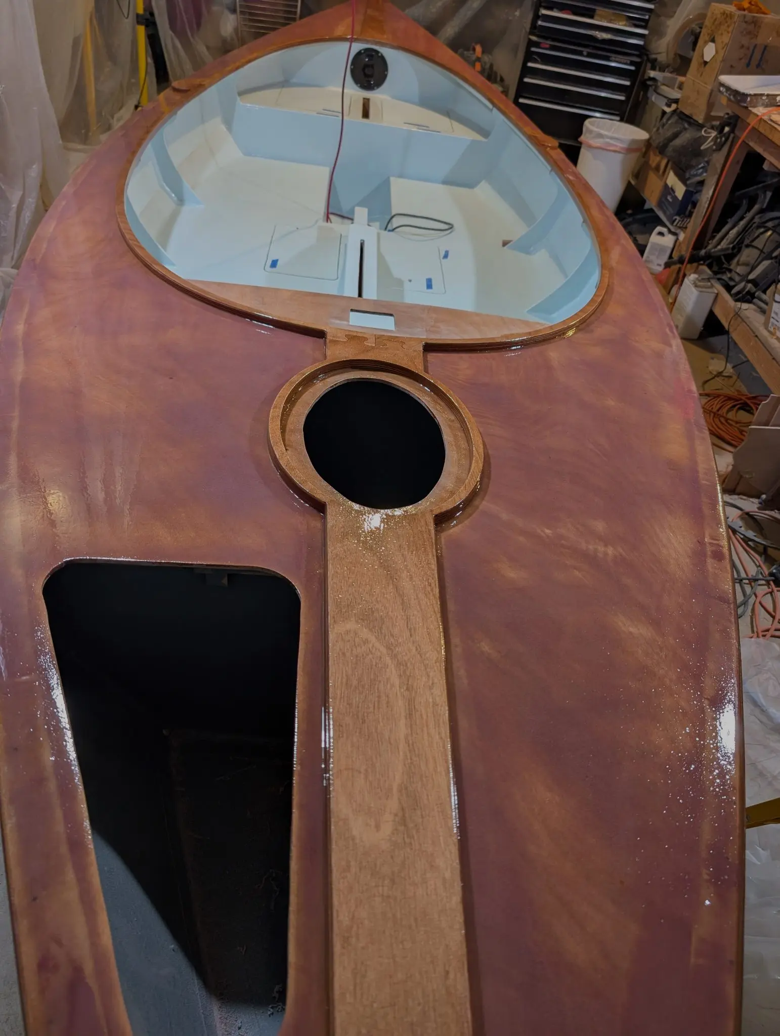
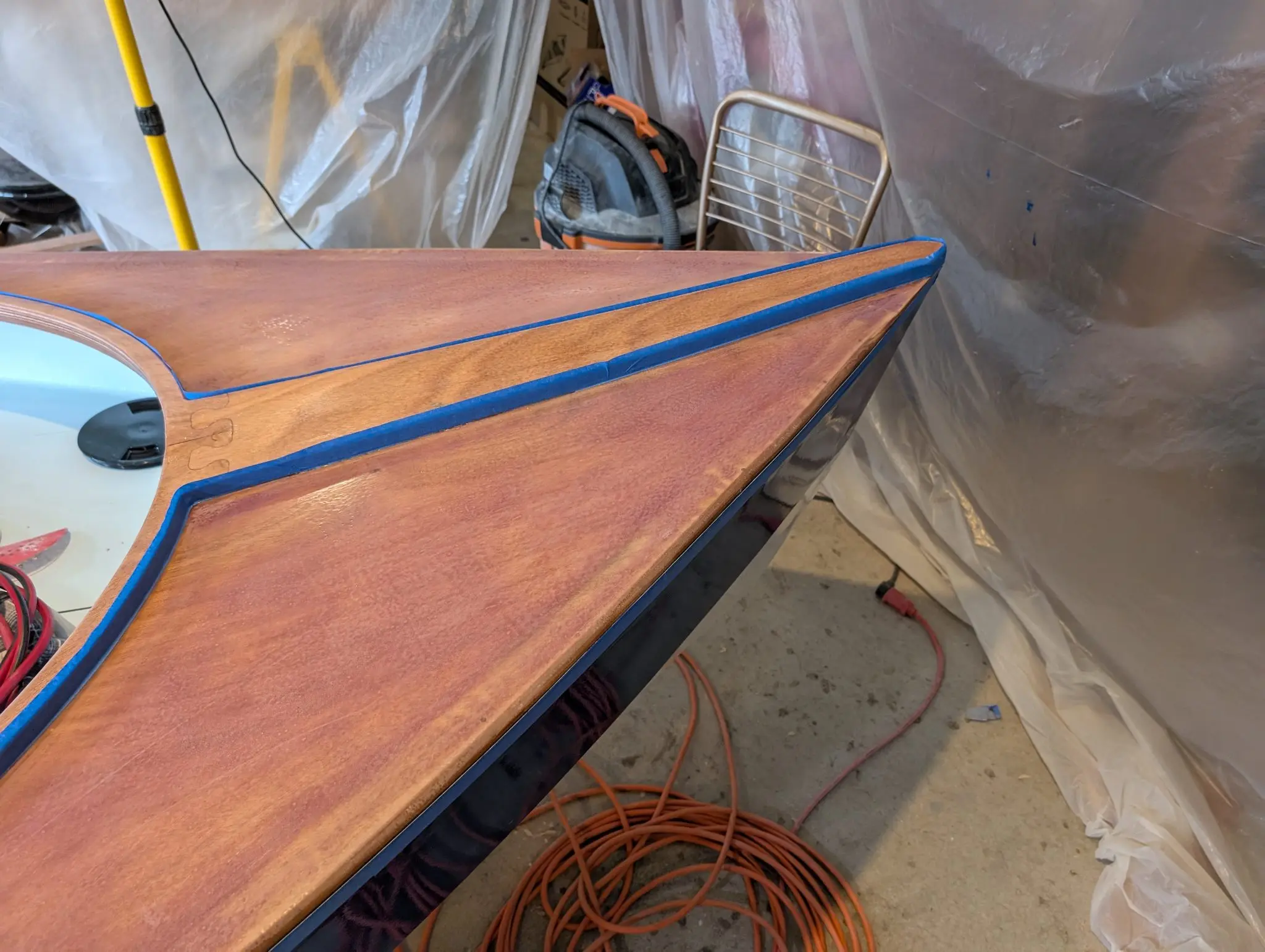
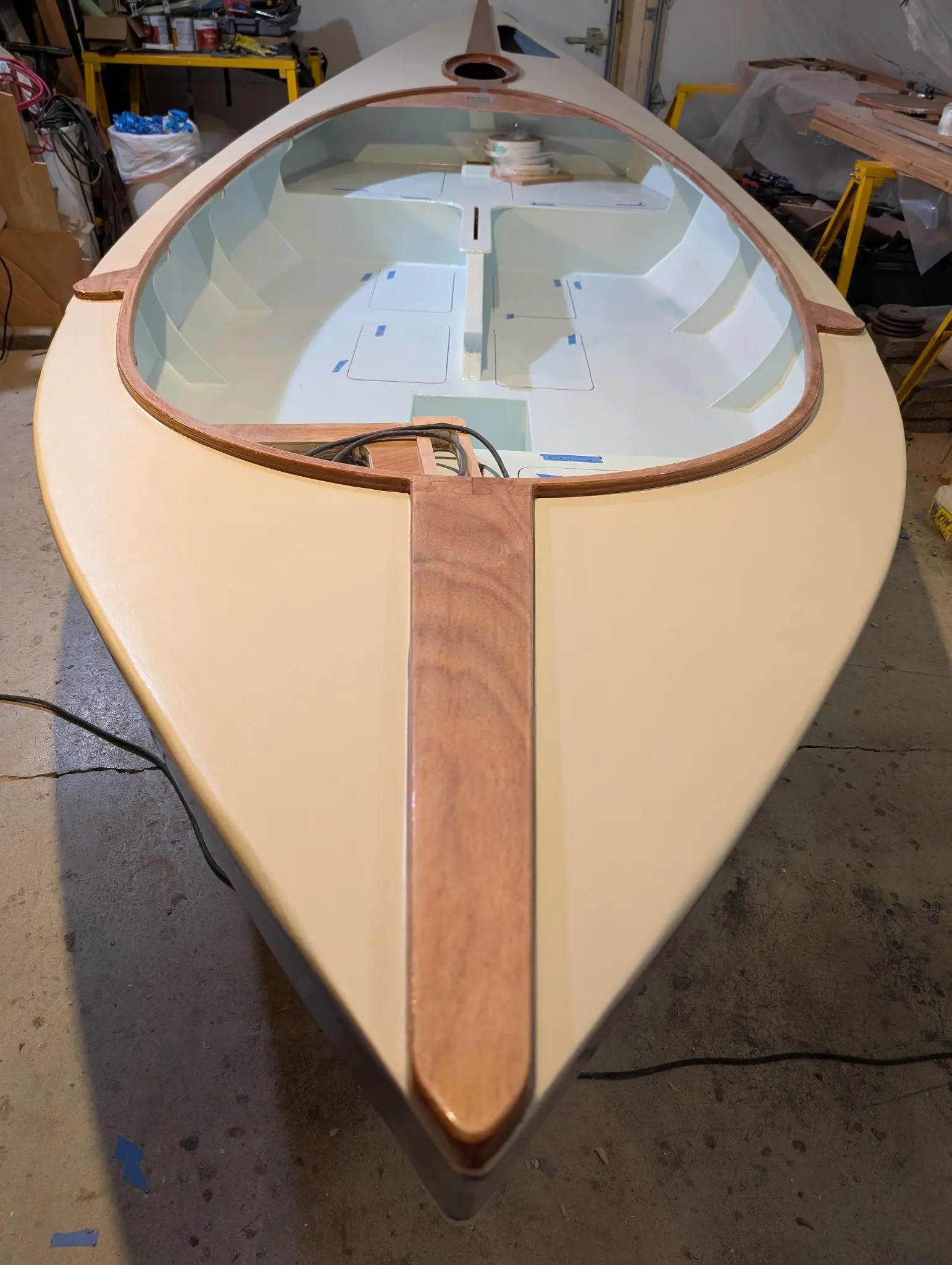
Install cockpit coaming and king plank
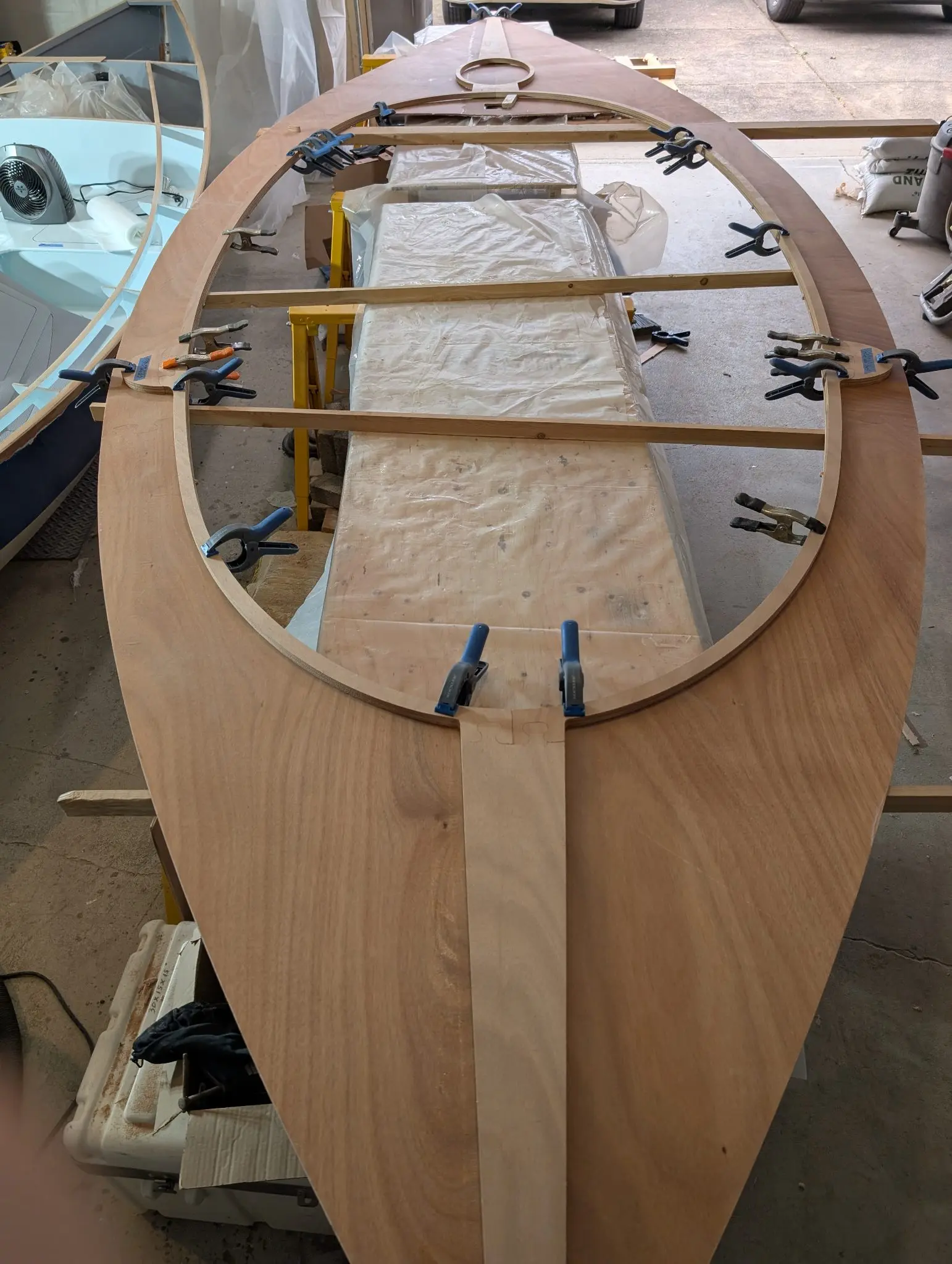
The next sequence was gluing the coaming and king plank assembly to the main deck. This was a big and quite difficult job.
Dry fitting with a few clamps. I didn't really have a big enough job table, so I used 1 x 2" strapping to support everything.
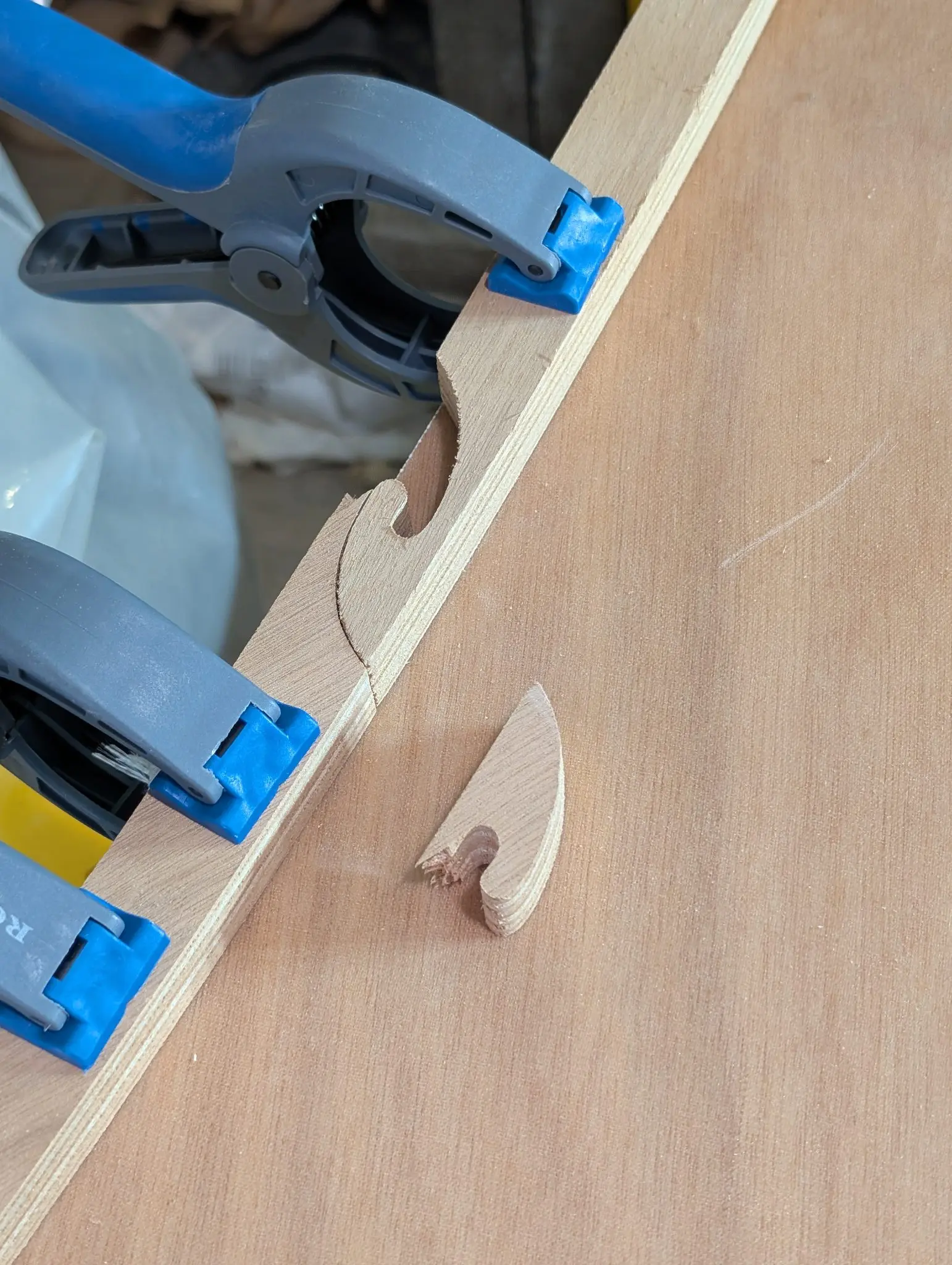
The finger joints on the coaming are quite delicate, and I broke one. I just glued it all back together, which seemed to work just fine.
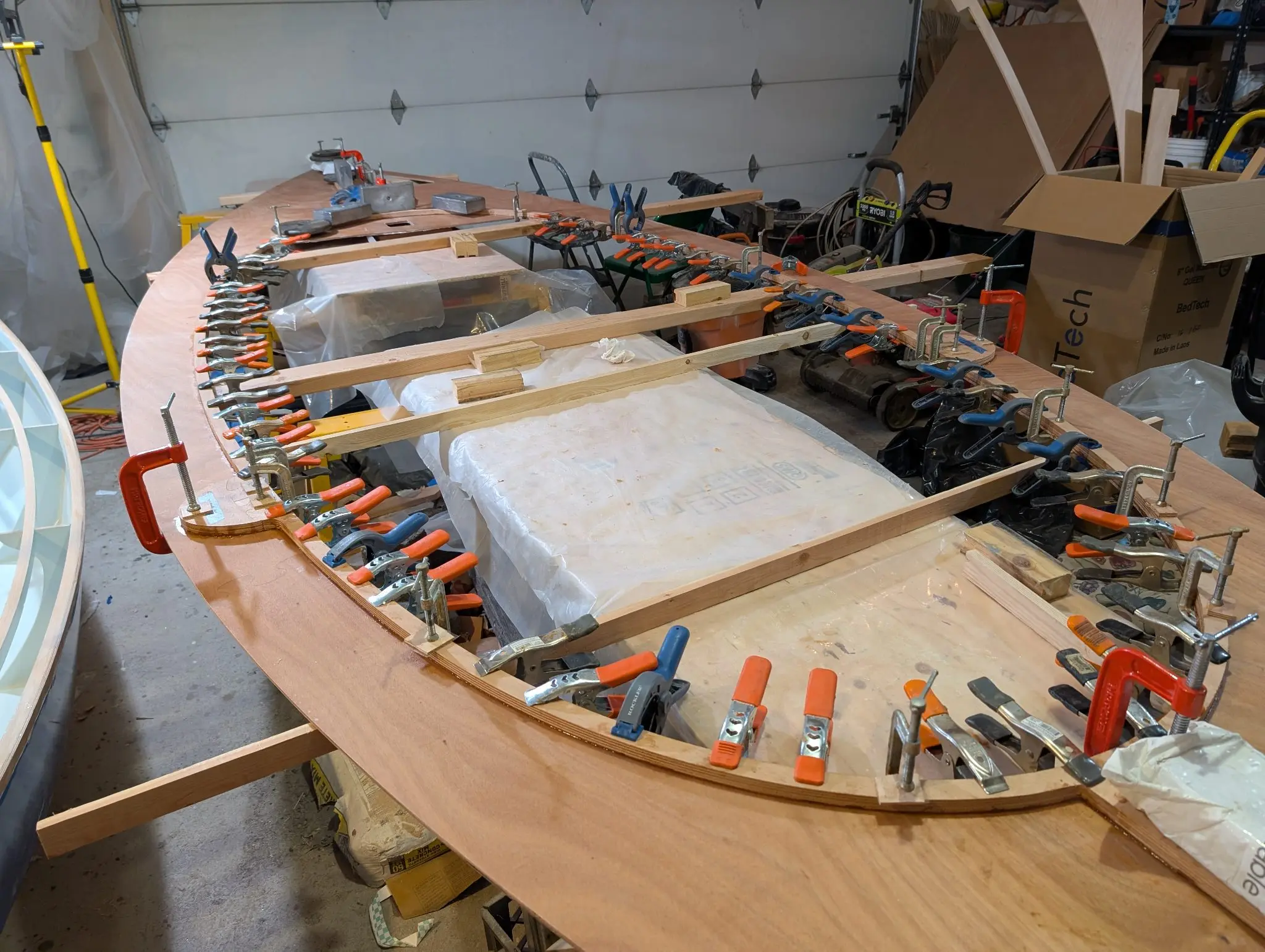
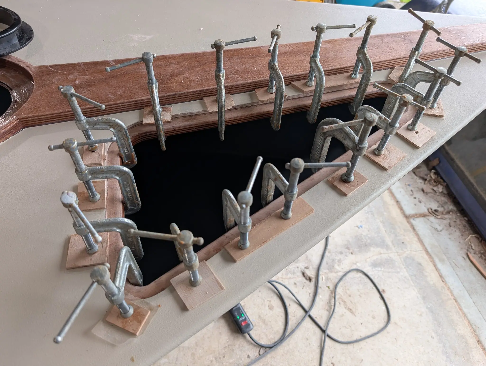
Clamps and more clamps are required.
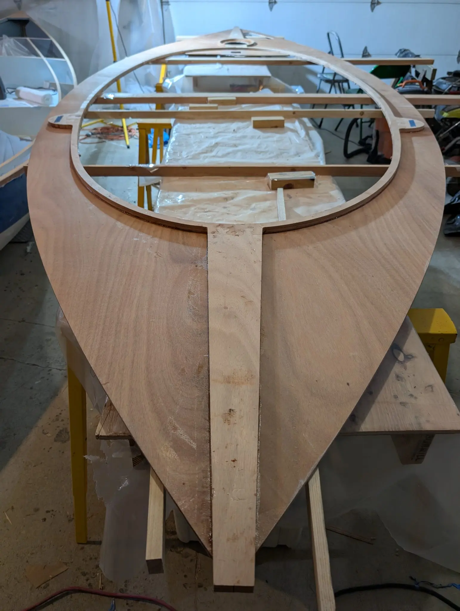
Cured and clamps removed
The deck was set on the hull to check fit. It really didn't fit perfectly. There are so many places in the whole build where things might be off a bit. It's going to be fine.
Photo 1 Photo 2 Photo 3 Photo 4 Photo 5
5 Apr 2025Deck & Coamings
Problems with deck fit and their solutions
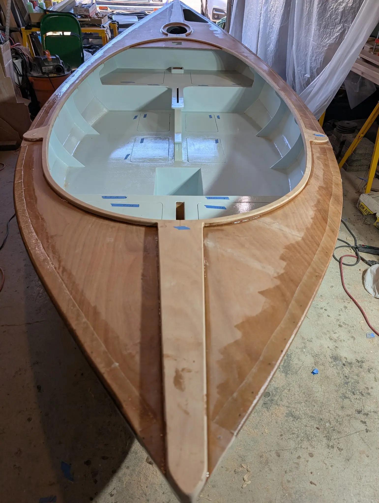
When I put the main deck on the hull, it was immediately clear it didn't fit well. The frames impose a significant camber athwartship. Having glued the coaming and king plank while it was off the boat meant the deck was essentially flat along that axis. I found I could remind it of its duty with a lot of weight and clamps to force it into place. The second problem was that somehow frames 1 (bow) and 7 (stern) were not sitting up enough. There was a 3/8" gap between the deck in frame in both places. The solution was to shim up each frame with a plywood strip to fill the gap. I used the CLC template to plane the shims to the approriate curve. I am not really sure what went wrong there but I assume I just didn't get the planks seated completely tight and so they stood proud of the frames? maybe?
Dry fitting the main deck to the hull.
With a LOT of weight and clamps, I was able to get the deck to conform to the camber of the frames
The breasthooks at bow and stern both needed to be shaved down to get the deck to sit flush on them.
4, 5. Somehow, frames 1 and 7 were too low and had to be shimmed up. Then I planed them down to conform to the camber template CLC provided
Photo 1 Photo 2 Photo 3 Photo 4 Photo 5
12 Apr 2025Deck & Coamings
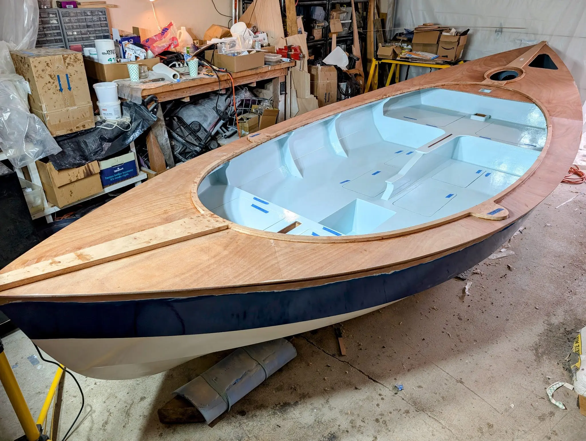
The main deck is on, permanently
After fretting about alignment, fixing fit problems, and a lot of prep work, I finally glued on the main deck. When finished, there are no mechanical fasteners between the deck and the hull; you have to get it glued down securely in one take. There are no second chances.
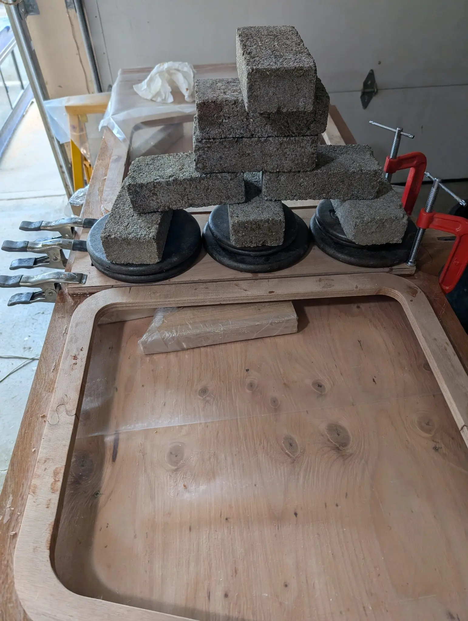
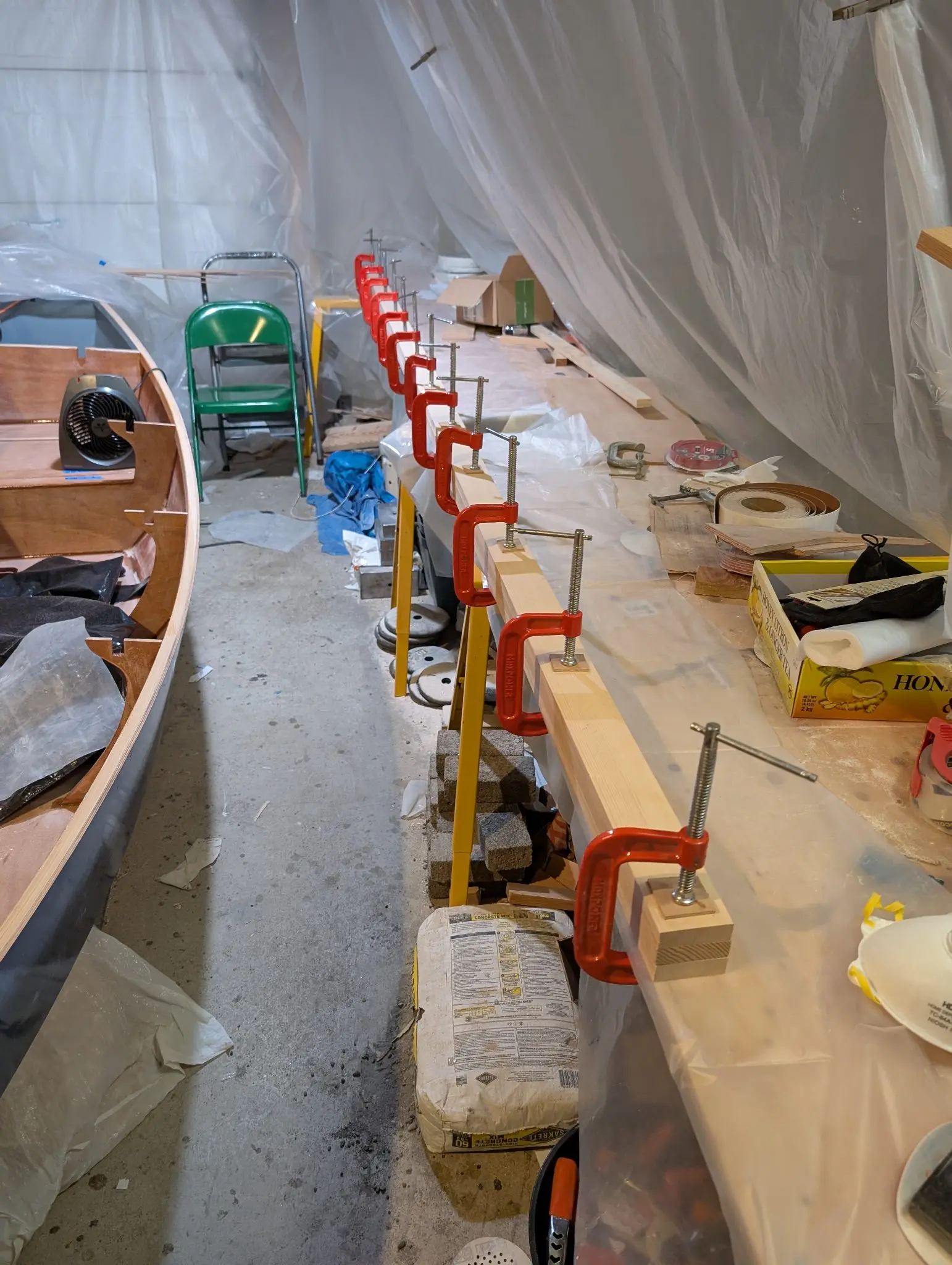
It takes a lot of weight to get the flat deck pressed down onto the cambered supports. I used fender washers and wood screws to pull it down to the shear planks. CLC provides a gauge for locating these accurately. I couldn't locate the interior supports accurately enough, so there I relied on weight, lots of weight.
The inside clamps are pulling the deck down to the deck carlins
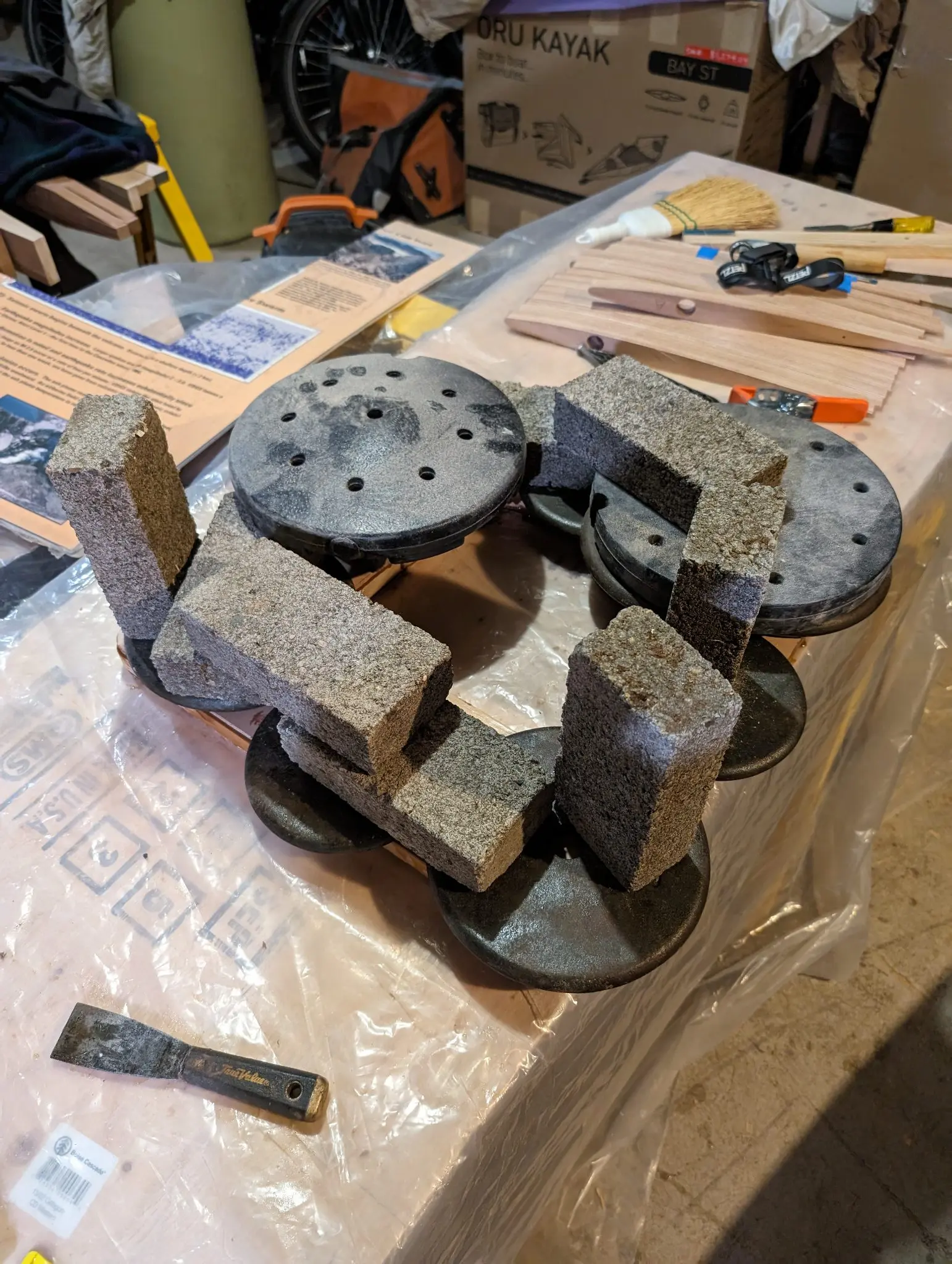
I used lead bricks, cast iron weights, and concrete bricks to make the deck behave. It seems to have worked!
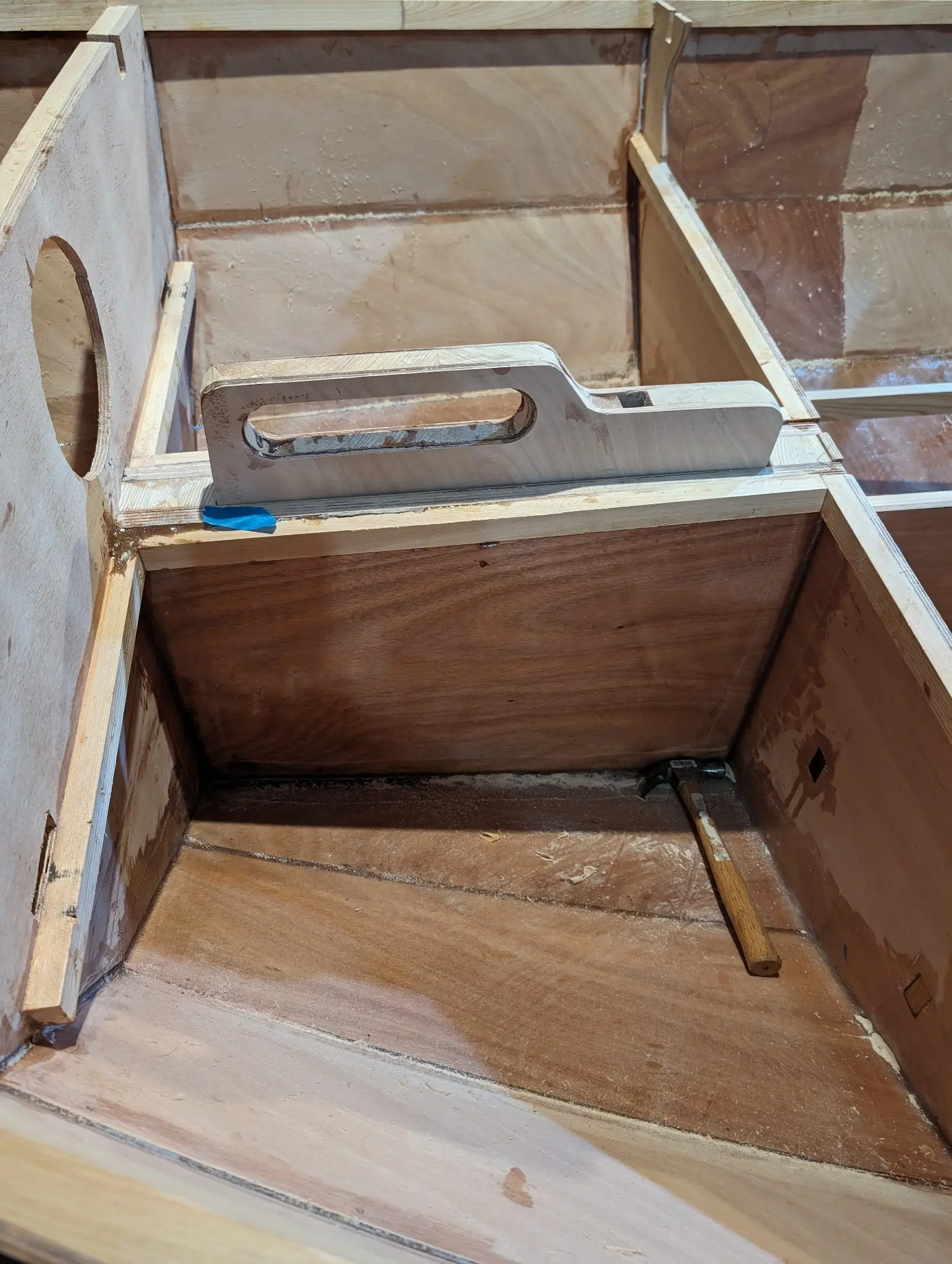
The carlins, shear planks, frames, and breasthooks got generous beads of thickened epoxy on their tops so I sheeted the interior in case some wanted to drip down.
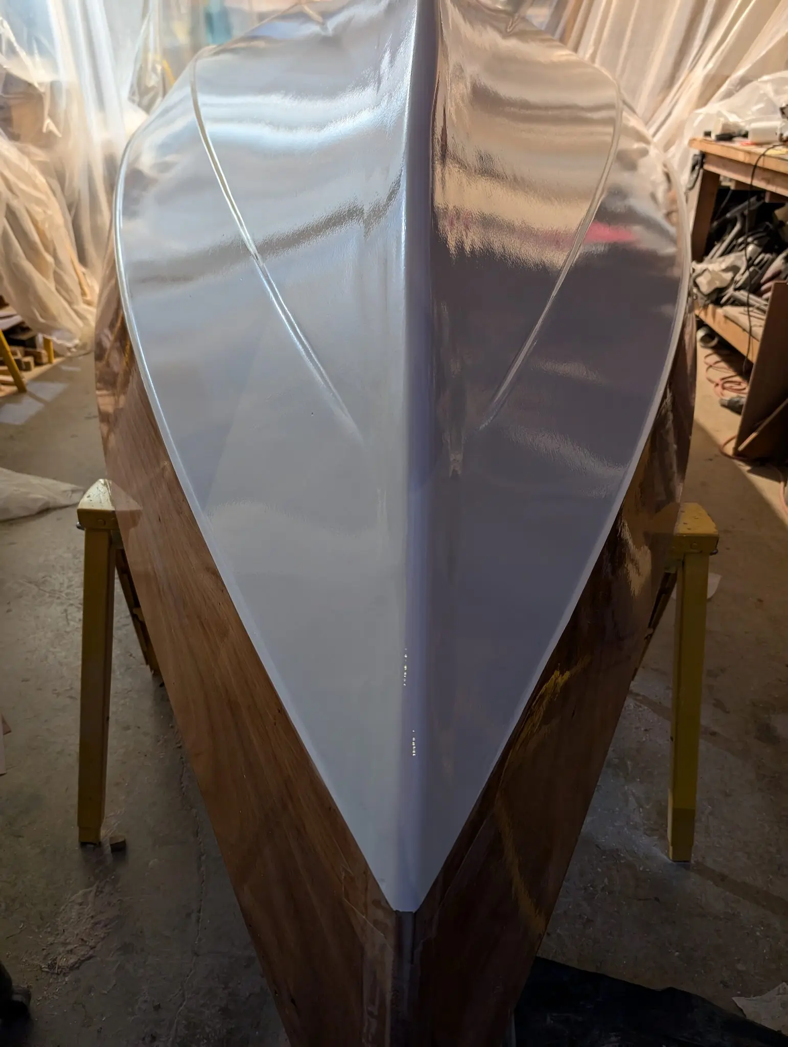
After removing all the clamps and fasteners, I ran my router on the edge with a flush cut bit
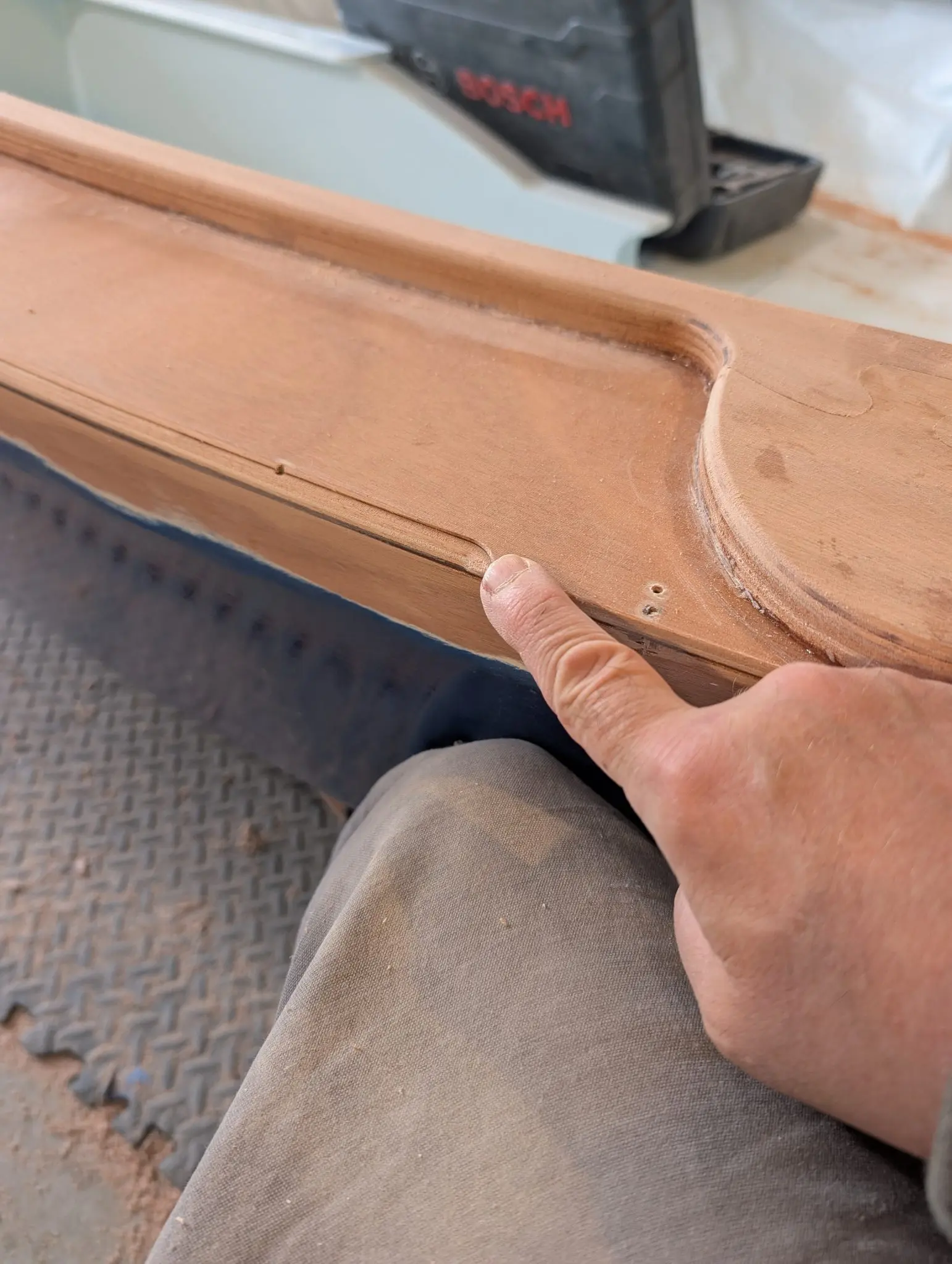
Since I am going to reinforce the Devil's seam I also ran a round over bit along the edges so the tape would lie down properly. I couldn't use the router too near the oarlock pads. I just left it sharp and didn't tape there.
Photo 1 Photo 2 Photo 3 Photo 4 Photo 5 Photo 6
15 Apr 2025Interior & Cockpit
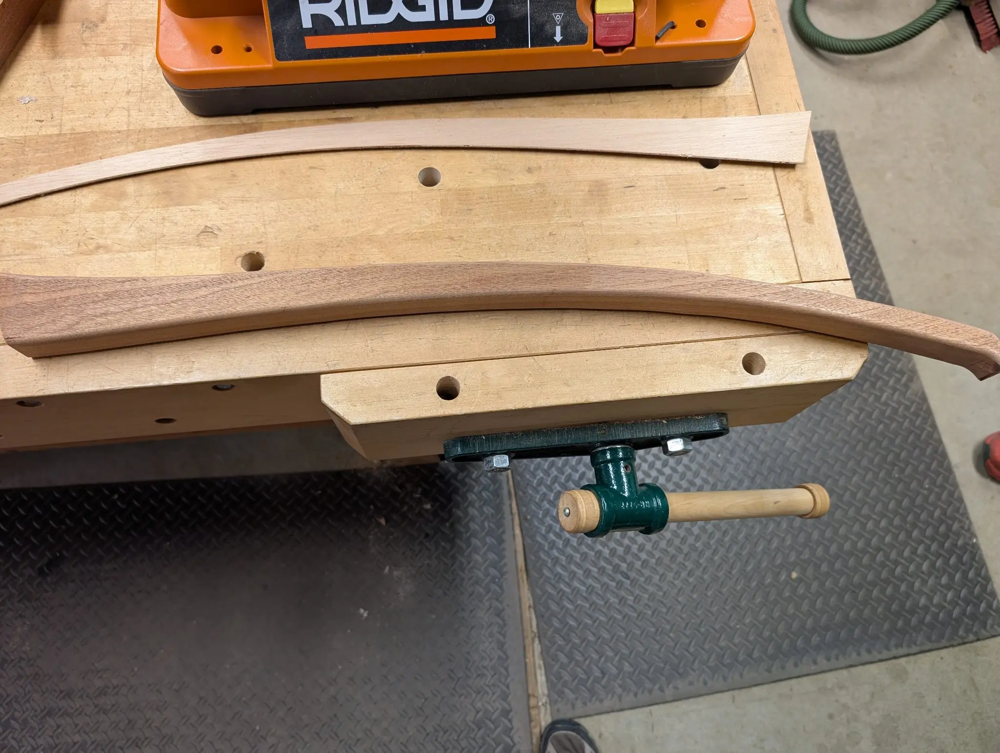
Making the tiller
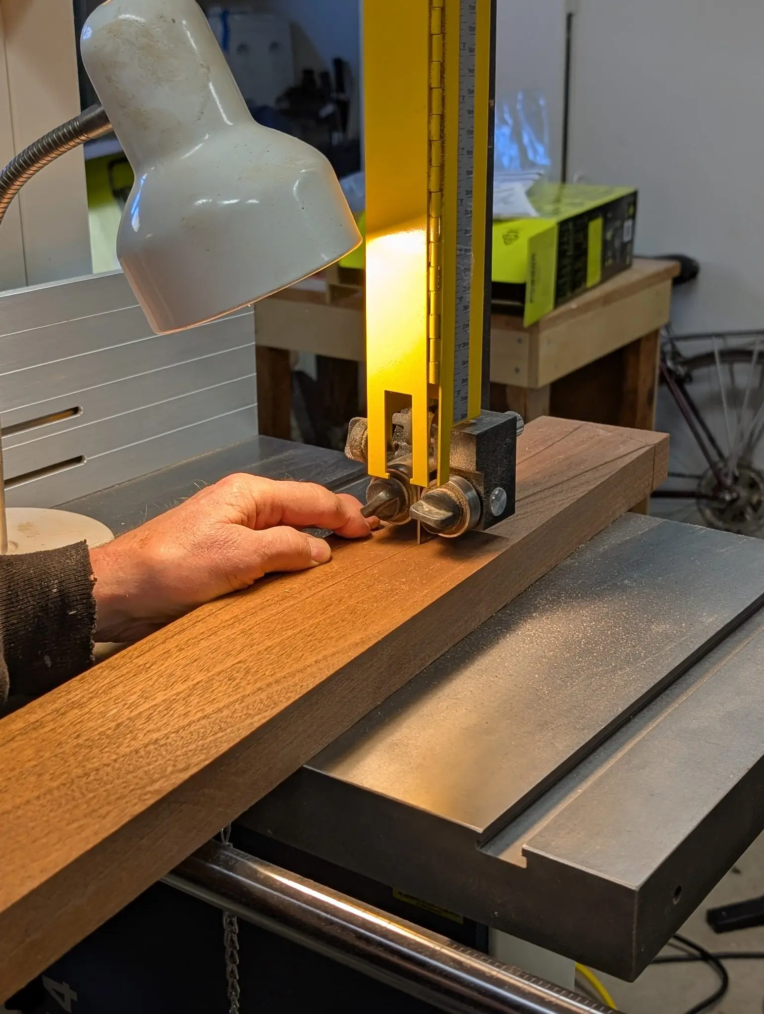
CLC provides a template for the tiller shape. I cut it out with a bandsaw from a solid piece of Mahoganoid wood supplied with the kit. The edges were rounded over with a router, and then the piece was finished with an oscillating belt sander to remove tool marks.
Photo 1 Photo 2 Photo 3
4 May 2025Deck & Coamings
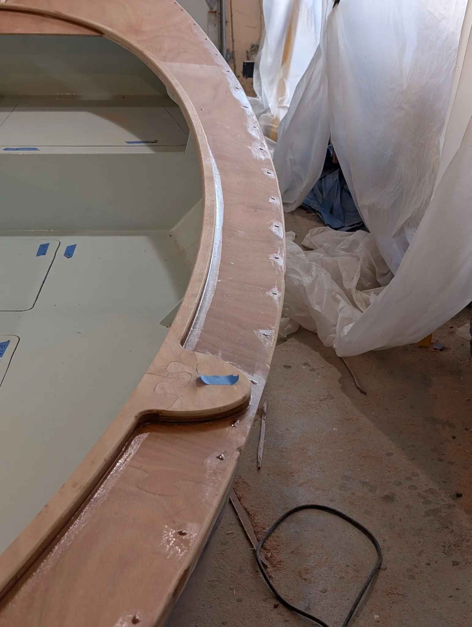
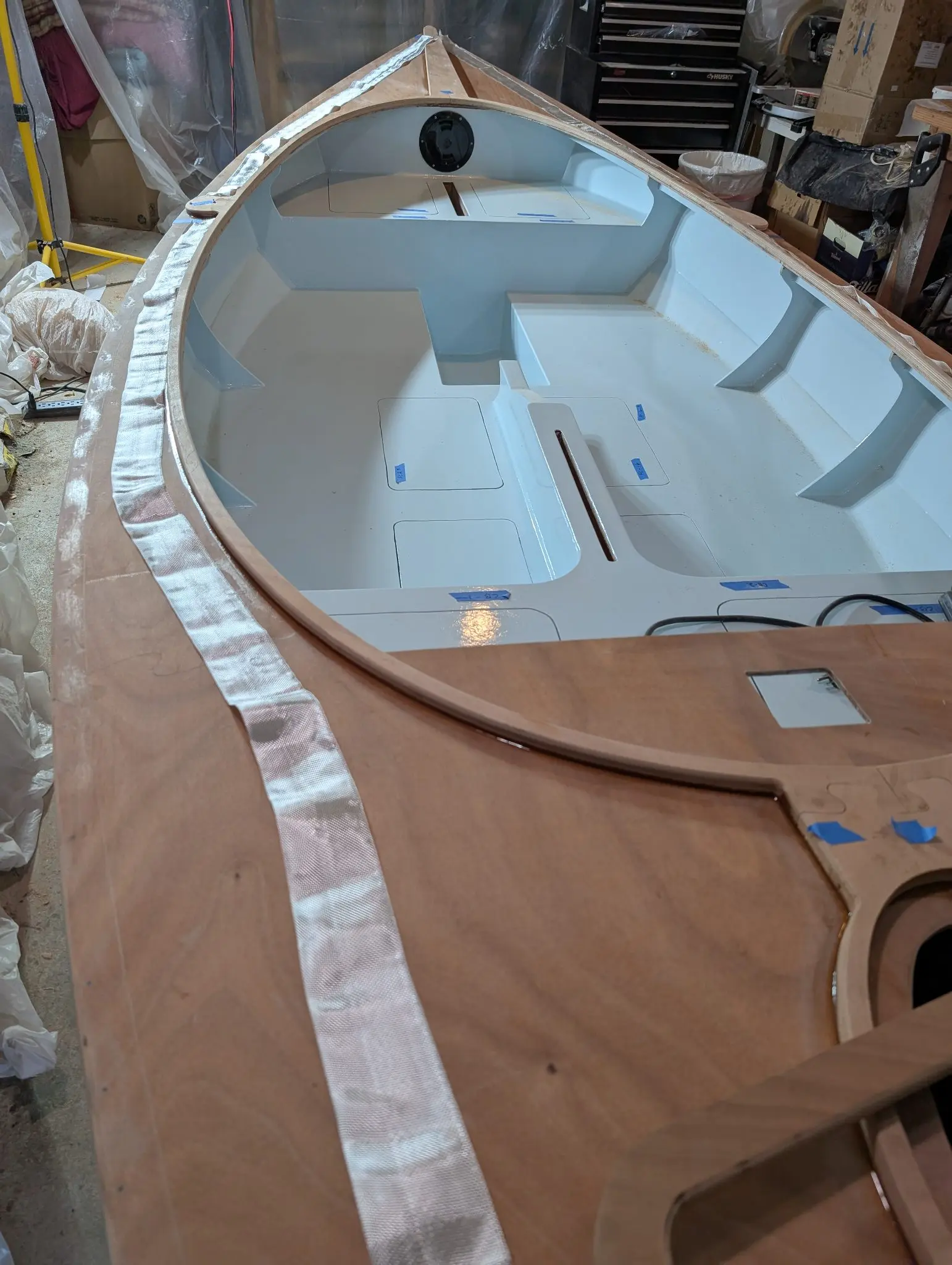
Now that the deck is glued onto the boat, I need to reinforce the Devil's seam with FG tape.
Fill all the screw holes that had fender washers to clamp the deck down, sand them smooth.
Lay out the tape and practice the glue up steps. I decided NOT to cut off the tape selvages, dooming myself to more sanding. I just don't do well with loose tape edges. They always seem to end up fraying and making a nuisance of themselves.
Tape is down and curing.
I want this to be a very smooth deck so I laid down a thick coat of medium density filler.
Filler sanded, view from rear
filler sanded, view of deck
Rather than fairing the tape into the hull, I just feathered it in by sanding
A final coat of epoxy over the fairing layer. This is probably unnecessary but I didn't want any water to get into the fairing if the paint were to be gouged or something. Besides, I just love epoxy work....
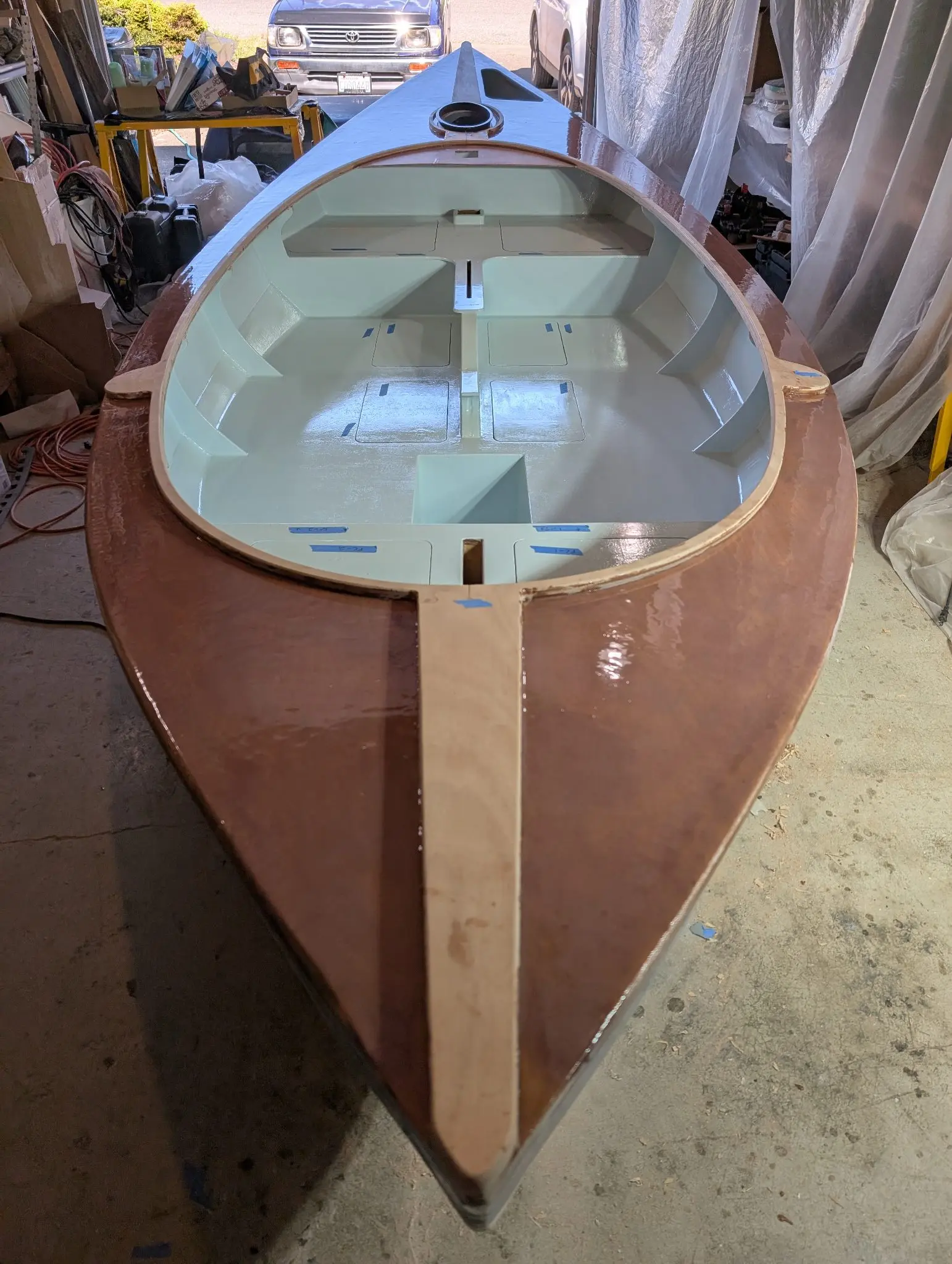
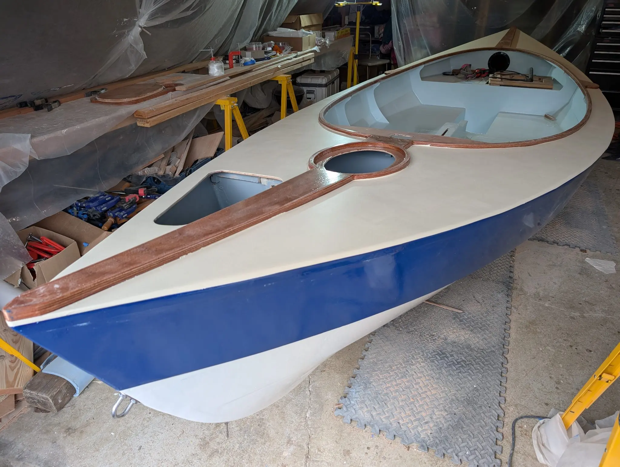
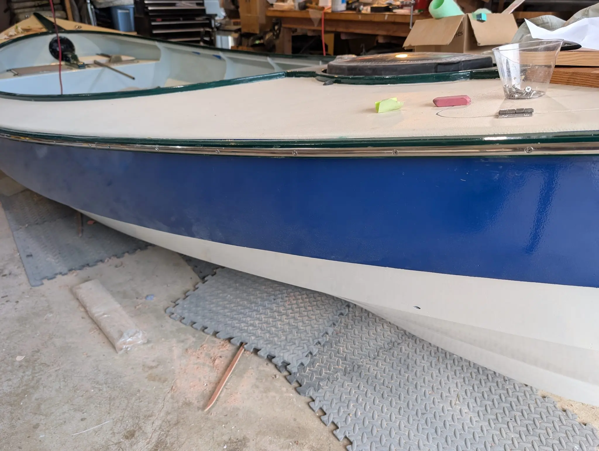
What followed was 2 weeks of painting work. Masking, priming, painting, second coat, touchup, removing the masking tape, more touchup etc. I am not going to take you through the agony in great detail. I use Interlux Interdeck non-slip paint in sandy beige for the deck. If I haven't said so before, I used Interlux Sapphire Blue for the shear strake and Mediterranean white for the rest.
Electrical, plumbing, fuel, steering, pumps, nav lights.
1 dayfrom May 2025
19 May 2025Systems
a break from painting
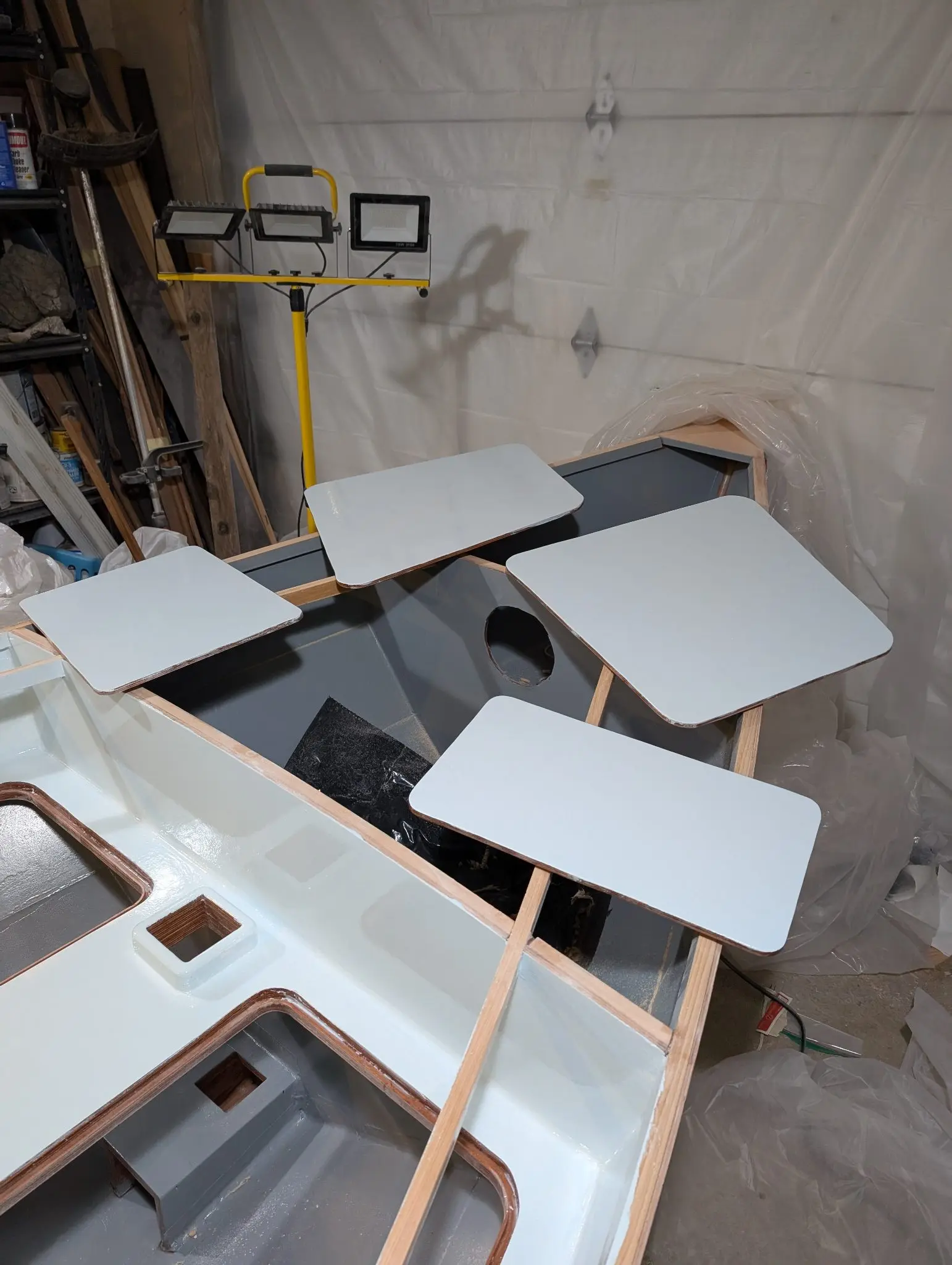
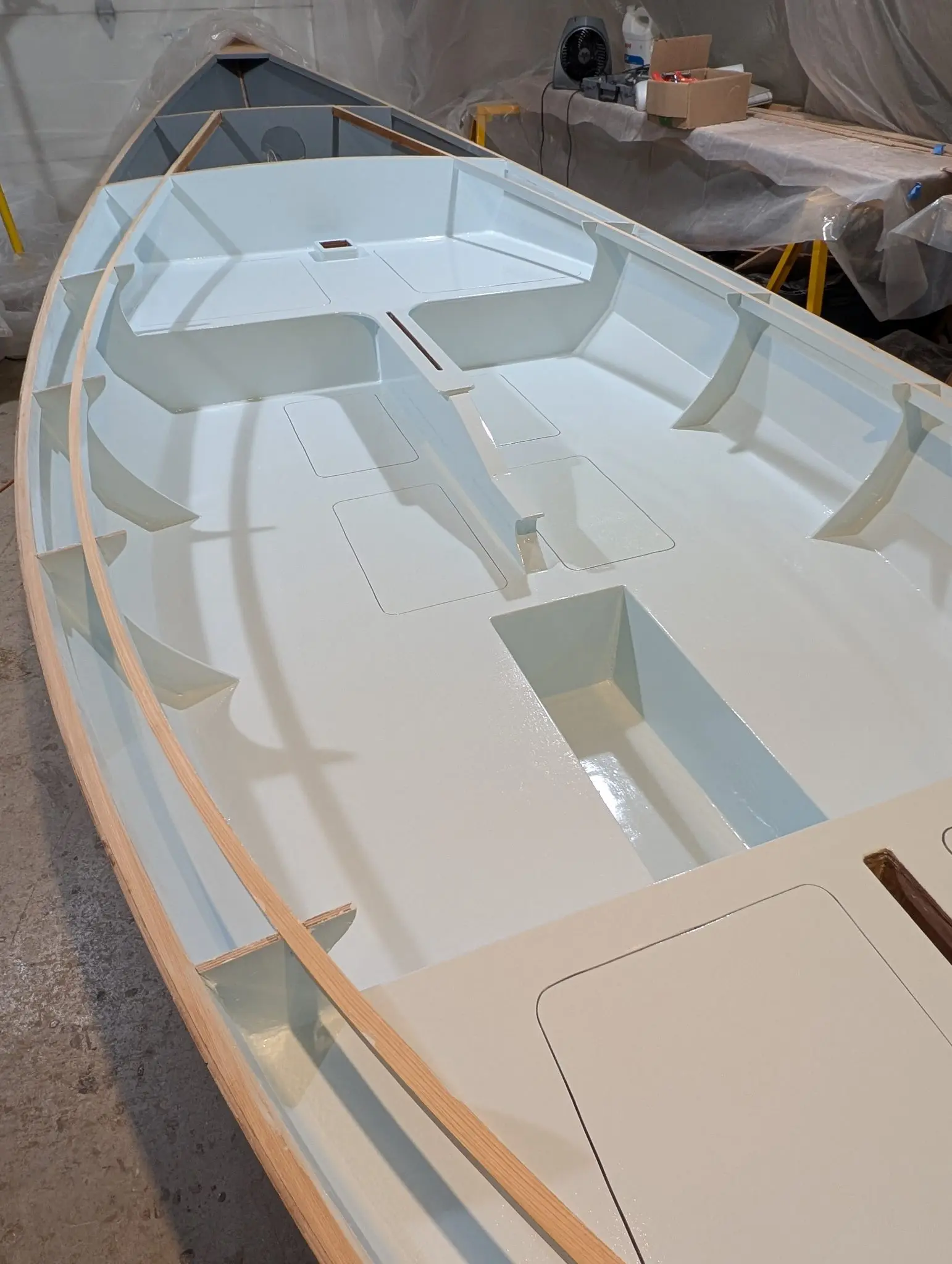
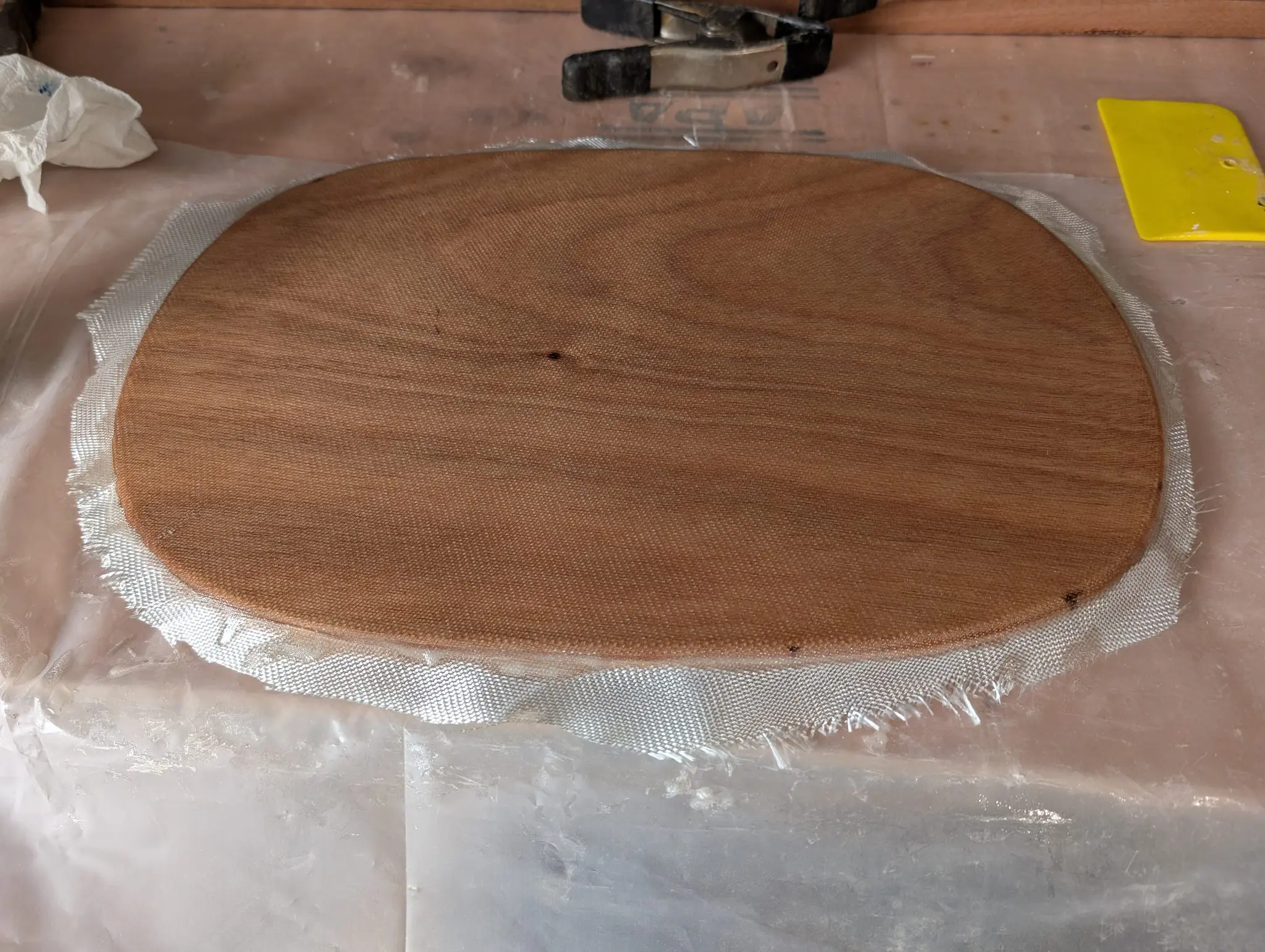
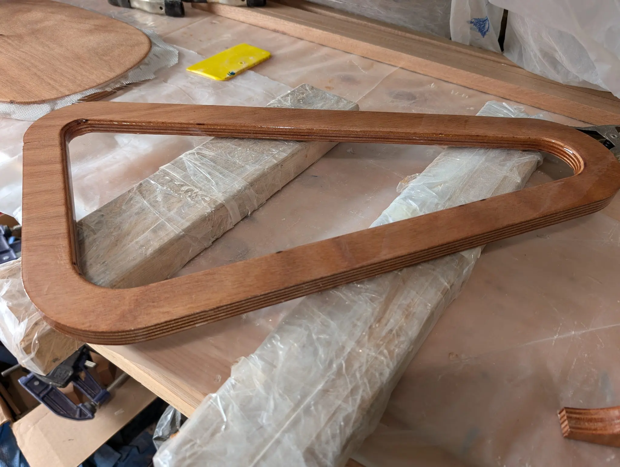
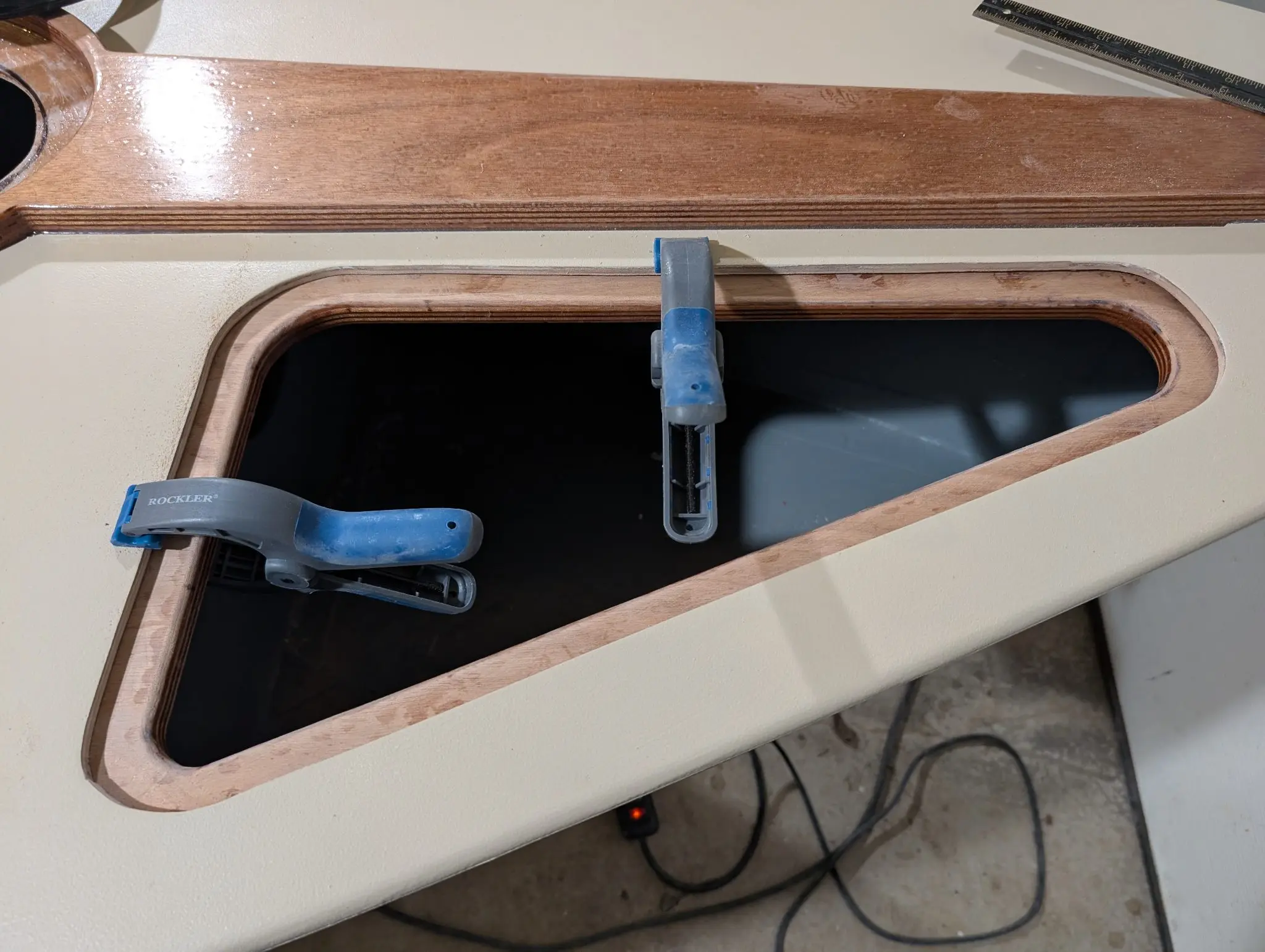
I wanted a break from painting, so I worked on FG for the pieces of the rowing seat and then getting the hatch lip installed in the anchor locker.
Photo 1 Photo 2 Photo 3 Photo 4 Photo 5
4 Jun 2025Paint & Finish
Friends don't let friends varnish stuff.
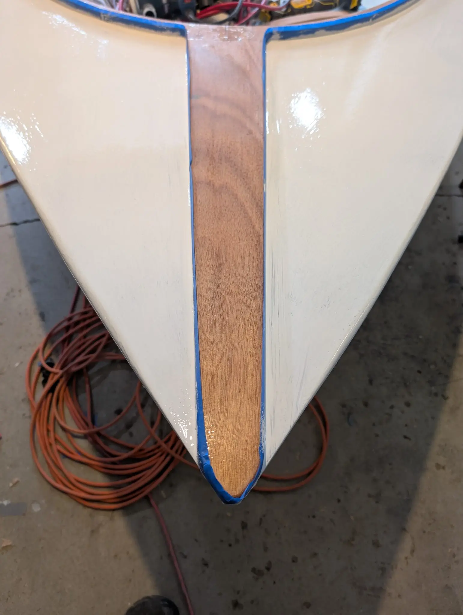
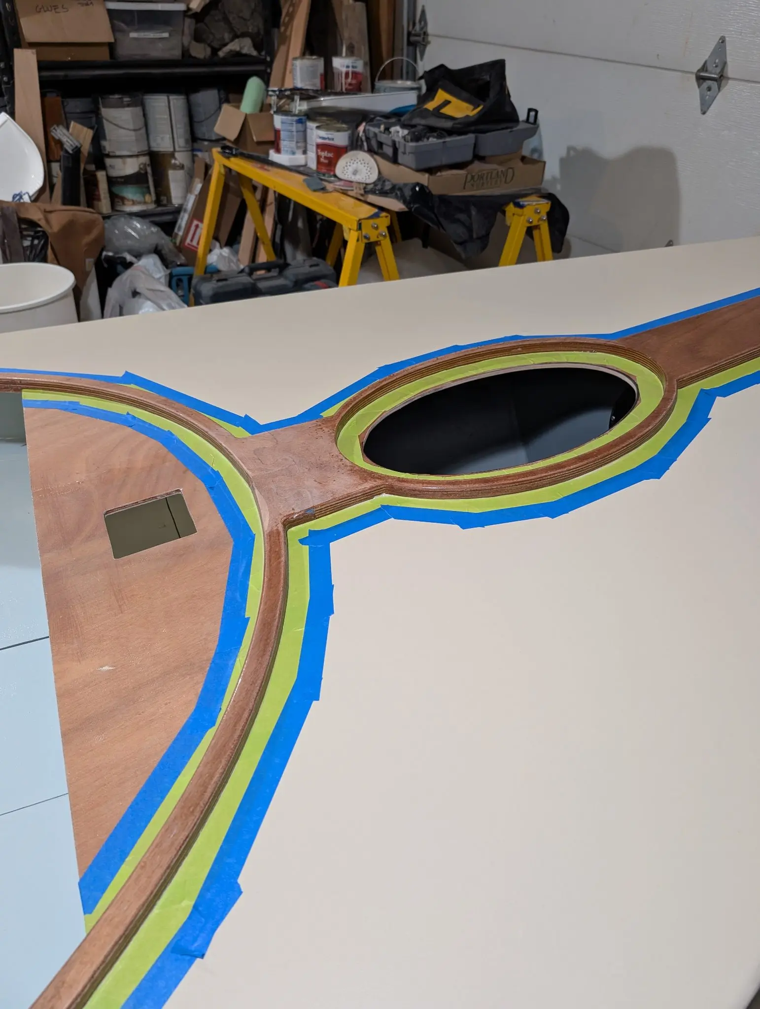
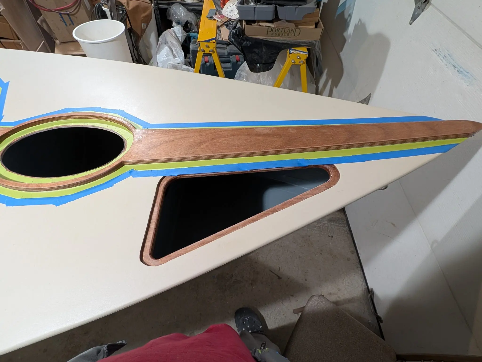
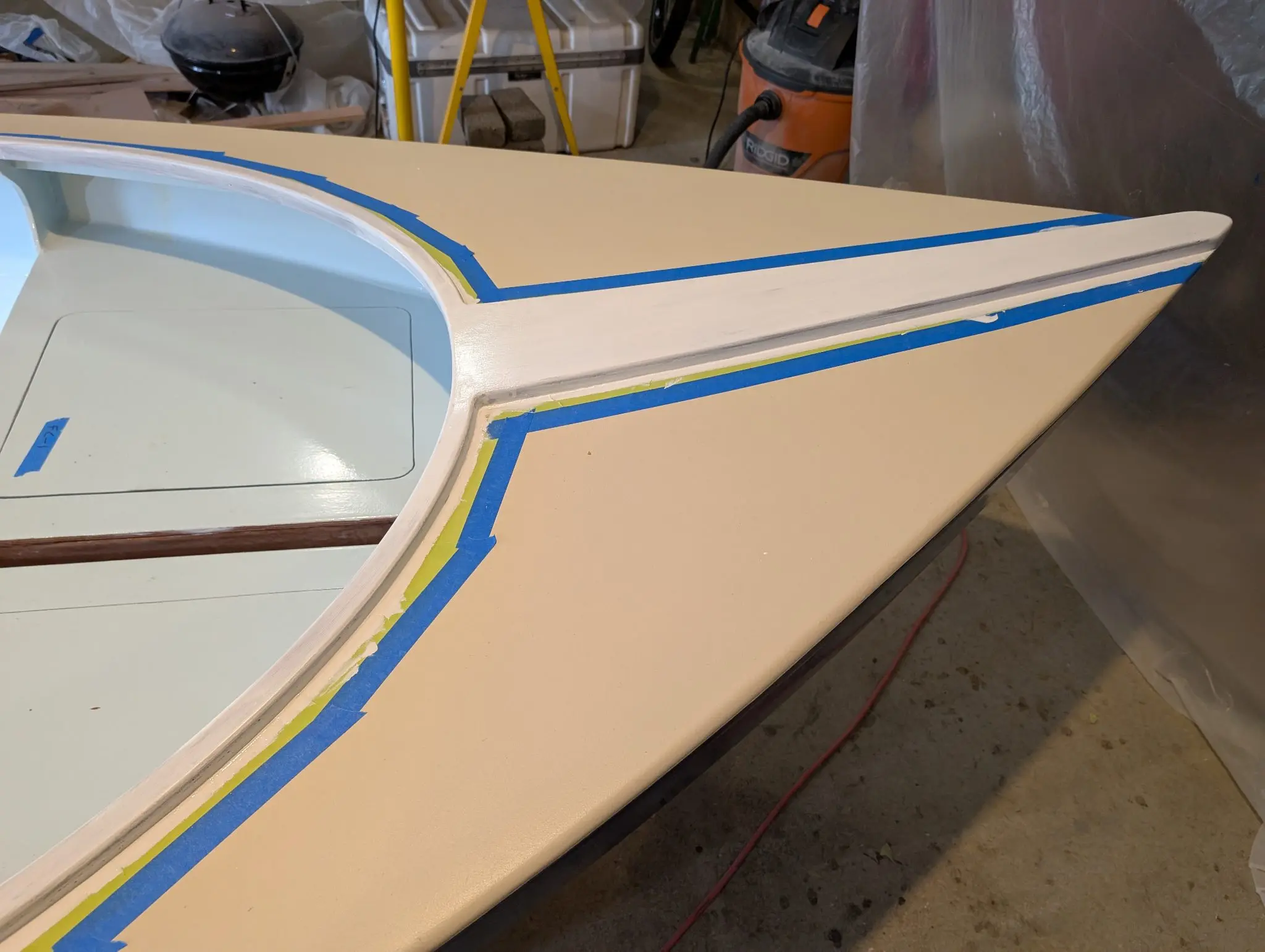
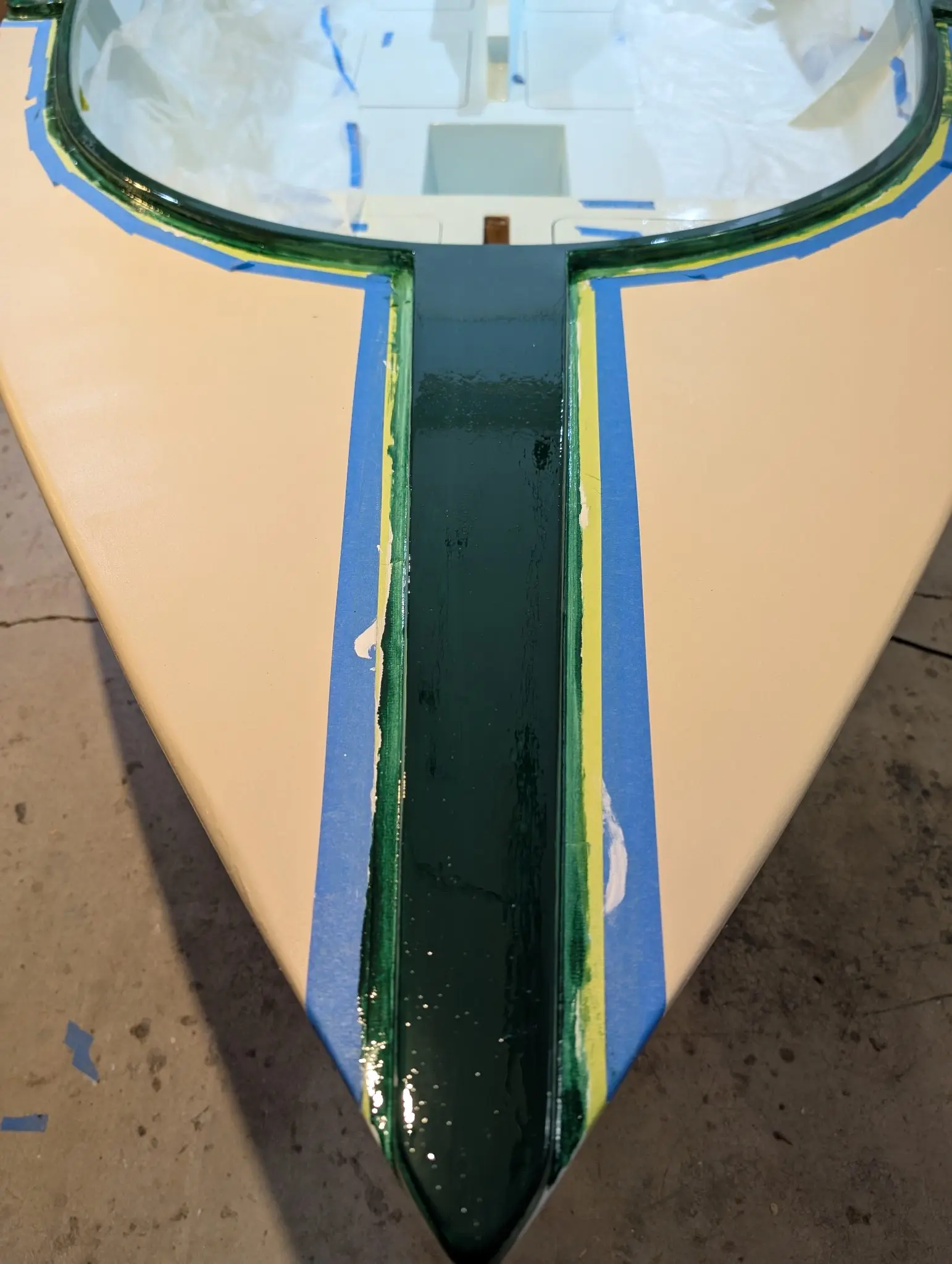
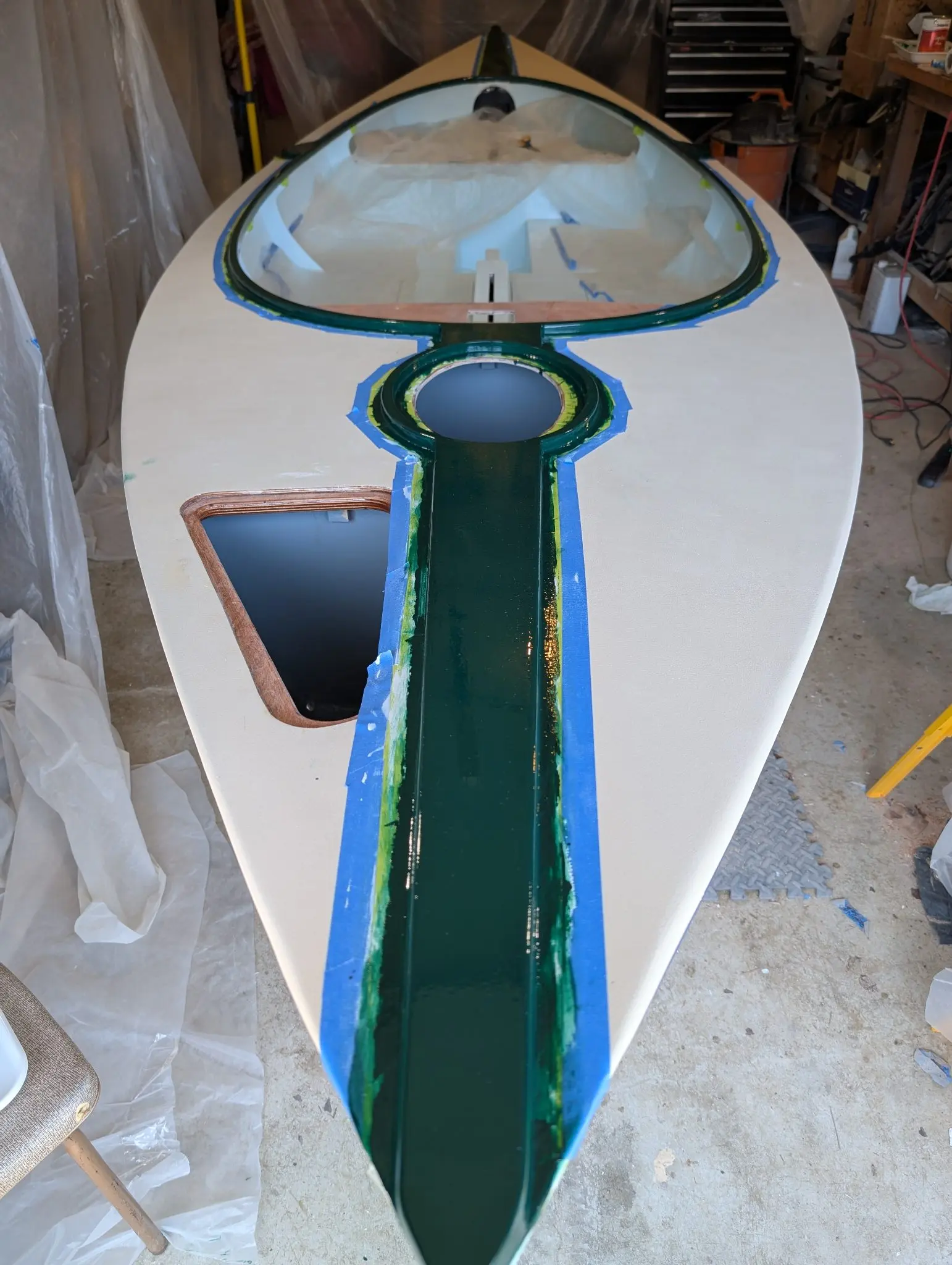
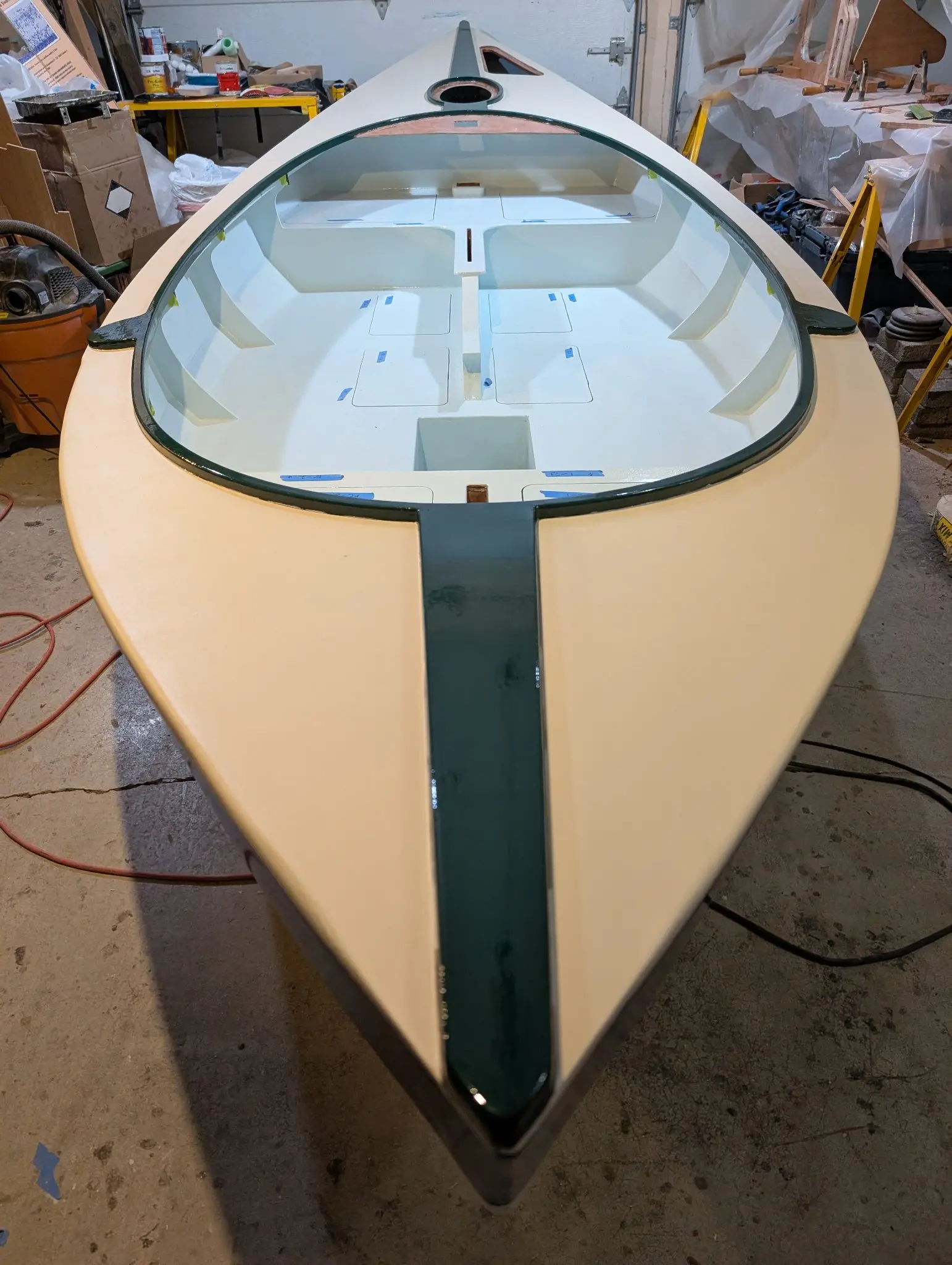
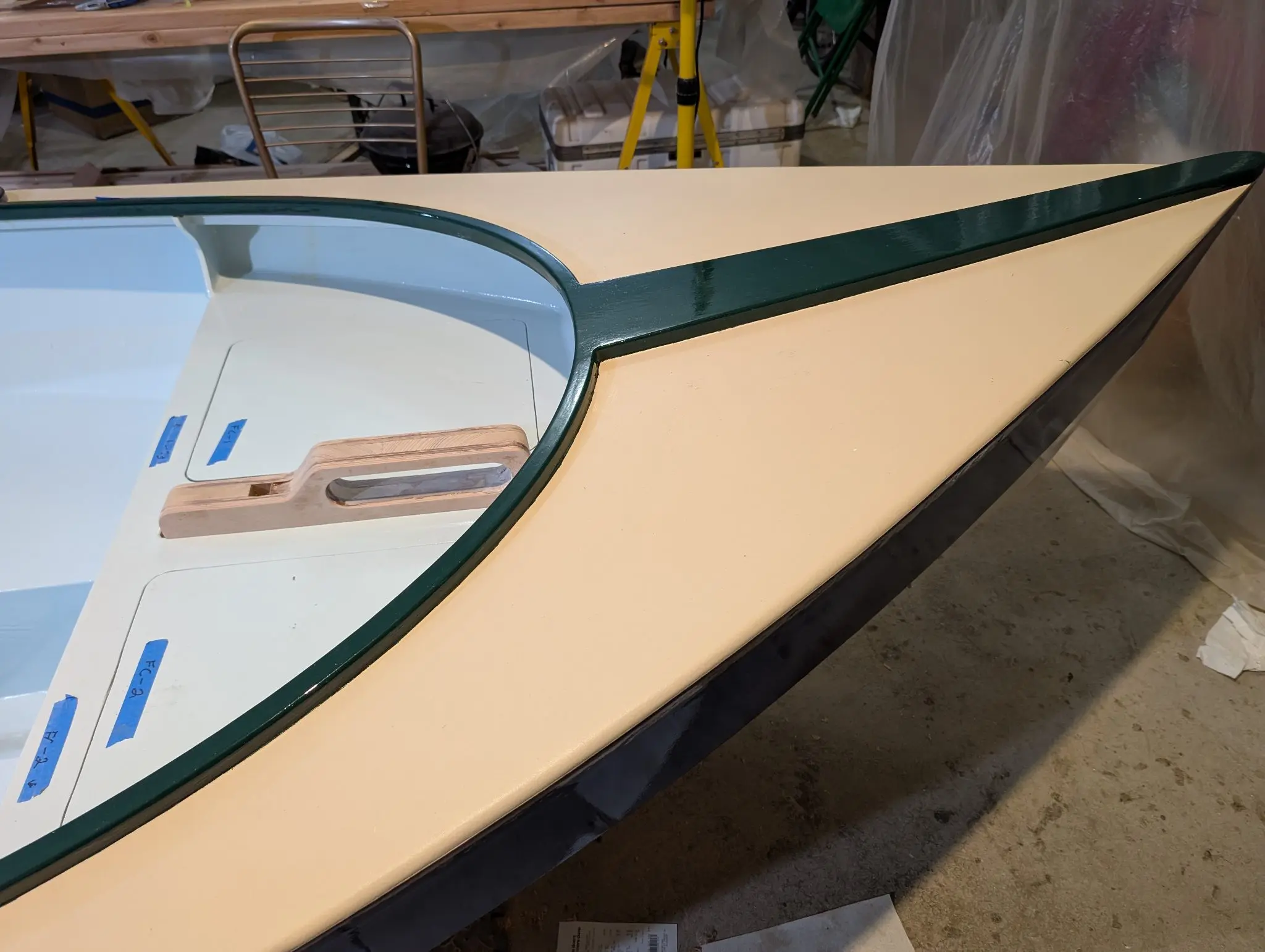
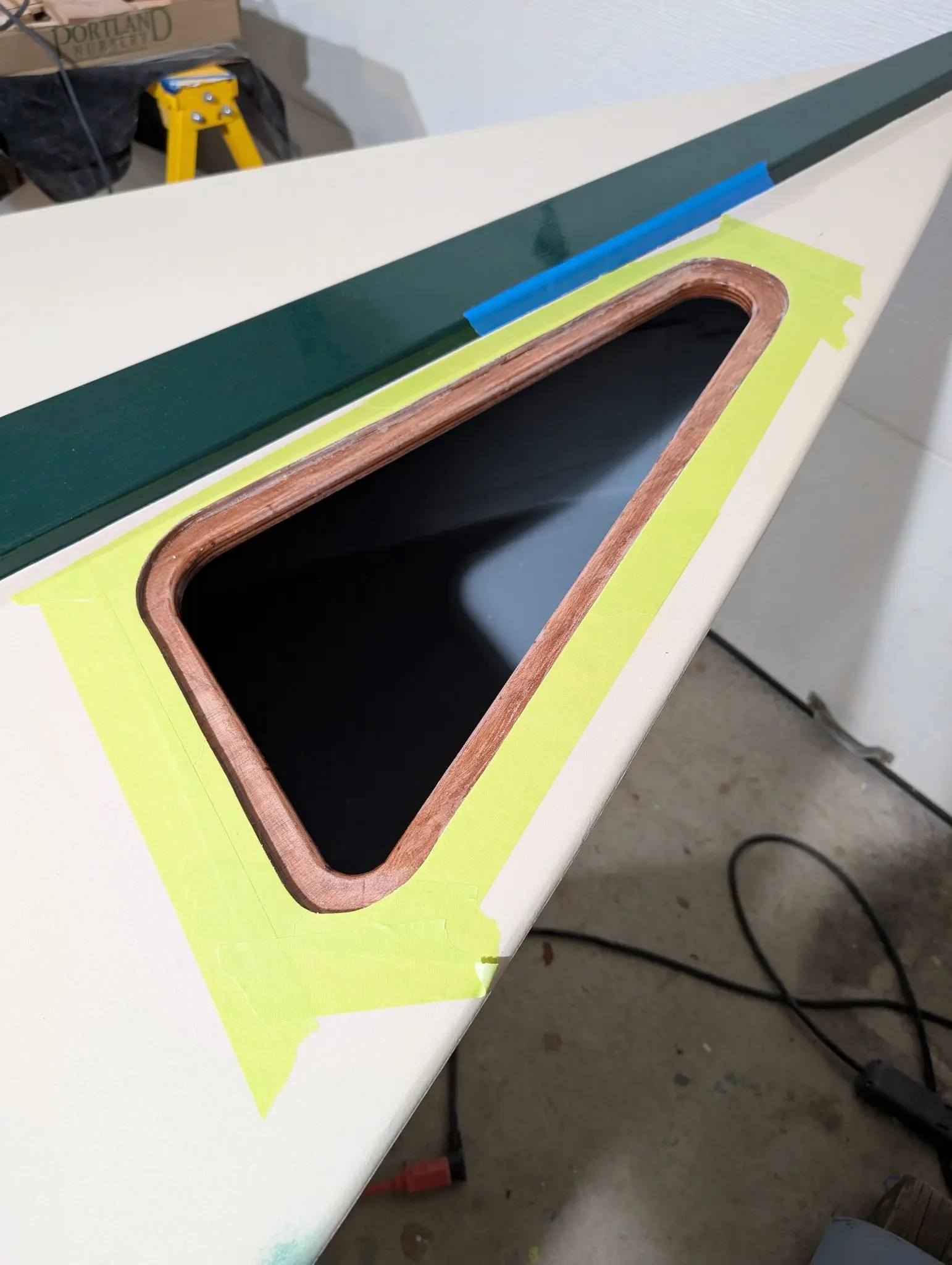
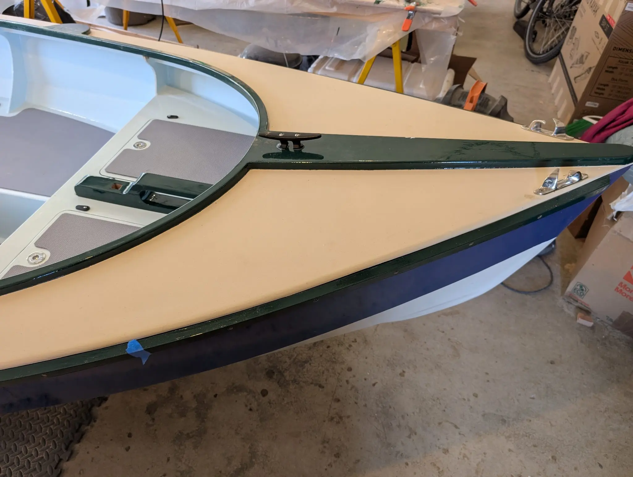
I hate varnishing. I love clear-finished wood, but the little time I have left on this Earth is not going to be spent varnishing wood. Everything on this boat will be painted, except the tiller, which will be finished with Tung Oil. The photos just show progress painting the coaming and king plank. Because the desk is non-slip, and therefore rough, I used the green painter's tape here. It's advertised for rough surfaces but is more expensive than the blue tape. It helped some but there was still some wicking of green paint under the tape. The solution was to mask off the coaming and paint over the green paint that escaped onto the deck. There are two coats of primer and three coats of Toplac Plus in Donegal Green.
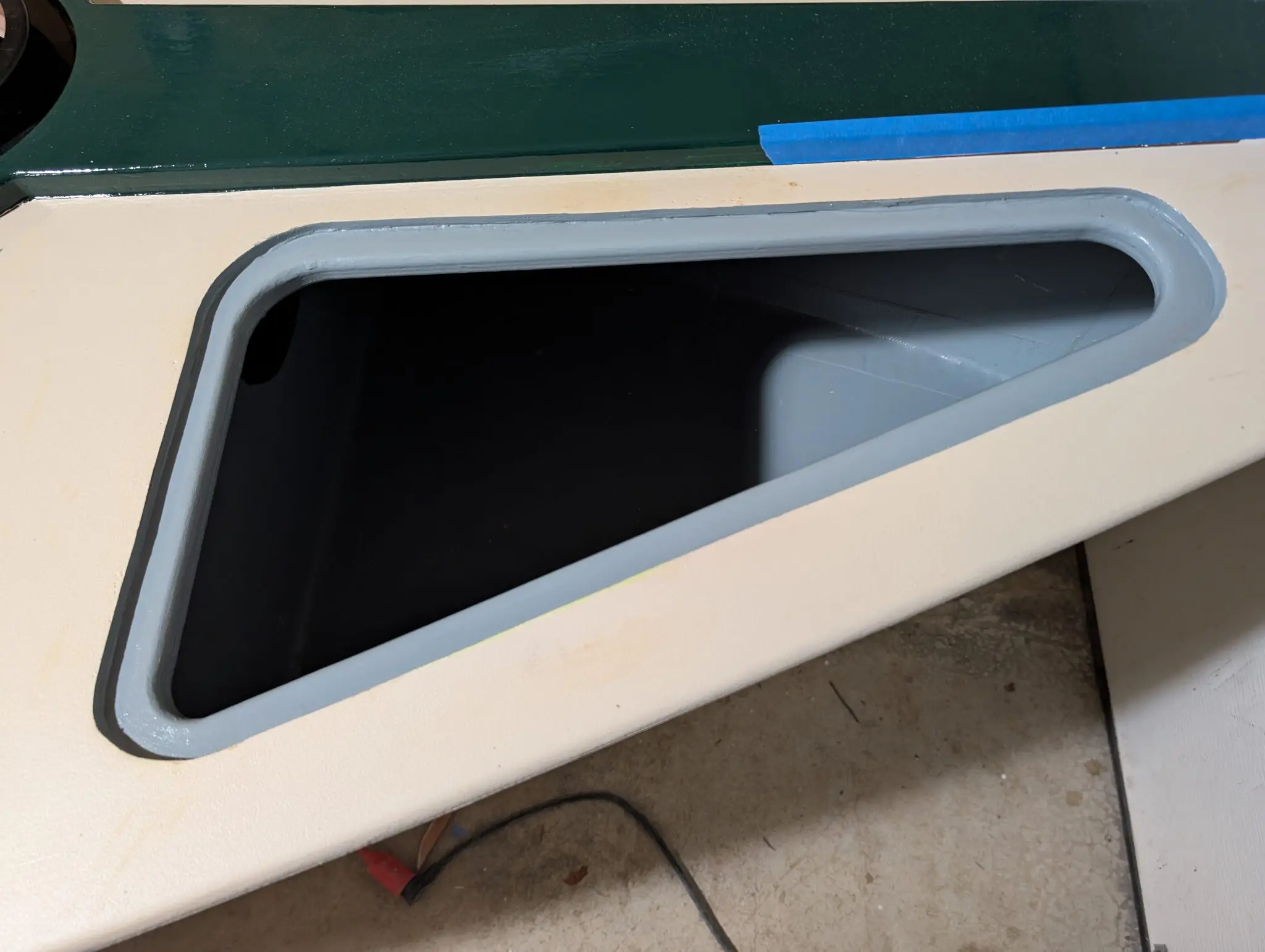
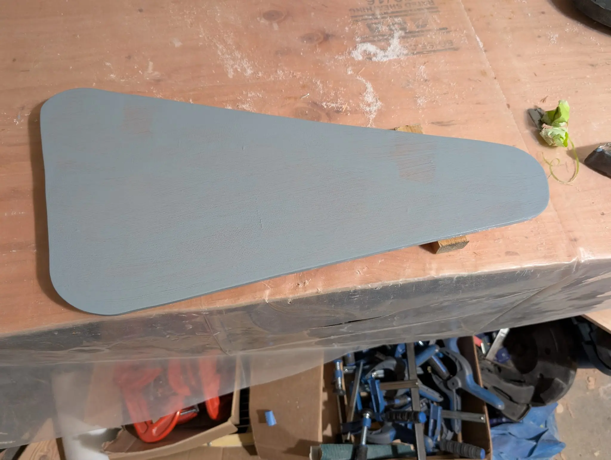
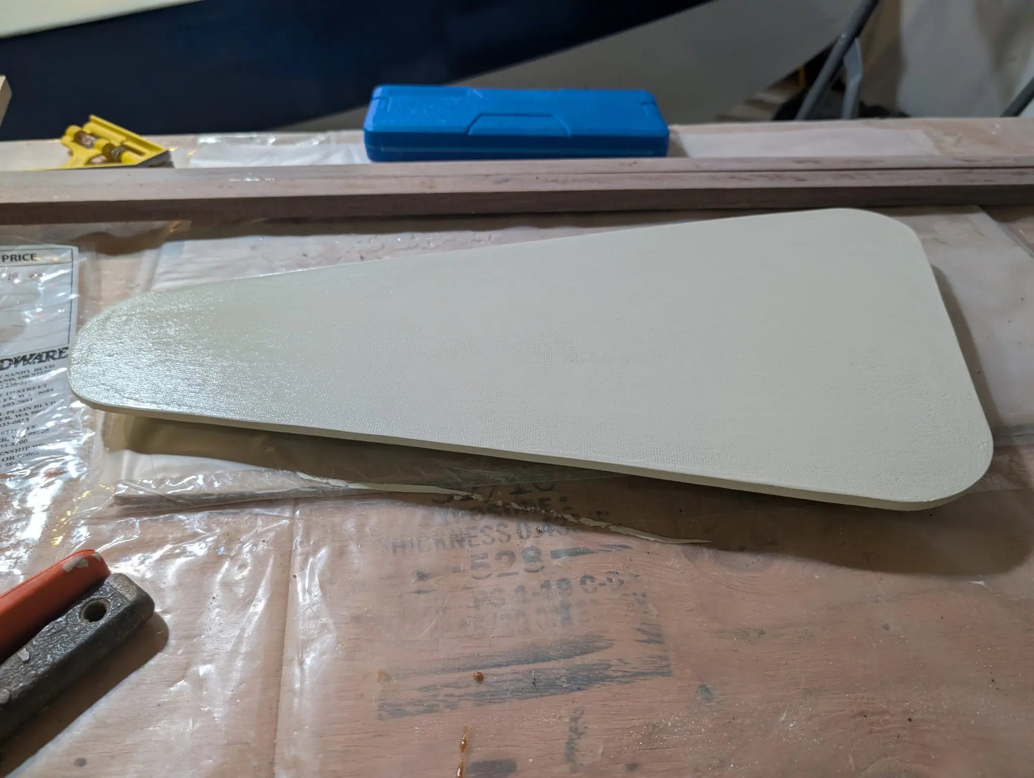
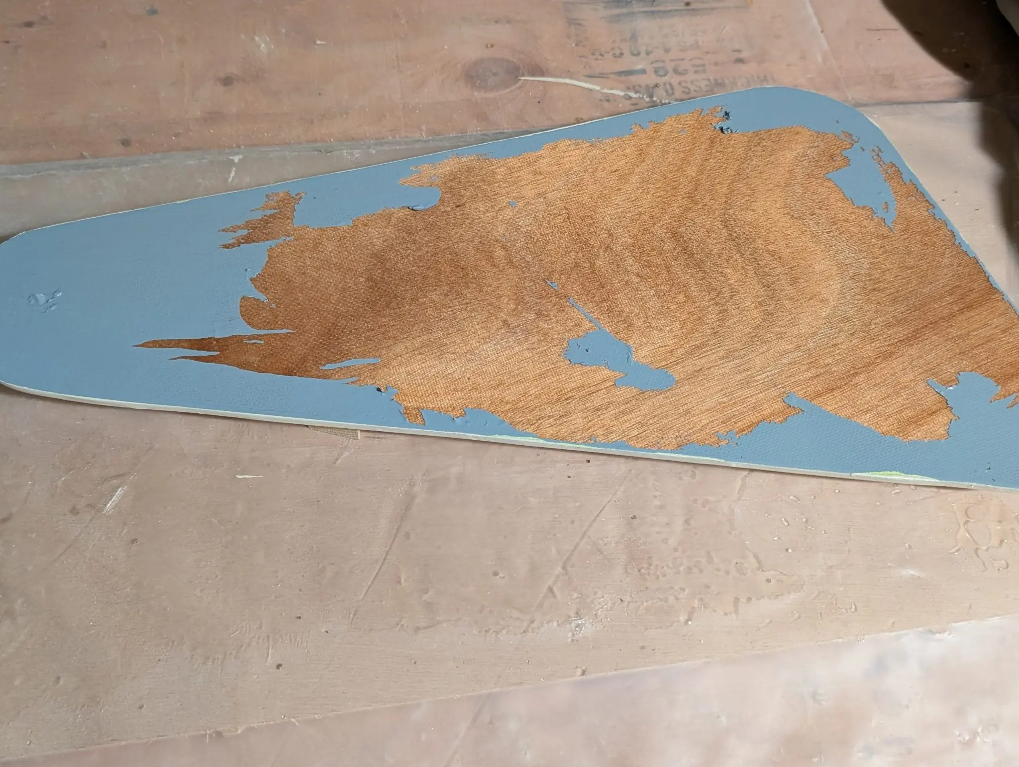
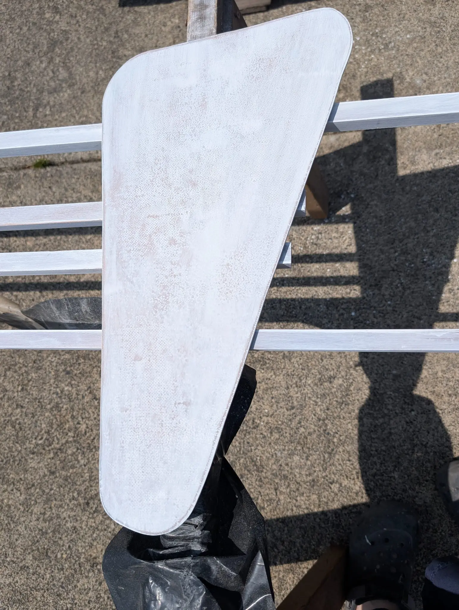
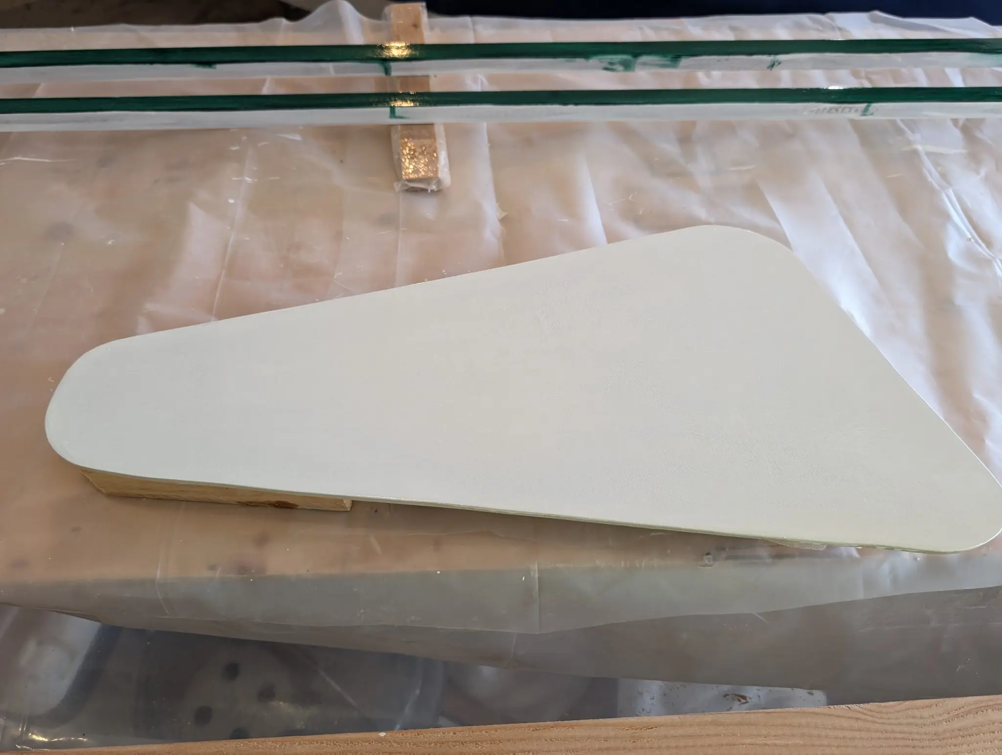
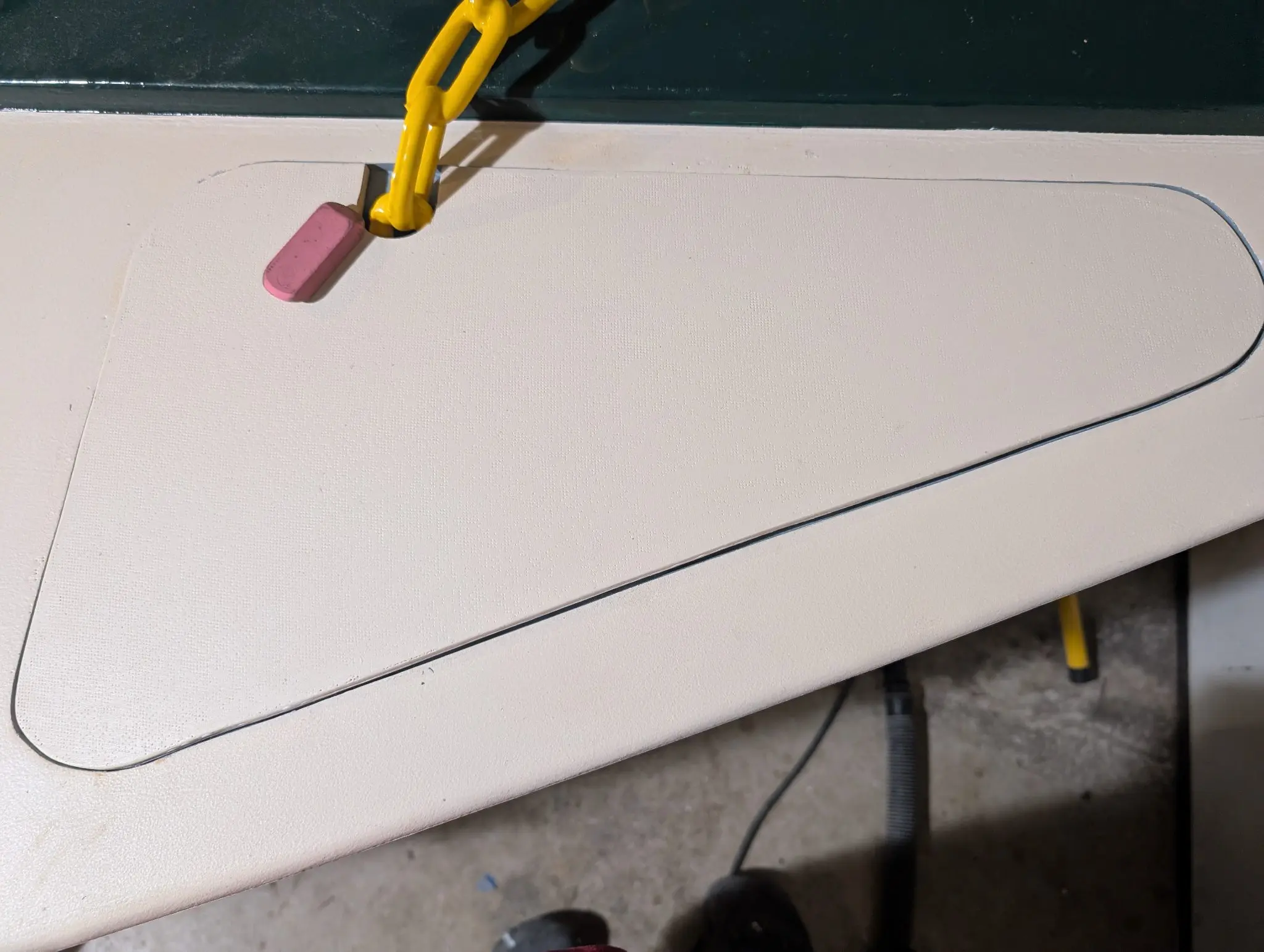
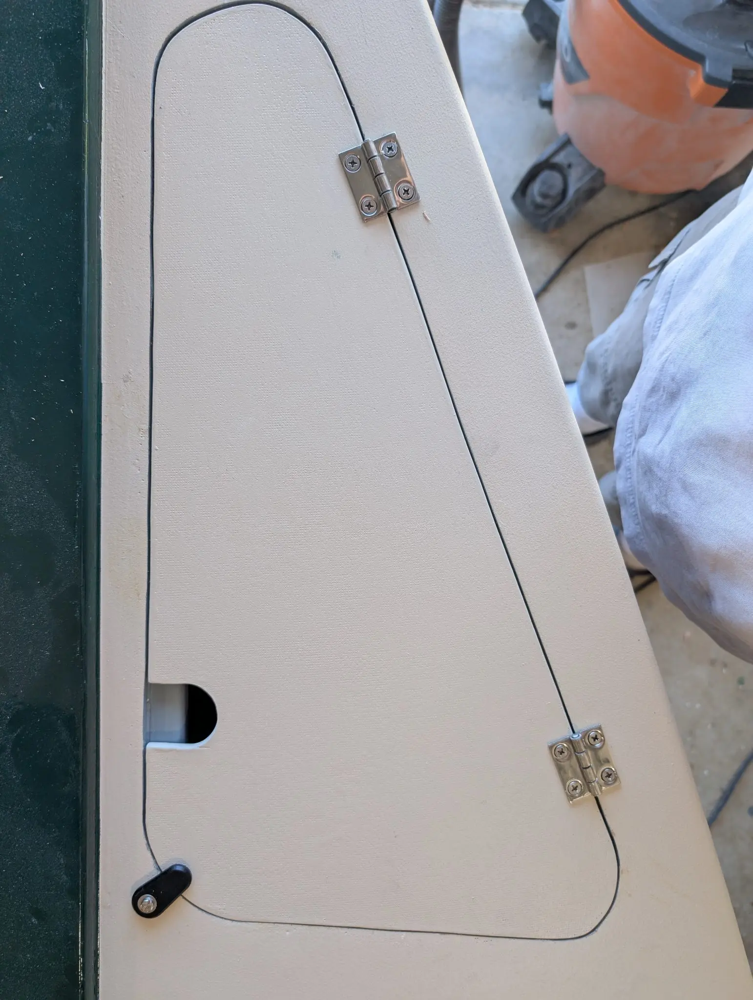
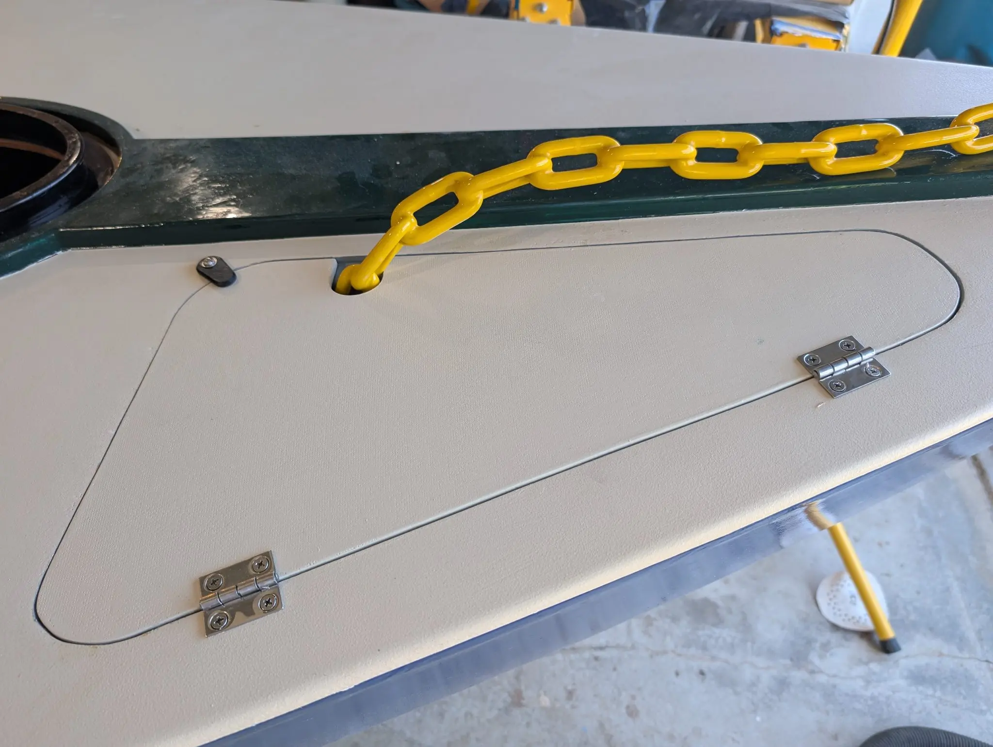
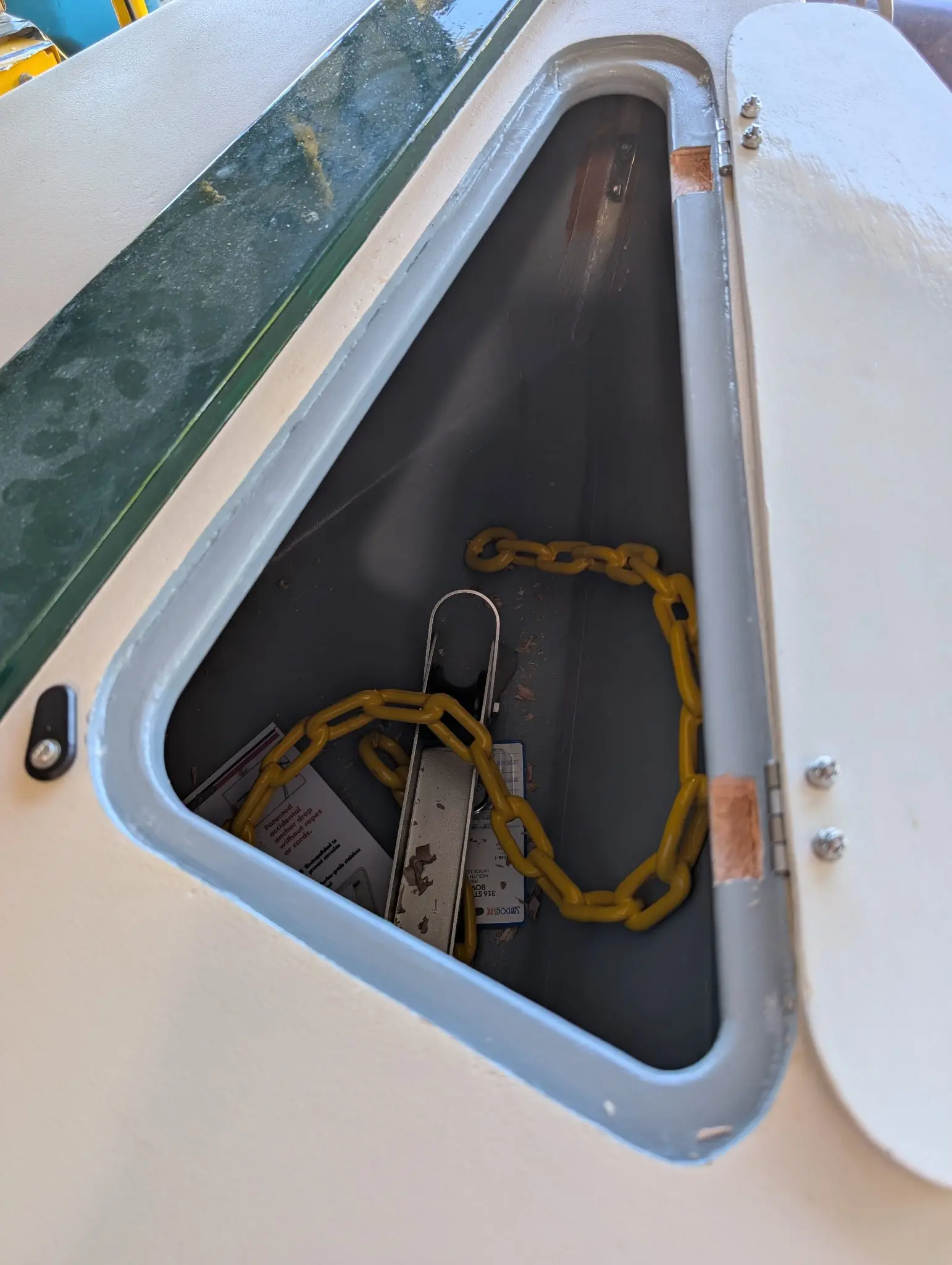
The photos are about finishing up the anchor locker hatch. In 3 you can see how I painted latex over epoxy, and it looks pretty good. A while later, in 5 you can see a near-total failure of the latex to hold onto the epoxy. I am not sure what happened here. I have been painting latex over epoxy for decades and have never had a failure. Elsewhere on the boat, the same paint has bonded tenaciously to the exact same type of epoxy. I am not sure what happened. I stripped off the failed paint, primed it with Pre-Kote Plus and repainted. It is holding on fine after that. In 8-11 you can see the placement of the hinges, cutout for the chain, and the hatch dog. This hatch cover doesn't have a gasket seal because the anchor locker has drains on port and starboard to let water out.
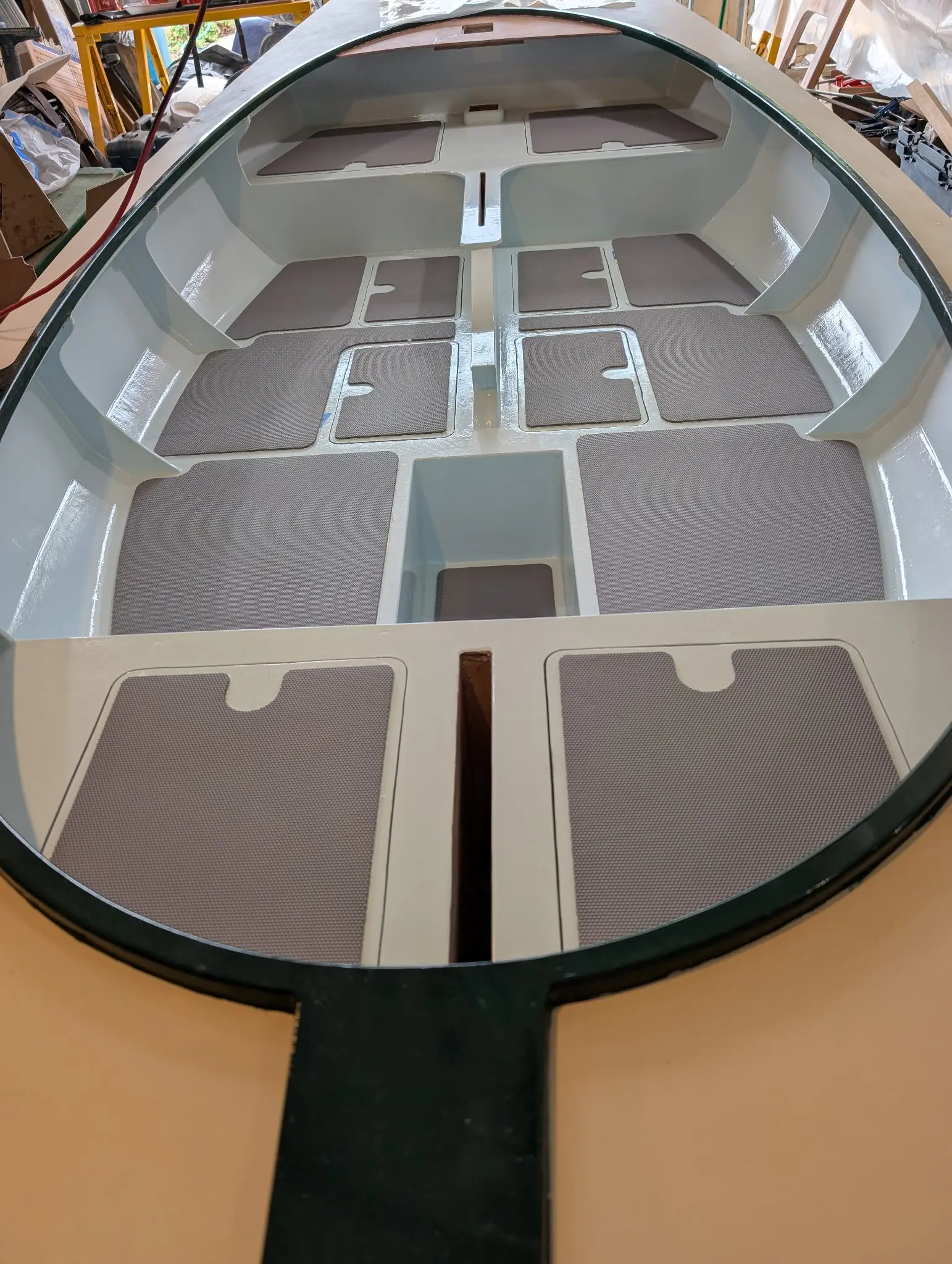
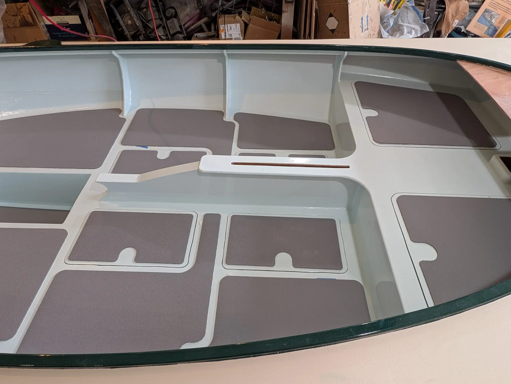
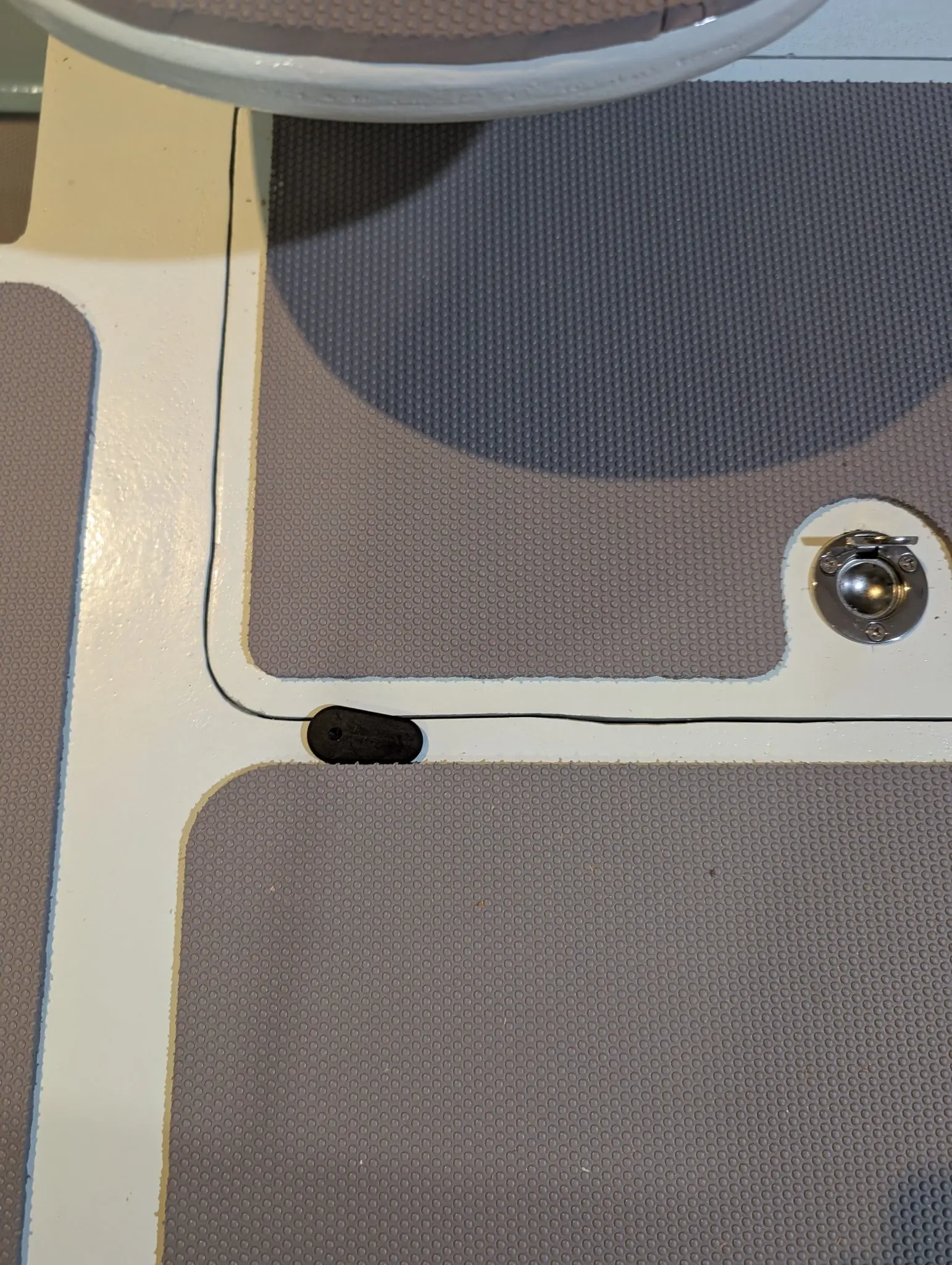
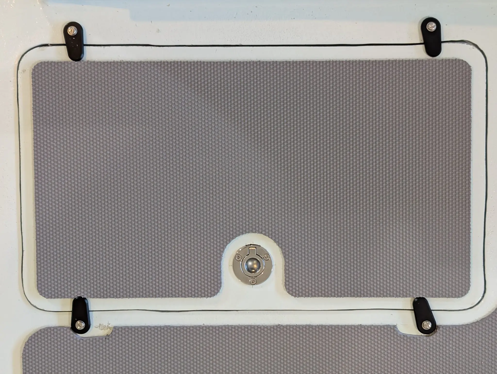
I purchased the non-skid foam package from CLC. I like the idea, and I think it looks good. The semicircular cutouts are for the hatch pulls. It was pretty easy to apply but I should have thought it through a bit more and maybe dry fit everything. As it is, in some places I have had to trim the foam to make room for the hatch dogs (see 4). Also, I am thinking the screws for the hatch dogs will let water in, maybe not a lot and maybe not fast. With all the effort to have sealing gaskets on the hatches, this seems like bad design. Perhaps there is a better way, but not now.
Photo 1 Photo 2 Photo 3 Photo 4
Chapter 12
Hardware & Fit-Out
Cleats, rudder and centerboard, tiller, oarlocks, deck gear.
3 daysfrom July 2025
16 Jul 2025Hardware & Fit-Out
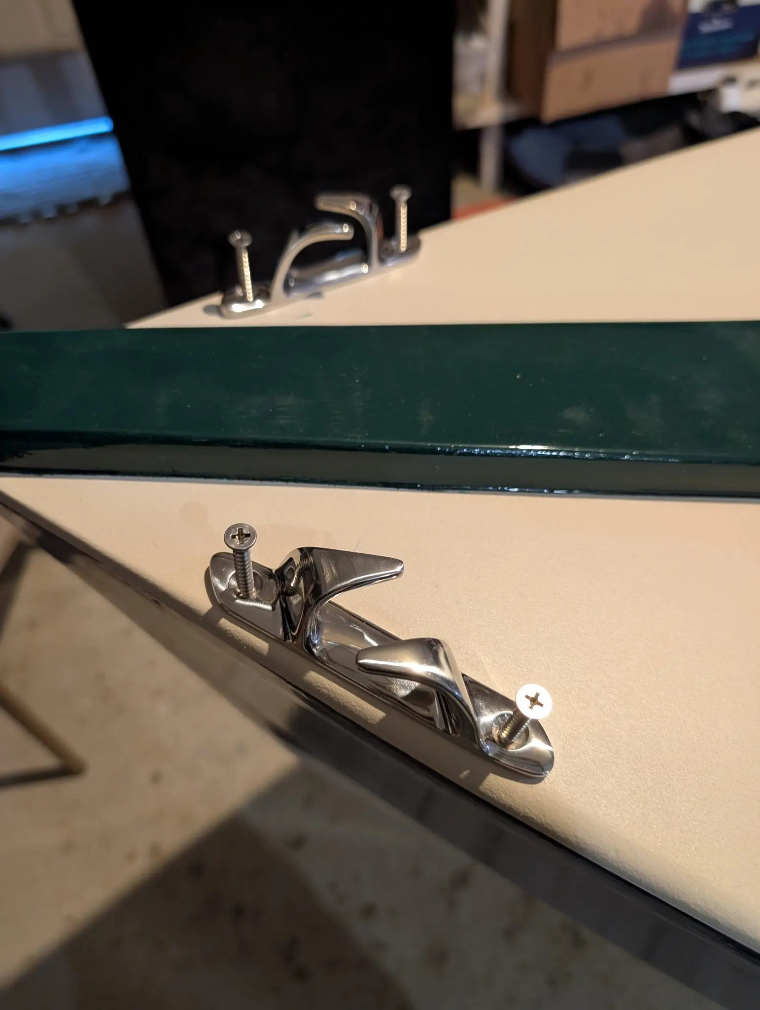
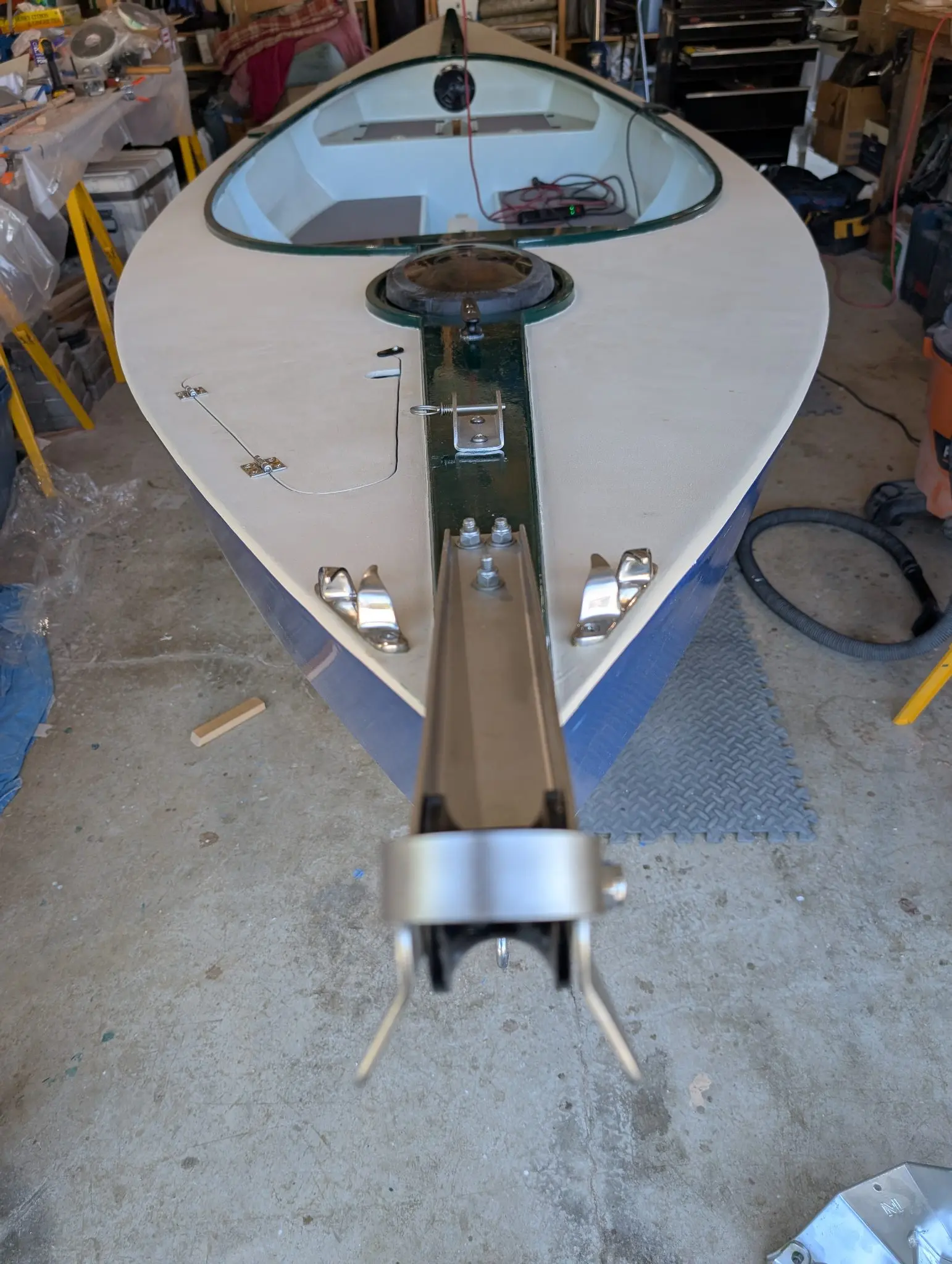
Deck hardware
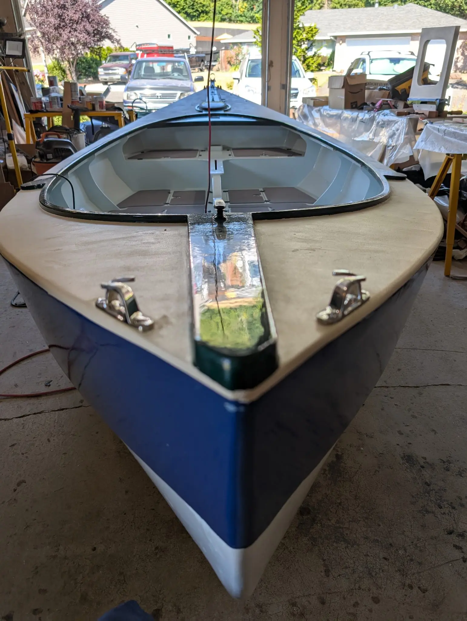
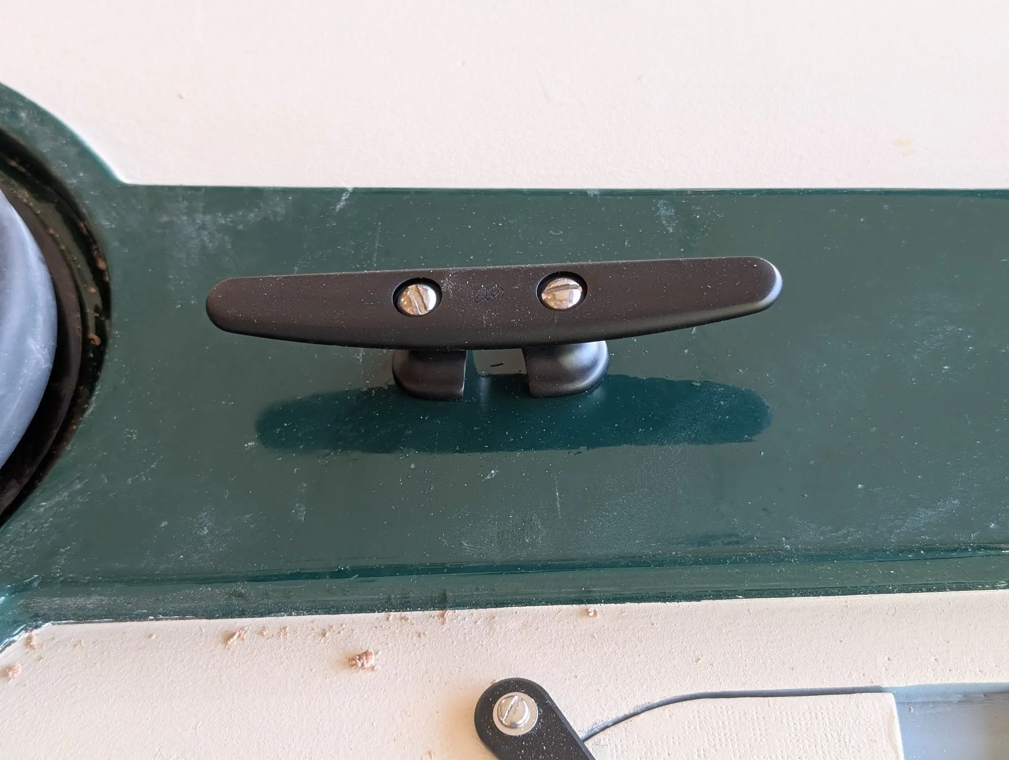
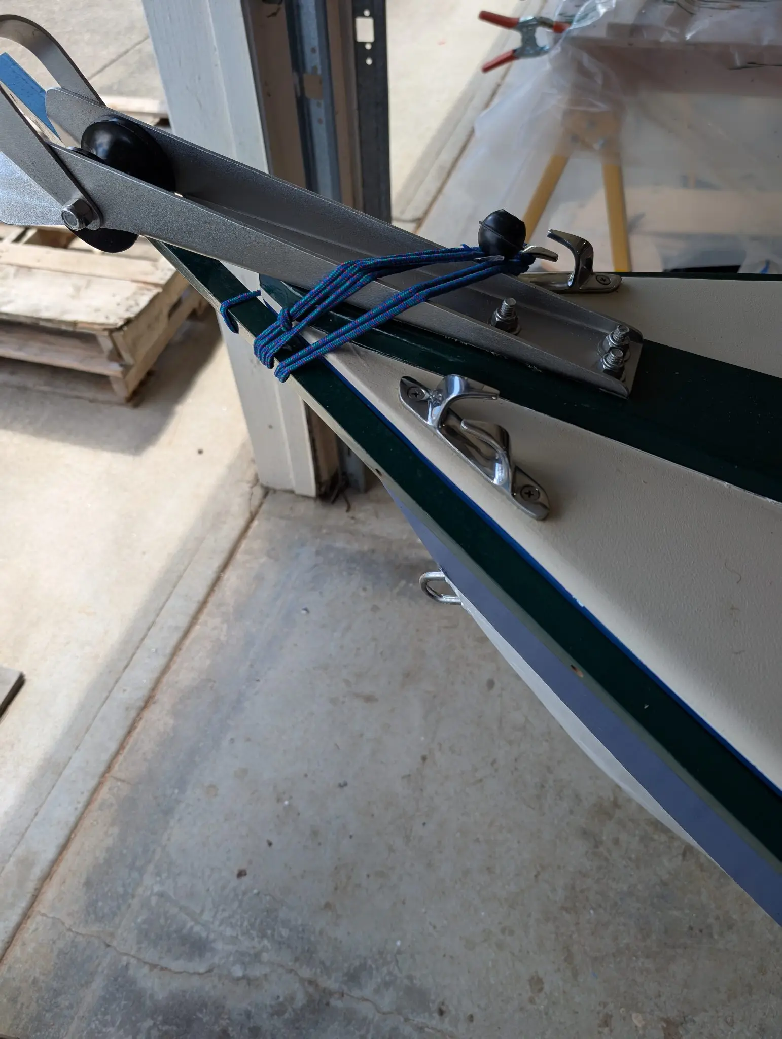
I began installing various deck hardware components, including cleats, chocks, and the anchor pulpit. The main horn cleats, fore and aft, as well as the anchor pulpit, are through-bolted on the deck. They are bedded with 3M 4200 marine silicone sealant. The chocks are screwed into the sheer clamp and bedded with Dolphinite.
Photo 1 Photo 2 Photo 3 Photo 4
25 Jul 2025Hull Exterior
Springing the rub rails
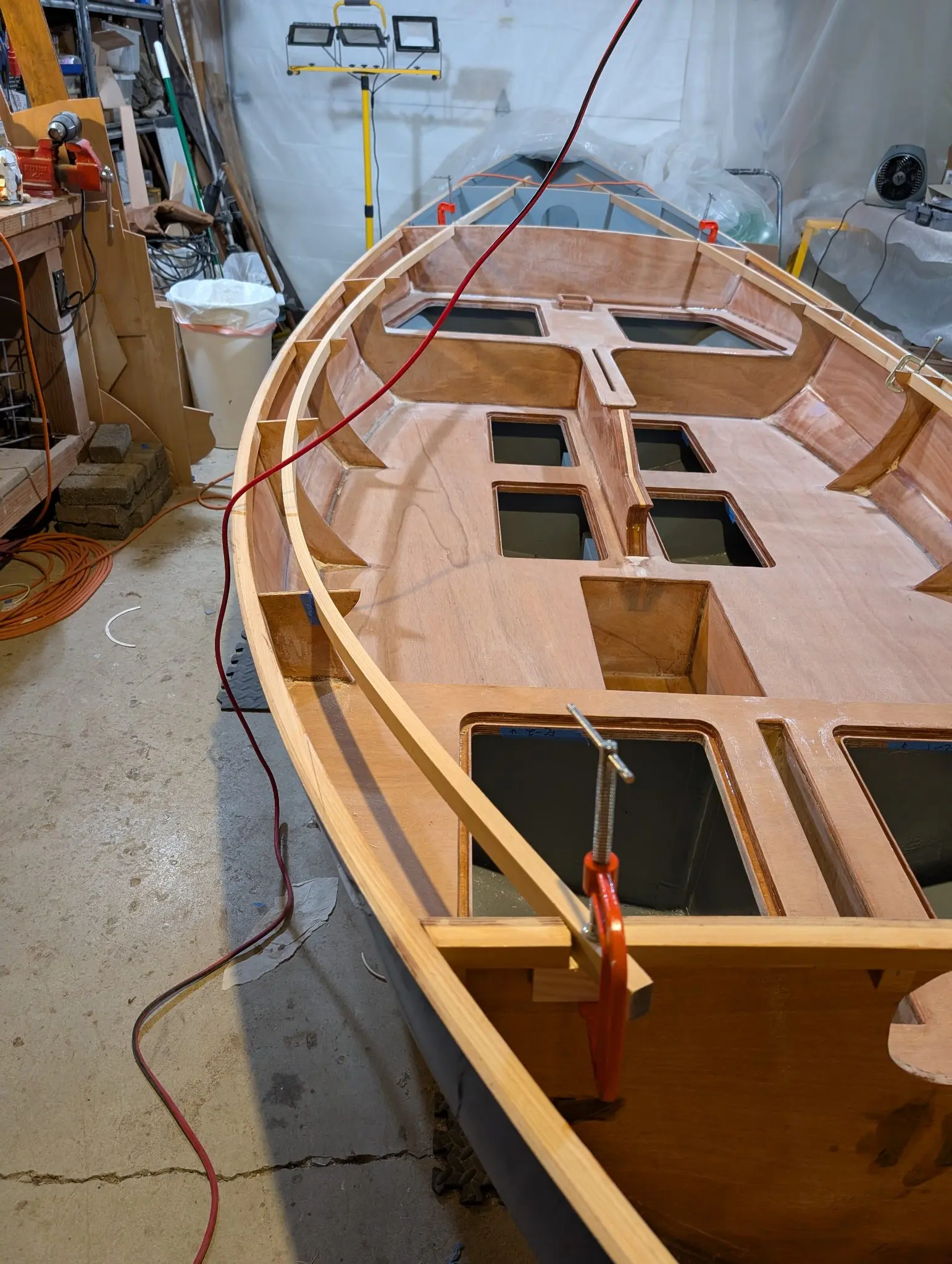
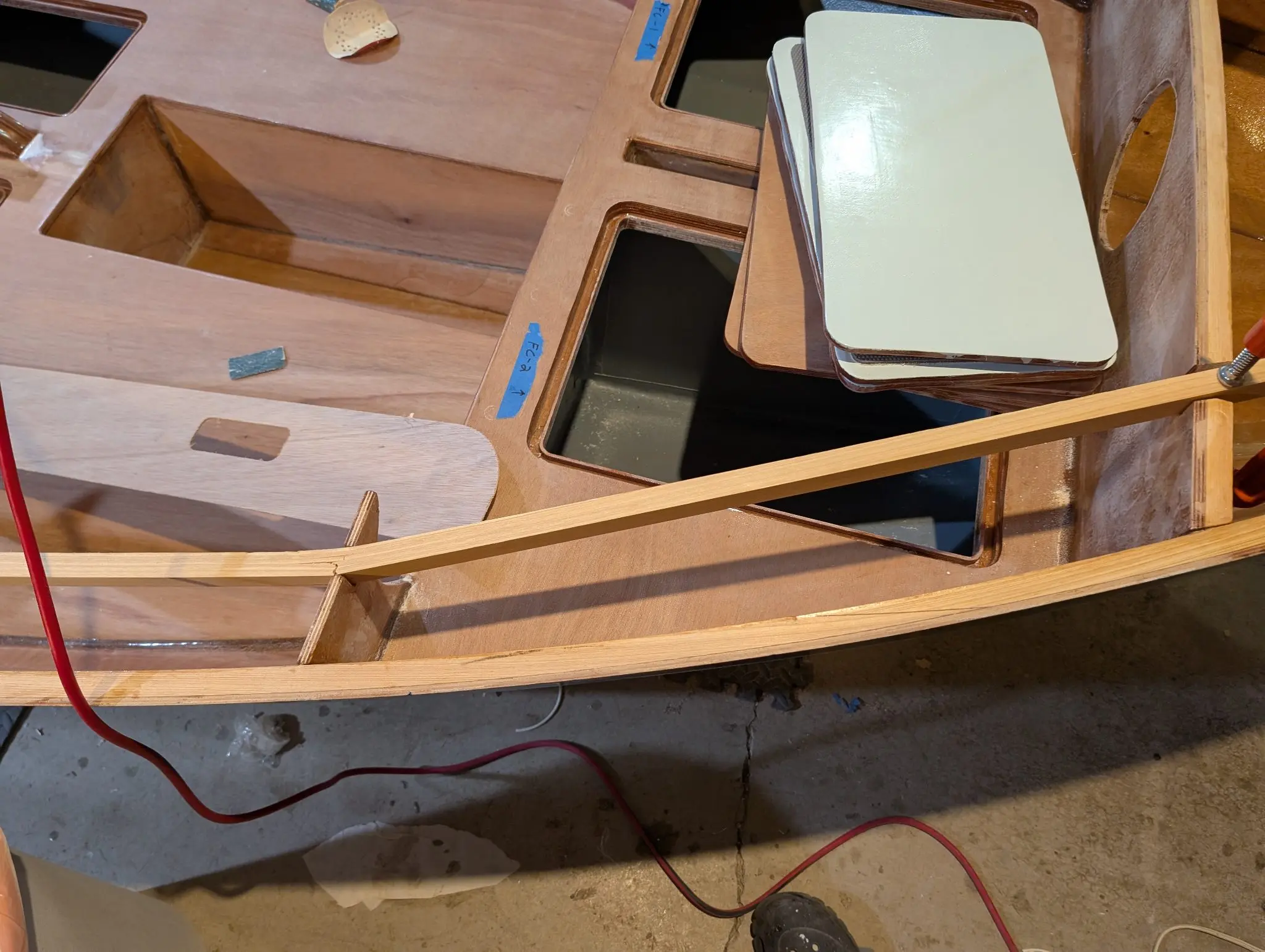
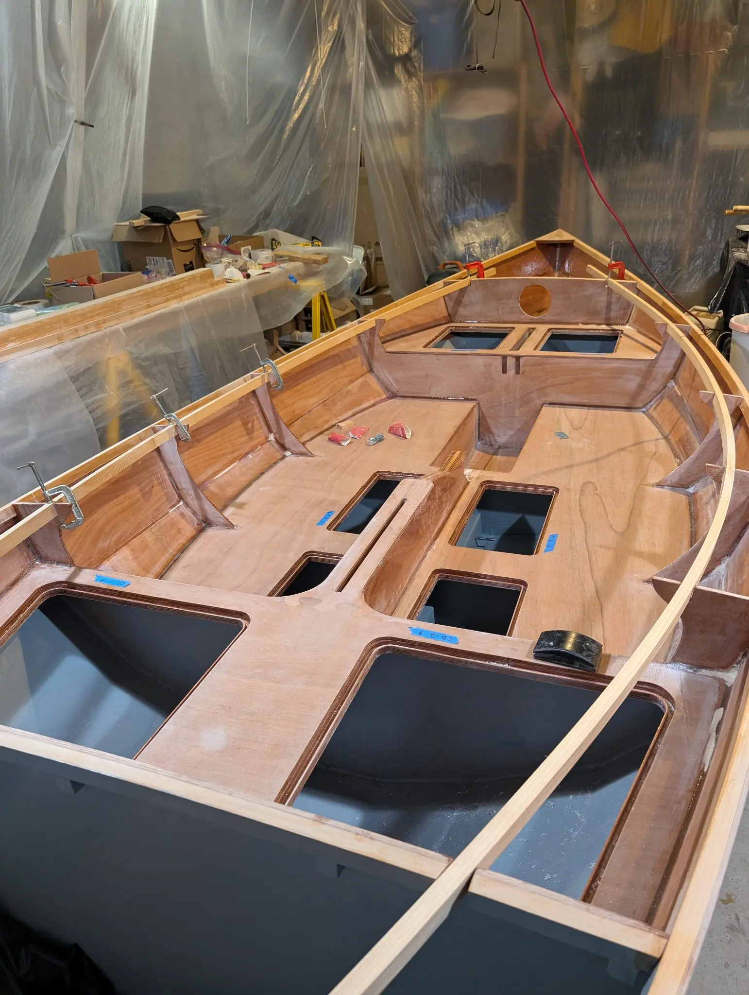
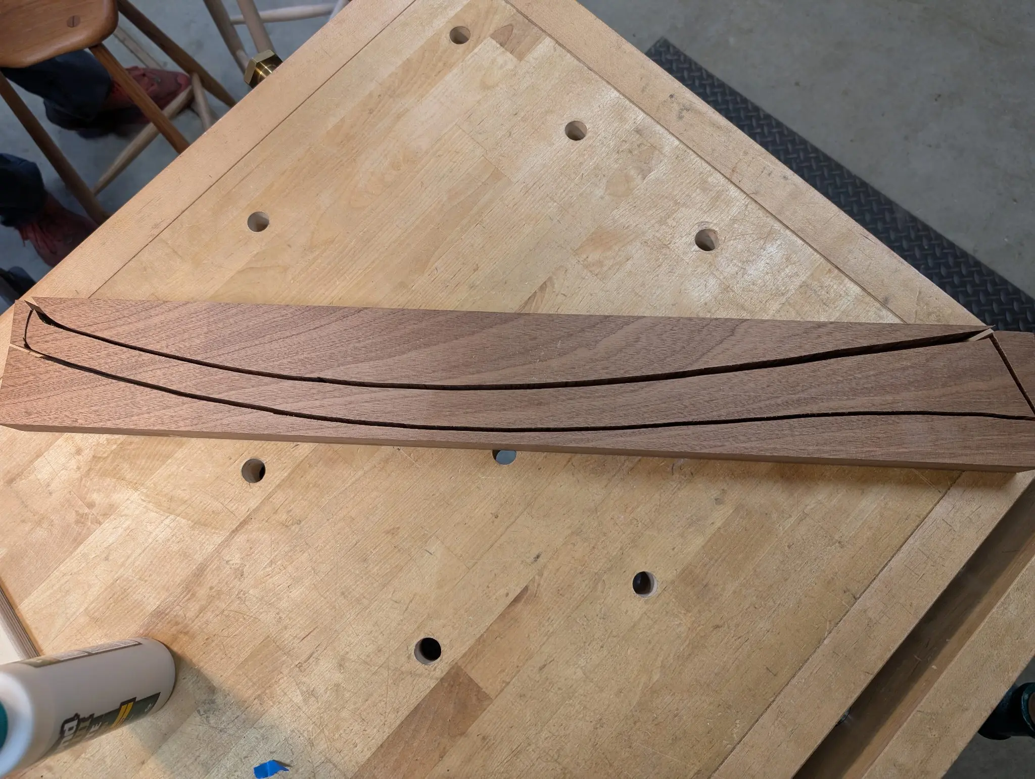
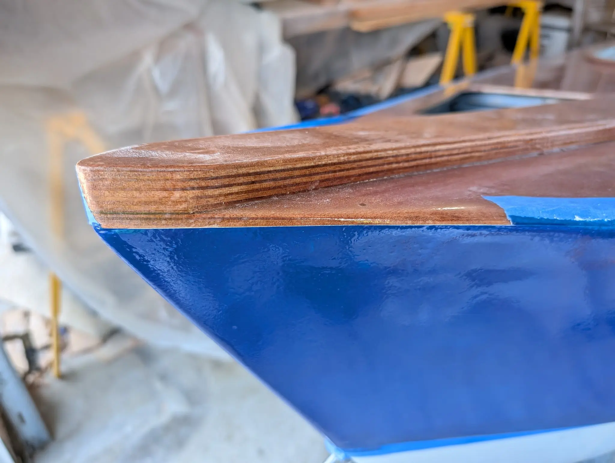
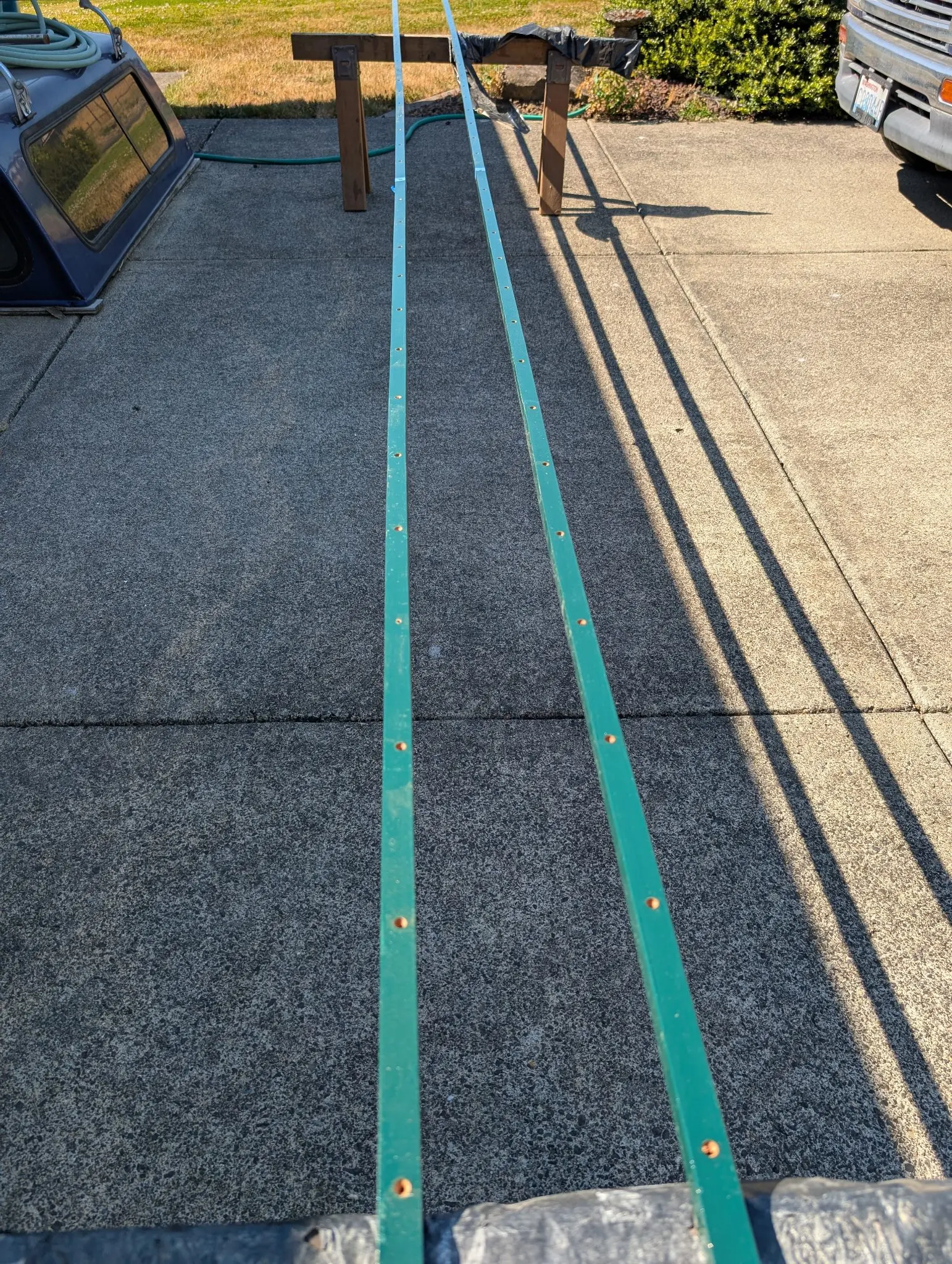
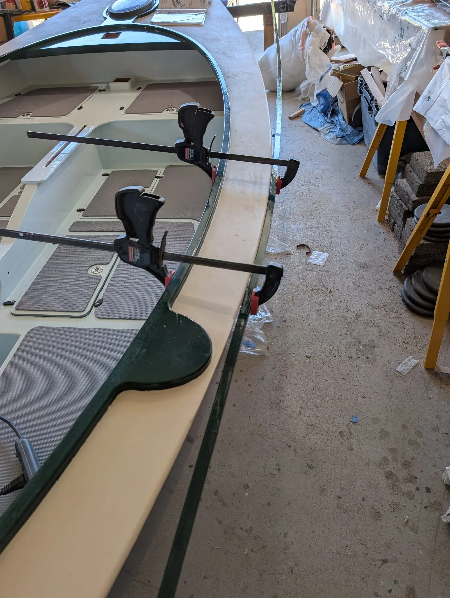
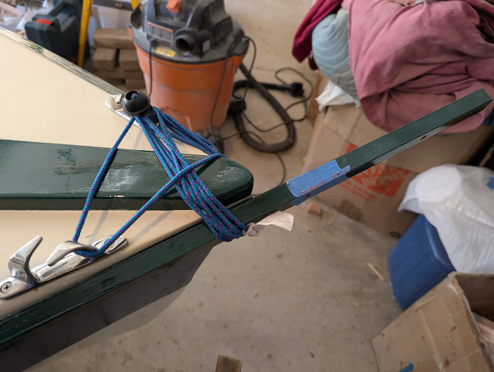
The rub rails are built up of three scarfed pieces of Mahoganoid wood that are primed and painted with Toplac Plus. The fasteners are screwed through the hull and into the sheer strake and bedded with Dolphinite. It was easy to place and fasten the rails in the middle of the boat because I could clamp them using the coaming. It was much more difficult in the bow and stern because there was nothing to clamp to. I had to get creative with bungee cords and the like. In retrospect, I think I should have started at one end or the other and worked towards the other end of the boat. I also should have asked for someone's help. This really isn't a one-person job.
Prior to scarfing, the pieces of the rub rail were given 2 coats of epoxy to seal the wood
Priming is not strictly necessary for paint adhesion, but it definitely helps to create a nice smooth finish
After final painting the fastener holes were pre-drilled and countersunk. The SS screwheads and the hole between the rub rail and hull will be bedded with Dolphinite
Clamping is easy amidships
Awkward to pull it all tight at the bow and stern
Finished! Not perfect, but good
Stainless steel half-round (channels, not solid) pieces are screwed into the rub rails for even more protection. The fasteners are bedded with Dolphinite.
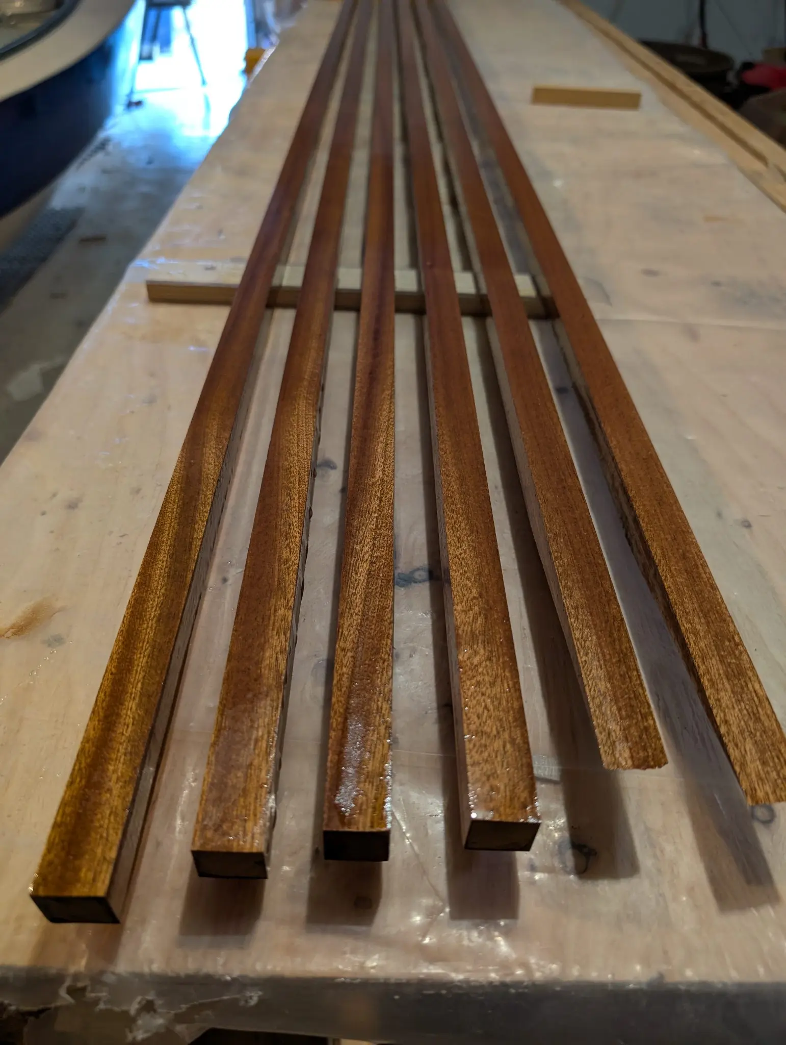
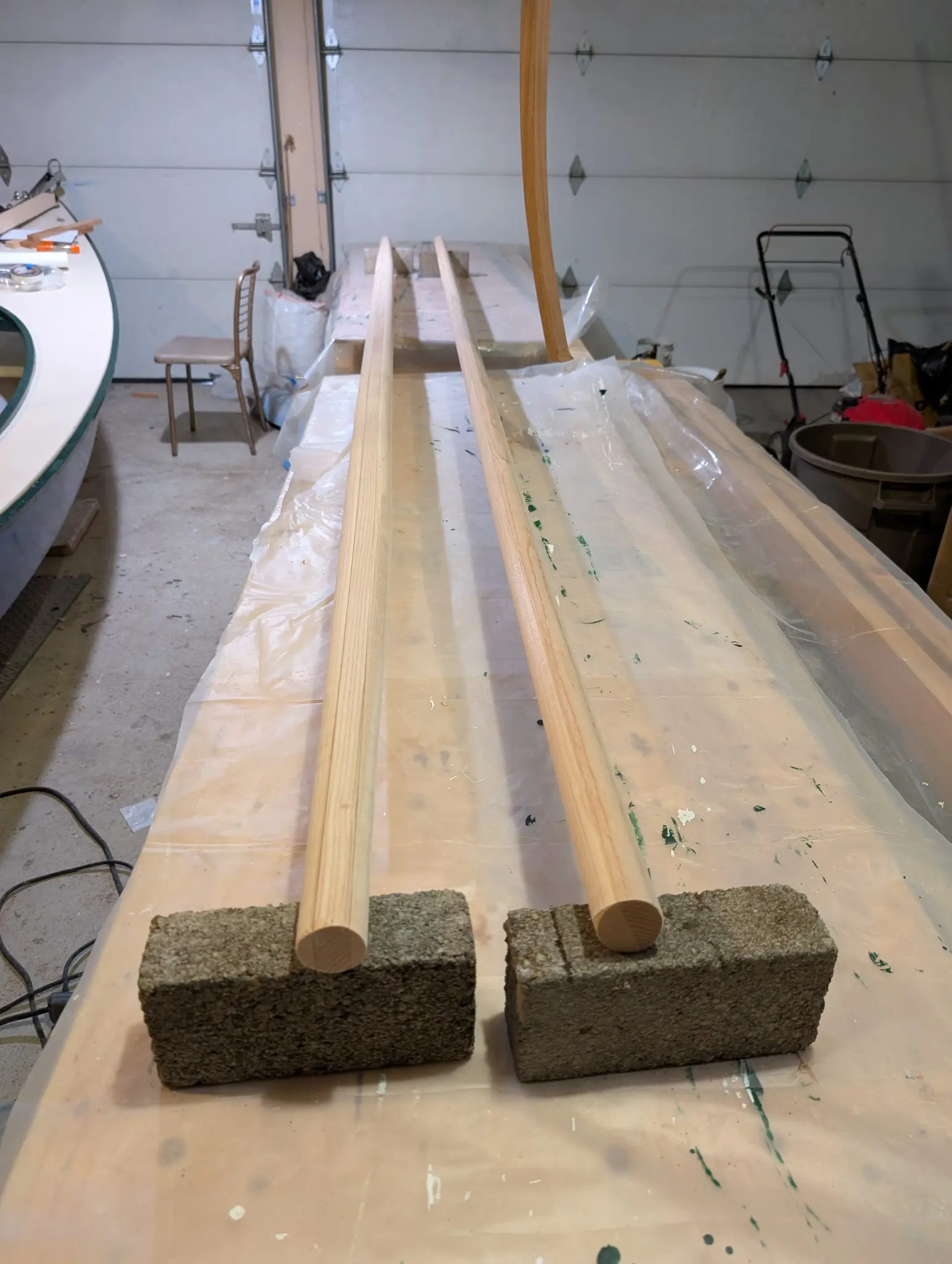
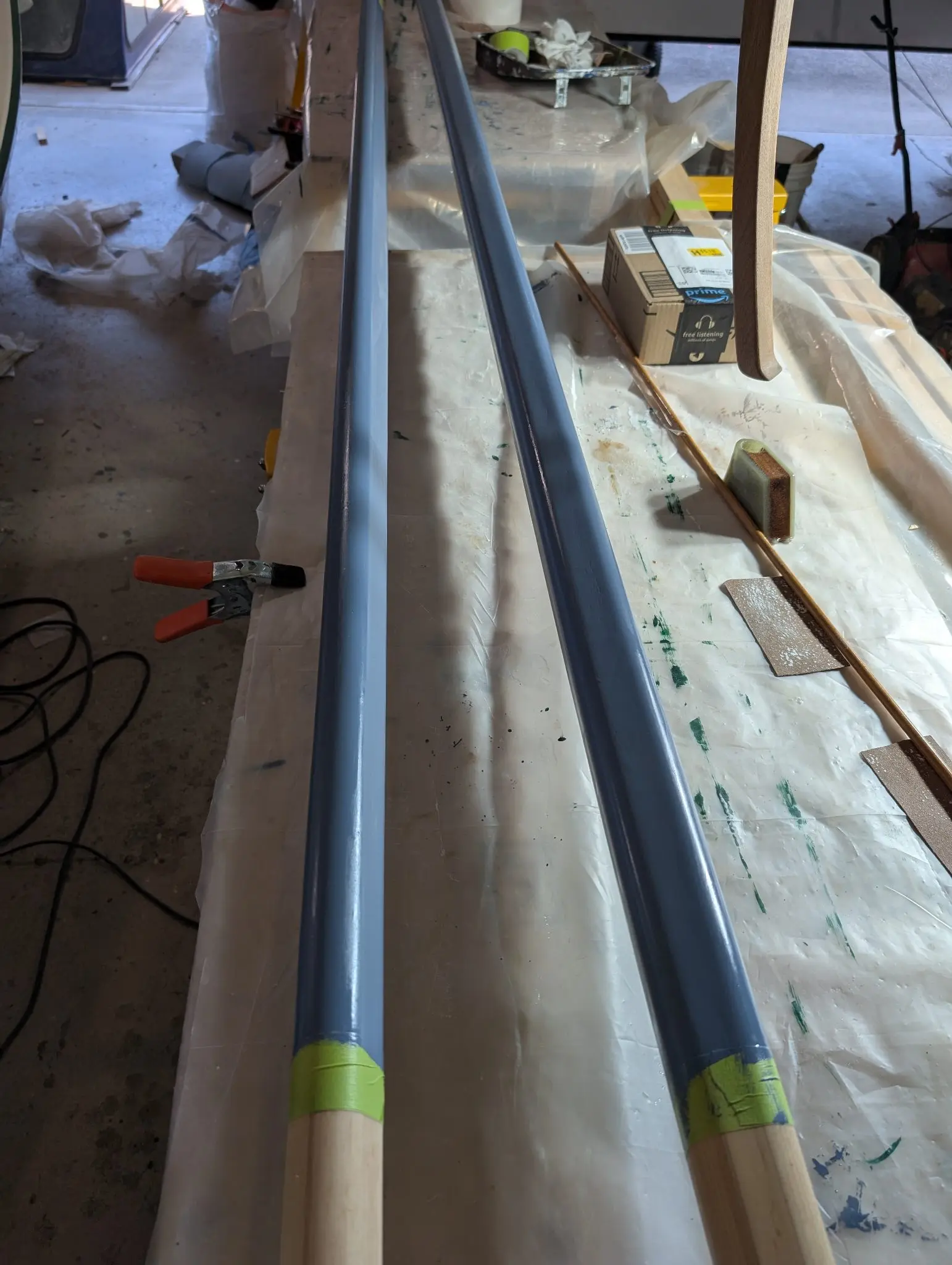
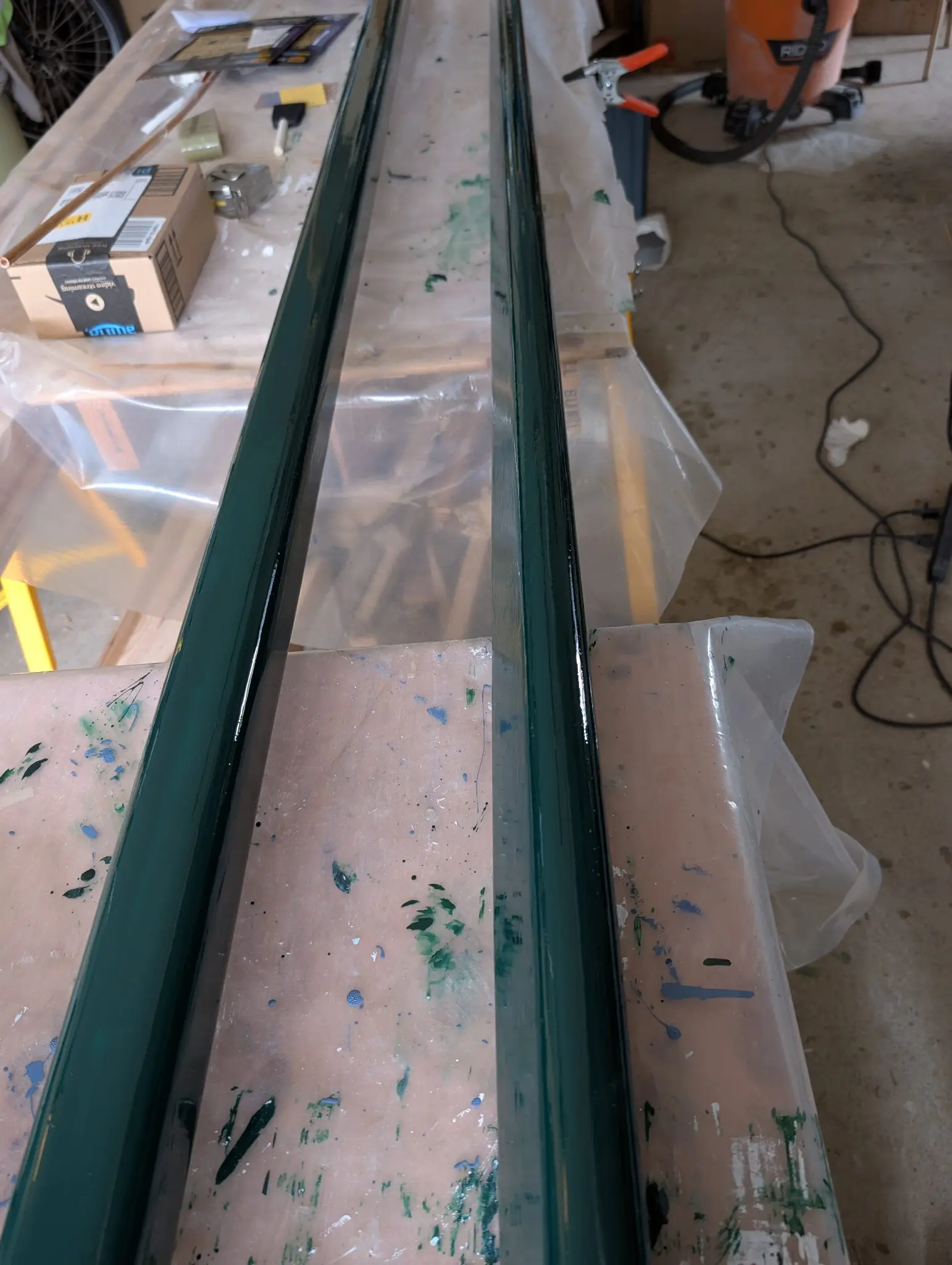
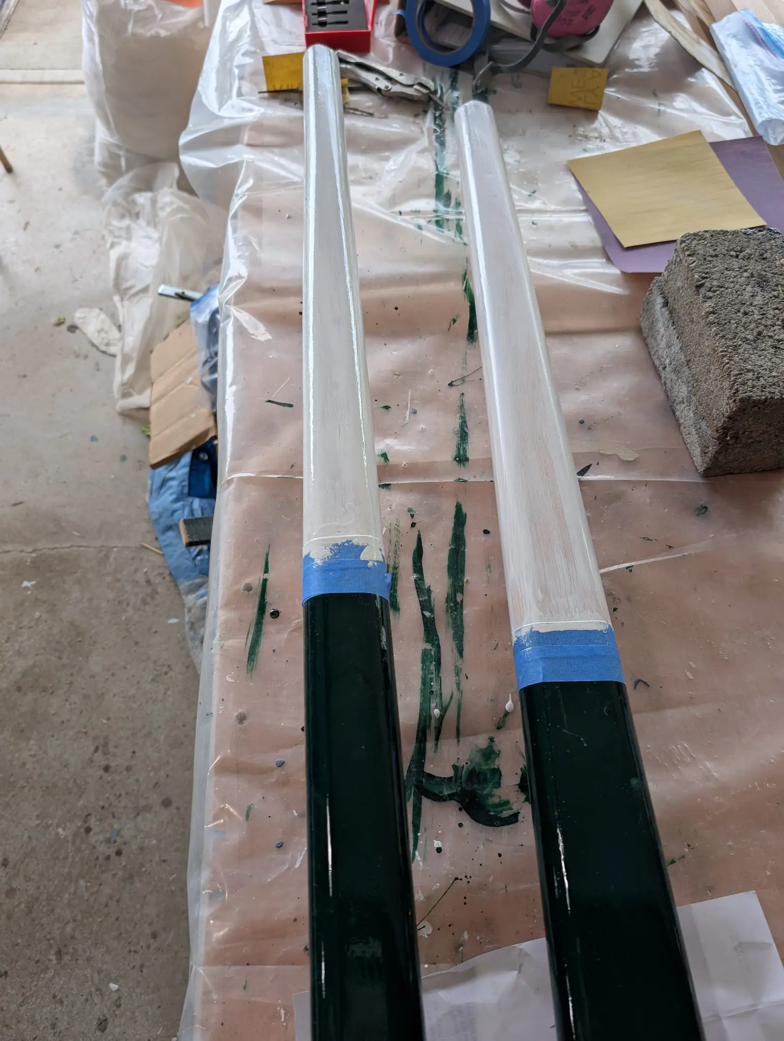
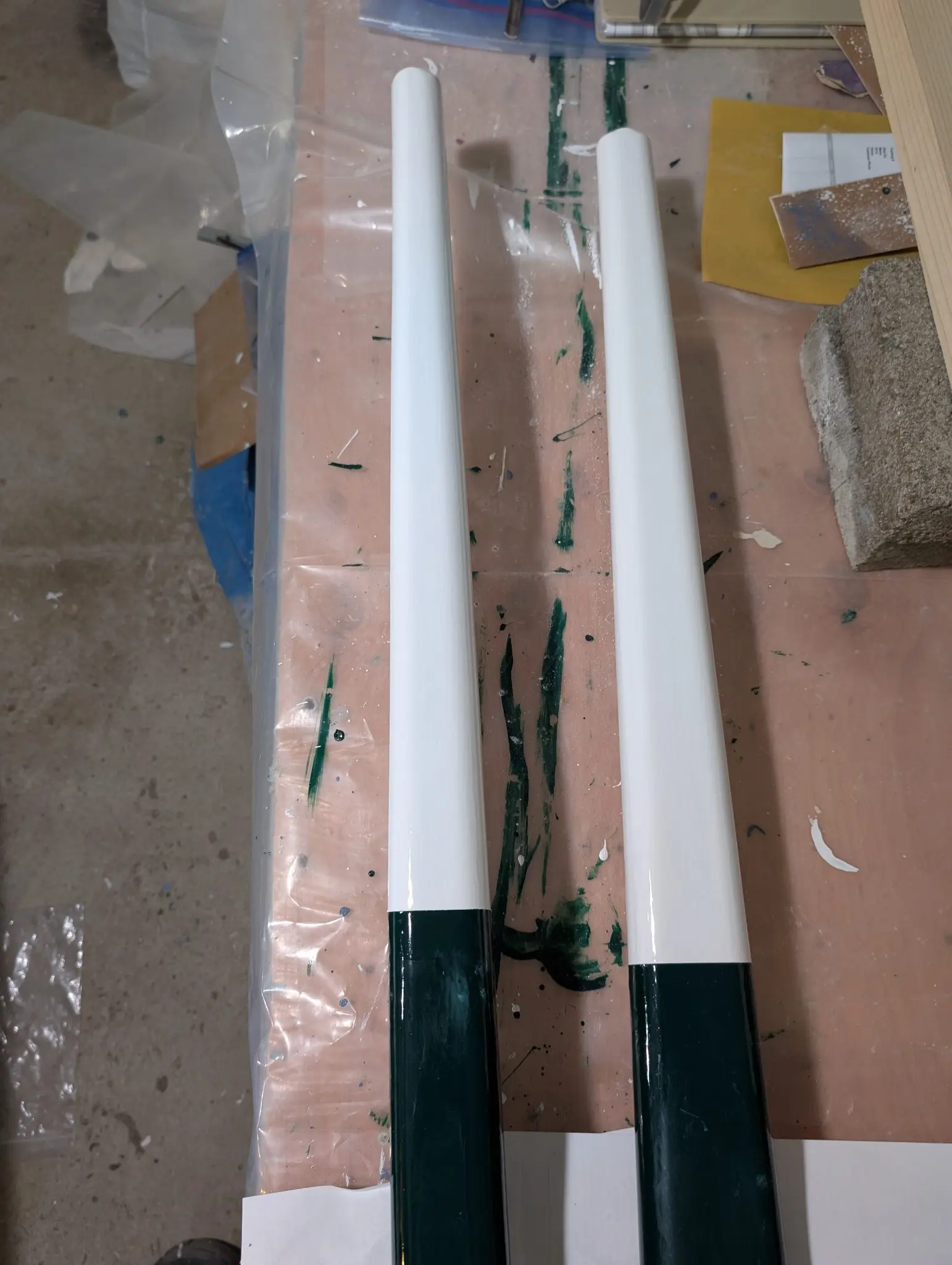
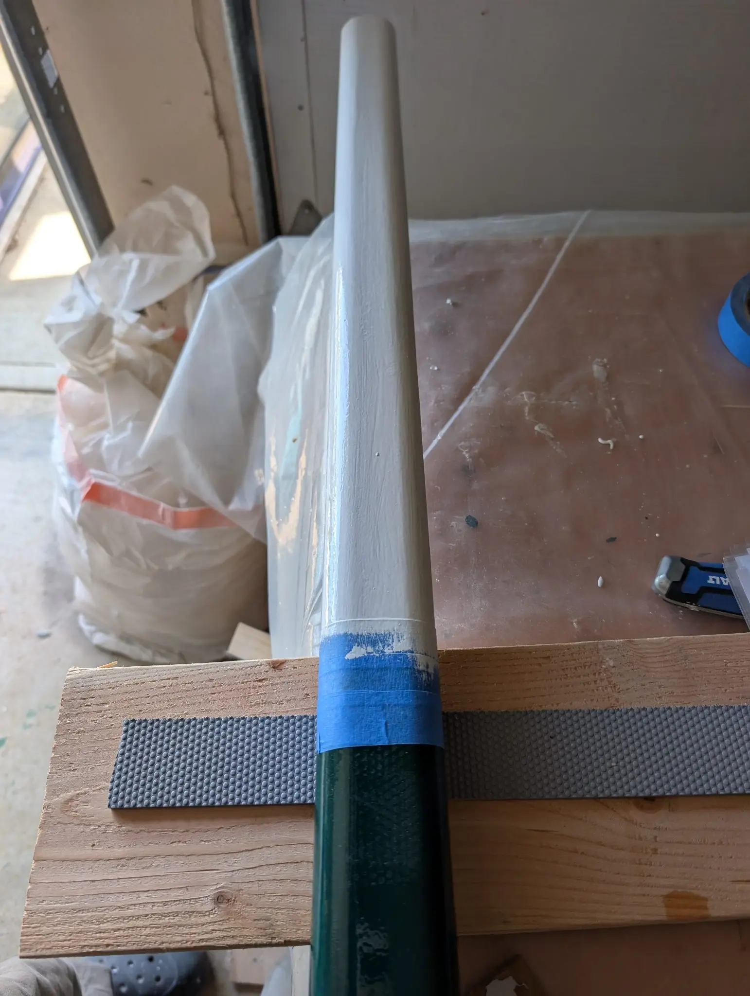
The yard and boom were sealed with two coats of epoxy, then primed and painted in two colors (Donegal Green and Mediterranean White). Where I grew up, this was a common color scheme for boats that weren't playthings for the rich and famous. I always liked the way it looked. I switched to the darker Interlux primer in the hope I could get full paint coverage with fewer coats. I almost could get away with 2 coats of paint, but in the end needed 3, just like everywhere else.
Photo 1 Photo 2 Photo 3 Photo 4 Photo 5
7 Nov 2025Rig & Spars
Build the mast yourself, they said. It'll be easy, they said.
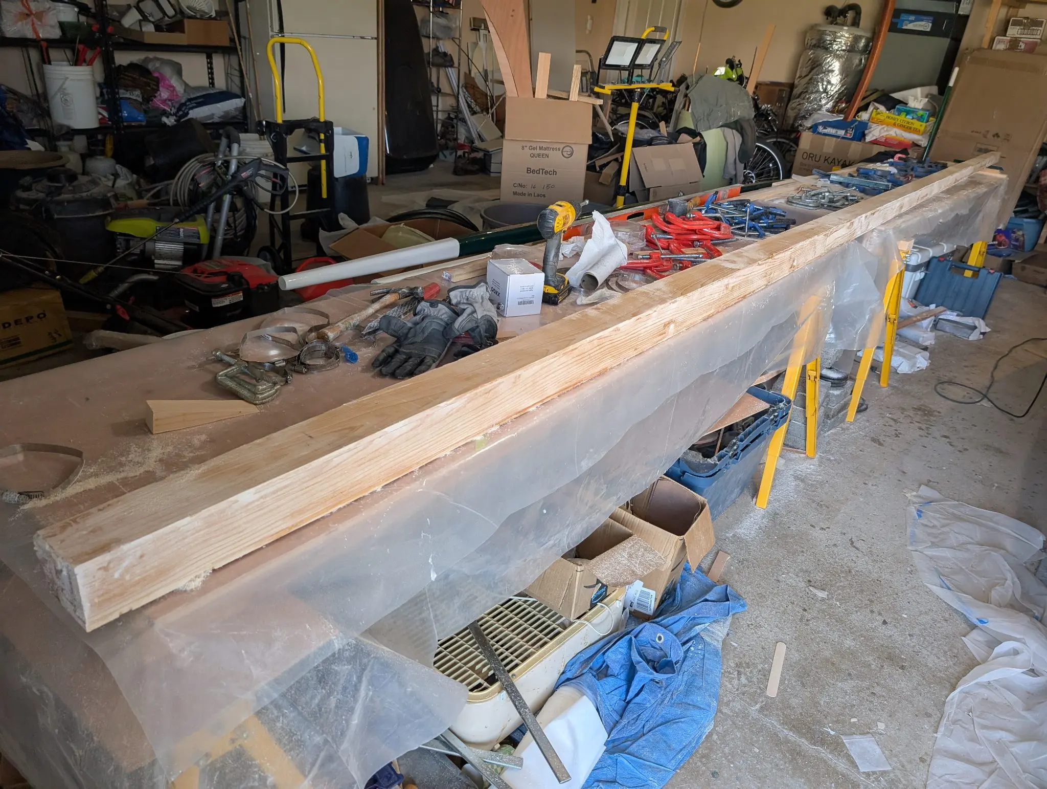
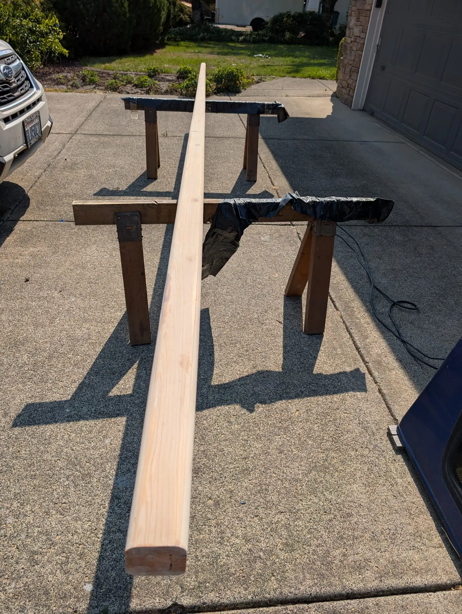
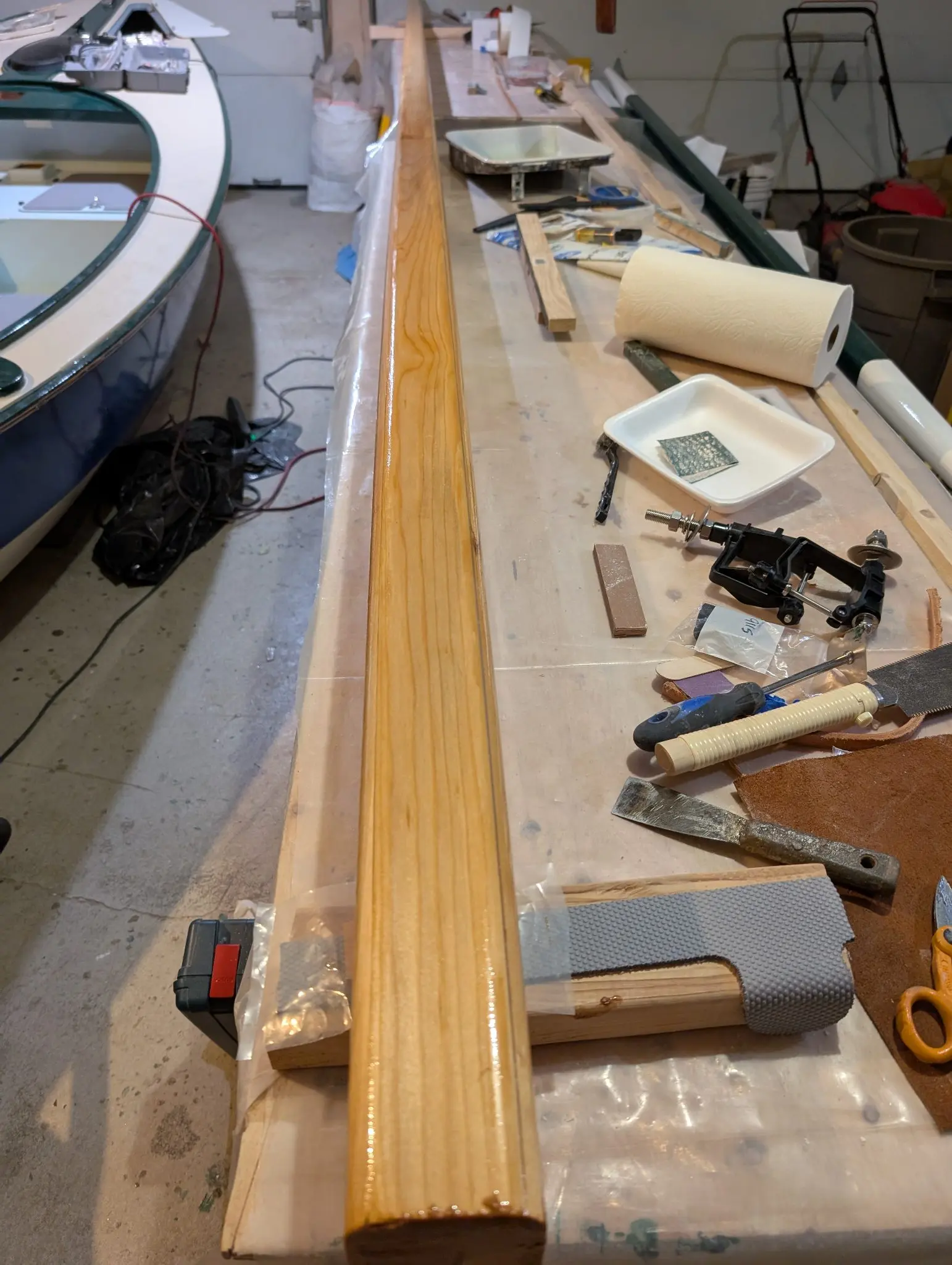
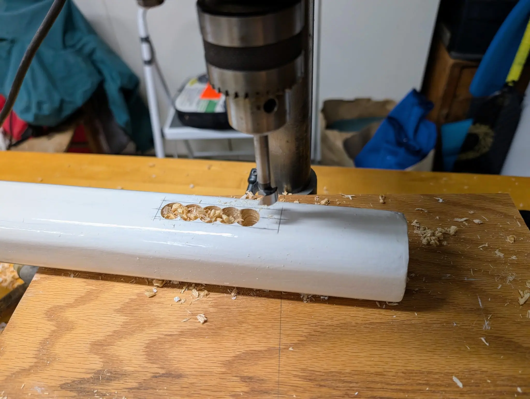
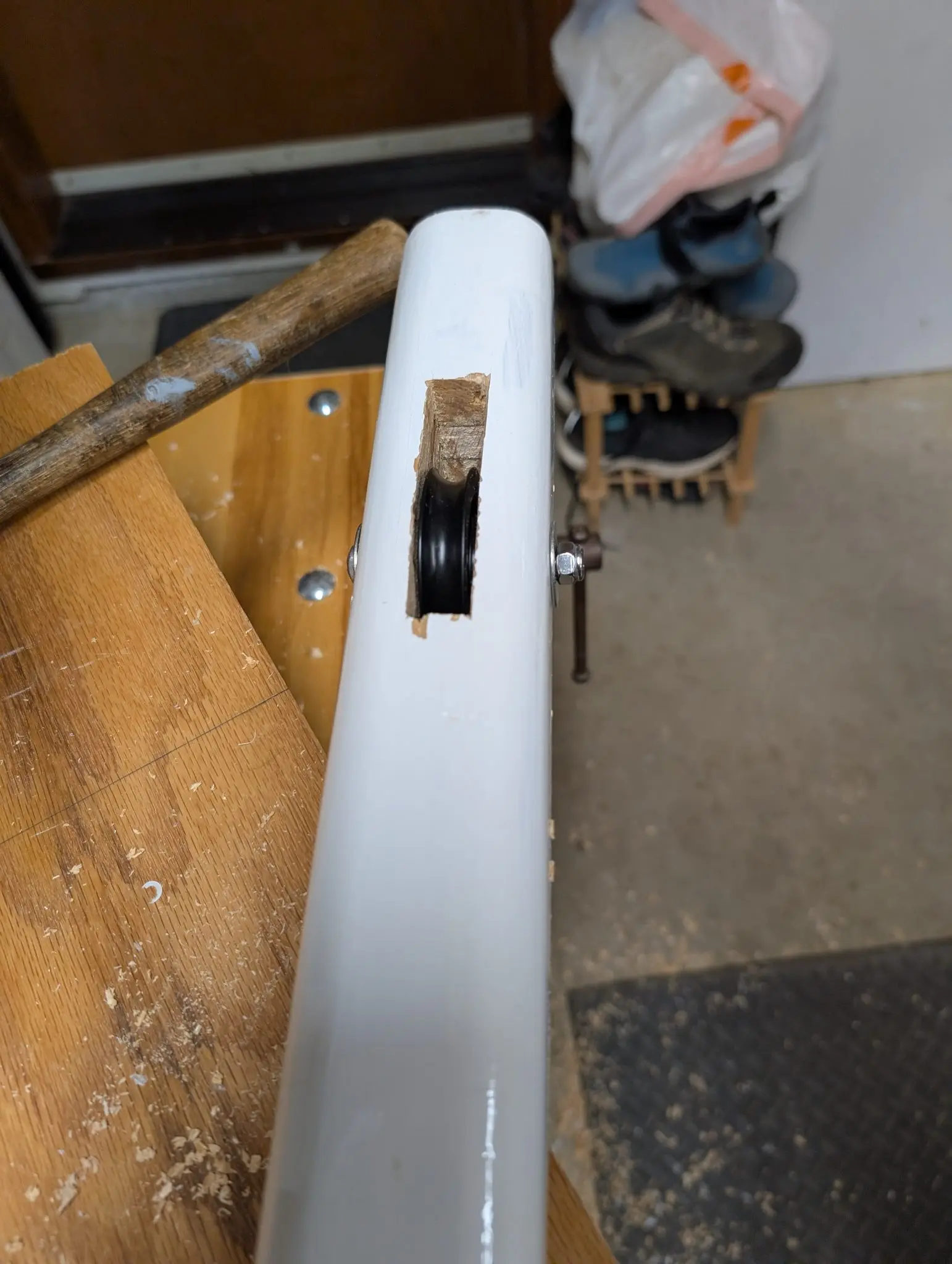
The 17' mast on Kembali is a hollow box with solid plugs on either end. The staves are scarfed from 3 pieces of solid timber, into which the tapers are cut from templates supplied by CLC. Then 3/4" rabbets are cut into both interior sides of the front and back staves. The side staves are glued into these rabbets, and the solid end plugs are emplaced during final assembly. Finally, all four edges of the mast blank are rounded over with a router, and a slot is cut in the peak to accept the halyard sheave. It's all incredibly easy to do....not. There are a lot of pictures here showing
most of the steps.
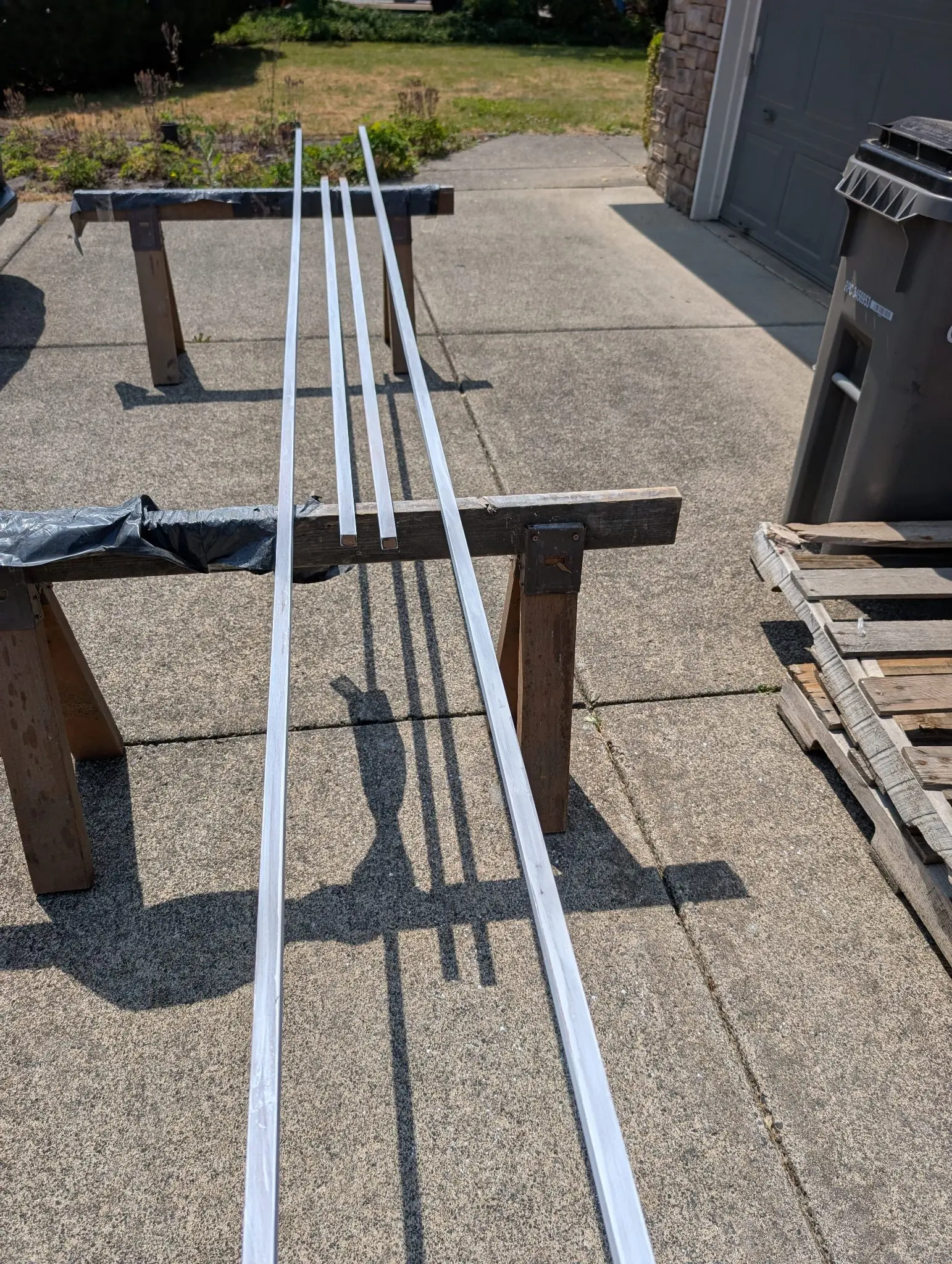
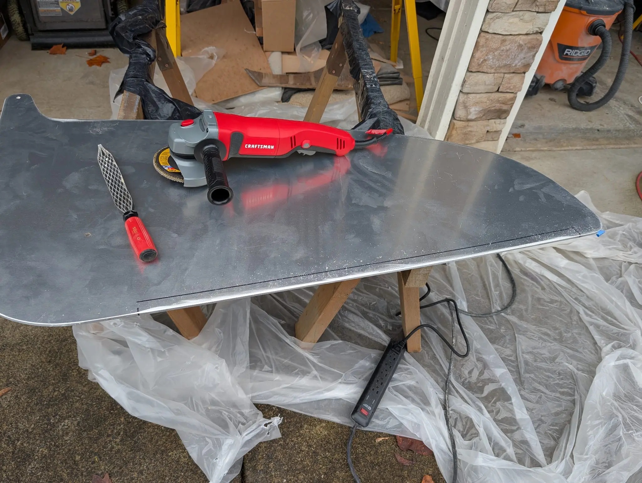
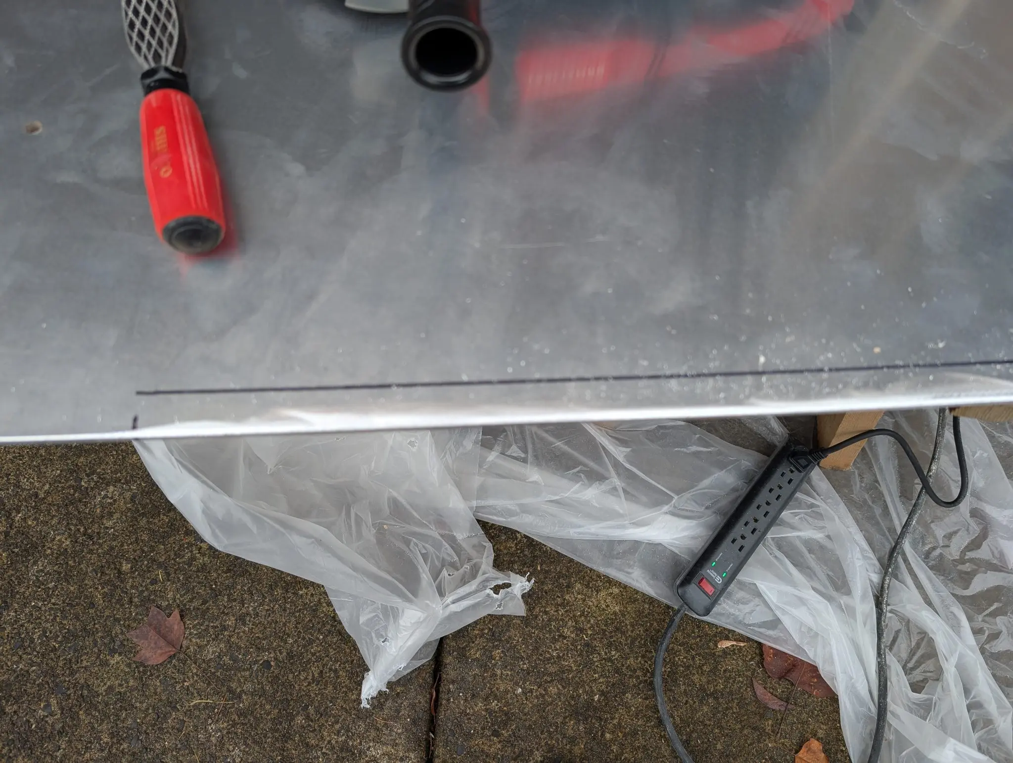
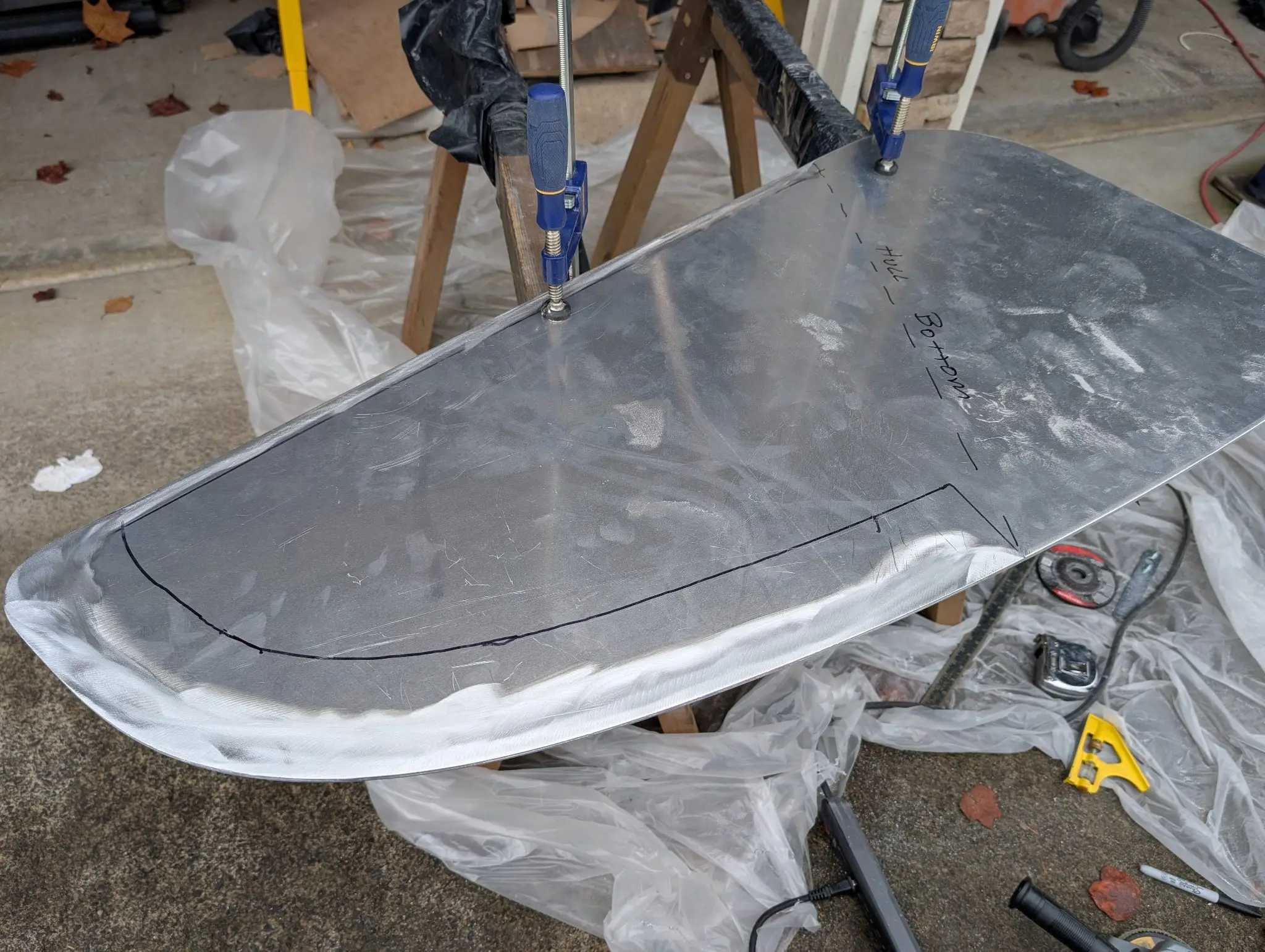
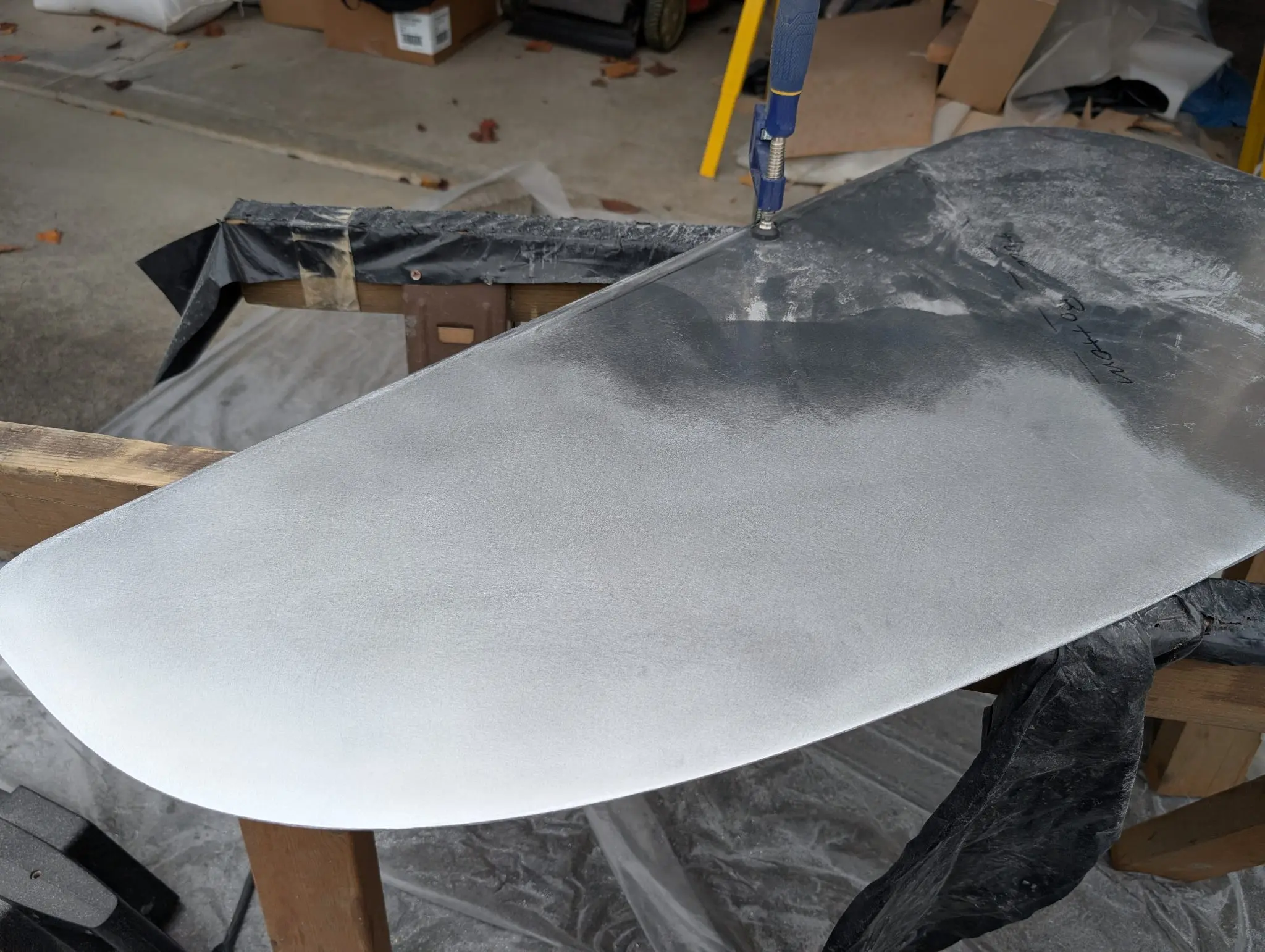
CLC supplies a 1/4" thick Aluminum centerboard blank, cut to shape, with a pre-drilled pivot hole. The build manual lays out how the tapers should be done to give the centerboard the proper hydrodynamics. The only problem was I had no clue how to work the aluminum. I tried to find a machine shop to do it, but it was too small a job and had too long a lead time. I ended up doing it myself with a cheap angle grinder (which died), a shinto rasp (an amazing tool), files, and a random orbital sander. I took the surface to 600 grit to make it nice and smooth. Elapsed time on the job was about 6 hours, spread over two days.
Photo 1 Photo 2 Photo 3 Photo 4
14 Jan 2026Hardware & Fit-Out
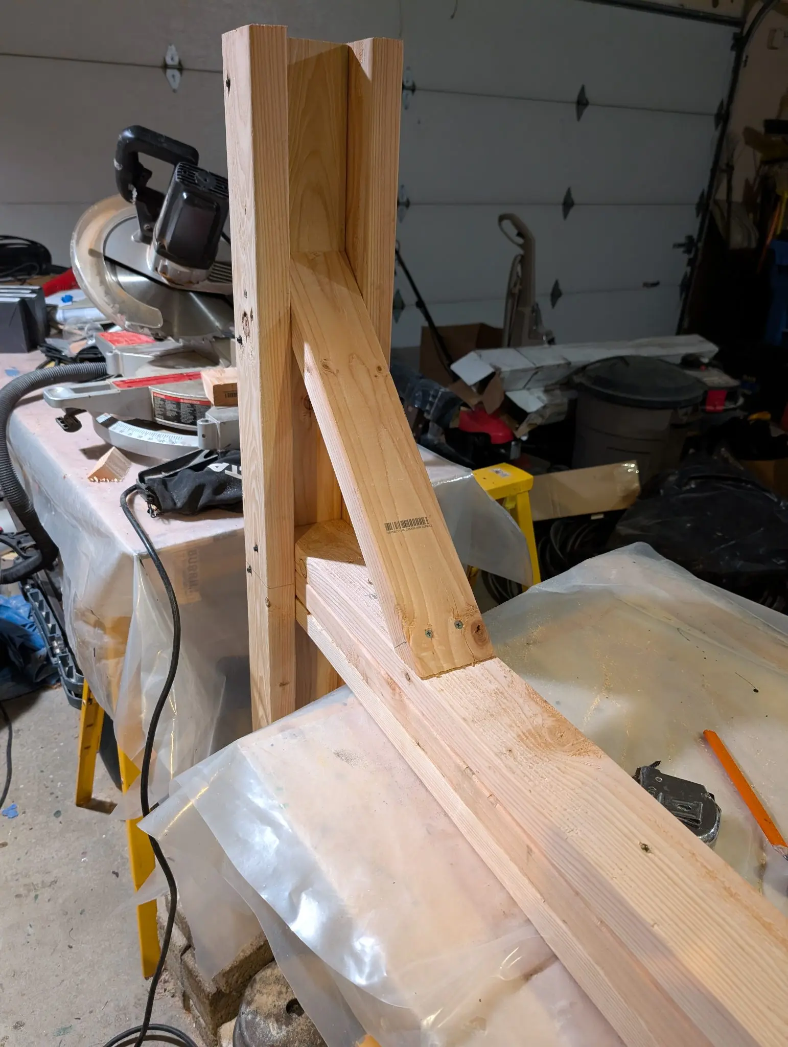
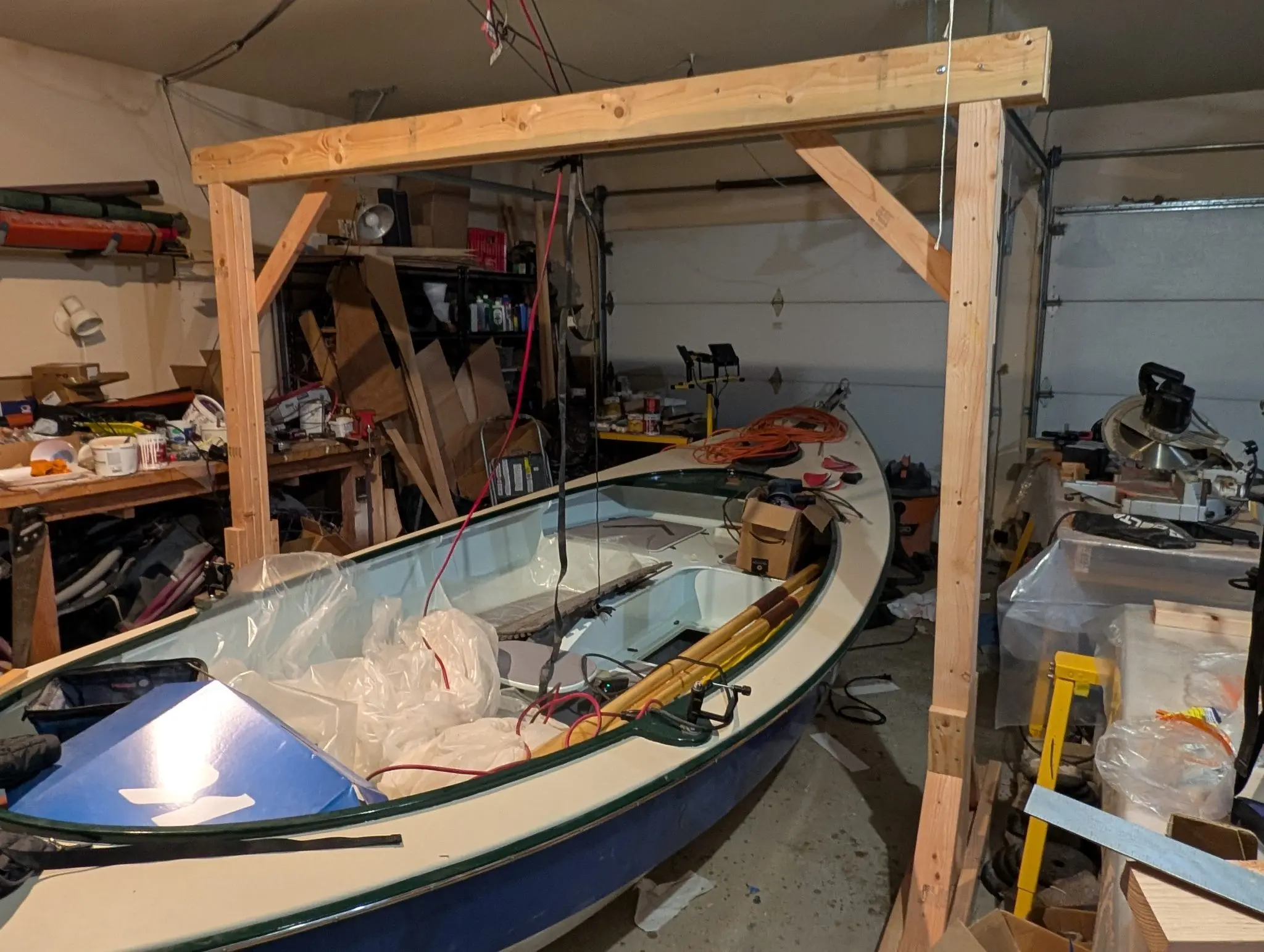
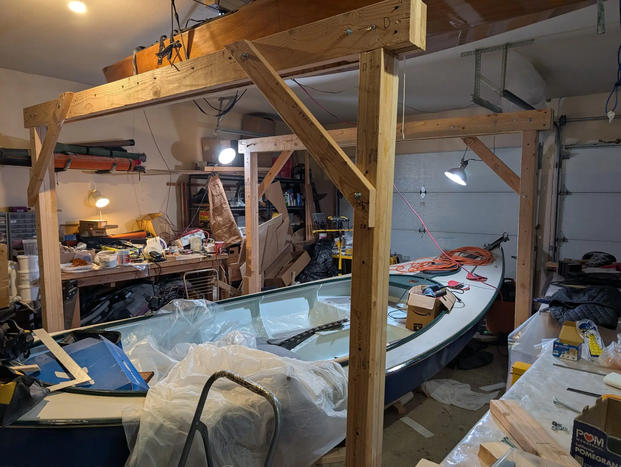
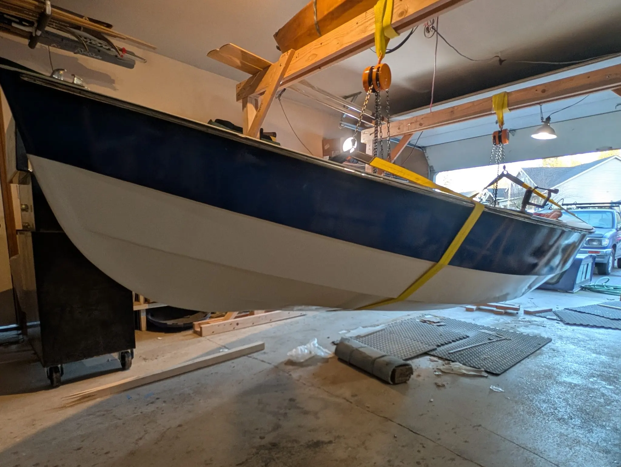
Building gantries. It flies!
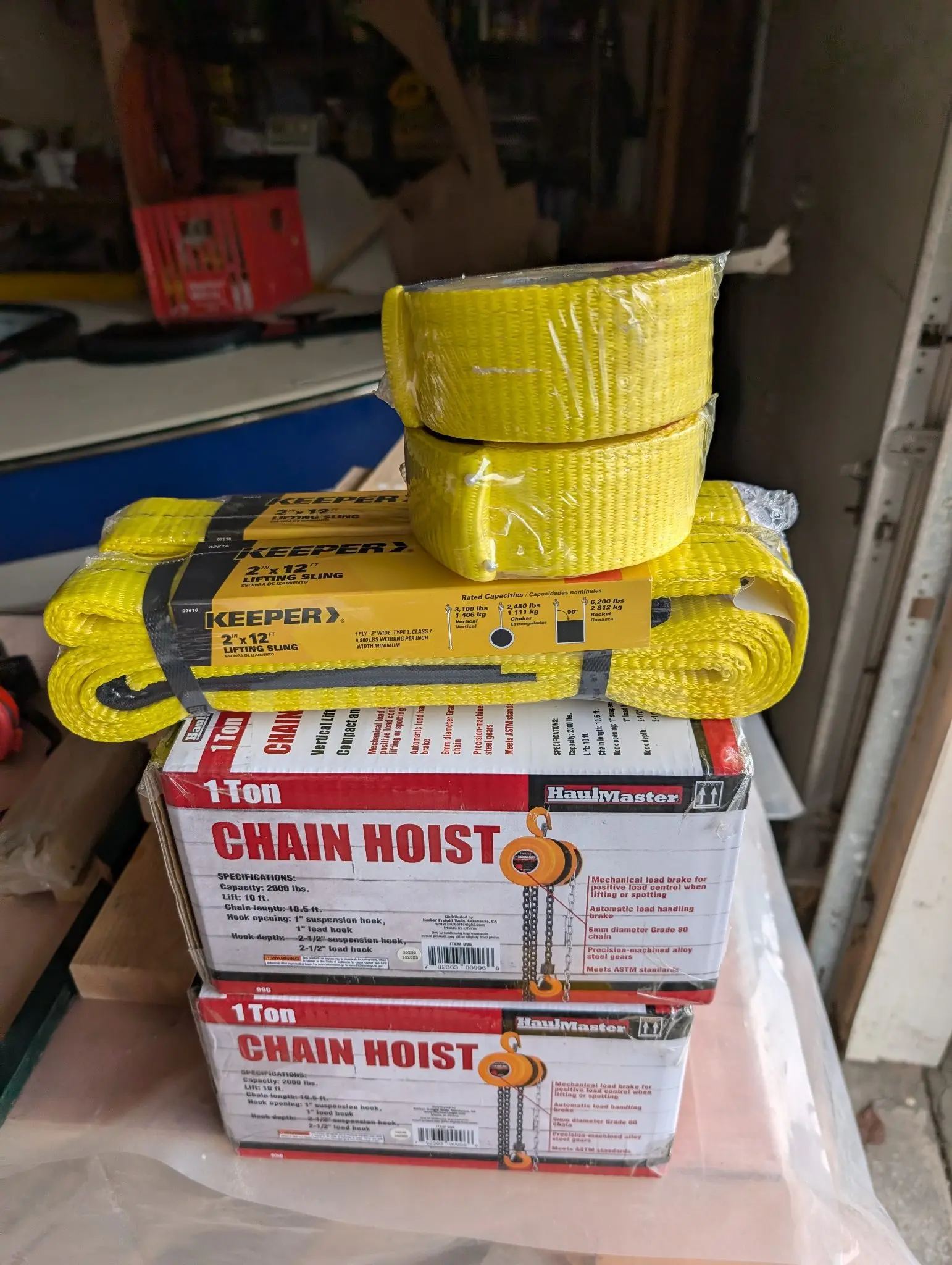
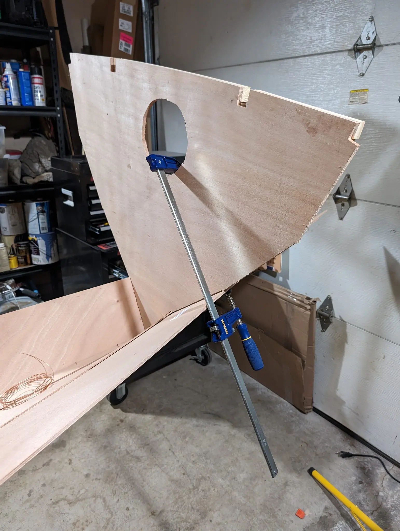
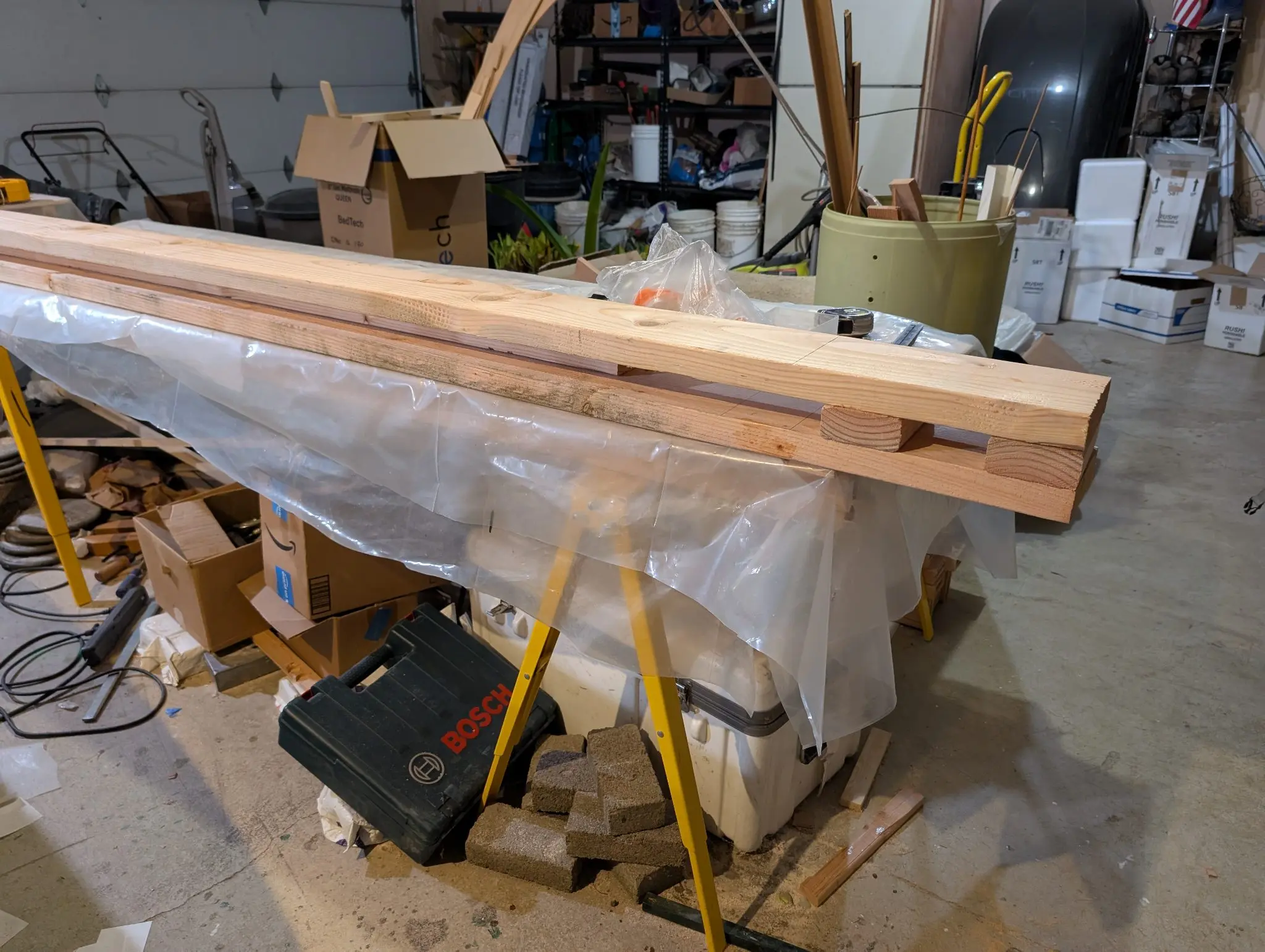
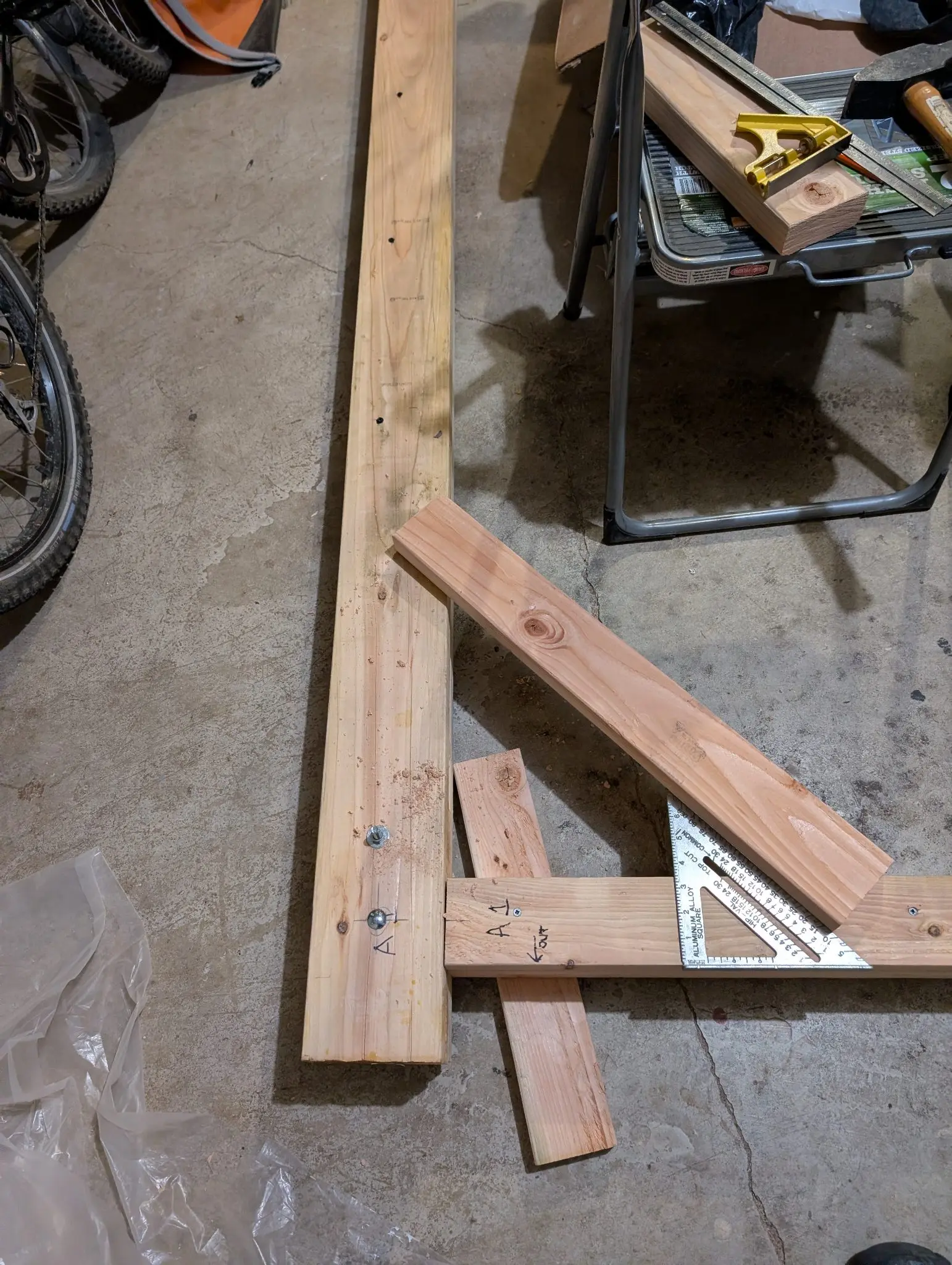
The CLC build manual says the centerboard should slide into place from above. Either I did something wrong in construction, or they were dreaming. There was no way it was going in from above. I thought about what to do for a long time. Early in the build, I had friends over for flipping parties, but at this stage of the build it was a very different flip. The hull now weighed 500-600 lbs, and it would have to be carried out of the build space and rolled very carefully. I didn't like that option, so I built gantries to lift the boat and slide the centerboard in from underneath the hull. I also figured gantries would be a good way to get the boat on and off its trailer as needed. The gantries were built with construction-grade lumber from Home Despot and fitted with chain hoists and webbing from Harbor Freight. In the end, they were a success. At this point I had no idea if the boat would float but it definitely could fly!