Frames
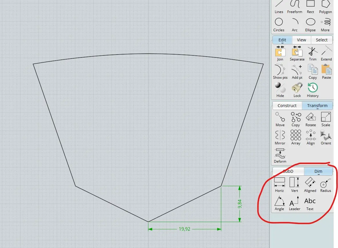
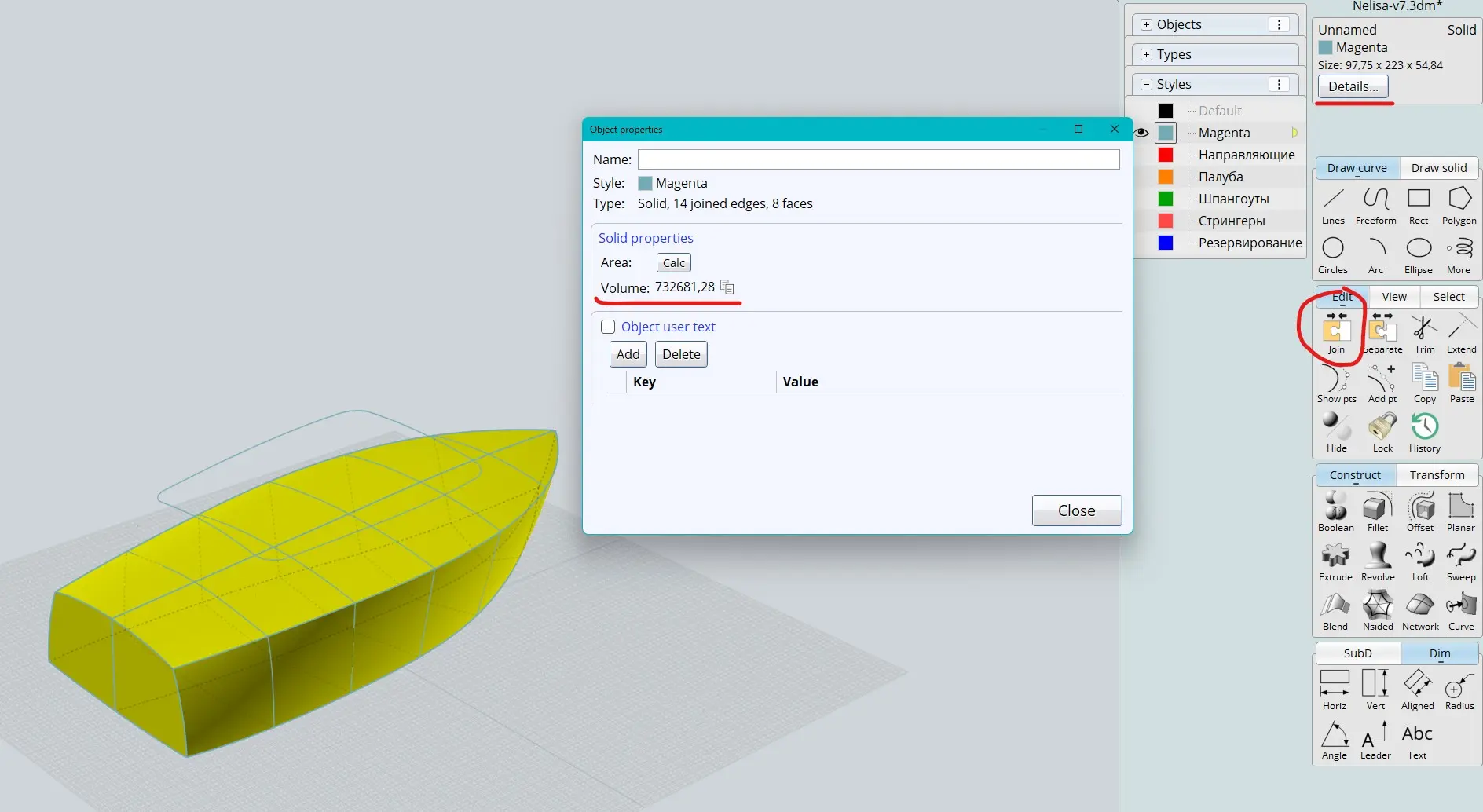
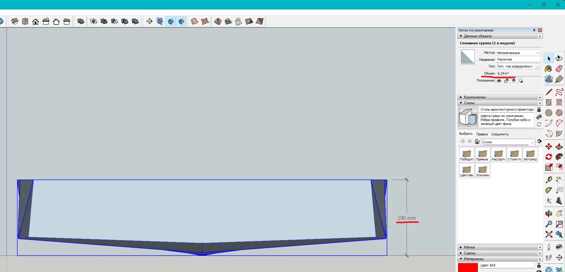
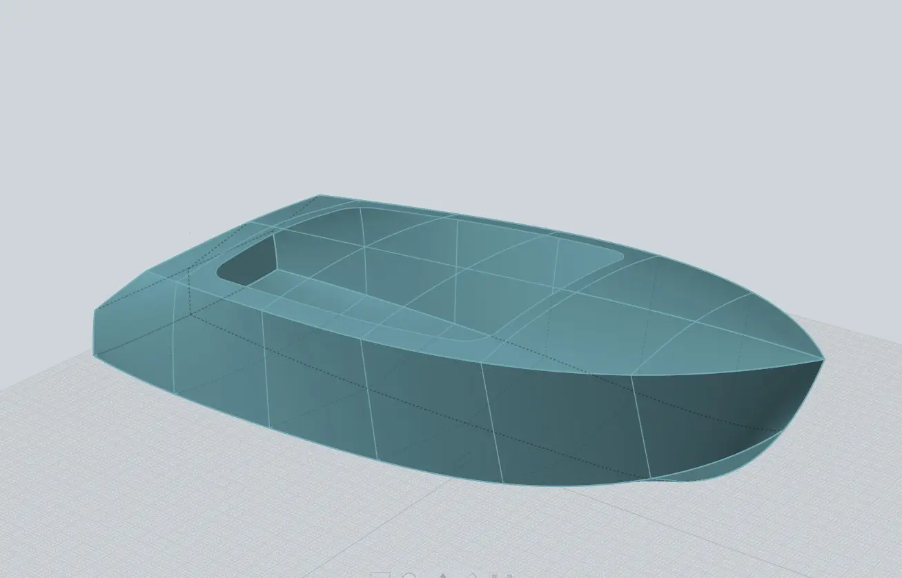
An update on the Moi3D software: I’ve discovered how to calculate curve lengths and the volume of shapes, as well as how to add dimensions. The program contains everything necessary for basic boat design.
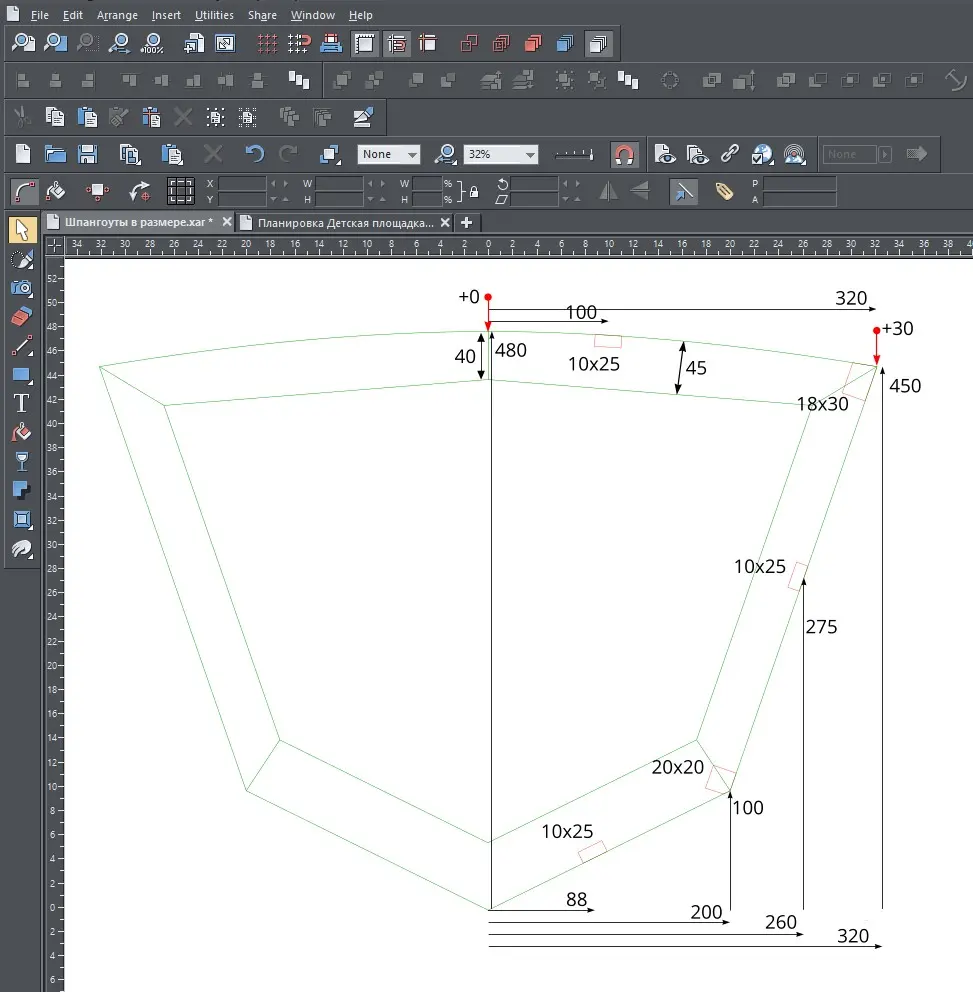
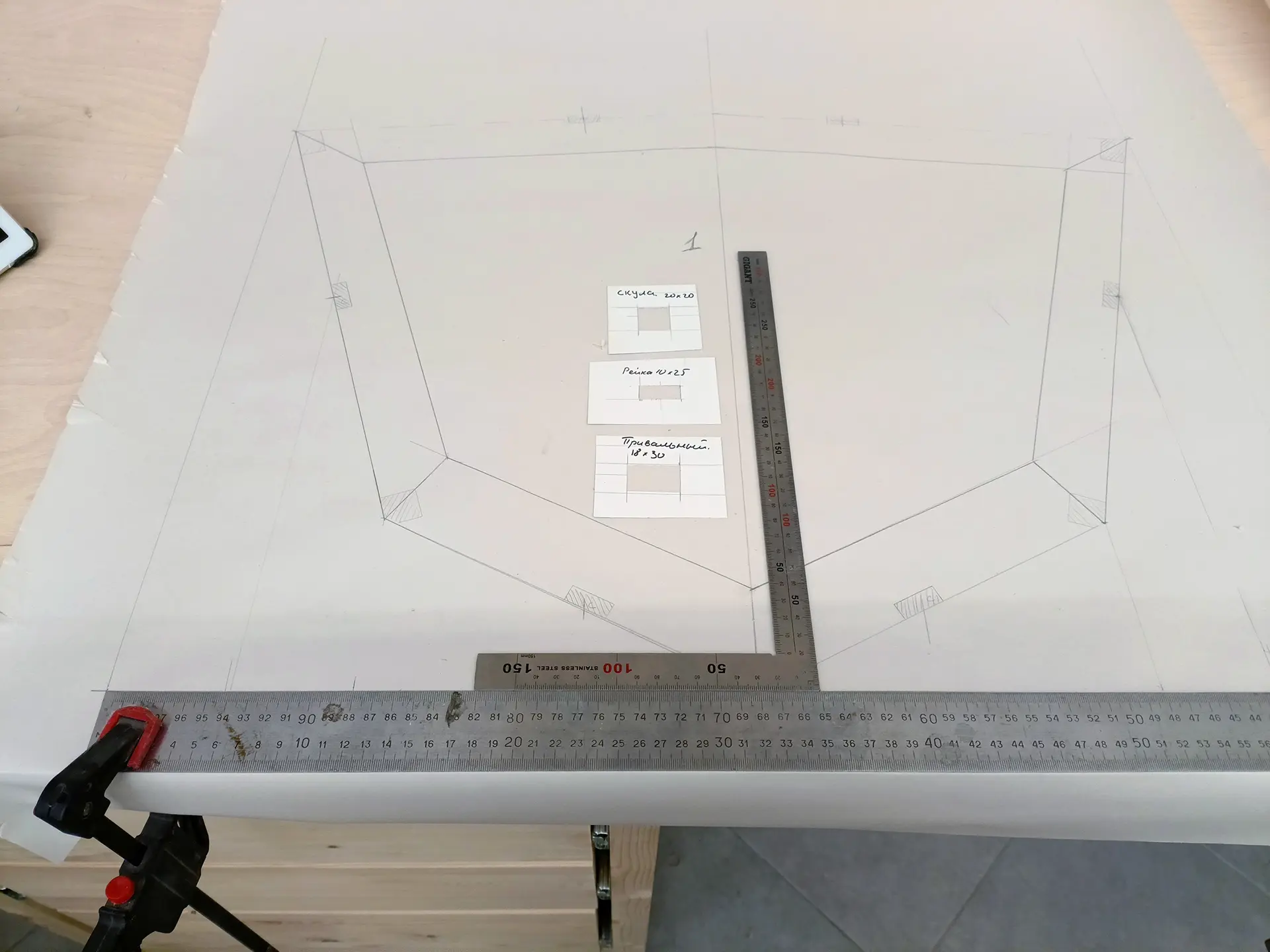
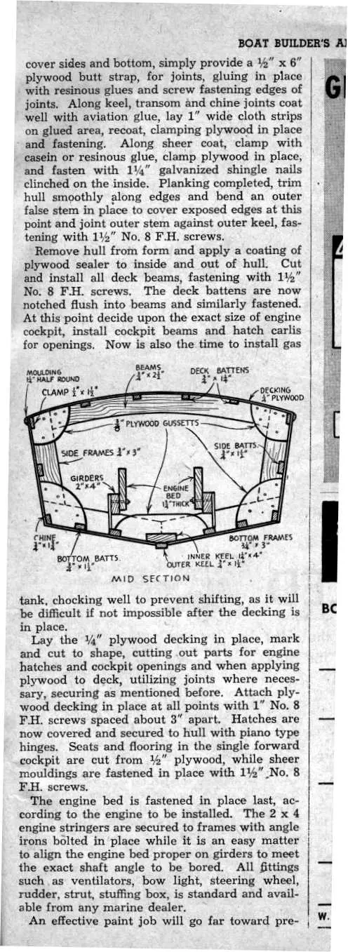
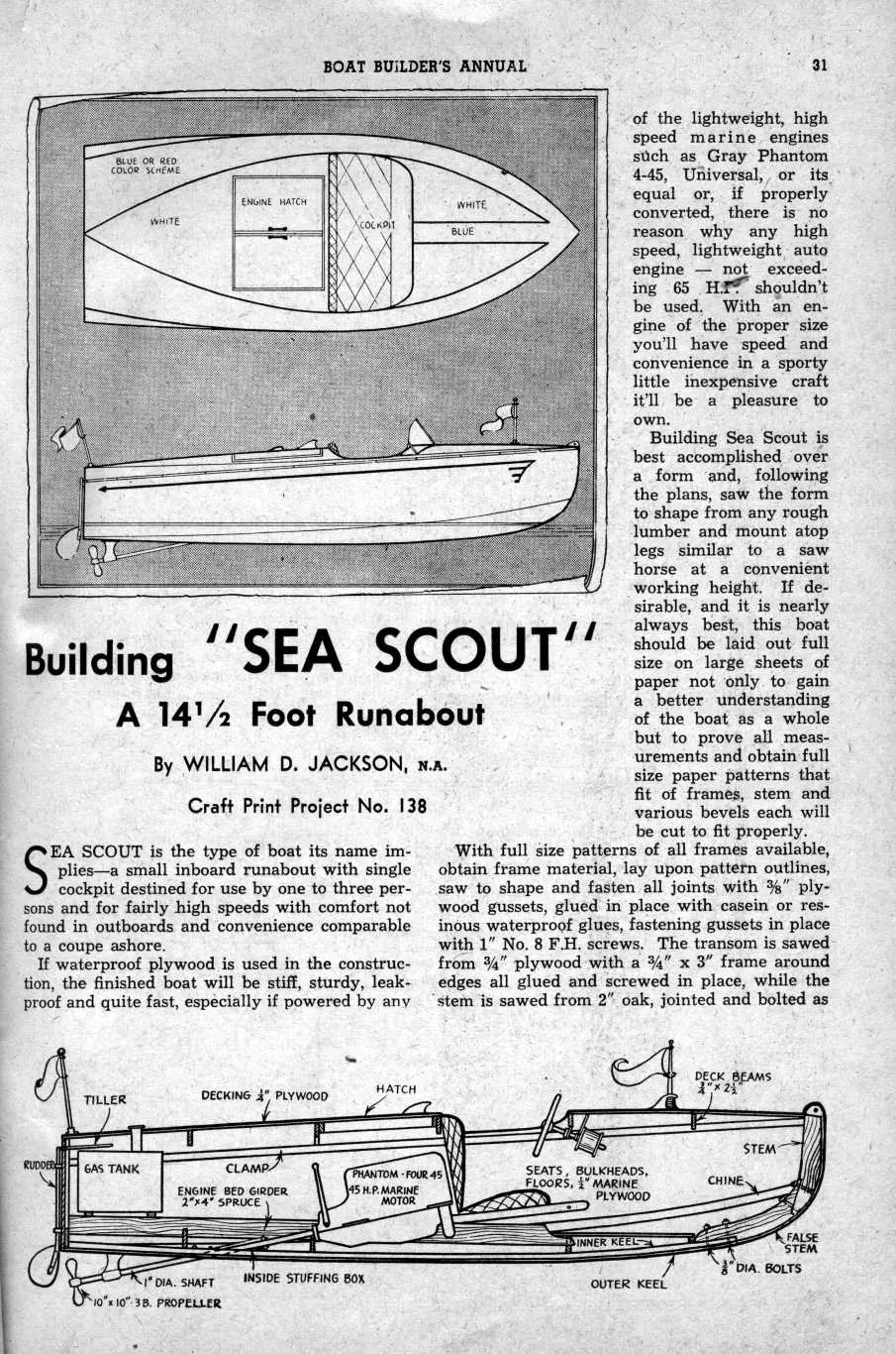
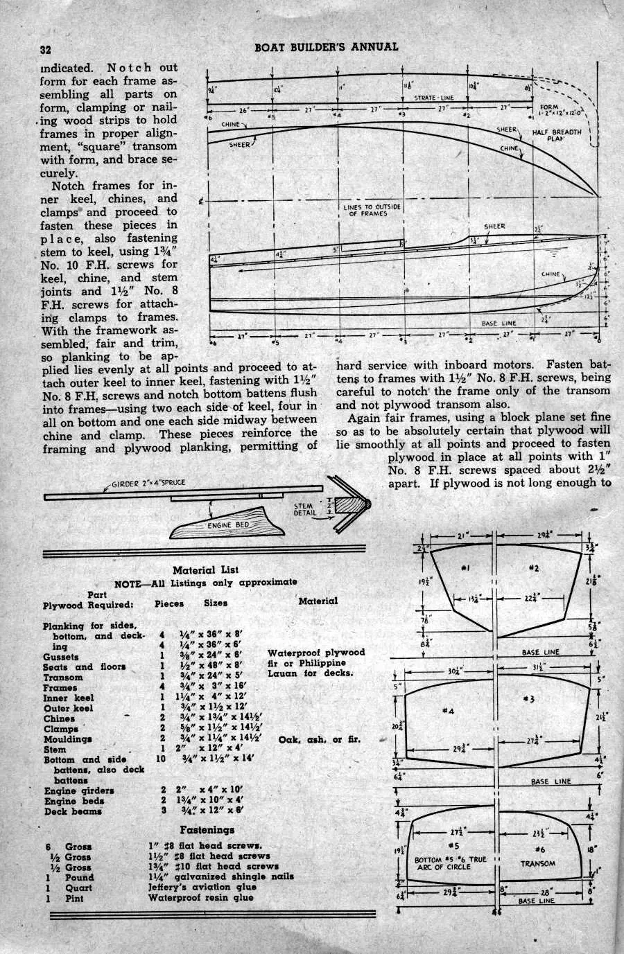
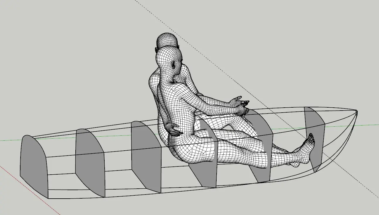
I finished building a desk for a friend and converted it into a drafting table before she could clutter it up with her belongings. The next step was to draw all the frames at full scale. I came up with the idea of attaching a one-meter ruler to the bottom of the drawing surface, which allows me to rest a set square against it—this makes the drafting process both accurate and fast. It’s especially convenient if the ruler has its zero point in the middle. I used metal rulers of three different lengths and a pair of set squares. I also created templates for the cross-sections of the stringers and the keel to speed up the marking process, and I made a template for the deck camber out of thick cardboard. I fabricate the individual components of each frame in pairs. This ensures precision and even helped me spot two errors in the original design. I cut the angles using a miter saw; an accuracy of 0.5 degrees is sufficient to replicate the drawings.
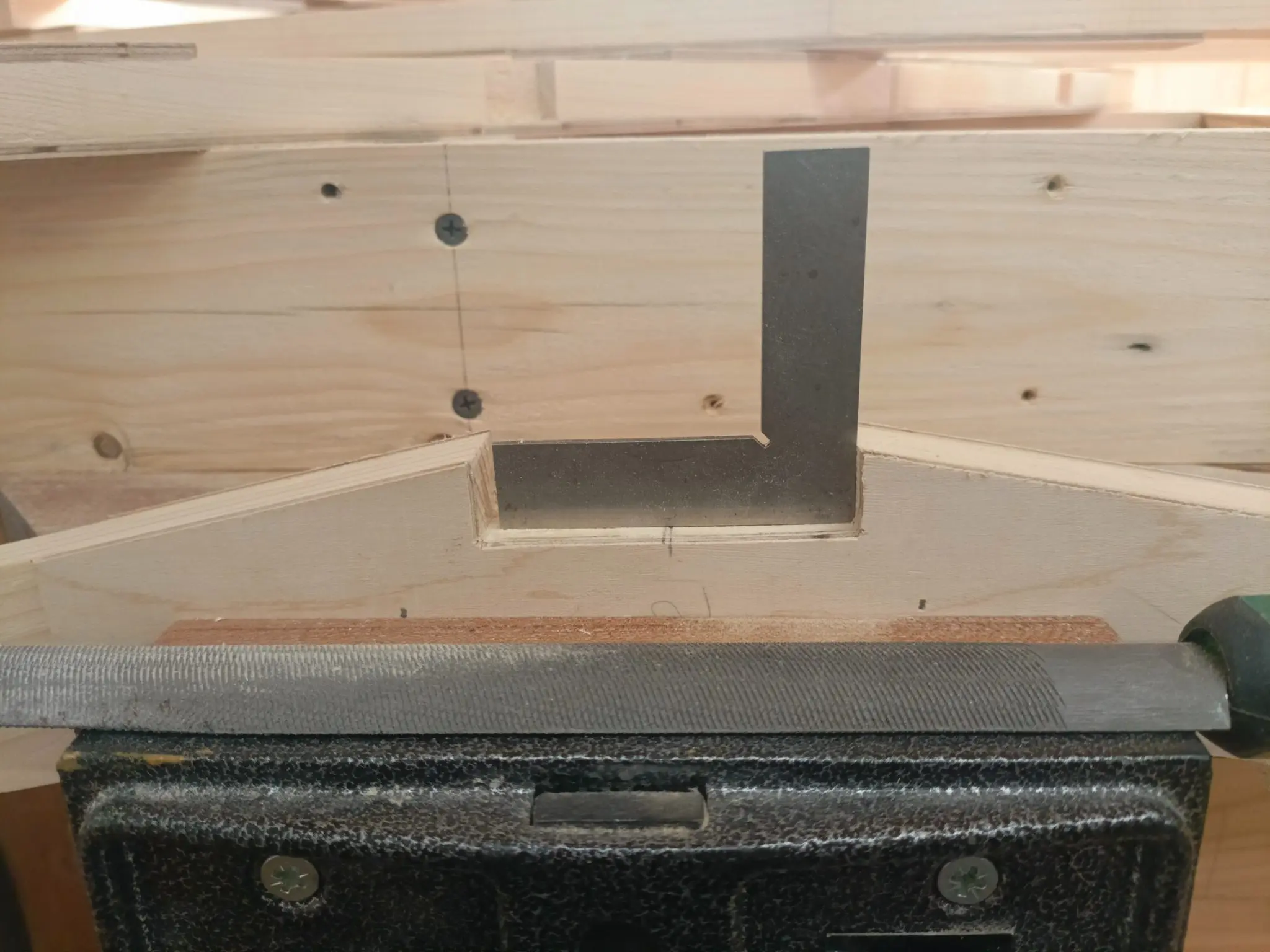
I cut the notches for the keel, leaving about 1 mm of extra material. Once the frames were glued together, I refined the notches using a rasp. Alternatively, you could stack all the frames together and process all the notches at once. It’s best not to cut other types of notches at this stage, as their depth and exact position on the frame may differ from what is shown on a flat, two-dimensional drawing.
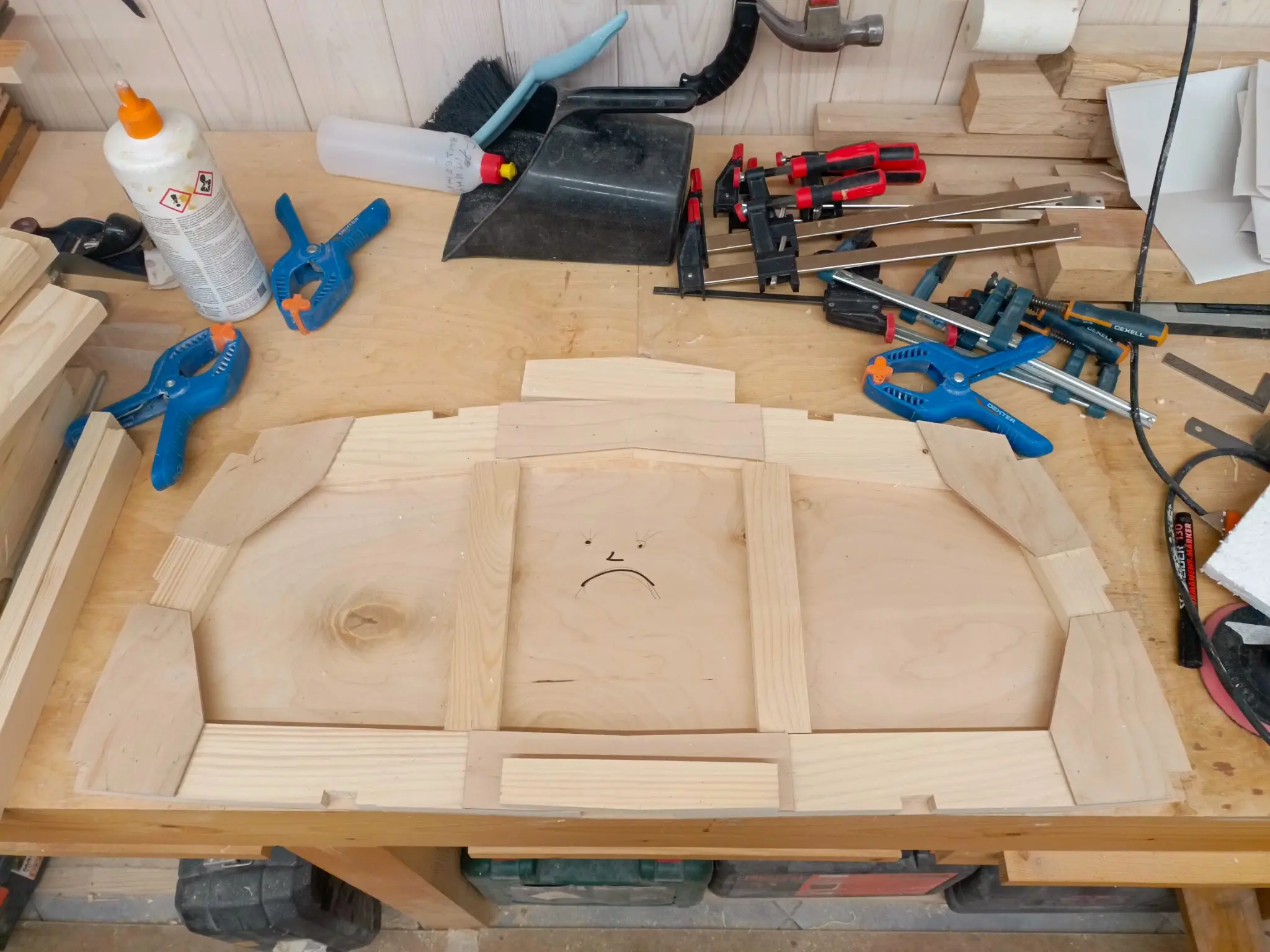
I make the gussets (knees) out of 4 mm moisture-resistant plywood, taking the dimensions from a shipbuilding reference manual. The gussets are secured using both glue and screws. I even bought screws, but I decided to check whether it’s possible to build a boat without them—after all, 100 years have passed since those textbooks were written, and adhesive formulations have evolved. PUR 501 glue seems so strong to me that using screws in plywood feels pointless. Incidentally, it is certified for marine construction. To keep a knee (gusset) from shifting after applying the glue, I secure it with two or four thin nails. I also place a piece of polyethylene under the joint to prevent the glue from staining the blueprints. I then clamp the knees in place, as required by the glue’s instructions.
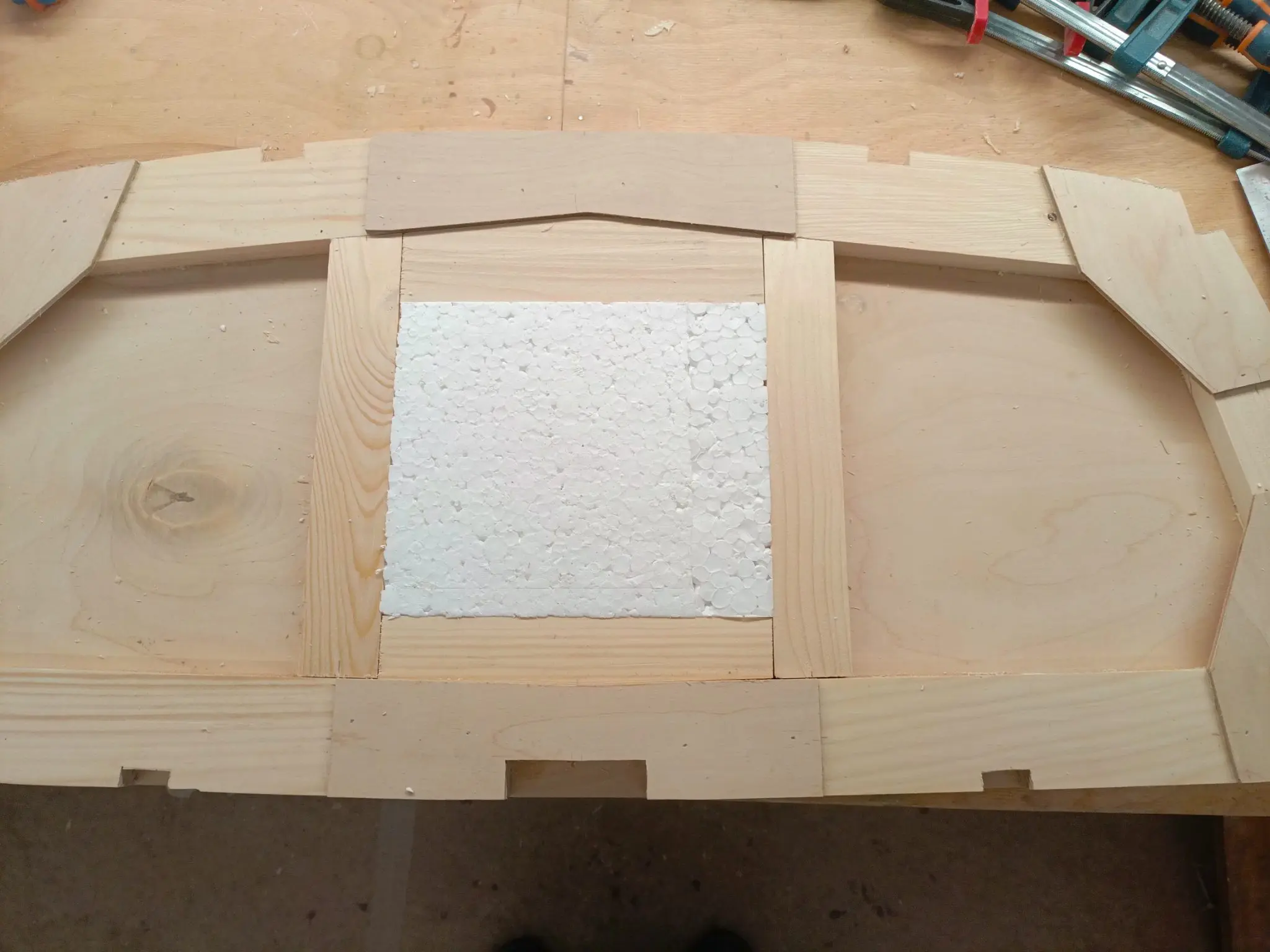
The boat’s transom is assembled differently. First, I glue the knees onto one side. Then, I cut out the notches for all the stringers, followed by gluing on the transom plywood. Next, I trim the transom using a pattern-following router bit—though I have to be careful to ensure that the stringer notches aren't cut into this particular layer of plywood. During the design phase, I failed to include a transom framework for mounting an electric motor—an oversight on my part. I had to add this framework later, which is, of course, not the ideal way to do it. Therefore, before gluing the transom, it’s important to remember that its construction differs significantly from that of the other frames (bulkheads). The voids between the plywood layers are filled with foam to reduce the air volume where condensation might otherwise form. That said, it’s worth noting that expanded polystyrene (EPS) is actually hygroscopic—unlike extruded polystyrene (XPS).
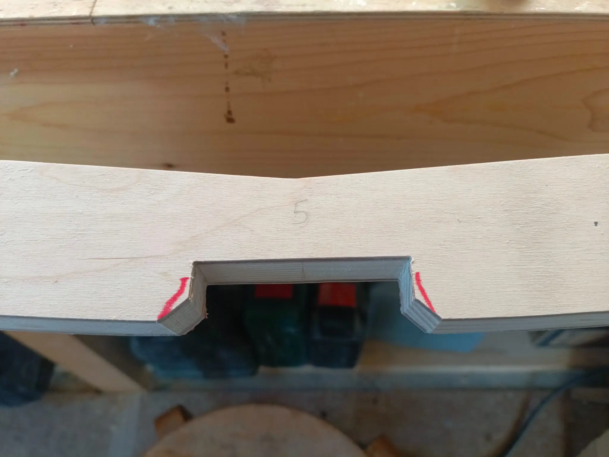
The first and fifth frames feature cutouts near the keel (limber holes) to allow water to drain out of enclosed spaces should any get in.
PS: Now, as I assemble the boat’s framework, I’m realizing what changes need to be made to the design. I am currently making modifications by adding to or trimming parts of the frames. However, a second boat—should I choose to build one—would not require these adjustments.