Hot Rod · step
Systems
Electrical, plumbing, fuel, steering, pumps, nav lights.
Systems on every boat, not just the Hot Rod →
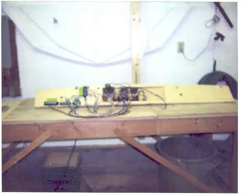
Wiring the dash.
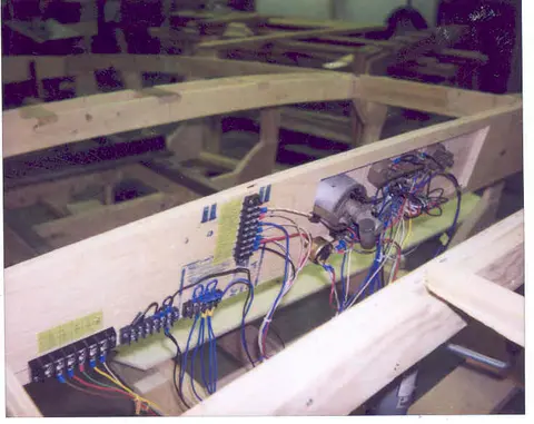
Dash installed. Hooking up temporary terminal boards. The terminal boards will be installed on a swing-out panel under the dash. The wiring is left on the long side to enable removal without undoing any wiring.
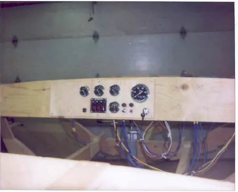
Finished dash. Time to start thinking about a steering system . . .
Dash installed. Carlings completed.
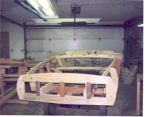
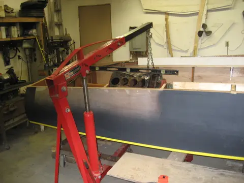
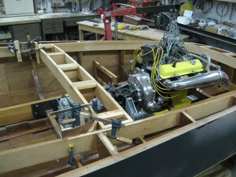
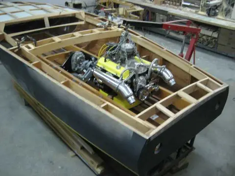
The stem, frames # 7, # 8 and a mockup 350 CID Chevy motor were installed.
A set of truck headers was inverted and bolted on as a prank.
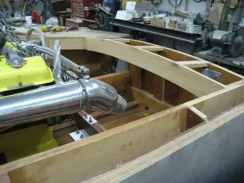
A Chris Craft exhaust system was trial-fitted. Lighter, more compact components will have to be located . . .
The rebuilt mo...
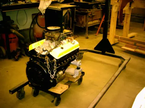
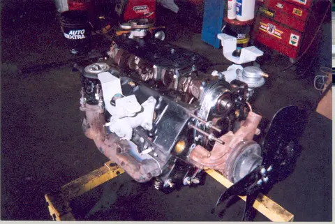
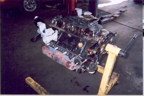
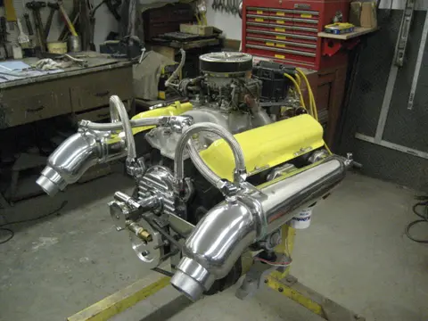
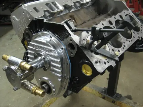
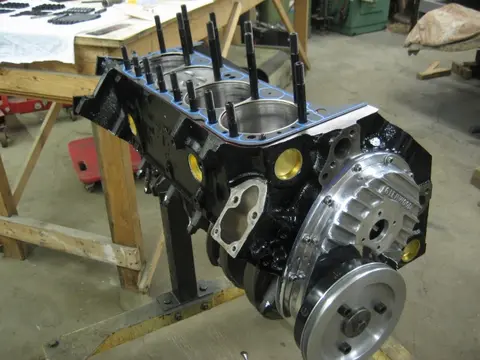
The first engine we built for the HOT ROD project was originally a 283 cubic inch Chevrolet marine unit salvaged from a 1968 Chris Craft cruiser. It has since been upgraded to a more potent 355 CID V8.
2. The Chris-Craft engine was oufitted with a Paragon 2:1 reduction transmission, a gear driven camshaft and a large capacity cast iron oil pan.
5. Certainly not the lightest engine package to power our boat, so we tore the engine down and replaced most of the parts with beefier and lighter performance parts.
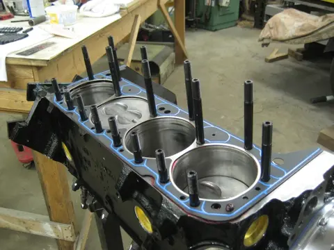
6. The engine was hot-tanked, magnafluxed to check for cracks and bored...
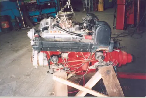
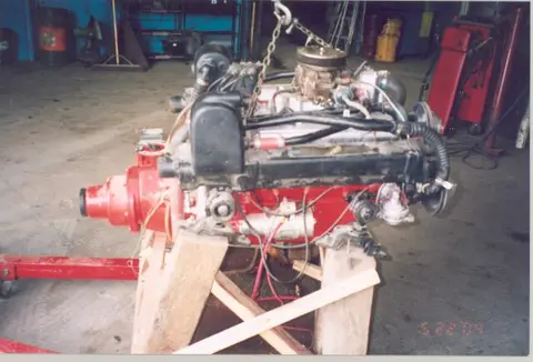
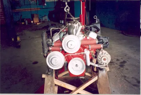
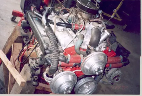
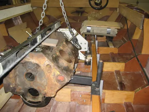
The engine was installed in the fullsize mockup. Motor mounts were fabricated, the wiring system was completed and an automotive cooling system was hooked up so we could fire up the engine. The intent is to break in the motor before it's installed in the finished boat. A cam driven water pump and marine exhaust will be swapped in at a later date.
Power upgrades include a mild marine hydraulic camshaft and lifter kit, a Crane Powermax H-266-2. Cam specs are as follows: - Advertised duration (Intake/Exhaust): 266/272 degrees - Duration at.050" lift (Intake/Exhaust): 210/266 degrees - Valve lift...
1. The propeller shaft hole will be drilled prior to sheeting the bottom. Two pieces of scrap plywood were screwed to the keel. Once the strut mounting holes were drilled, a stack of washers under each mounting hole was used to determine how much material had to be removed.
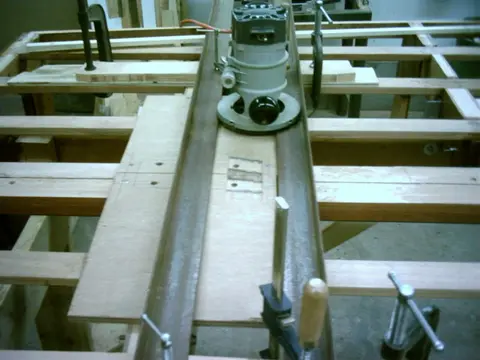
2. A jig was rigged up to flatten the strut mounting area. The router is run on two parallel lengths of angle iron.
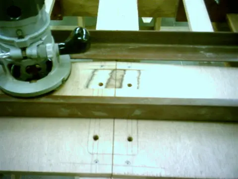
3. Depth of cut is adjusted to remove enough material so that the strut sits flat on the plywood.
4. A block plane can now be used to finish the job.
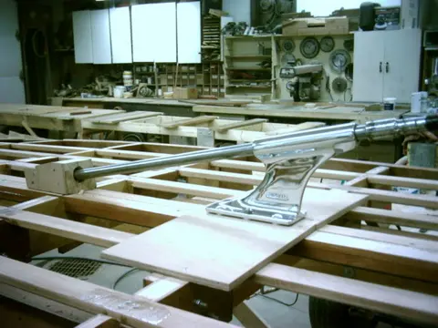
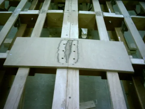
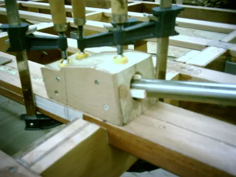
1. A 1/8" masonite spacer was fabricated and slipped under the strut to simulate the thickness of two layers of fiberglass cloth which will eventually cover the hull. The strut was bolted into position and an 8' long piece of 1" round bar was fed through the strut to simulate the propeller shaft.
2. A guide block was loosely clamped to the keel. Click here to see how the guide was made.
3–4. Push the shaft through the guide block until it contacts the keel and mark the point. Shim the shaft until it's centered in the gui...
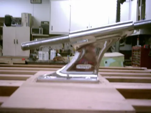
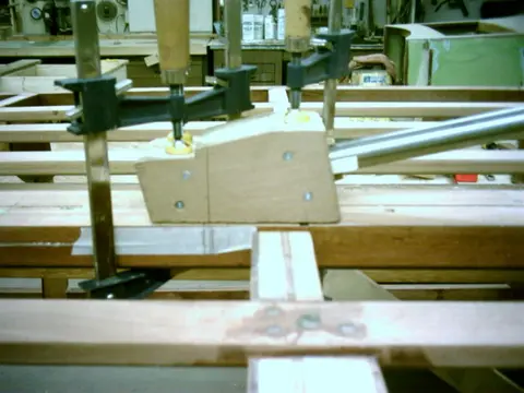
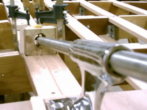
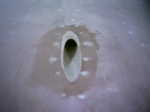
1. A fiberglass tube was inserted into the shaft hole. Click here to see how the tube was made.
2. This is a view from inside the boat. An 8' long shaft was fed through the strut and shaft hole. A 1" hole was drlled in frame #4 to position the shaft at 12 degrees.
3. A 1" ID x 1-5/8" OD rudder shaft collar inserted into each end of the tube will center the shaft in the tube until the epoxy cures.. When the boat is righted, the tube will be ground flush with the keel. Two laminations of fiberglass cloth will be applied to...
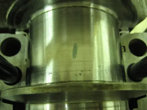
1. After the engine was run for several hours, we removed it from the mockup and dropped the oil pan to check the bearings. Even though we had the block hot tanked both before and after cylinder boring, there was clearly some scale in the pan.
2. The engine was disassembled and sent out to the machine shop for inspection. While we were at it, we added a Moroso windage tray and an ARP stud kit. Since switching from main cap bolts to studs affects the bearing clearances, the main caps were installed and align-bored to restore the clearances.
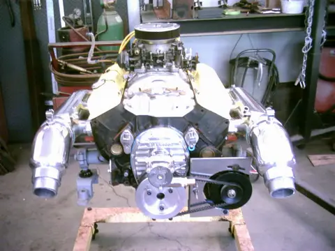
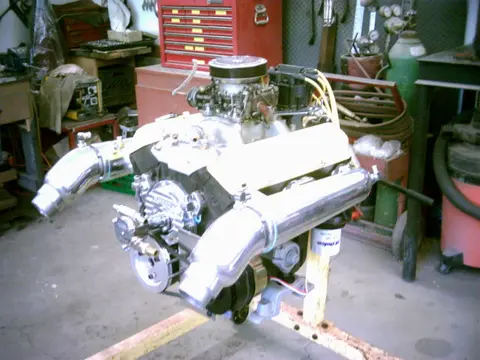
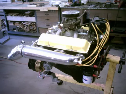
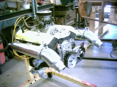
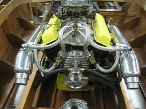
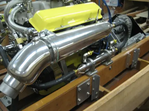
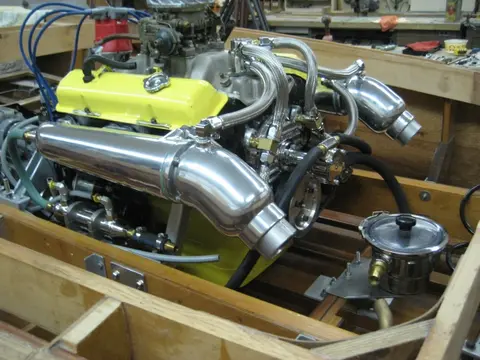
1–2. Glenwood header manifolds, 15 degree elbows, aluminum front cover, cam-driven water pump and a custom stainless steel alternator bracket complete the engine.
3–4. Click the 'Play' button (>) to see the video.
5. Closeup view of the alternator bracket. It extends back to the engine mount for added support.
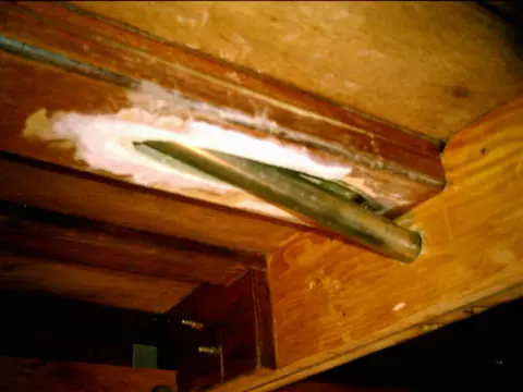
1. The shaft tube was epoxied and trimmed. Click here to review how the strut and tube were fitted when the keel was installed.
2. View from inside the hull. The plan is to fiberglass the keel before installing the shaft log.
3–4. Strut and shaft installed.
5. Viewed from the top.
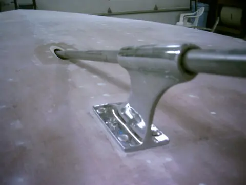
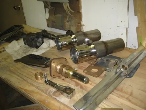
1. Photo quality should improve drastically from this point on. We bought a new Canon PowerShot SD600 digital camera. Hopefully the closeup and white color balance issues I had with the old camera are a thing of the past ! The rudder and rudder support bracket are back from the machine shop. 3-1/2" stainless steel pipe stubs were tig-welded to the Gibson Transom Mount mufflers. We also picked up a 1350 series Center H Yoke which will replace the torque tube.
2. These performance mufflers should be legal at idle. Can't wait to hear them when that 283 comes to life !
3. A bare-bloc...
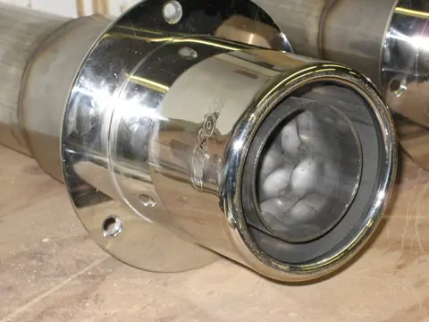
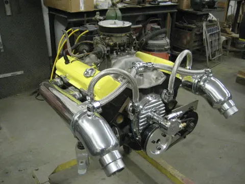
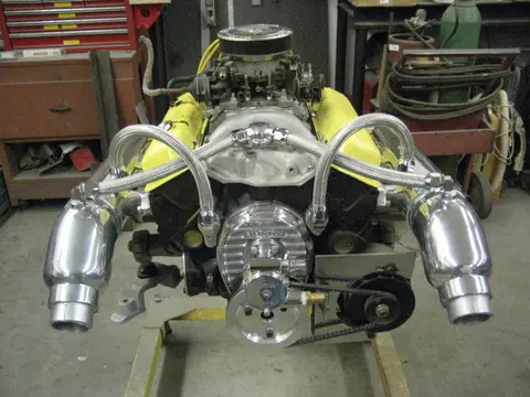
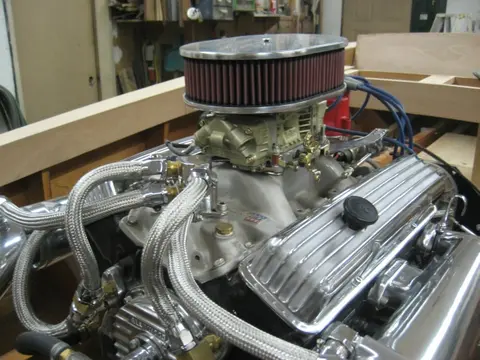
1. Time to do some plumbing ! Stainless steel hose liner and chrome hose ends were added to the top of the engine. What a difference a new digital camera makes !! Compare this photo with the previous five photos...
2–3. Click the 'Play' button (>) to see the video.
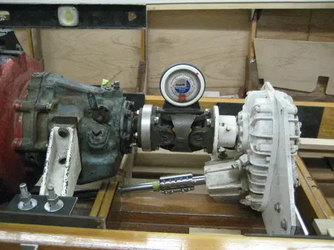
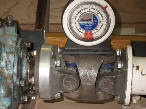
1. The H joint was bolted up to the transmission flange. The v-drive was pushed back and down until the propeller shaft coupler rotated freely on the propeller shaft.
2. An inclinometer (angle finder) was used to set the H joint at 0 degrees. The v-drive mounts can be now be welded in their final location.
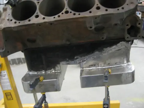
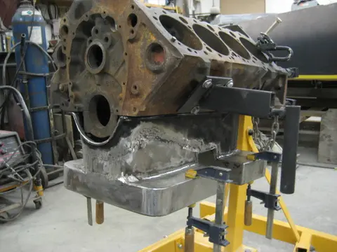
The oil pan sump was cut to move the engine 1-1/2" aft and 2-1/2" lower. This will obviously generate quite a bit of work . . . A simpler solution would have been to either install the frame timber on the aft side of the frame or move the entire frame 2" aft. If the latter is done, the frame outline would change (frame would not be as wide) so you'd have to loft frames #0 through #5 to pick up the new chine and sheer points.
1. The bottom of the rear sump was cut and replaced with a kicked-out pan bottom. This mod will increase oil capacity by 3 quarts.
2. The ledge around the bottom...
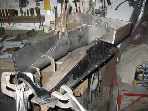
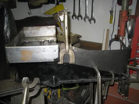
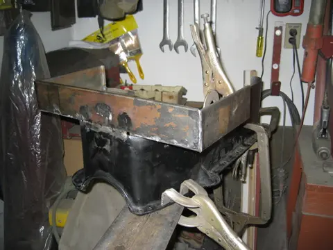
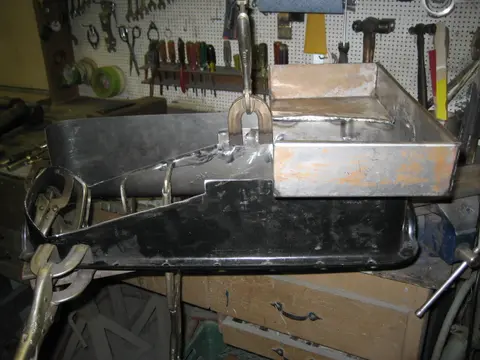
The oil pan sump was cut to move the engine 1-1/2" aft and 2-1/2" lower. This will obviously generate quite a bit of work... A simpler solution would have been to either install the frame timber on the aft side of the frame or move the entire frame 2" aft. If the latter is done, the frame outline would change (frame would not be as wide) so you'd have to loft frames #0 through #5 to pick up the new chine and sheer points.
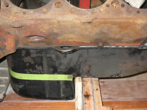
1. Side panels were joined with a flanged center section.
2. An air-powered panel flanger makes a neat joint between the pan and the newly grafted material.
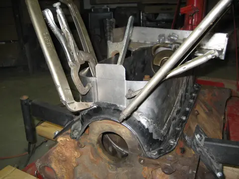
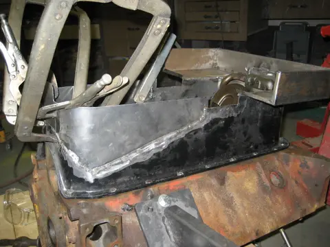
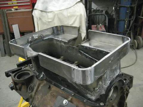
1. After much mig welding and grinding, the pan is starting to take shape...
2. Corners were cut back and rounded by adding hand-formed 1-1/2" radius sheet metal corner pieces. The joints were metal-finished to hide the welds.
3. View from inside the pan.
4. Front sump kickouts are 3/4" narrower than the rear.
5. Much grinding and cleanup is required on the inside of the pan.
6. Two 16 gauge bottom panels were cut and fitted.
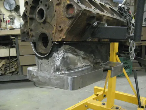
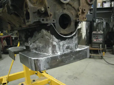
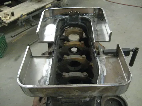
1. Two 16 gauge bottom panels were cut and fitted.
4. Trial fitting before final welding.
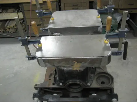
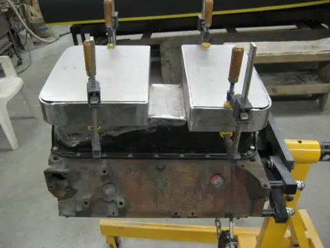
1. Trial fitting before final welding.
10–11. Now that looks a lot better !
12–13. Before we modified the oil pan, the rear sump straddled a frame. When viewed from the side, it stuck out quite a bit above the carlings. By altering the pan, the engine sits 2-1/2" lower which should lower the boat's center of gravity and improve handling.
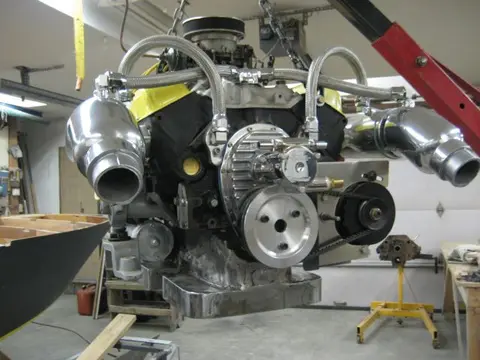
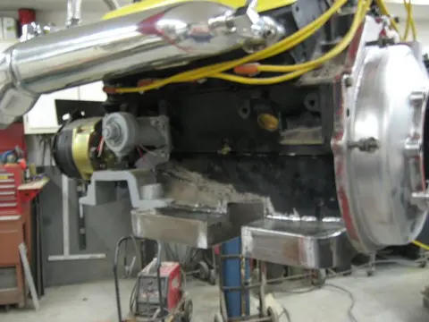
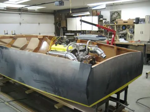
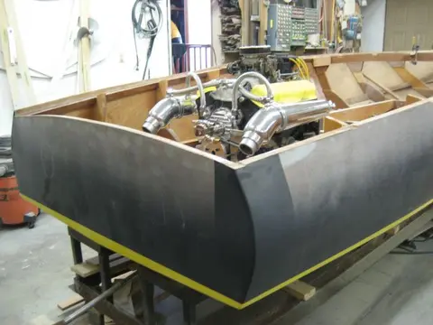
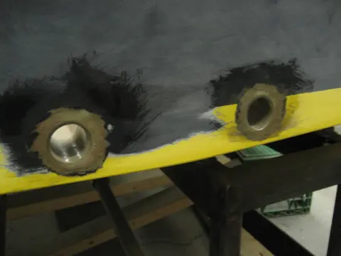
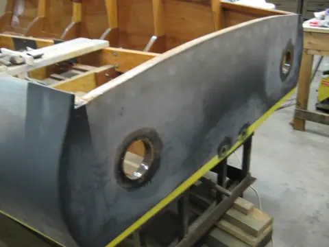
1. The transom drain plugs were cut out with a hole saw. Fiberglass tubes were fabricated and epoxied into the holes.
2. A hole saw makes quick work of cutting out the exhaust outlet holes.
3. Interior view of the transom. A 3/4" marine plywood backing plate was fabricated and epoxied to the transom.
4. The inside lip was waterproofed with one layer of 6-1/2 ounce fiberglass cloth. The hole was drilled 1/8" oversize to allow a thick bead of sealant around the exhaust tip's circumference.
5–6. The Gibson Transom Mount Power Tip mufflers look sweet ! Click here to see the...
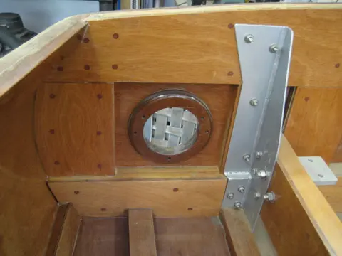
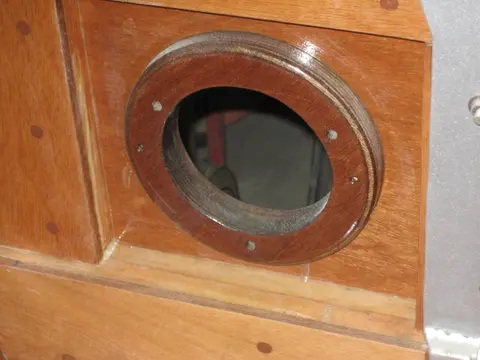
1. We fabricated a frame truss plate to span the stuffing box at frame # 4. It's made from 3/8" thick T356 aluminum plate. The v-drive and transmission mounting plates were bolted to the stringers with 3/8" stainless steel machine bolts. Also visible in the top left corner of the photo is the carling. We'll have more pics of this after it's been all glued up.
2. We'll be installing a stainless steel pop-up bow light in the strongback. This will require routing out a rather large hole which will seriously affect the member's integrity. We therefore laminated three pieces of 1/4" 5-ply...
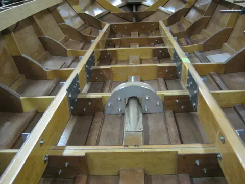
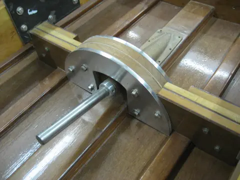
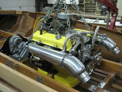
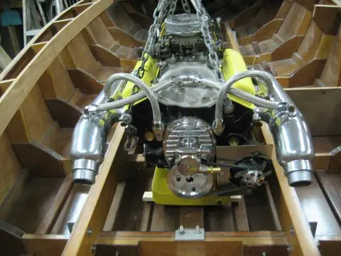
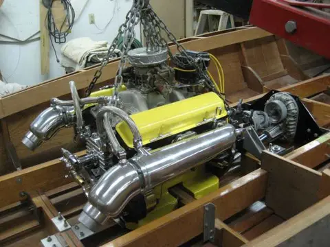
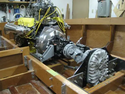
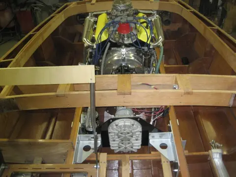
1. Here's the day I've been waiting for ! Engine, transmission and v-drive installed with very few issues.
2–3. We don't have enough clearance between the torque tube guard adapter and the v-drive take-off hub. The hex-head bolts used to retain the guard will have to be swapped out for flat head machine bolts.
6–7. Here's a close-up of the oilpan straddling frame # 2.
8. Oil capacity has been expanded from 4 quarts to 12 quarts.
9. The custom oil pan lowered the engine by 3-1/2". A lot of work, but the engine is horizontal and nicely nestled into the boat.
10. The...
1. The intermediate deck beam straddles the carlings at frame # 4.
2. Coaming corners were radiused with plywood veneer. We ran some 1/8" marine- grade mahogany plywood through the planer to remove one face. This makes it much easier to bend !
3. Transom deck beam is 9" wide.
4. The bottom edge of the beam was molded to a width of 3-1/2".
5. View from the transom.
6. Here's my friend Colin finish-welding up the v-drive mounting plate. We spent the day finalizing the transmission mounts. With all components bolted in, we measured for the propeller shaft.
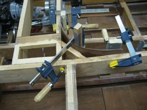
1. The Hardin Marine thermostat housing required us to re-plumb most of the engine plumbing.
2. A Glenwood oil cooler was mounted to the stringer. This should reduce engine oil temperature and increase engine life.
3–4. Yet another Glenwood oil cooler was installed below the Velvet Drive's fill plug level. This adds extra capacity to the system and ensures that the trans is at its maximum fill level at all times. An MSD billet aluminum marine distributor, digital ignition box complete the engine installation.
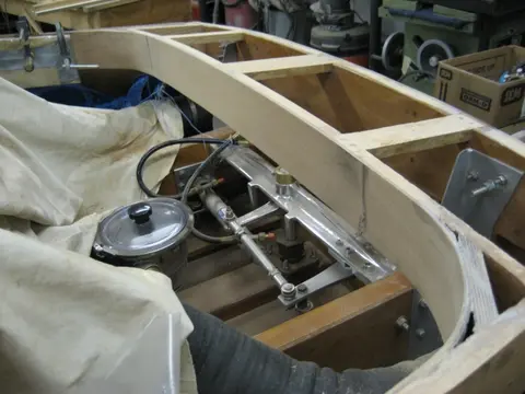
5–6. Last of the hydraulic steering components were installed. A G...
1. First step was to drain the engine oil and remove the transmission.
2. The Paragon HF7 1:1 ratio hydraulic transmission was slipping badly so it will also be rebuilt.
3. The transmission's splined input shaft mates to the crankshaft-mounted drive plate hub.
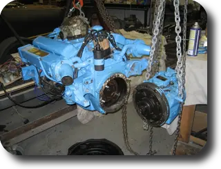
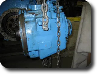
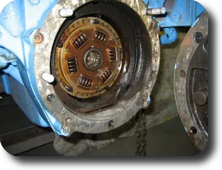
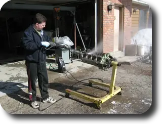
1. Pressure washing the engine block.
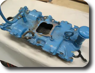
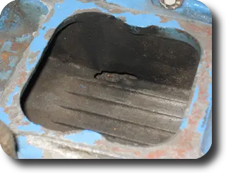
2–3. Intake manifold has a large hole in the bottom of the plenum. It will have to be replaced.
4–5. Engine Clearances
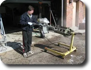
1. We've been working away at the boat over the winter but haven't much to show so far. Work on the cockpit continues. Over the next few weeks, we'll be laminating several layers of.100" veneer over the carlings. This will give a nice smooth radius to the inside corners. Click here to see how it was done.
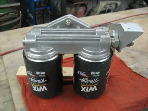
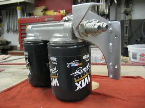
2–3. We fabricated a custom support bracket for the remote dual oil filters.
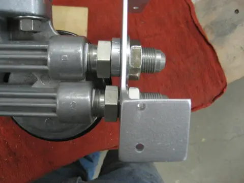
4. A bulkhead fitting connects the bracket to the oil filter head assembly.
5. The two holes on the right of the photo mount to the v-dri...
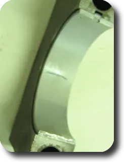
2. Cut and place a strip of plastigauge on a main bearing cap.
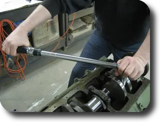
3. Torque the main bearing cap bolts to 65 ft/lbs.
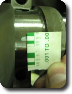
4. Determinine the clearance by matching up the compressed plastigauge strip with the plastigauge kit's ruler. Crankshaft main bearing clearance: 001" -.004"
5. Coat the camshaft running surfaces with assembly lube and install it in the engine.
6. Install rear oil seal.
7. Locate the camshaft gear's timing mark and mark it with some Liquid Paper.
8. Install the crankshaft and main bearing caps. Ensure that the crankshaft and camshaft timing marks a...
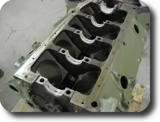
Assembly begins.
Water pump sprayed with Nason Urethane Clear to protect the raw aluminium and bronze parts.
Polyester body filler applied to the valve covers.
Primed, base-coated white Imron and topcoated with blue acrylic enamel.
Paragon HF7 transmission bead-blasted and chemically stripped.
Primed.
Base-coated.
Top coated.
Mounted on the engine run stand and re-assembled.
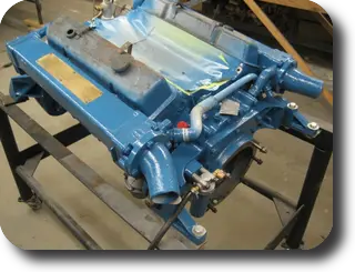
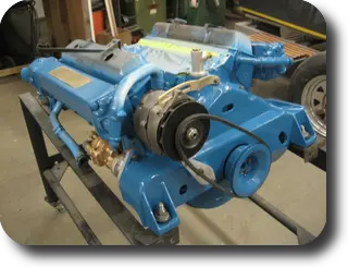
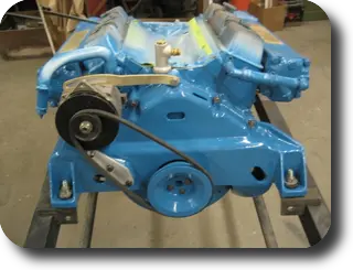
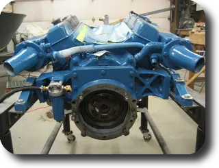
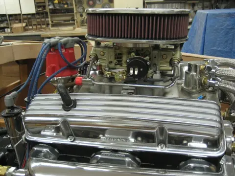
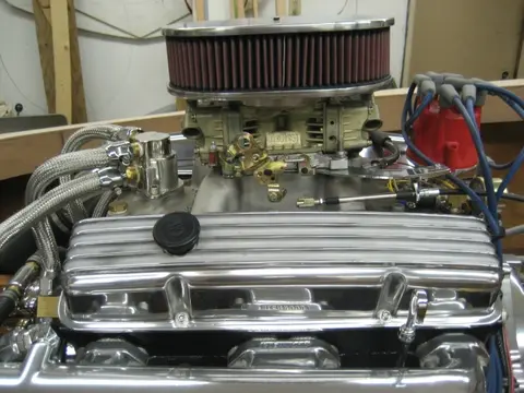
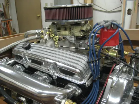
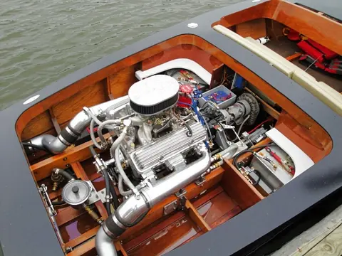
The original Carter 3660 carburetor was upgraded to a Holley 600 CFM marine four barrel carburetor. The Hardin Marine flame arrestor uses a K&N air filter capable of flowing 30% more air than a stock flame arrestor. Also visible in the background is a steering wheel connected to a Teleflex hydraulic SeaStar Pro Tilt helm. Click here to see more detailed engine photos.
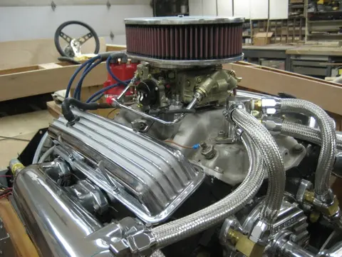
1. The original Carter 3660 carburetor was upgraded to a Holley 600 CFM marine four barrel carburetor. The Hardin Marine flame arrestor uses a K&N air filter capable of flowing 30% more air than a stock flame arrestor.
2–4. Click the 'Play' button (>) to see the video.
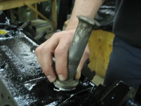
1. To check the main bearing oil clearance, we cut a plastigauge strip and placed it on the crankshaft journal.
2. The main bearing cap was lightly oiled (to prevent the plastigauge strip from sticking to it)...
3. ... and torqued to 65 ft/lbs...
4. ... The cap was removed...
5. Clearance is determined by matching up the compressed plastigauge strip with the plastigauge kit's ruler. Crankshaft main bearing clearance: 001" -.003".
6. Hydraulic roller retrofit The early style non-roller block was upgraded to a hydraulic roller setup by using a Comp Cams hydraulic rol...
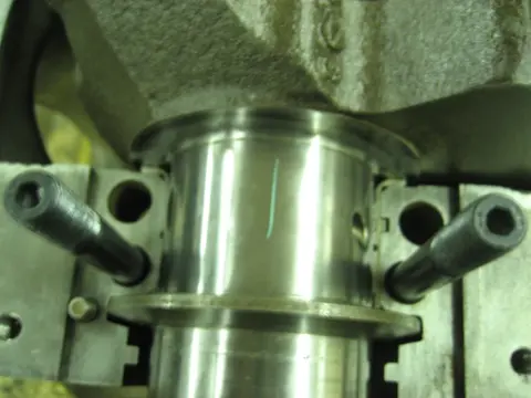
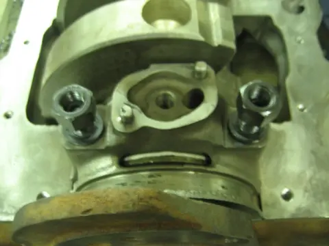
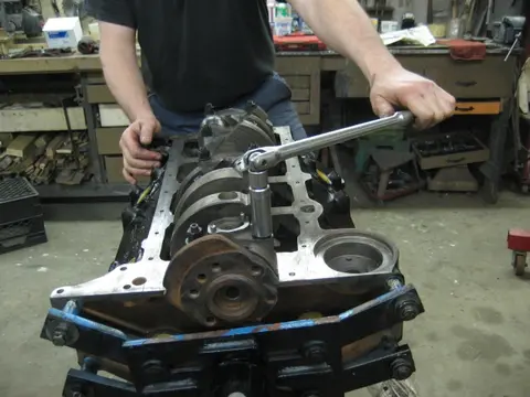
2. Pistons are TRW.030" over flat top forged units.
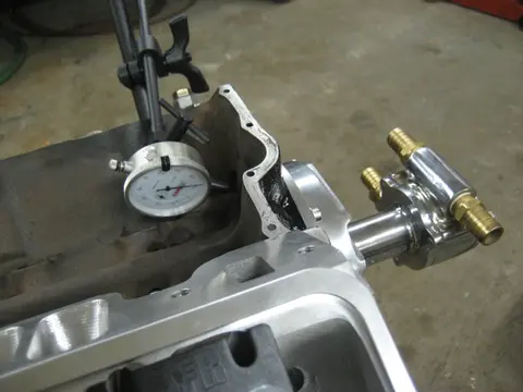
3. Checking camshaft end play with a dial gauge.
4. We had to fabricate an.048" shim to slip under the cam drive water pump drive plate in order to get the required.005" -.010" camshaft end play clearance.
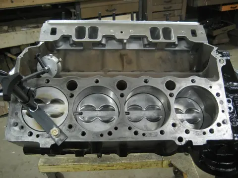
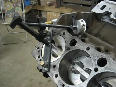
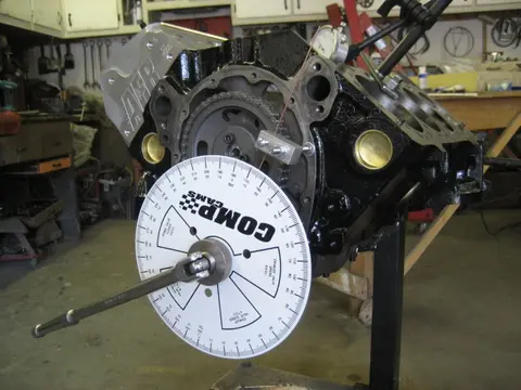
A Comp Cams degree wheel kit was used to ensure that the camshaft was installed according to specifications.
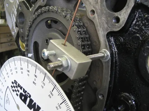
We fabricated a Top Dead Center pointer from a piece of 1/4" threaded rod, an aluminum block and a steel welding rod.
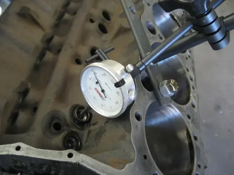
A solid lifter was inserted into the lifter bore to determine maximum valve lift and cam timing.
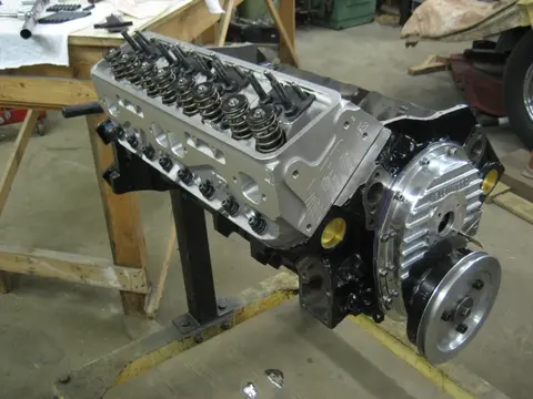
1. The stock head bolts were upgraded with an ARP head stud kit.
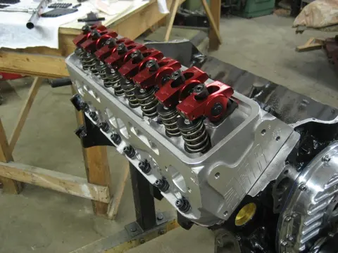
4. Comp Cams Magnum aluminum roller rockers, roller lifters and pushrods complete the valvetrain.
6. If you click the image to enlarge it, you'll see the drive cog for the cam drive water pump. The plate is bolted to the end of the camshaft. The timing chain cover is another Glenwood item.
7. A Holley 600 CFM Marine performance calibrated four barrel carburetor is mounted to an Edelbrock RPM Air-Gap intake manifold.
8. The Hardin Marine flame arrestor uses a K&N air filter capable of flowing 30% more air t...
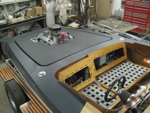
We've decided to build a removable hard shell tonneau cover to protect the engine and related parts from the elements while towing. Normally this could be done with boat canvass stretched over the rear cockpit and fastened around the cockpit coaming with snaps, but we were after a cleaner look without any visible fasteners.
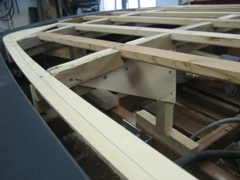
1. We built a removable buck supported on the engine stringers. Cambered deck deams were produced and spaced on every frame. 1" x 2" battens were rabbeted into the deck beams. The structure will be covered with 1/4" plywood and covered with 10 ounce fiberglass cloth....
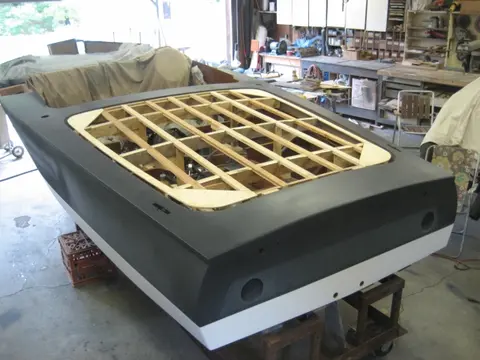
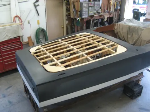
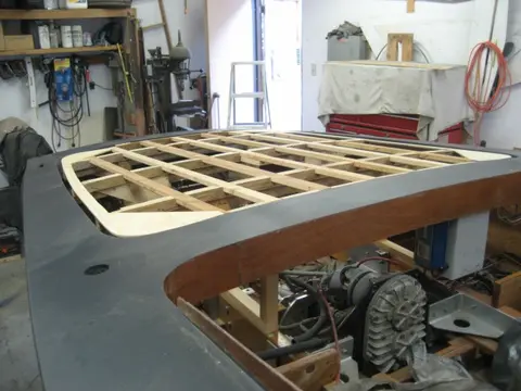
We've decided to build a removable hard shell tonneau cover to protect the engine and related parts from the elements while towing. Normally this could be done with boat canvass stretched over the rear cockpit and fastened around the cockpit coaming with snaps, but we were after a cleaner look without any visible fasteners.
Click here to see how the cover was fabricated.
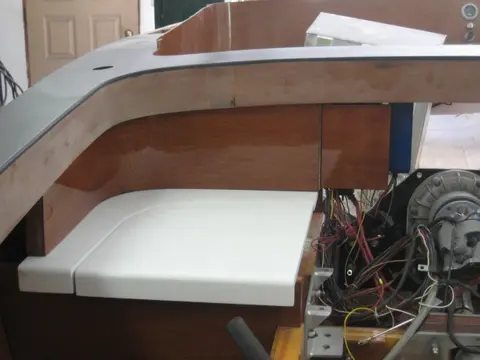
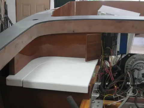
Port side fuel tank was placed on its cradle and the jumpseat panels were installed. The cockpit coaming is ready for another round of clearcoat.
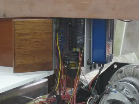
1. The distributor's MSD ignition box (blue box) mounts to the side of the electrical box with rubber vibration dampers.
2. A stainless steel piano hinge was used to hinge the electrical box door.
3. The electrical box is very cramped but we managed to pack a Blue Sea Systems marine rated fuse block, a solenoid-actuated master disconnect switch for the battery and an electrical fuel pump relay. We'll sort out the mess of wires when the...
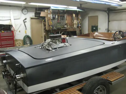
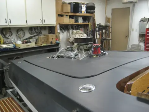
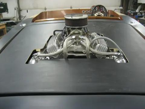
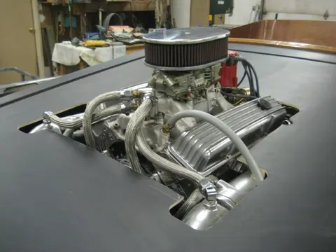
1. Here are a few photos after trimming the tonneau cover to fit around the engine. Still lots of trimming to do, but it certainly has the look I had envisioned ! It's going to be sweet !
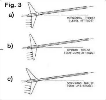
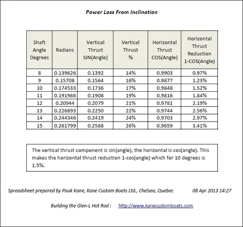
Steeper shaft angles increase upward thrust which increases transom lift and decrease bow lift. Lower shaft angles reduce upward thrust and increase bow lift. More thrust is available to propel the boat. Reference : Basic Propeller Theory - Prop Shaft Angles (sfmbc.net)
How to measure propeller rake The Rake measurement indicates the angle of blades tilt towards or away from the transom. The rake angle is measured on a line extending from the center of the hub through the center of one blade. A propeller with 0 degree rake has blades 90 degrees perpendicular to the center of the hub. A 20 de...
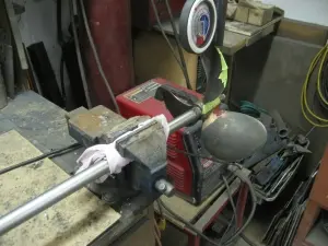
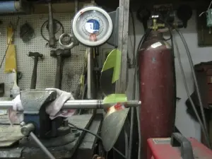
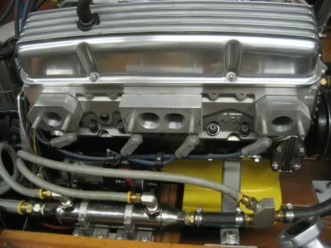
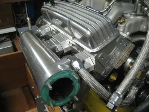
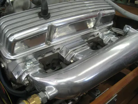
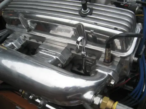
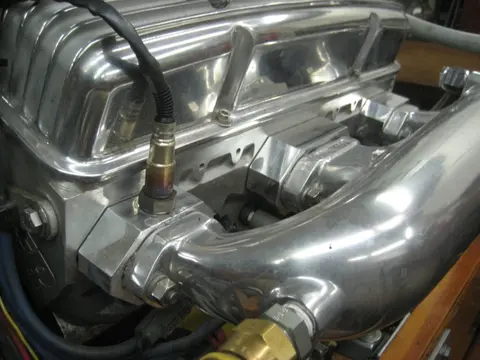
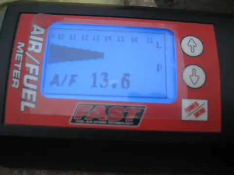
To help tune our carbureted engine, we fabricated aluminum spacer blocks to mount a wideband oxygen sensor in each cylinder bank as close to the exhaust ports as possible. The sensors will feed an air-fuel meter which will indicate if the air-fuel mixture is rich or lean. The spacer blocks are prototypes for an automotive TBI to marine conversion kit that we've been working on. We'll have more on that project as soon as its up and running !
1. We fabricated a set of exhaust manifold spacers from 1-1/2" thick aluminum stock.
2. The original allen head cap bolts were replaced with stud...
1. The sensors are only installed when we wish to check the carburetor's calibration after we've made jetting changes. A stainless steel oil pan drain plug is installed when the sensors are not needed.
2. Sensor fitted to the first cylinder bank...
3. ... and the second cylinder bank.
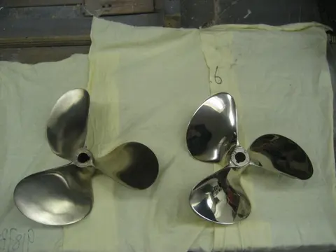
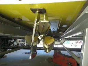
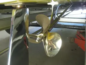
1. The prop on the left is our old OJ 12x16p LH 3 blade Nibral propeller. It has performed flawlessly, but we wanted to increase our cruise RPM by several hundred RPM, so we had a new OJ propeller reworked to an 11x14p.
2. (Index)
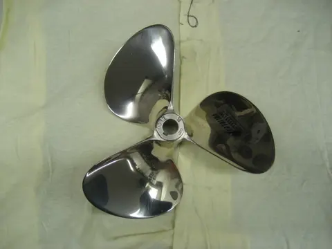
The propeller shaft was shortened by 5/8" to reduce the distance between the aft end of the strut and front face of propeller hub.
Diameter was reduced from 12" to 11" which yields 1/2" more blade tip clearance.
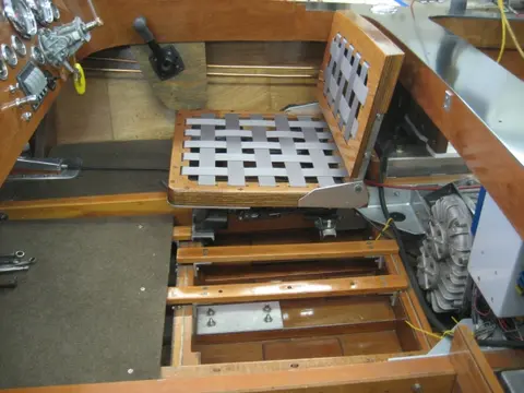
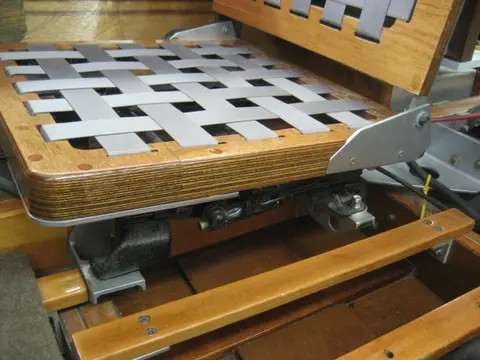
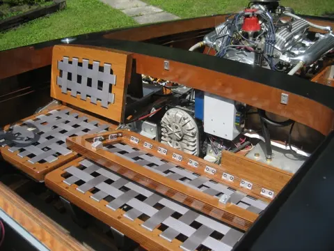
1. The rubber webbing we originally used for the seat base and back was too soft, so we replaced it with seat belt webbing. Here are a few photos of the final installation.
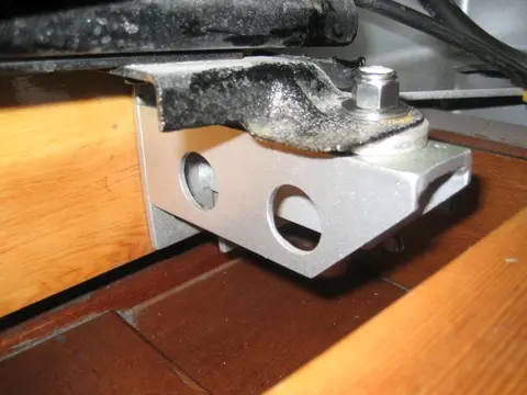
2. Custom fabricated steel brackets mount the adjustable driver's seat base to the engine stringer.
3. Here's a close-up shot of one of the brackets.
The seat tops are just proud of the deck surface.
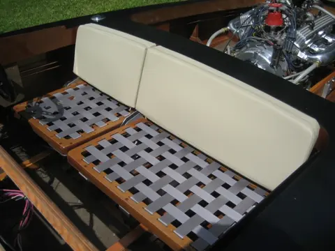
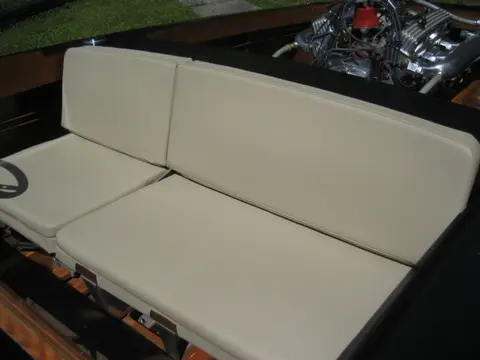
1. Here are some photos of the completed upholstery.
2. The passenger seat back folds down for access to the v-drive. There's enough space behind the seats to store the paddle, rope boarding ladder and other boating stuff.
3. Driver's seat back cushion is slipped onto the seat frame and attached with a velcro strip along the seat back's bottom edge. The passenger seat back is held in place with snap buttons.
4. Seat pan cushions fit like a glove...
5. We'll have to raise the passenger seat's hinge pivot point so that th...
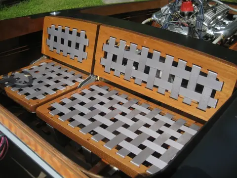
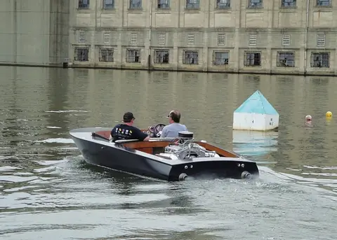
At the Glen-L Boatbuilder Gathering, Lake Nickajack, Tennessee. Photo courtesy of Gayle Brantuk, Glen-L Marine Designs Click on the links below to see the latest updates. Seats Deck Exhaust System
Gathering of Glen-L Boatbuilders at Lake Nickajack Tennessee, September 16-18, 2011. We attended the fifth annual get together of Glen-L boat builders, family and friends organized by Glen-L builders. Photo courtesy of Gayle Brantuk, Glen-L Marine Designs Click on the link below for more details : Gathering 2011 Trip Report and Photos
The air-fuel meter can monitor each cylinder bank individually or can provide an average for both cylinders. Averaging both sensors at 2000 RPM gave us this reading. Our jetting is in the ballpark, so we'll log our next run under load and cruise conditions and try our next setup. The meter will store up to 25 minutes of data in the dual sensor mode. This tool really takes the guesswork out of tuning a carburetor !
1. We fabricated an alignment jig made from 3/4" plywood scraps and hose clamps to mark location of turnbuckle mounting holes on the 7/8" OD control shaft.
2–3, 5. Here's an excerpt from the Glenwood Marine Catalog explaining how the cavitation plate override system works: "On high speed boats, quick accurate setting of the cavitation plate is desirable for safety and best performance. Using a combination Foot Control and Control Handle with an Override Assembly makes such adjustment quick and positive. Usually the cavitation plates are set by the hand control to the desired pitch. Ho...
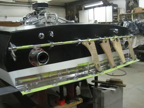
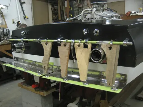
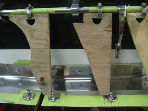
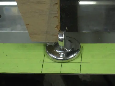
Hole centerlines were marked with a die grinder cutoff wheel. Parts were reassembled and measurements were double checked before sending the control shaft out for spot facing and drilling.
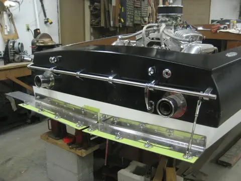
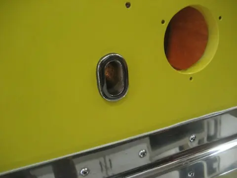
1. Opening for the thru hull fitting is to the left of exhaust pipe hole. This should place the thru hull roughly 1" above the waterline.
2. We used a hole saw and a sabre saw equipped with a metal cutting blade to cut through the stainless steel transom support.
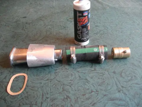
3. Here are the cast aluminum oval thru hull and related components. We cut a custom gasket for the thru hull flange which will be bedded in Permatex "The Right Stuff" gasket sealant.
4. Here's the finished product.
5. Here's the view from inside the boat.
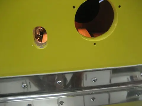
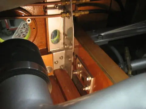
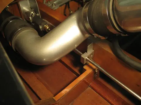
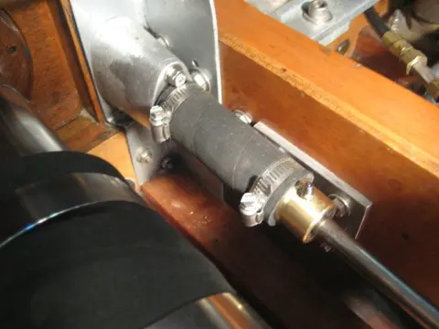
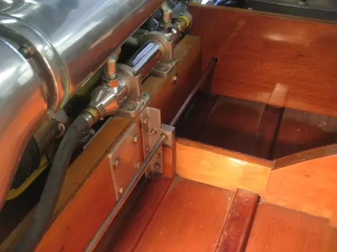
1. It's a very tight fit, but there's just enough room for the thru hull fitting and cavitation plate pedal control rod.
2. The thru hull retainer thickness had to be reduced 3/4" to compensate for the 3-1/2" thick transom.
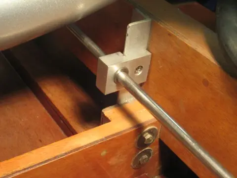
3. We built custom pillow blocks from 1" x 2" aluminum bar stock.
4–5. The bar stock was notched to fit over the steel angle iron frame clips. We bored a 3/4" diameter hole through the bar stock and loctited a 1/2" ID x 3/4" OD bronze bushing.
6. To gain enough clearance for the foot pedal rod, the starboard side fuel tank cradle was modified to shif...