Hot Rod · step
Hardware & Fit-Out
Cleats, rudder and centerboard, tiller, oarlocks, deck gear.
Hardware & Fit-Out on every boat, not just the Hot Rod →
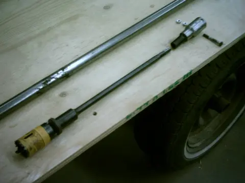
This section describes how to build a boring bar which can be used to bore the propeller shaft hole.
1. The 1" boring bar consists of a 1" round bar, a slip-on connector and a standard holesaw fitted with a 1/2" x 18" extension bar.
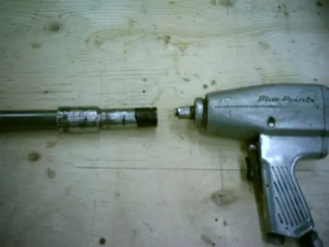
2. The drive end of the tool is fitted with a 1/2" drive impact socket.
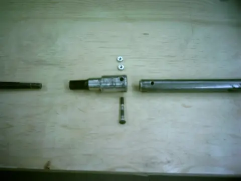
3. A 1" ID pipe sleeve is used to connect the 1" bar and the impact socket.
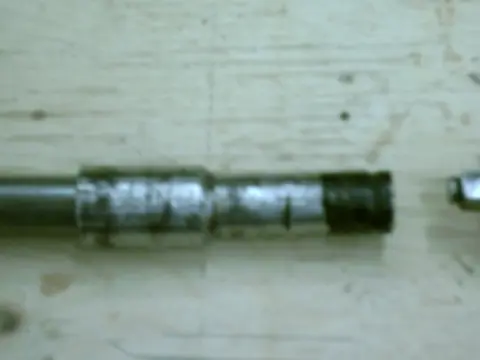
4. The coupler consists of a 1/2" drive 7/16" impact socket welded to a 1" ID pipe sleeve.
5. The pipe sleeve is drilled for a 1/4" x 2" through bolt.
6. To get the shaft hole started, a gu...
Since this boat will easily exceed 50 MPH, a Teleflex NFB Dual Cable steering system will be required. A used unit was scavenged from a junked SeaRay cuddy cabin cruiser. Two 15' cables and clevises will be needed to connect the cables to the rudder's tiller arm.
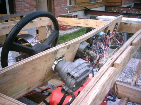
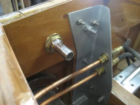
1. We've upgraded from a Teleflex NFB Dual Cable system to Seastar hydraulic steering. Running two hefty cables through the stringers to the tiller would have compromised the stringer's integrity, so we'll be running 3/8" copper lines instead.
2–3. Visible in this photo are the two fiberglass drain plug tubes. A brass sleeve will be slipped into the tube and sealed with 3M 5200 sealant. If any water leaks past the tube, the fiberglass tube liner will protect the frame from water damage.
4. In order to mount the cylinder within the stringers, we fabricated a second tiller which wi...
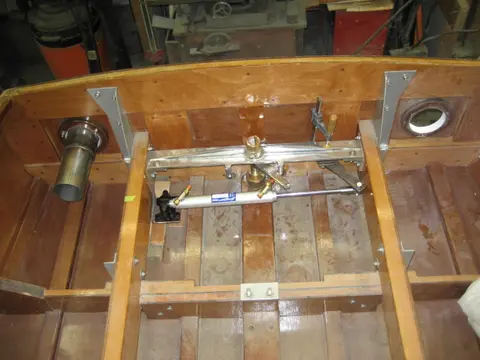
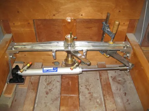
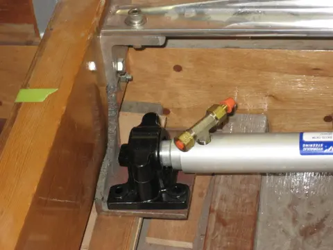
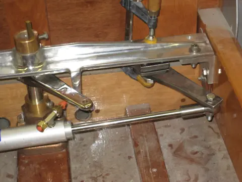
1. Steve at Ayling's Boat Yard has been busy in the machine shop refining the steering components. The slave tiller arm bushing housing was welded, the pivot pin was upgraded to 3/4" diameter stock and re-bushed to tighter tolerances. Nice work, Steve ! Click here to see more detailed photos. ( a new window will be opened)
2. Work on the boat will continue over the holidays, but we'll also make some time to enjoy the snowmobile trails. Can't be working in the shop all the time ! I'd like to wish all our visitors a Merry Chris...
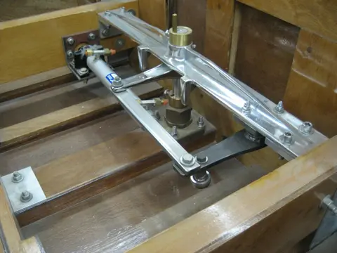
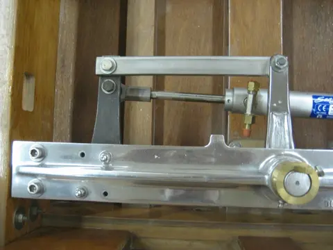
To complete the assembly, we fabricated a hydraulic cylinder mounting bracket and stainless steel tie bar. At a later date, we'll be replacing the tie bar with two tie-rod ends and a length of threaded rod.
A Gil offshore sea strainer filters raw water before feeding it into the cam-driven water pump and oil coolers.
1. More parts came back from the machine shop. The slave tiller arm bushing housing was welded, the pivot pin was upgraded to 3/4" diameter and re-bushed to tighter tolerances. Nice work, Steve !
2. Visible in this photo are the two 3/8" annealed copper tubing hydraulic...
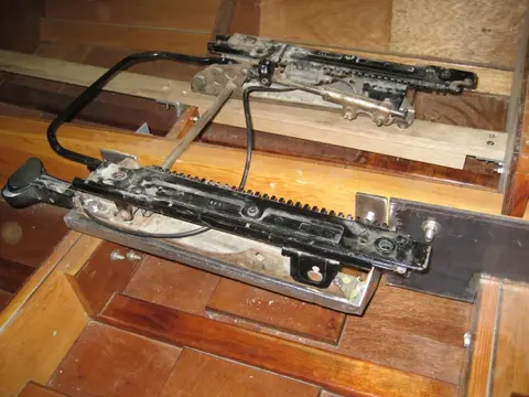
Seat tracks from a GM van are mounted to a set of custom fabricated brackets. One side bolts trough a sole support and the other bolts to the side of the motor stringer.
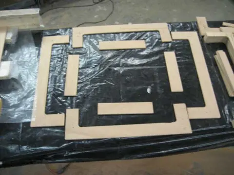
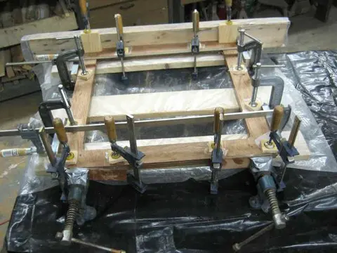
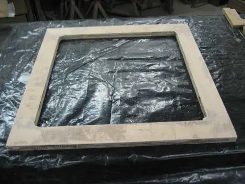
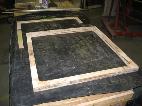
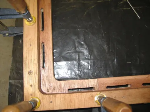
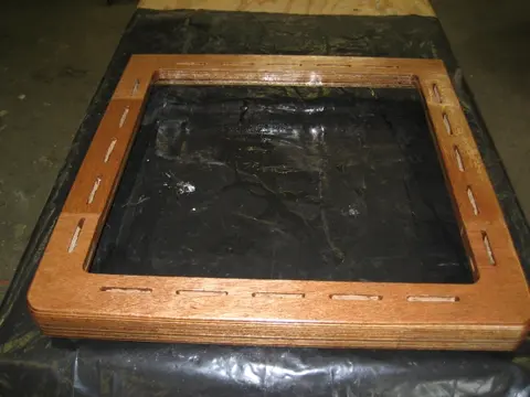
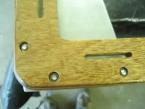
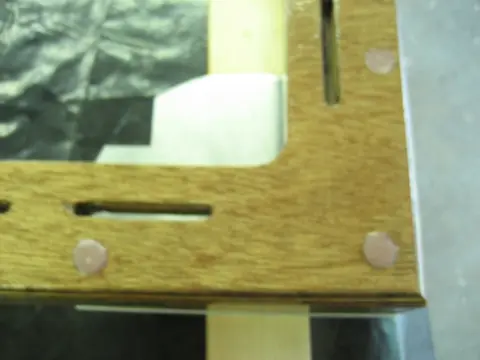
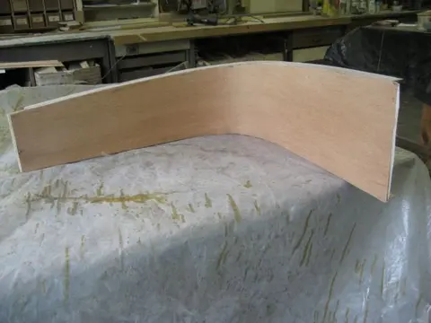
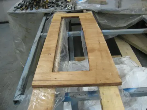
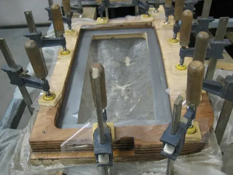
1. Normally we'd build the seat frames with 3/4" marine grade plywood. We had several leftover pieces of 1/4" plywood, so we chose to create a template, cut multiple pieces and laminate 3 layers to the required thickness.
2. Rotating the 'C' shaped corner pieces 90 degrees for each layer produces a very rigid rectangular frame free of fasteners.
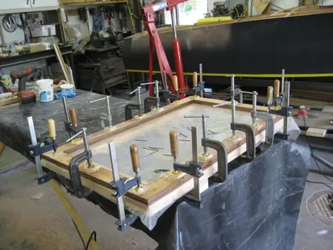
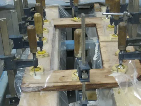
3. The 3 layers were epoxied and clamped.
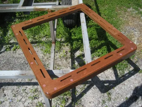
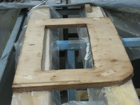
4. Here's the top layer after curing.
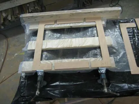
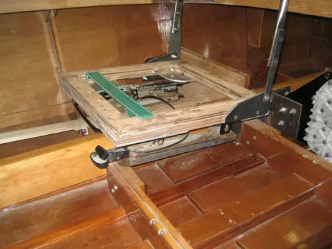
One of many trial fits.
1. The second layer was built up from 4 laminations of 1/4" marine grade plywood. A template similar to the one employed in the first layer was produced.
2. The second layer was epoxied to the first layer.
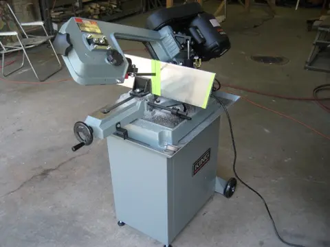
3–4. We splurged on a 5"x6" industrial duty dual-swivel metal bandsaw. It walks through 1/4" steel or aluminum plate with ease. What a difference a tool makes !
5. These aluminum corner plates will bolt to the seat rails.
6. We fabricated a steel backing plate to which we've bolted the seat back tilt mechanism.
7. Here's a close-up view o...
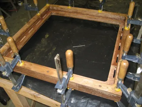
Front corners were radiused and the top edges were rounded-over before applying the first coat of epoxy.
The driver's seat is nearing completion. The rails provide 6" of horizontal travel, 3" of vertical travel at the front of the seat and reclining backrest. We've also started the passenger seat base. Click here to see how the seat was made. ( a new window will be opened)
1. 1/4" diameter holes were drilled through the 7 layers of plywood to retain the aluminum seat mounting plates. 1/4"-20 stainless steel nuts were set into 1/2" counter-bore holes.
2. To prevent the bolts from bonding to the epoxy, the nuts were drawn down with lightly-greased bolts and capped with an epoxy mixture consisting of West resin and 403 / 407 fillers.
3. A passenger seat base was laminated over a buck built from scrap 1"x6" stock. Dimensions are 22" wide by 36" long.
Two coats of Nason Clear applied with an HVLP spray gun finish up the driver's seat.
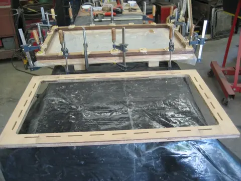
1. At the bottom of the photo, we see the passenger side seat base after routing for webbing. At the top of the photo, we're laminating the bottom half of the seat base.
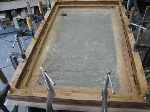
2. The two pieces are epoxied and clamped.
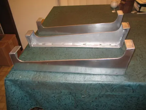
We could have built the passenger seat base supports from plywood, but aluminun will last forever. Our new horizontal metal bandsaw made quick work of cutting the 3/16" aluminum plate. Hope to install the seat base over the weekend.
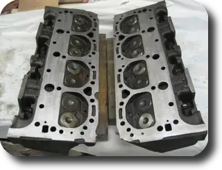
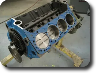
1. Rebuilt heads. New valves, valve guides and valve seats.
2. Marine head gasket.
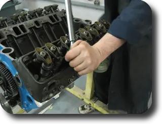
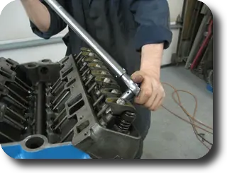
3. Cylinder heads torqued to 65 ft/lbs.
4. We completed the valve train by replacing the old solid lifters with a Comp Cams solid lifter kit. The original pushrods and rocker arms were in good shape so they were cleaned and reused.
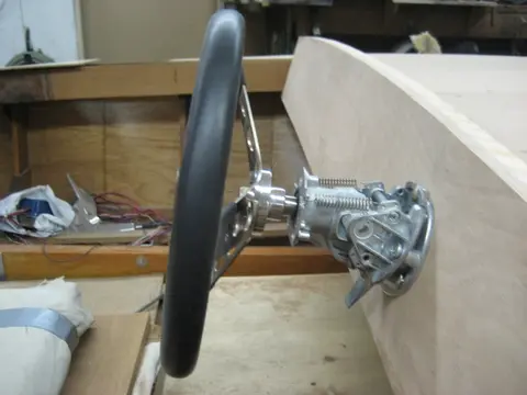
1–2. The tilt helm is a very nice feature.
6. We quickened the steering action to 3 turns lock-to-lock by using a SeaStar 2.0 Sport Tilt Pro Helm displacing 2 cu.in./rev. and a SeaStar BA125-7ATM cylinder. The tilt option was well worth the added expense !
7. An aluminum backup plate was fabricated to mount the hydraulic helm to the dash.
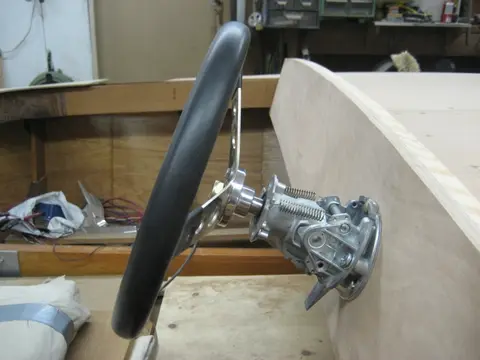
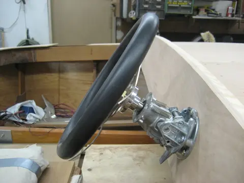
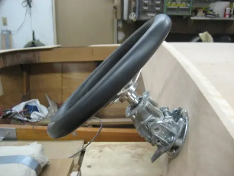
Work on the front cockpit carlings and dash continues. We've snapped a lot of pictures to describe the process. Click here to see how it was done.
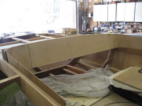
1–2. We encapsulated the inside dash surface with one layer of two ounce mat followed up with one layer of 6 ounce fiberglass cloth. This will prevent the exposed plywood surface from checking with exposure to the elements.
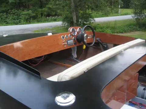
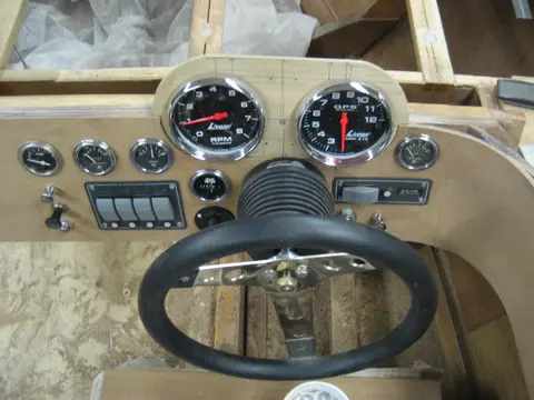
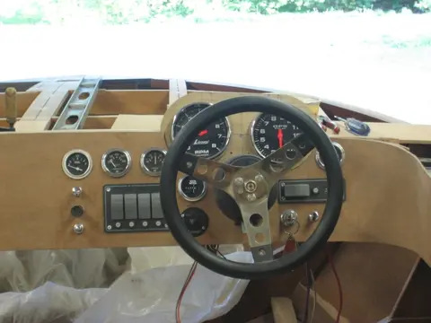
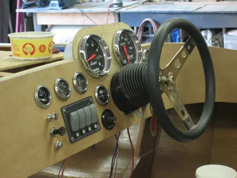
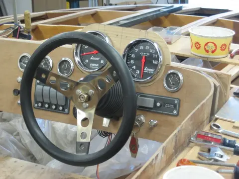
1. Gauges were installed over the weekend and are ready for wiring. The helm is a SeaStar Pro Tilt hydraulic unit. 5" Monster GPS speedometer and tachometer are made by Livorsi. The water temperature, oil pressure and volt meter gauges are vintage VDO units salvaged from a Chris-Craft cabin cruiser. The fuel level and hour meter gauges are Teleflex Heavy Duty gauges. Rocker switches are fully waterproof. GPS speedometer recall/reset toggle switch is located to the left of the helm. There's still another layer of mahogany veneer to apply on the dash before applying the final finish clear co...
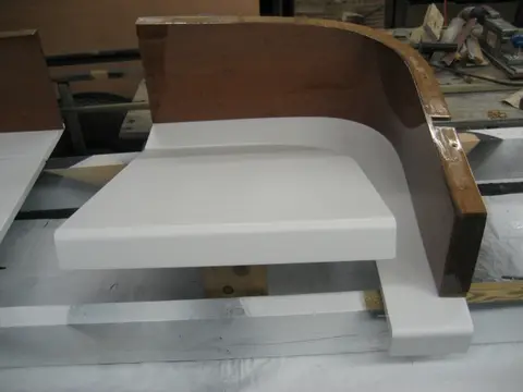
Casting was a success ! The piece fits like a glove and conforms nicely to the carling's lower edge.
1. Here's the part after we've pulled it from the plug. Total weight is less than one pound.
2. Edges were trimmed and the part was given a light sanding before coating with West Epoxy catalyzed with 207 Special Coating hardener. Aluminum clips will be used to retain the top flange to the carling. The lower flange will bolt to the seat bottom.
3. Ends were left long so that they can be trimmed after installation.
4. The starboard seat base was installed.
5. Front partit...
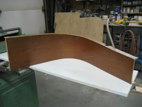
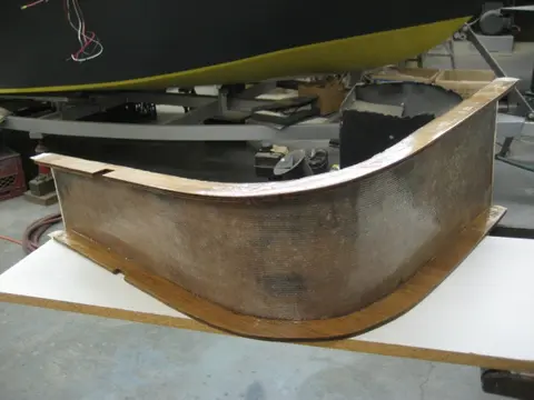
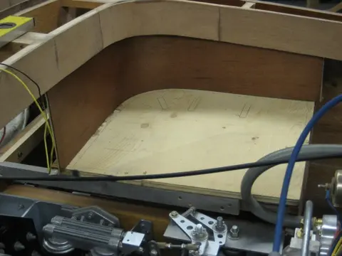
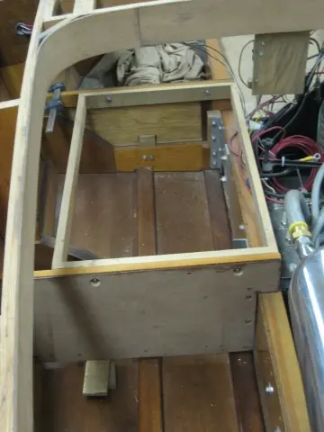
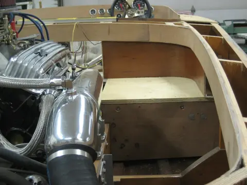
We extended the radiused corner coamings to the the rear jump seat backs. Since this photo was taken, the seat supports have been veneered and topcoated with several coats of epoxy and automotive clearcoat We're holding off on final assembly until the fuel tank cradles and battery box are installed.
Fuel tank cradles are ready to install. Click here to see the fuel tank cradle and jump seat construction photos.
1. Port side seat support completed.
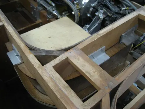
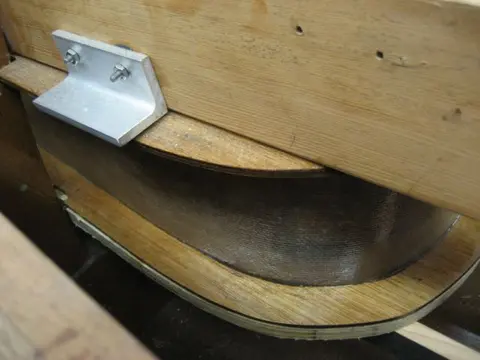
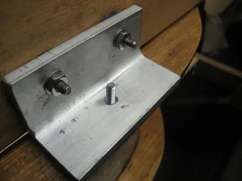
2. Aluminum angle clips were bolted through the rear cockpit carling to carry the seat support. Bolts were countersunk and epoxied to prevent the heads from turning. Wood plug bungs conceal the bolt heads.
3. The aluminum clip mates to the seat support flange. We've inset the seat support 3/4" from the carling's inside edge. This will allow room for padding and upholstery.
4. We didn't want the upholstered panels to have any exposed fasteners, so we drilled the clips for aluminum Sert-A-Nuts. These are similar to blind rivets, but they're...
1. The fuel tank cradles were built from 1/4" marine grade plywood sandwiched between a layer of 2 ounce chopped strand mat and 10 ounce woven roving laminated to both sides of the plywood. Building the cradles from aluminum stock would have been way quicker but the added weight would have required more flotation. Parts are lighter than aluminum and they float !
2. Loaded fuel tanks will be quite heavy, so we laminated two 1-1/2" ledger strips to the side of each cradle.
3. Fuel tank weight will be distributed to the top of the frames.
4. Parts were barrier coated with sever...
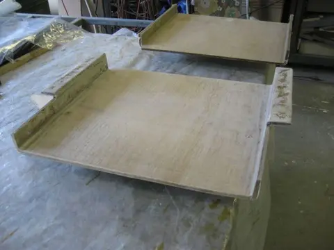
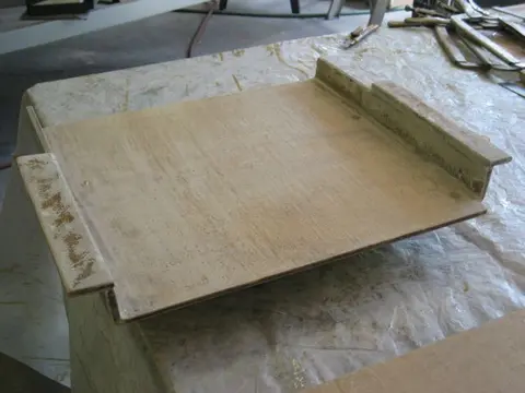
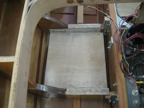
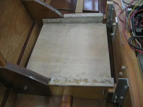
1. Passenger seat back hardware layer.
2. Passenger seat back webbing layer.
3–4. Both pieces are glued and clamped.
5–6. Passenger seat back folds to horizontal position.
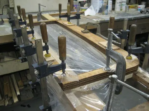
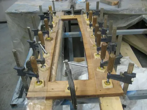
1–2. Driver's seat back webbing layer.
3–4, 6–7, 10–15. Passenger seat back folds to horizontal position.
5. Parts were trimmed and fitted.
8. Driver's backrest is fully adjustable.
9. Seat back tilt mechanism was taken from a GM van.
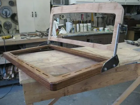
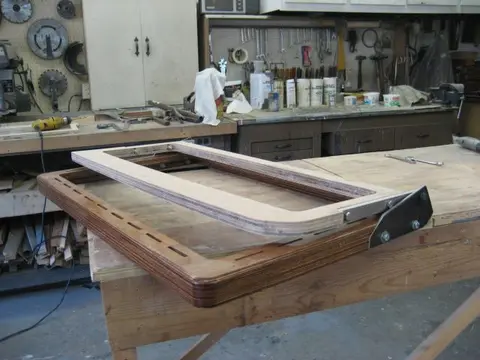
Here's the finished passenger seat ready for final installation. (Click the image for a higher resolution photo).
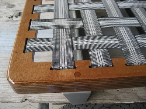
1–2. The rubber webbing was a very labour intensive job, but will make for very confortable seats !
3. The webbing was looped around a strip of 1/2" wide by 1/8" thick flat aluminum stock.
4. Two #6 x 3/4" stainless steel pan head machine screws were used to retain the webbing to the seat frame.
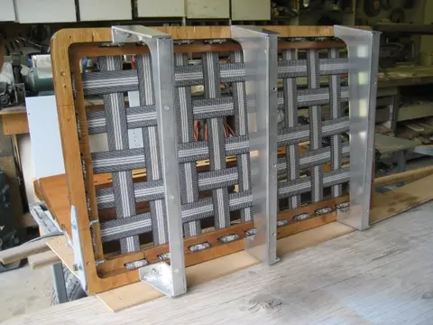
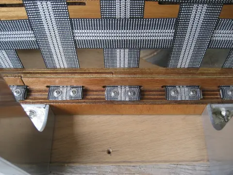
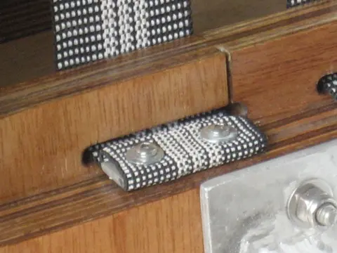
1. Final assembly for the Port fuel tank cradle and forward jumpseat bulkhead. Cradle bolt holes were bushed with fiberglass bushings. Sert-A-Nuts were installed flush on the inside face of the cradle flange.
2. Here's a view of the forward jumpseat bulkhead looking aft.
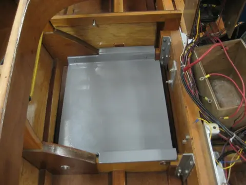
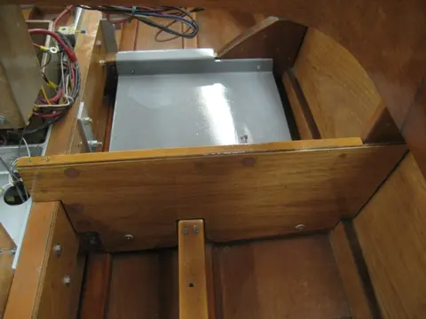
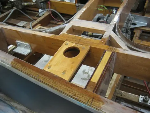
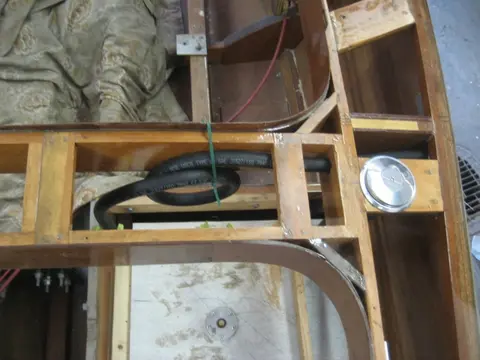
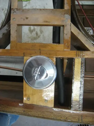
1. Fuel fill blocking was laminated from marine grade plywood and Douglas Fir stock. The plywood layer prevents the Fir from splitting.
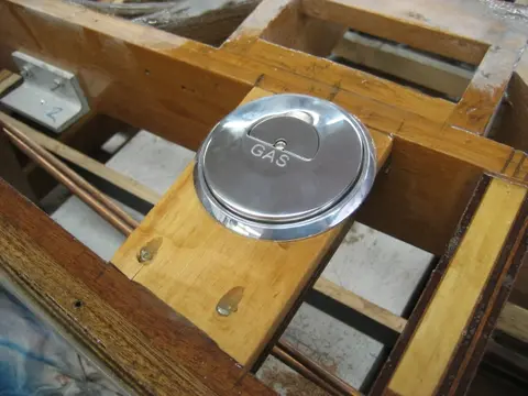
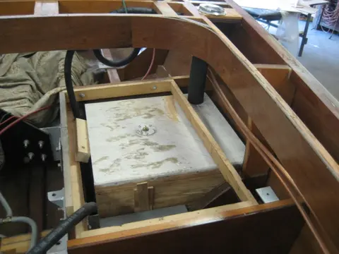
2. A stainless steel 2" fuel fill will feed the 9.2 gallon fuel tank. The white plywood box is a mockup of the tank. Also visible in the photo are the hydraulic steering's annealed copper tubing lines. It's a very tight installation !
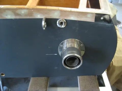
Hose barb will take a 3/4" hose. Also visible in this photo are the two 3/8" annealed copper tubing hydraulic steering hoses. They're retained by bulkhead fittings bolted through the steel transom support uprights.
... and the fuel fill hose.
1. A 1-1/8" hole saw was used to install the two bilge pump thru-hulls.
2. The large white box is a plywood mockup of a 9.5 gallon fuel tank. A 2" fuel fill hose can be seen on the right of the photo. A 5/8" fuel vent hose with a high coiled loop is on the left.
3. Here's a better view of fuel vent hose...
4. The vent hose was routed...
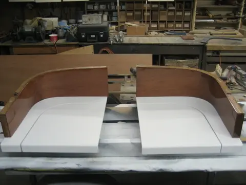
1. We built up the jumpseat's leading edge with a piece of 1" x 2" stock and radiused the top edge before laminating both sides with 10 ounce fiberglass cloth.
2. A stainless steel piano hinge will complete the assembly.
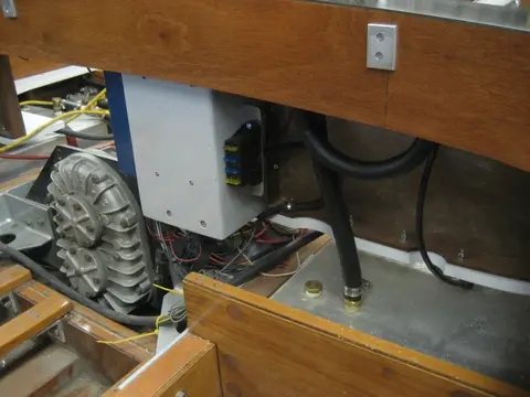
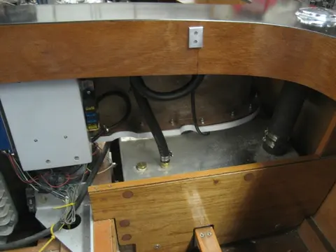
1. The 5/8" rubber fuel vent hose has been looped to form a high loop before its routed to the sheer mounted fuel vent fitting.
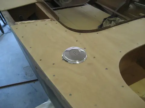
2. The 2" fuel fill hose is directly below the deck fill fitting.
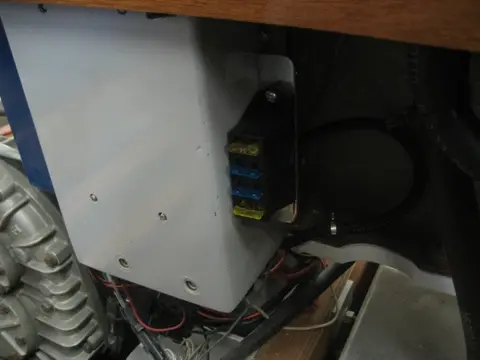
3. Here's a closeup shot of the unswitched 12 volt fuse block. This provides circut protection for the automatic bilge pump and any accessories that require unswitched 12 volt power.
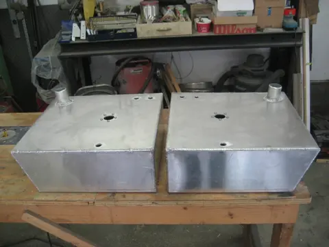
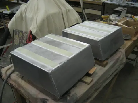
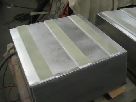
Our custom aluminum fuels tanks arrived on the 23rd. The 9 gallon tanks were fabricated at a local welding shop in Ottawa, Ontario. The tanks were on back-order for some time now. We've been holding off on final assembly until they were installed. Let the assembly begin !
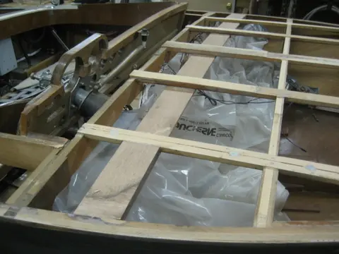
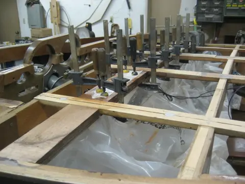
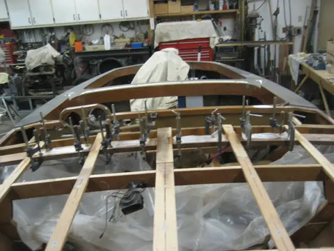
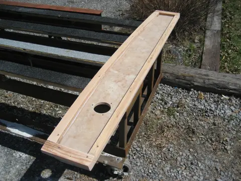
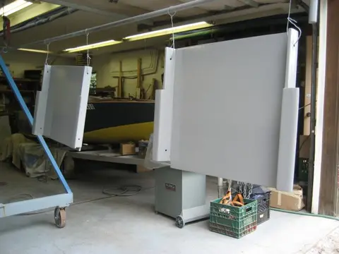
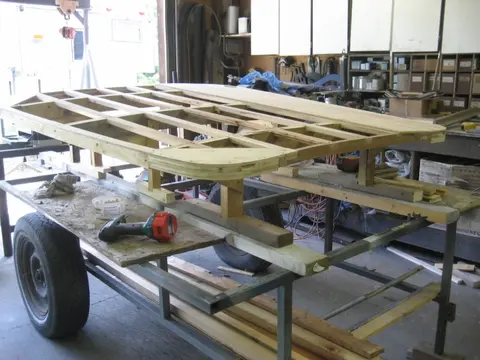
1. We've removed the tonneau cover from the boat and placed it on our trolley for sheeting and finishing. Corners were built up from from two pieces of 3/4" plywood molded to a width of 3/4".
2–3. Decking is 1/4" G1S exterior plywood.
4. The remaining sub deck panels were glued and screwed. We're ready for fiberglass !
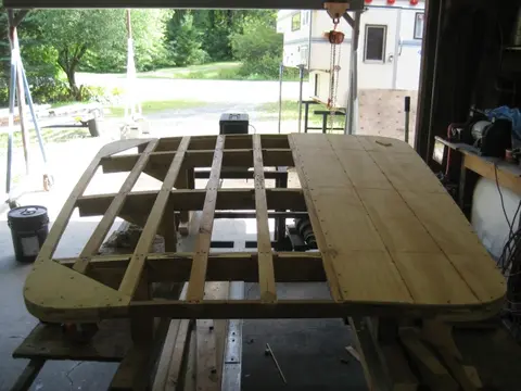
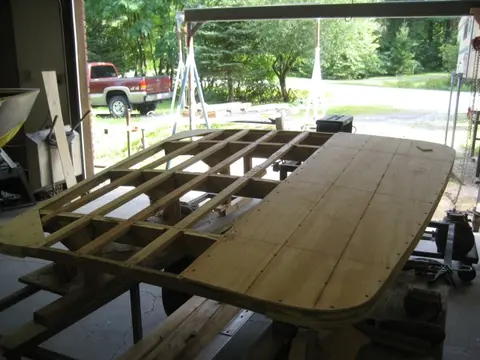
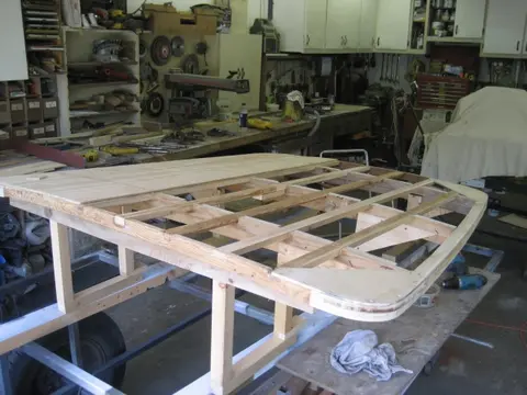
The remaining sub deck panels were glued and screwed. We're ready for fiberglass !
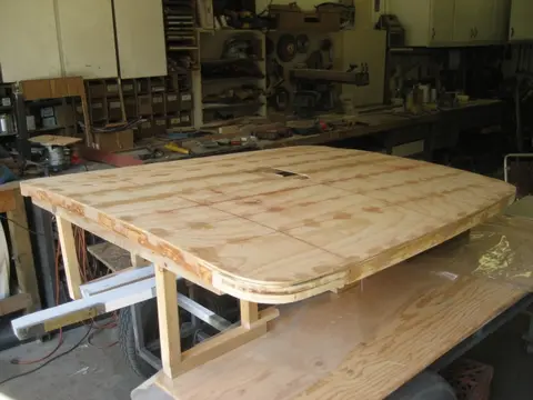
1. Six ounce cloth was applied with West System epoxy catalyzed with 206 Slow hardener.
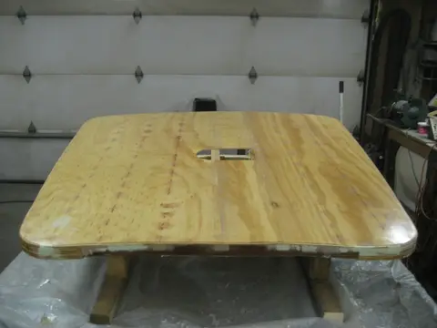
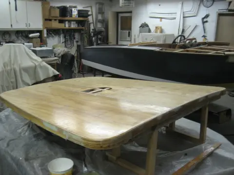
2. The cover is ready for first sanding and weave fill coats.
1. We'll be installing the fuel tanks using David Pascoe's method. Complete instructions are included in this article: How to Install an Aluminum Fuel Tank. The 1/4" thick fuel tank mounting pad was fabricated by laminating a fiberglass sandwich consisting of 6 layers of 2 ounce chopped strand mat between two layers of 6 ounce cloth. Once cured, we cut the composite into 2" wide by 16" strips.
2–3. Tank bottom was roughed up with 40 grit sandpaper, washed down with Wash & Wipe wax, grease and silicone remover, The strips were bonded to the ta...
1. Time to finish up the front deck. We needed to build a wide deck beam to bolt the dash cowl to. We epoxied a 4-1/2" wide strip of 1/4" marine grade plywood to the bottom of the deck battens.
2. We laminated three layers of 1/4" marine ply to conform to the deck beam's curvature.
3. The pop-up bow light mounts in a plastic housing (at left of photo). The fit wasn't too good, the plastic was very flimsy and the bolt holes were way too close to the edge, so we fabricated a wood plug from some scrap wood (middle of photo). We wrapped the plug with Saran Wrap and wetted out three l...