Hot Rod · step
Strongback & Molds
Building the strongback or ladder frame and setting up station molds.
Strongback & Molds on every boat, not just the Hot Rod →
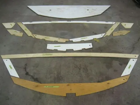
1–2. Frame templates completed. The half-plans were expanded to full size 3/8" plywood templates. This reduced layout and cutting time and increased accuracy and symmetry.
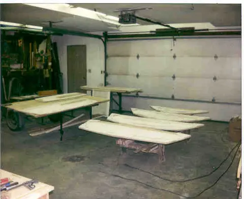
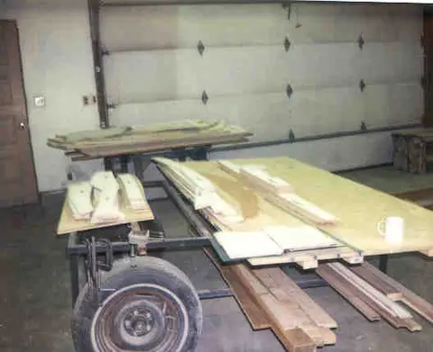
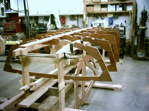
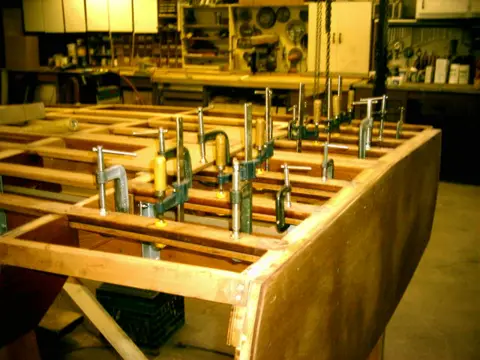
1–2. Full size mockup bottom frames 0 through 4 completed. Mostly scrap lumber (spruce, pine, plywood) was used to build the mockup frames.
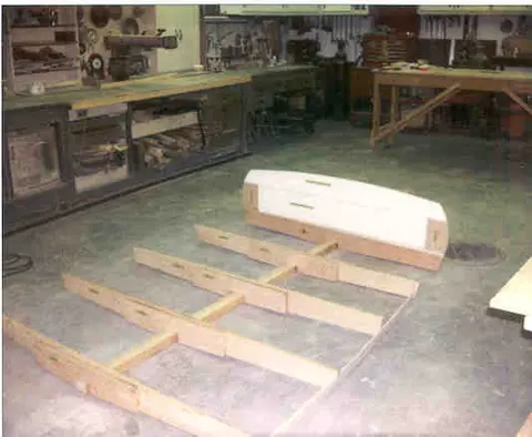
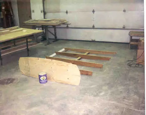
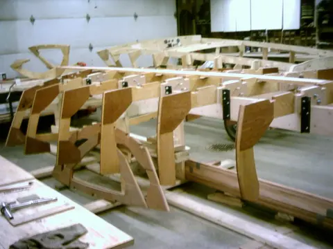
1. Installing mockup frames 0 thru 4 on motor stringers.
2. Work has come to a halt as we had to undergo eye surgery. Expected recovery time is about 5 weeks.
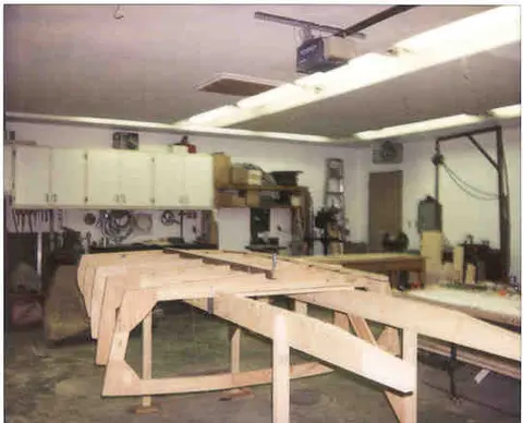
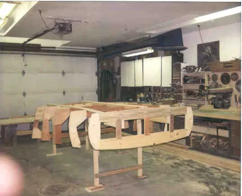
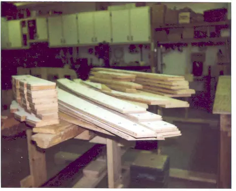
The templates for the bottom frames, laminations and floor timbers were screwed to Douglas Fir stock and cut on the bandsaw to within 1/8" of the template. Pieces were then trimmed on the router table using a trim bit.
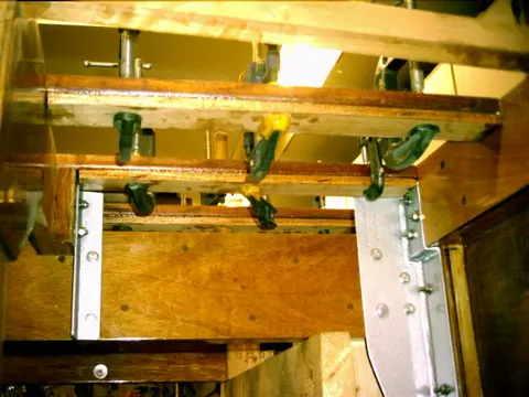
1–2. Frame clips were fabricated from 1-1/2" angle iron. The floor timbers were bolted to the frames which were in turn bolted to the motor stringers.
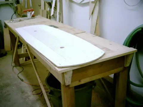
3. To ensure assembly accuracy, the transom pieces will be overlaid on the transom template.
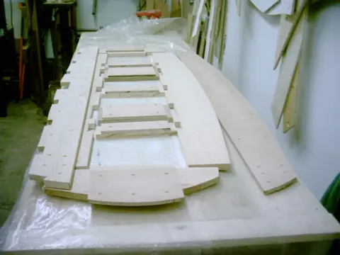
4. All pieces ready for lamination.
5–6. Filling the screw holes.
7–8. Drilling holes for the transom brackets.
9. Transom brackets were fabricated from 1/8" flat stock.
10. Bracket top was flared to allow the installation of two bolts instead of one.
11–12. Three coats of epoxy complete the transom.
13. Transo...
1. Installing the sheer clamps. Two strips of 5/8" x 1-1/4" mahogany will be used per side.
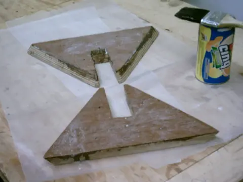
2–3. Although not detailed in the plans, the chine blocking was made from two pieces of 3/4" marine plywood. The sides were bevelled at 30 degrees and a notch was cut to fit around the stem. This is definitely a trial and error project. Much time will be saved when fitting the chine logs to the blocking.
4. Glued...
5. Screwed...
6. Installed.
7. The chine log was wrapped with waxed paper to prevent it from being glued to the blocking.
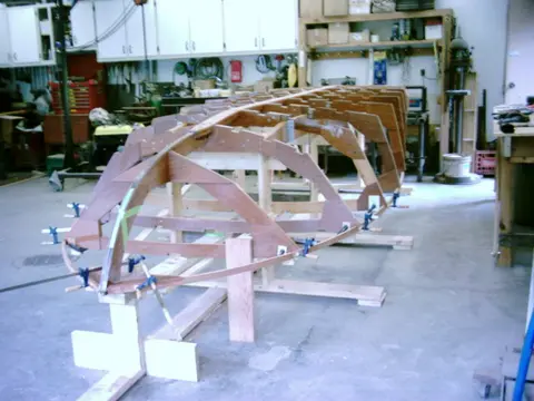
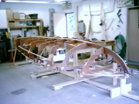
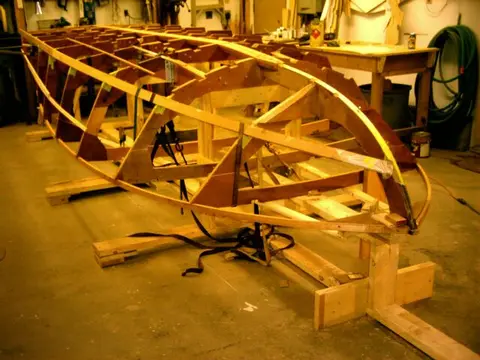
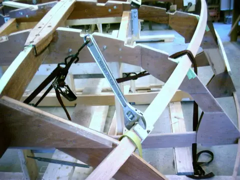
1. A large crescent wrench and a ratchet strap was used to twist the top of the chine inward towards the keel. Laying a straightedge from the sheer to the chine will indicate when sufficient twist is attained.
2. The second sheer clamp laminations are yet to be installed.
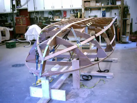
1. Gluing the third sheer clamp laminations.
2–3. Transom plywood (3/8" marine) installed.
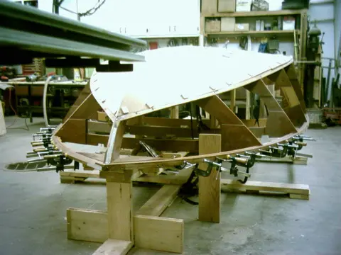
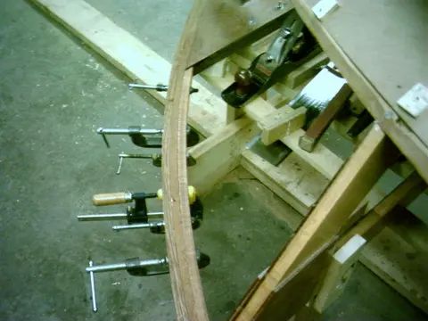
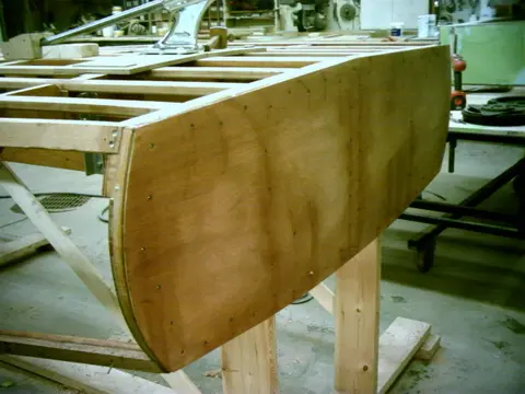
1–2. Two layers of 3/8" thick by 2" wide mahogany stock were laminated to the inside chine log surfaces. This will restore some strength to the members, lock the frames into position and provide additionnal fastening area for the first plywood bottom screws.
3. A 3/8" thick lamination was added to the rear battens. We'll be cutting 3/8" deep limbers (drainage channels) so additional material must be provided to maintain the batten's integrity.
4. Here's the view from inside the boat.
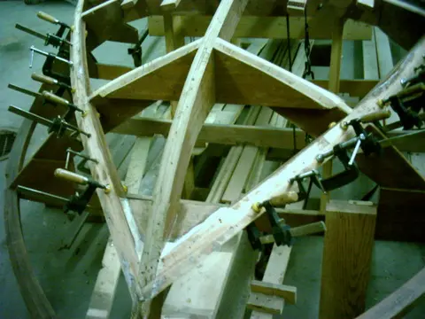
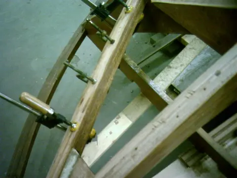
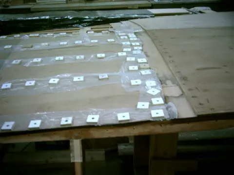
Prior to panel removal, keel, chine, batten, and butt block locations were traced with a pencil from inside the boat. Areas not to be covered with epoxy were taped off. The taping is extra work but saves a lot of cleanup time ! Epoxy was applied to both mating surfaces and allowed to set for several minutes. West System 403 adhesive filler was added to the catalyzed epoxy and spread over the mating surfaces. To aid fastener removal from the panel once the epoxy cures, strips of plastic film were slid under the plywood washers.
1. Once we got the control rod back from the machine shop, the turnbucles were trial fitted.
2. Now to cut the foot pedal control rod, thread the end to accept the clevis end and mark the control rod for the 1/4" wide keyway.
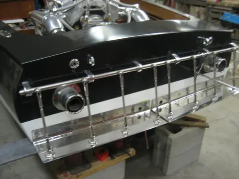
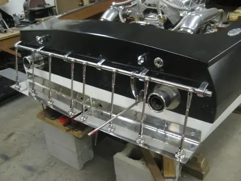
1. The cavitation plate is fastened to the transom with 5/16" x 3-1/2" stainless steel button head machine bolts. Every second bolt hole was overbored to 1/2" and filled with an epoxy and West System 403 filler.
2. A 1/4" hole was bored slightly above the bolt hole. The thickened epoxy slurry was loaded into a syringe and pumped into the bolt hole. Once cured, the cavitation plate was reinstalled, a 5/16" drill bit was used to locate the mounting holes.
3. Here's an excerpt from the Glenwood Marine Catalog explaining how the cavitation plate override system works: "On high speed...
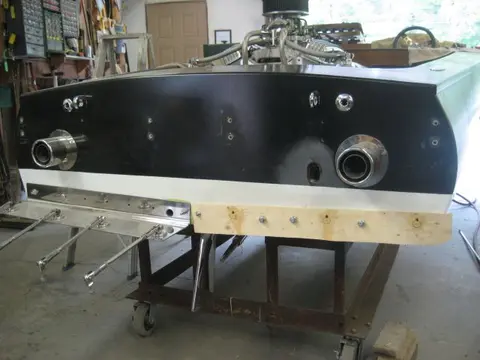
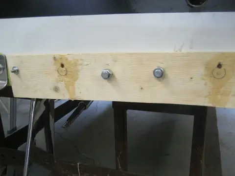
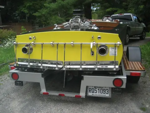
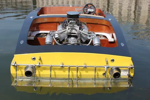
Latest Updates It has been a while since our last update ! We've been busy installing an adjustable cavitation plate on the boat. The installation required pulling the starboard fuel tank and fabricating a new shaft to mount the cavitation plate pedal and gas pedal. We also shot some Corvette Yellow on the transom while we were at it. We hope to have the boat back in the water early next week. We'll be leaving September 3rd for the 1200 mile ride to the 2012 edition of the Glen-L Boatbuilder Gathering at Lake Nickajack, Tennessee, September 7-9 2012. Click here to see the cavitation plate ins...

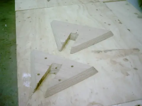
At the bottom of the photo, you'll notice another set of templates. These are for a 1/4" marine grade plywood lamination which is bonded to the frame before the frame gusset are added. This will prevent the frame lumber from splitting and adds more strength, as the lamination overlaps the frame joints.
Here's a photo of the completed frames and floor timbers.
The following photos describe how we produced frame templates for the Glen-L Hot Rod. We might be building more than one boat, so developing the templates may save a ton of layout work if we ever build another one. Click on any photo fo...
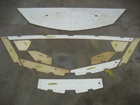
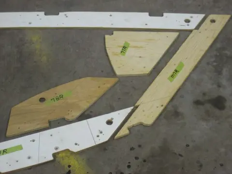
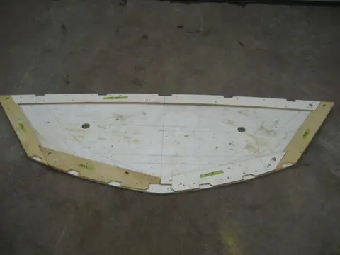
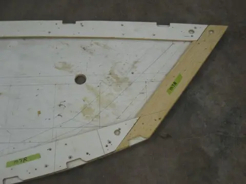
Since there was a possibility of building more than one boat in the future, we produced a set of frame templates to improve construction accuracy and save layout and production time on subsequent boat builds. Click here to learn more about the frame templates.