boatbuildlog

Glen-L Squirt · new build

Glen-L Squirt

by George · Greece · Message George
Make a book Feed The whole log, 26 entries and every photo, laid out as a book to print, bind and keep.
26
Entries
371
Hours
1,858
Days elapsed
861
Photos
Spent
23.5 h Link

Finishing the hull, and painting (first attempt)

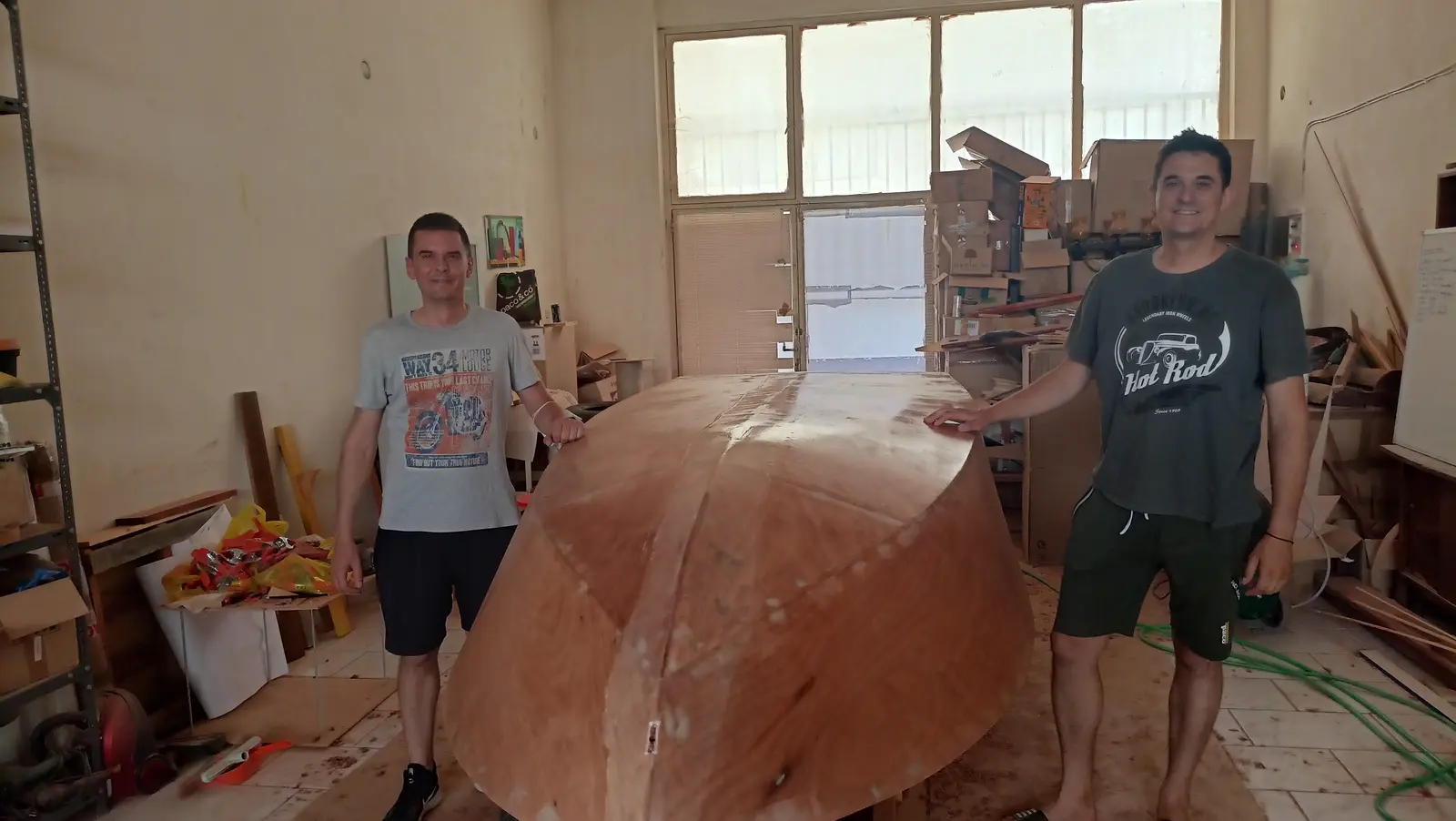
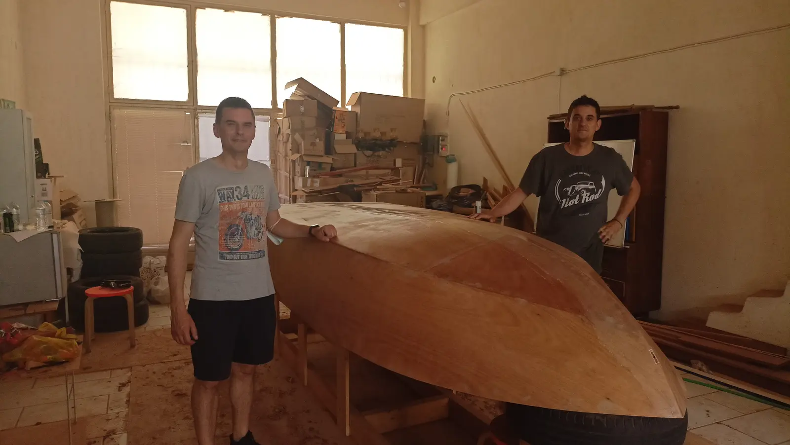
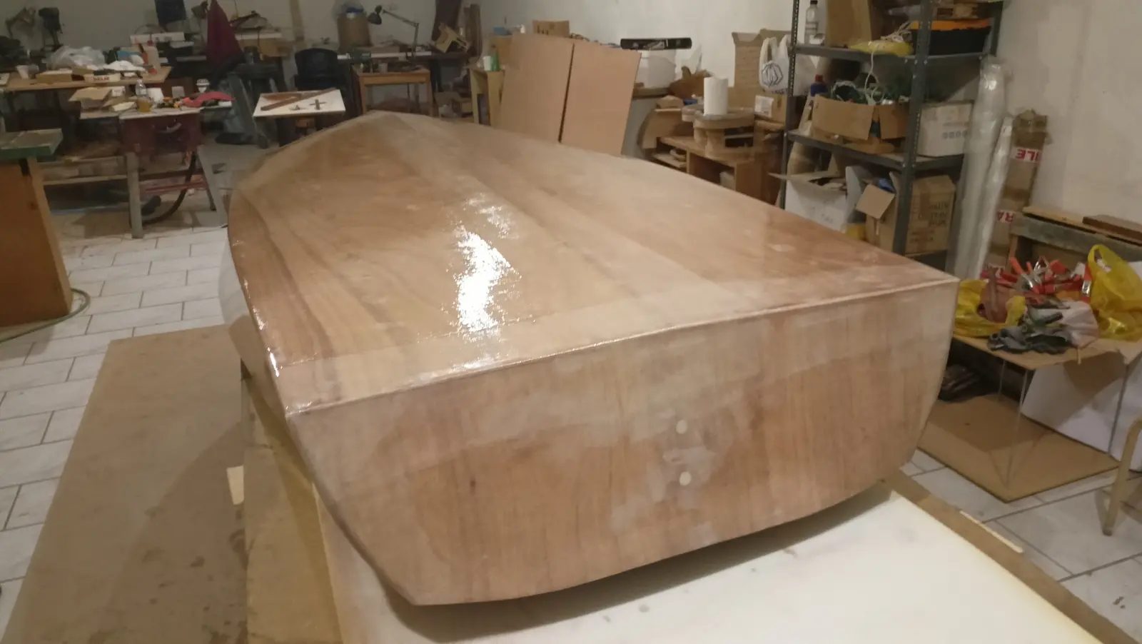
With the shaping finished all the way round the boat, it was time to turn it over again so the work on the hull could be completed. That means four more coats of resin, fitting the skeg, cutting the angle back into the transom to avoid the water cavitating (the joint had been rounded over so the cloth would stick), applying epoxy fairing filler for a perfect finish, then the epoxy primer and the topcoat. Two friends, Yannis and Iraklis, helped turn it over. The boat is still extremely light.

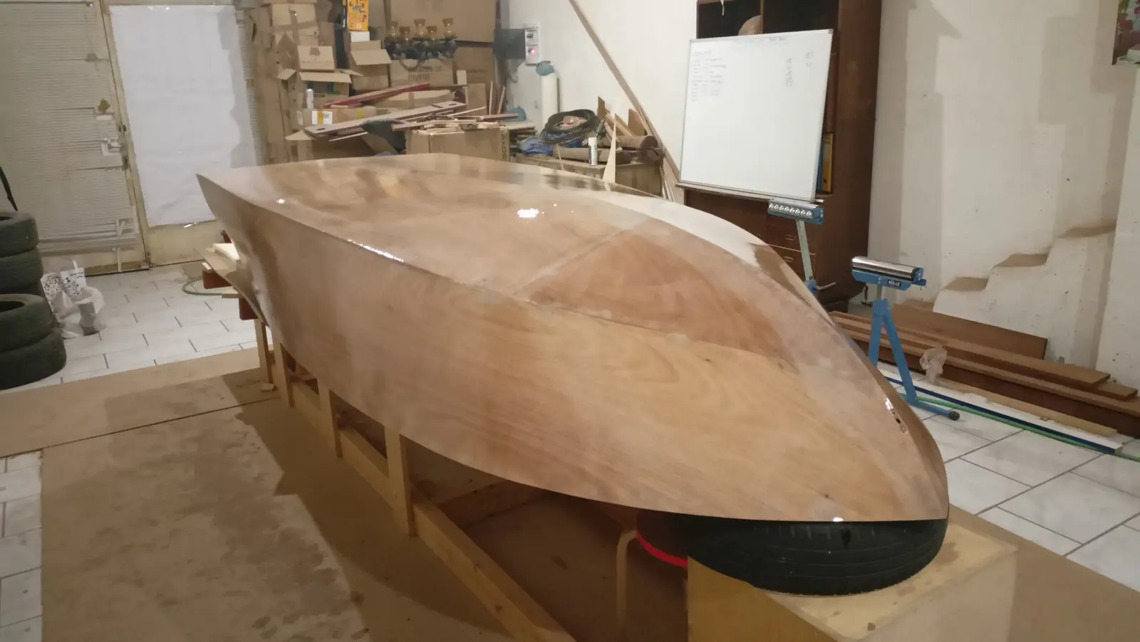
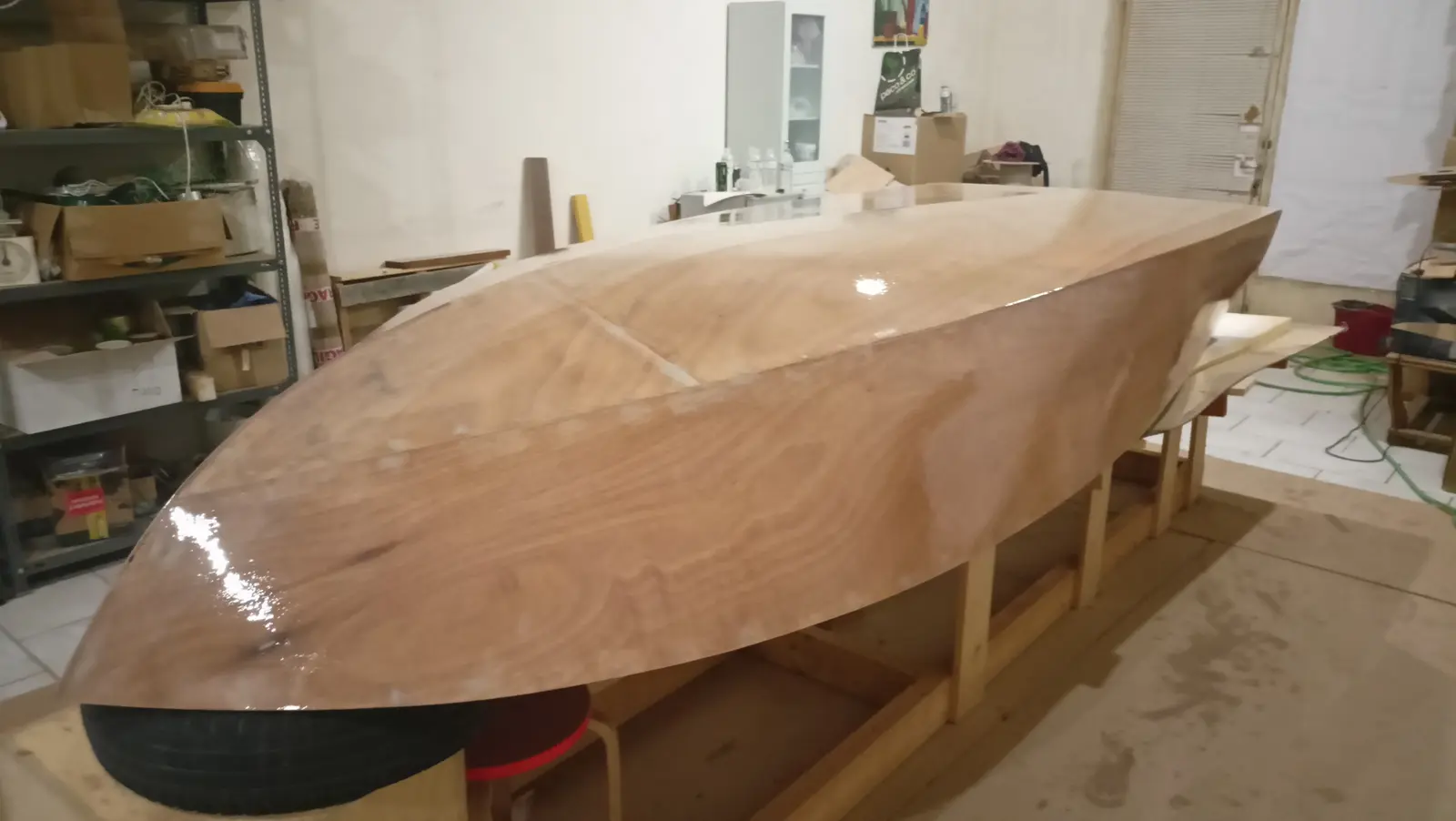
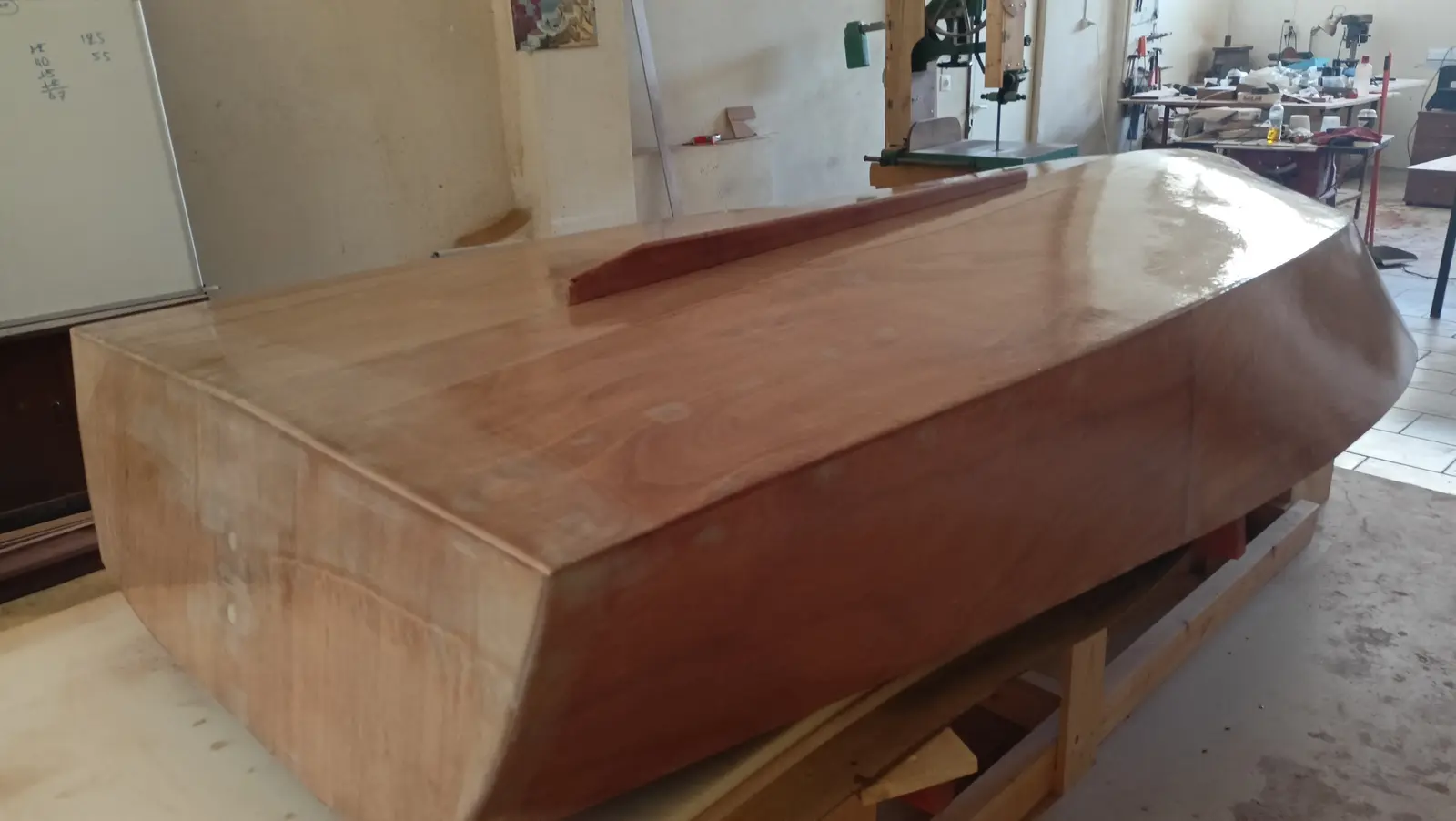
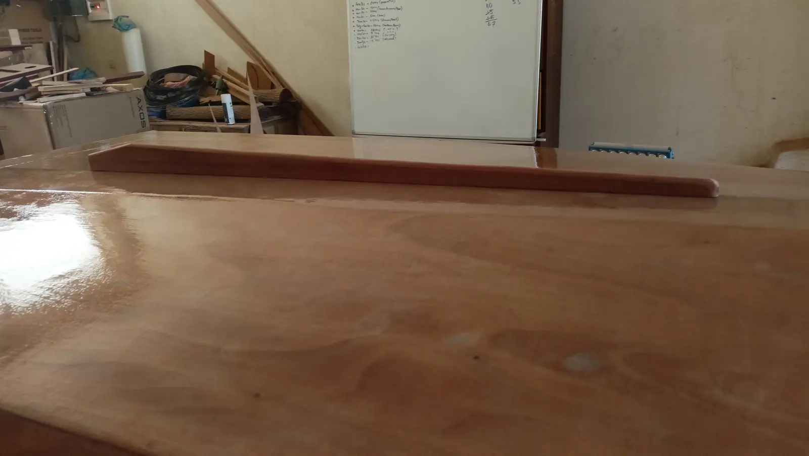
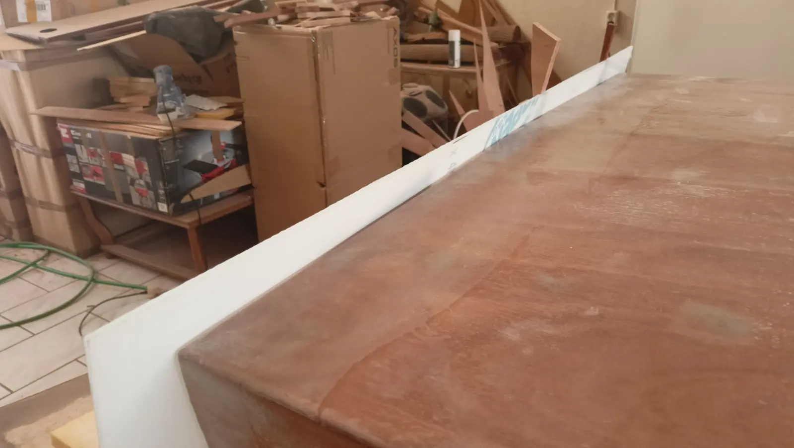
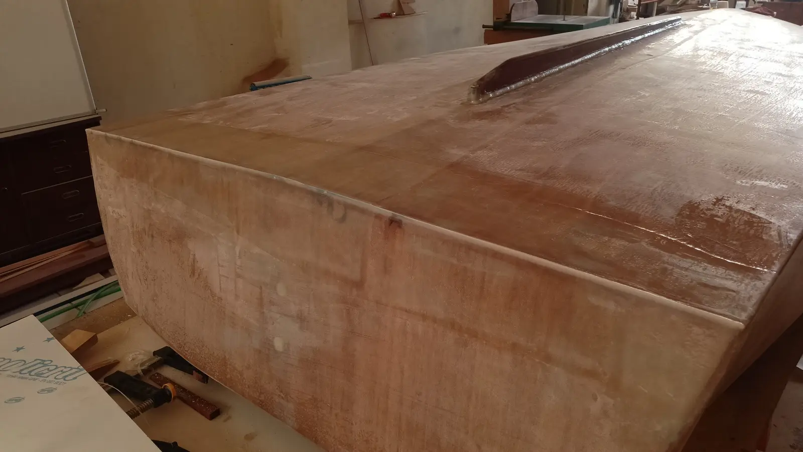
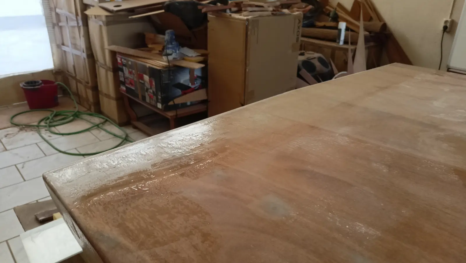
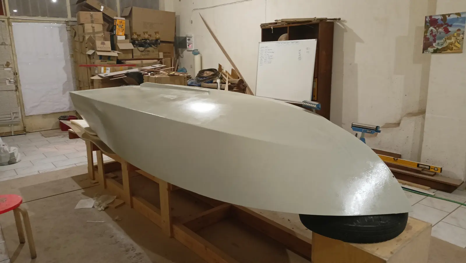
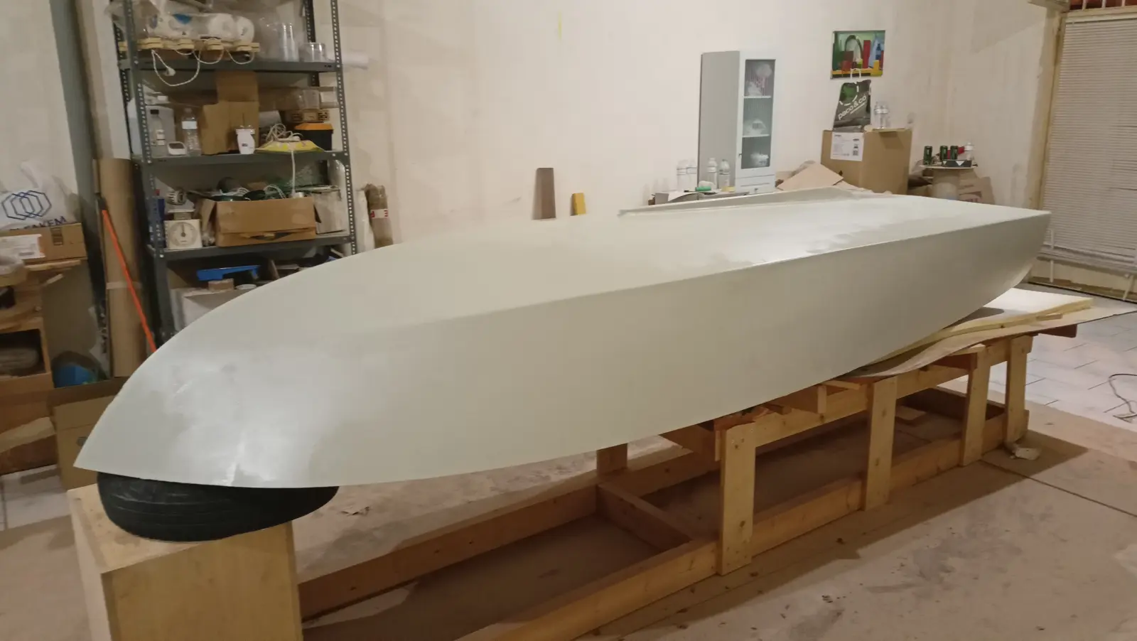
First the boat was cleaned with water and a Scotch-Brite pad to remove the amine blush that forms on the resin, which is water soluble. It was wiped down with kitchen paper. The 4 coats of resin went on in one day, 4 to 5 hours apart. Done that way there is no need to sand, and the bond is chemical as well as mechanical, since the resin has not set. Each coat took 350 grams. The resin was applied with a West System 800 roller. At the end, to help it lay off better and to break the small bubbles that form, I went over it again with the roller but without letting it turn, holding it at the ends and dragging it across the hull. The result that way is much better. Some photographs of the finished result.

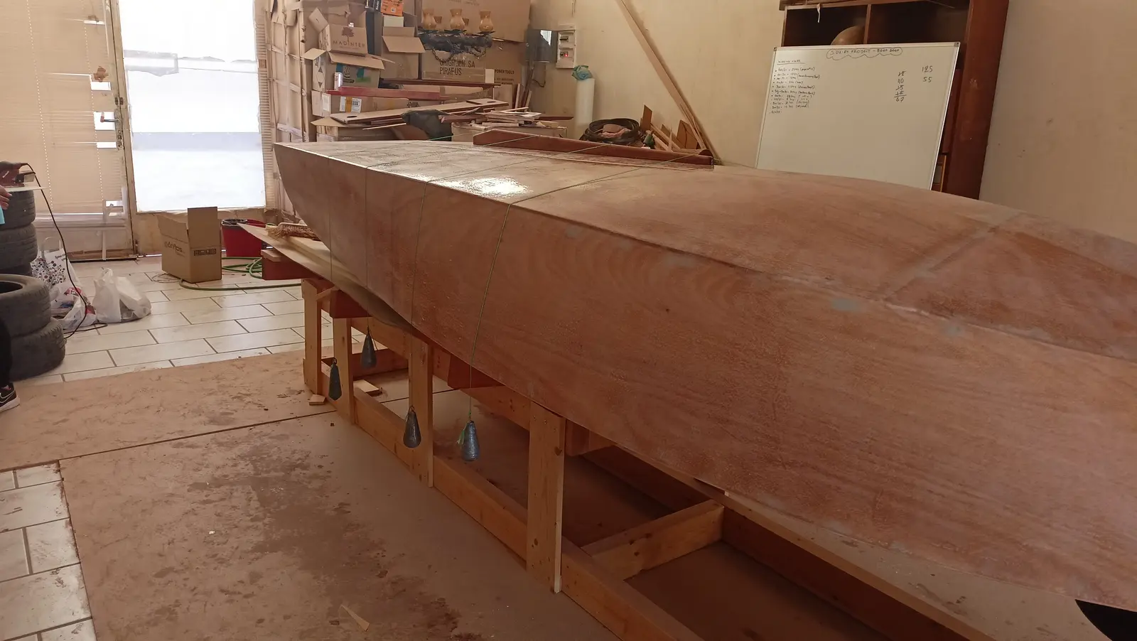
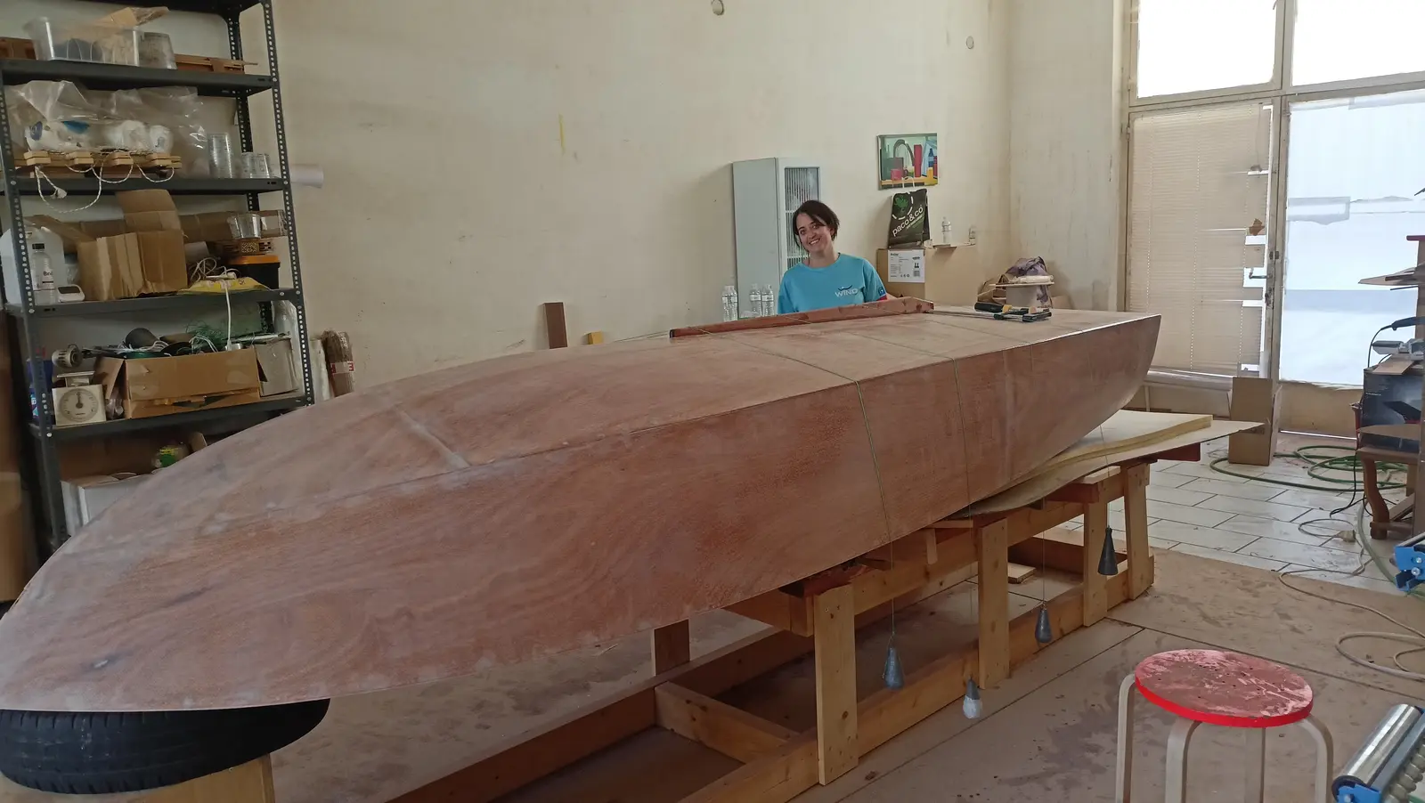
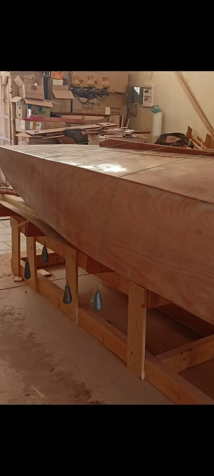
The next job was making and fitting the skeg. I decided to fit one so the boat would answer better to changes of direction. The skeg is 1.20 m long and its aft end is 60 cm from the transom. At the forward end it is about 1.5 cm deep and at the aft end 6 cm, dropping away slightly at the very end. To copy the curve of the hull the skeg was held in the right place and the curve was marked on it using a small block and a marker pen. It was then cut on the bandsaw. It was glued using string and weights to press it lightly against the hull. Some photographs below:

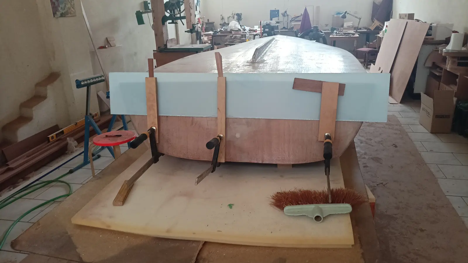
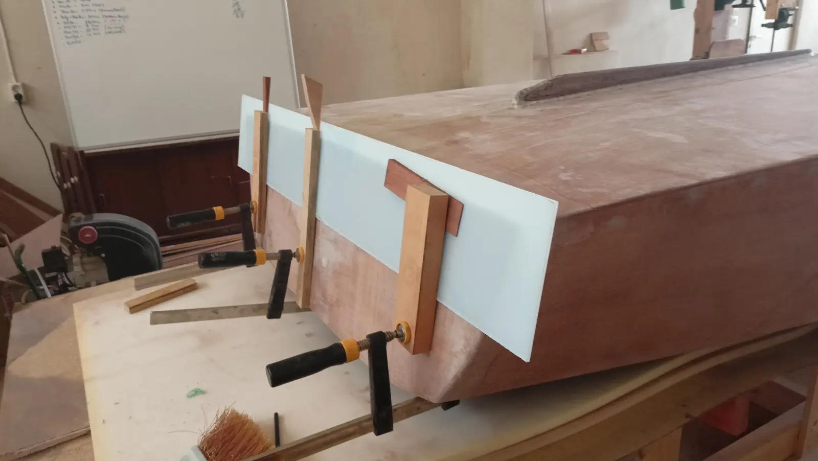
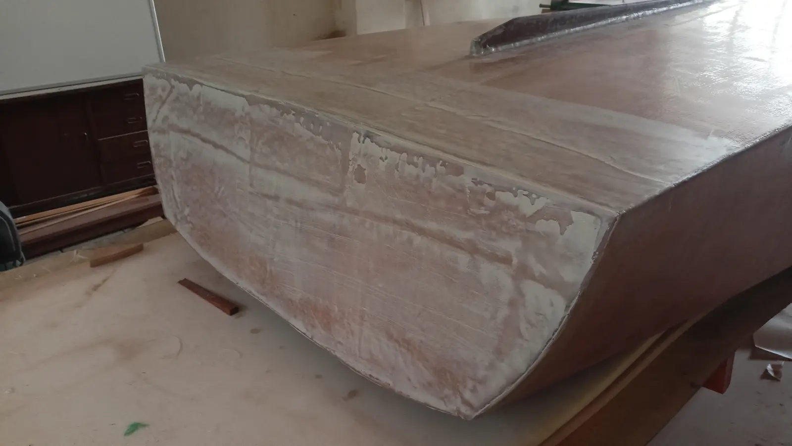
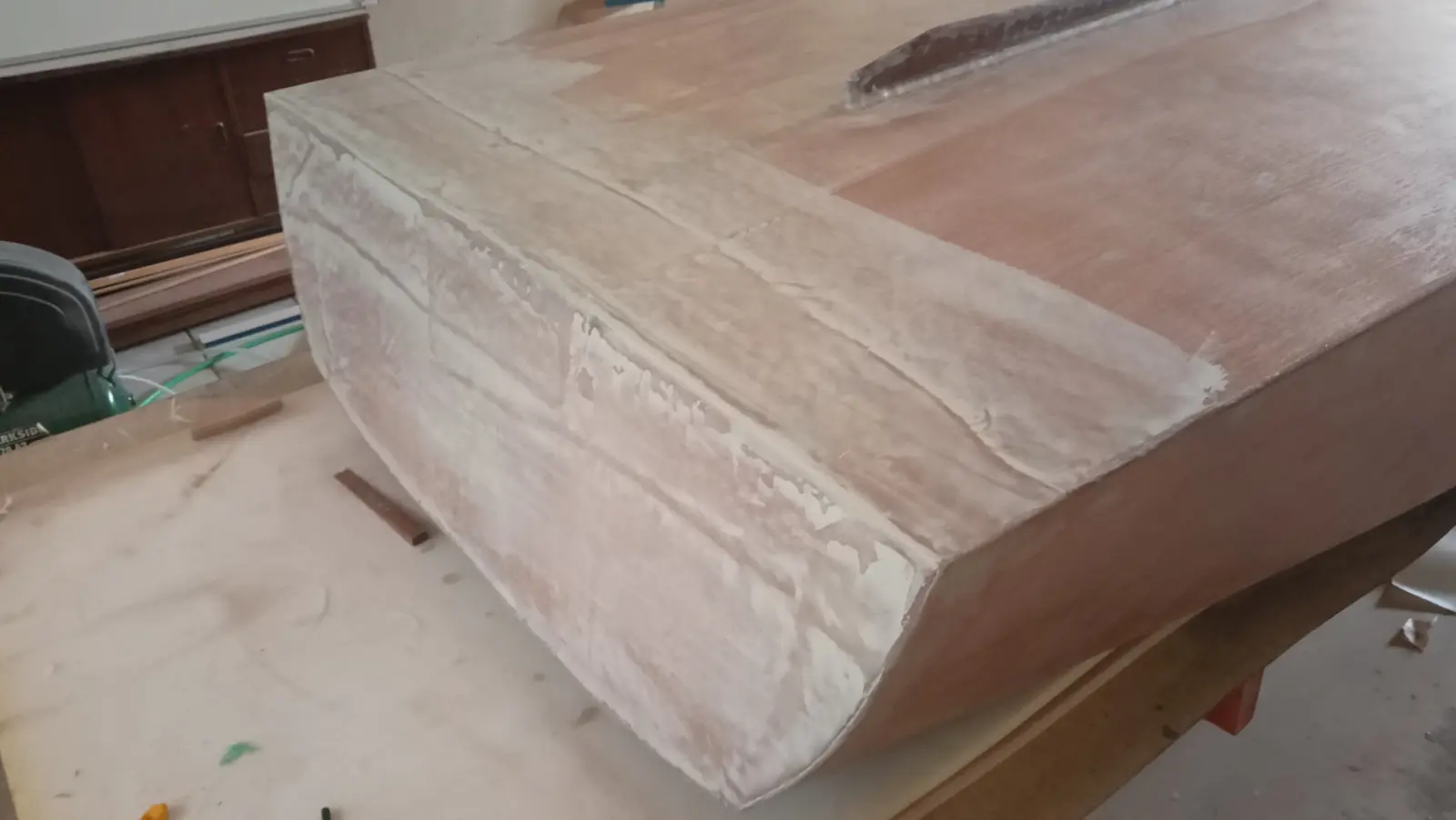
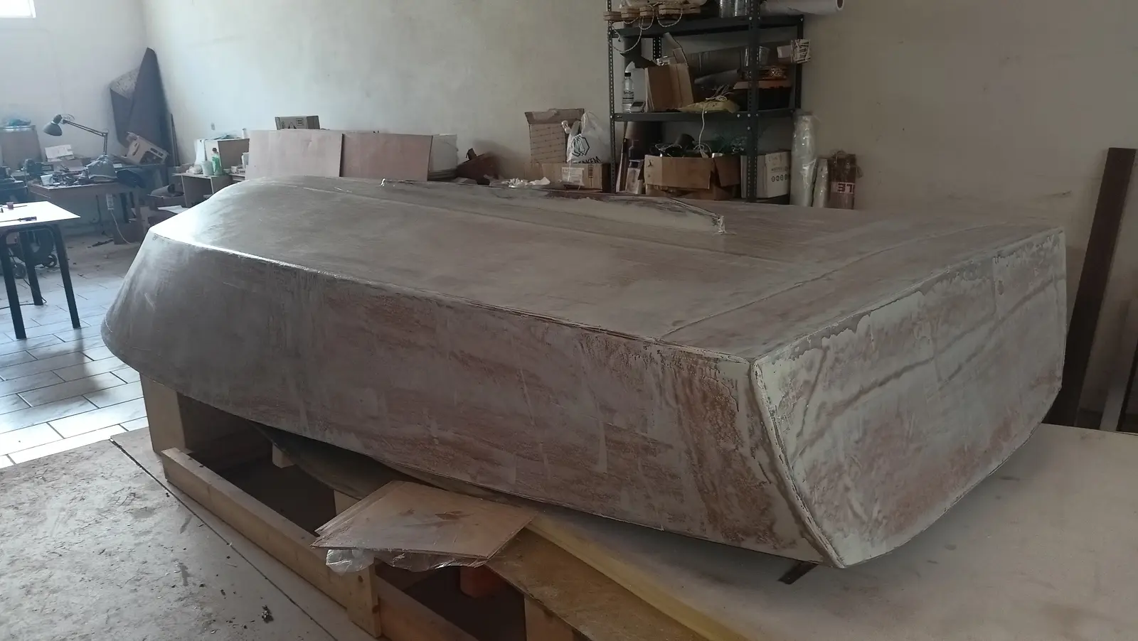
Along with the skeg, the joint between the transom and the hull was reshaped. To lay the cloth, a curved surface had to be created so it would stick down. That curved surface would cause problems though, because of water cavitation. So the angle was cut back in, in the way shown in the photographs below.

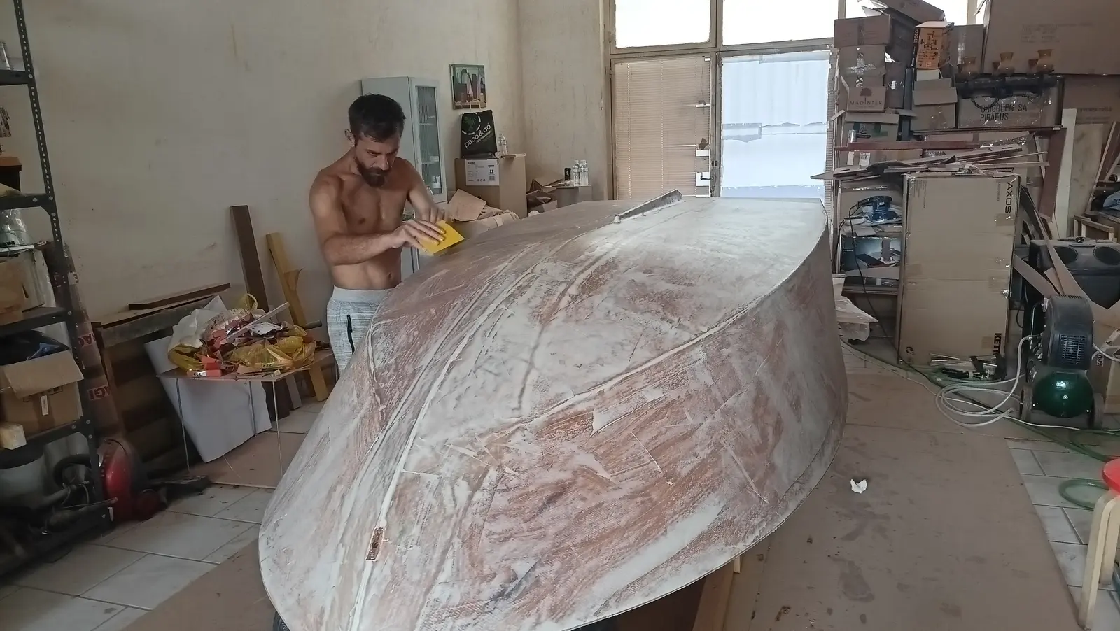
With that work done it was time to skim the whole hull with two-part epoxy fairing filler, to close up the last small imperfections left by the cloth. Perhaps another two or three coats of resin would have taken them out, but I think the filler will certainly make the job easier. If I had chosen to varnish rather than paint the sides of the boat, three coats of resin would have been the only option. I started at the transom, which has the worst of it and is a relatively small area, so I could do my testing there.

Two coats of filler went on, since after the first coat and sanding a few imperfections were left. After the second coat it was sanded again, paying a lot of attention to the details.

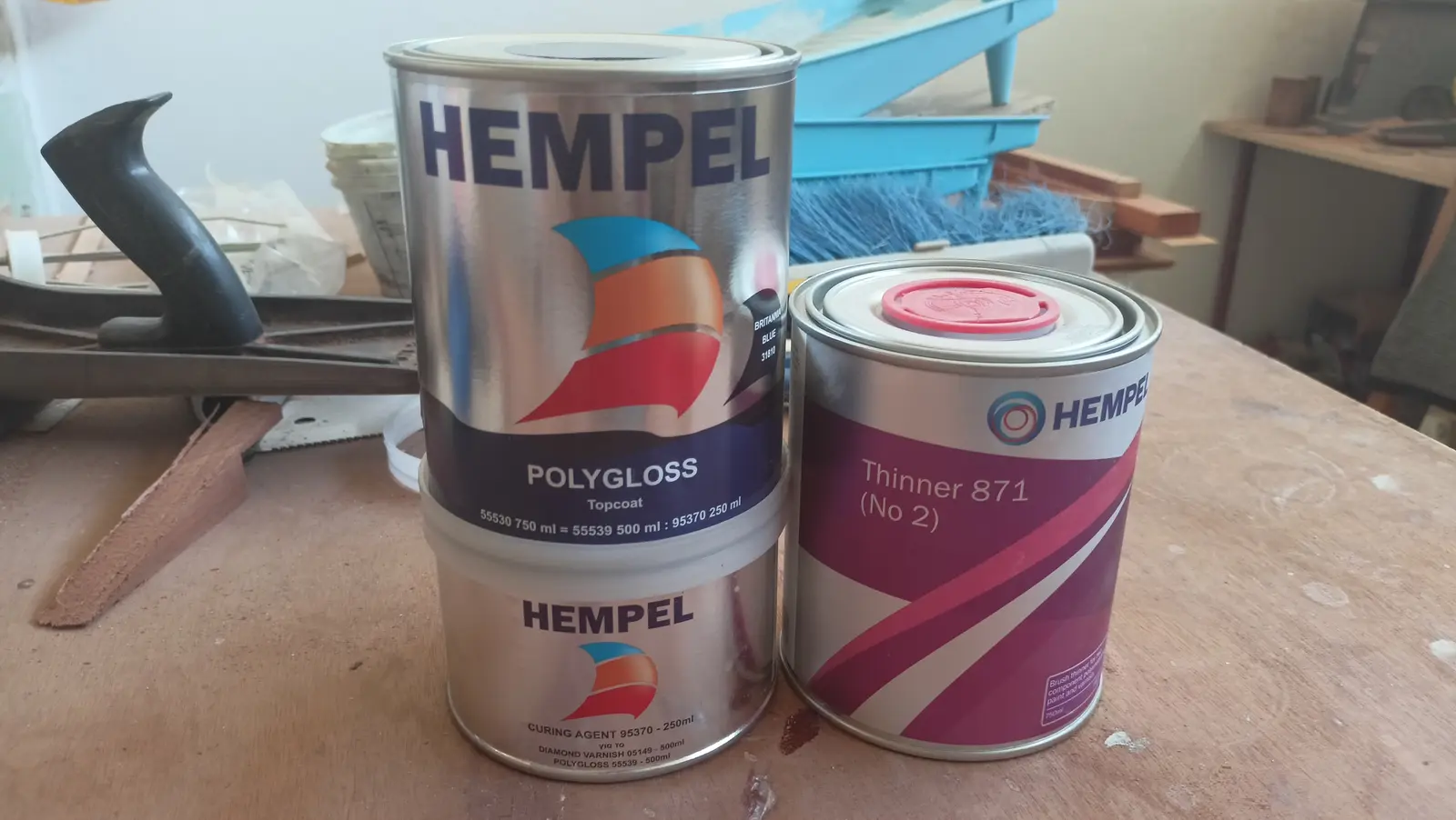
The hull was then washed with water and, once dry, cleaned with the thinner made for the epoxy primer. The whole 750 ml tin was used for the first coat of primer. Two percent thinner was added to the mix. Room temperature 26.5 degrees Celsius. Humidity 50%. Mohair roller.

Some photographs of the process, again with my friend Stratos, and the finished result:

The primer instructions say you have to wait 48 hours before sanding the surface. That presumably applies at lower temperatures, but I stuck to it. The whole surface was sanded with 240 grit and the second coat went on.

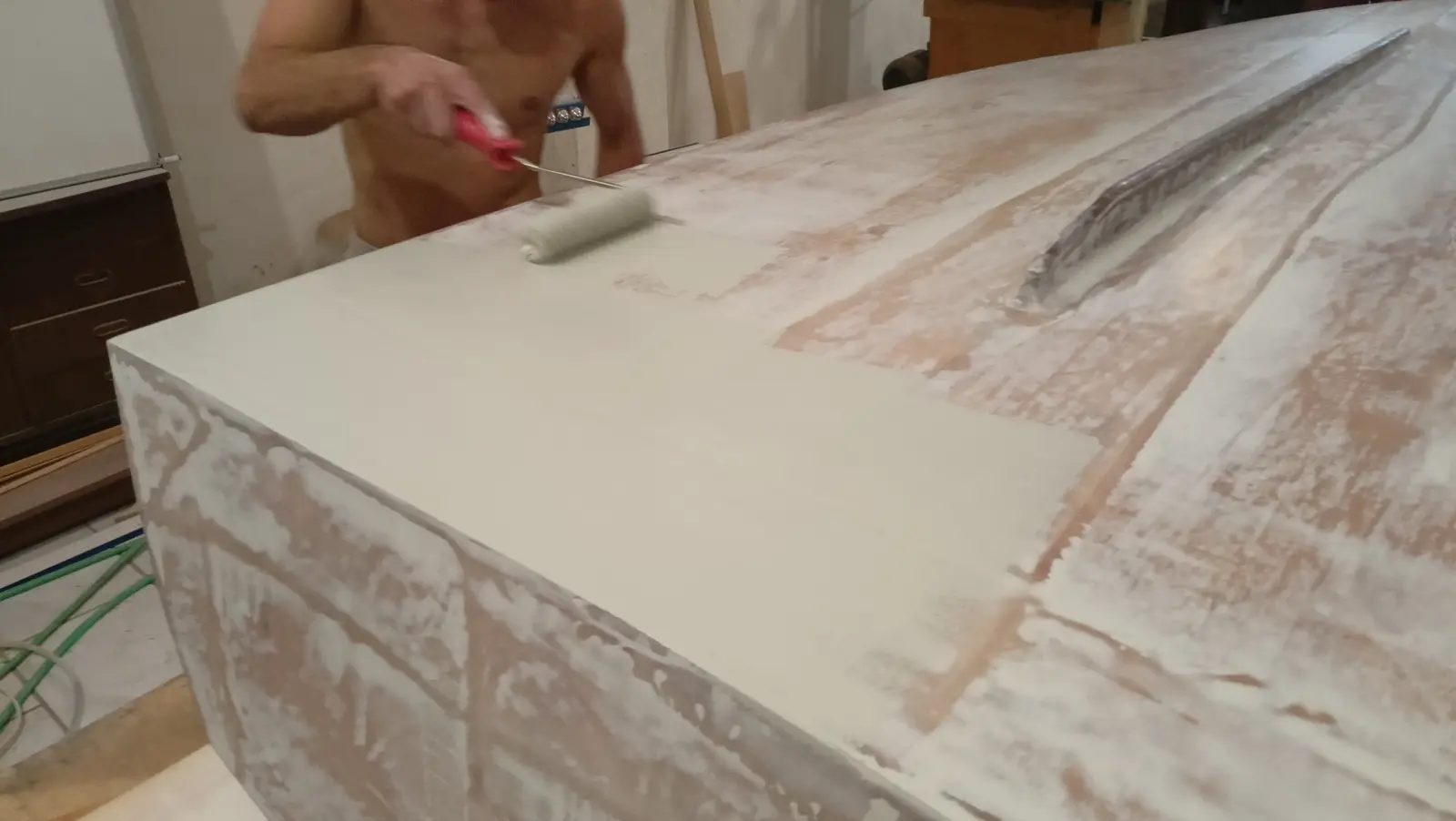
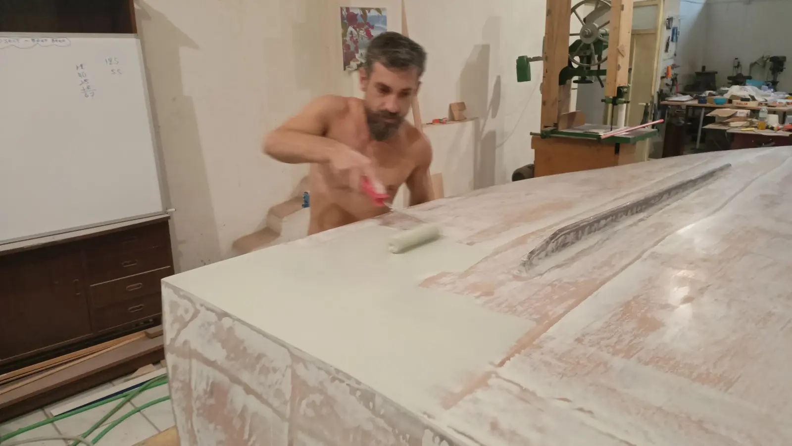
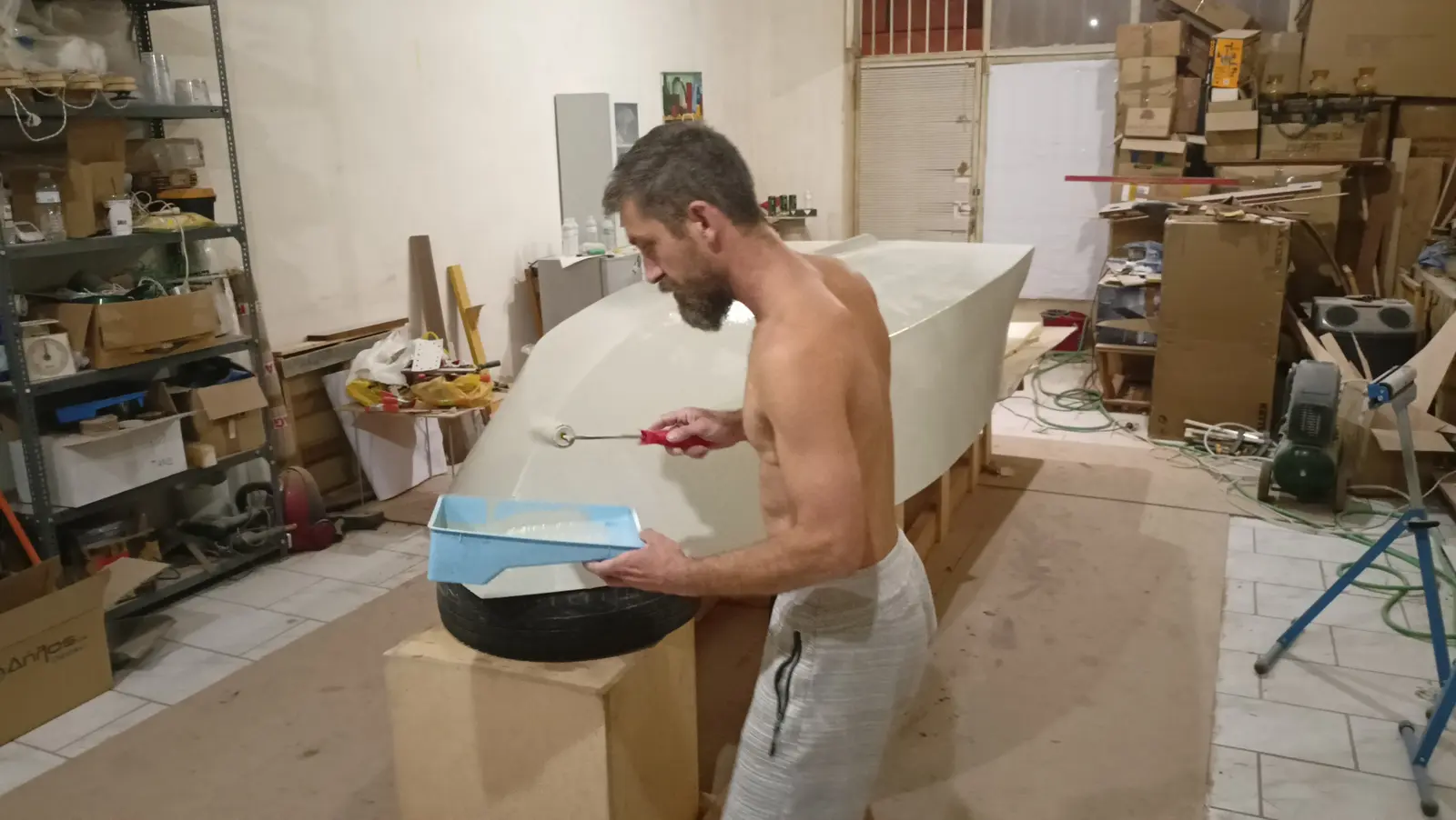
The primer was sanded again, this time with 320 grit, and the surface was prepared for the topcoat (washed with water and with the paint thinner). The colour is Epifanes Britannia Blue and it will go on with a polyurethane foam roller and then a brush (the roll and tip method). After rolling it on you go over it with very light strokes of a dry brush, and the result is much better. The video below shows the method.

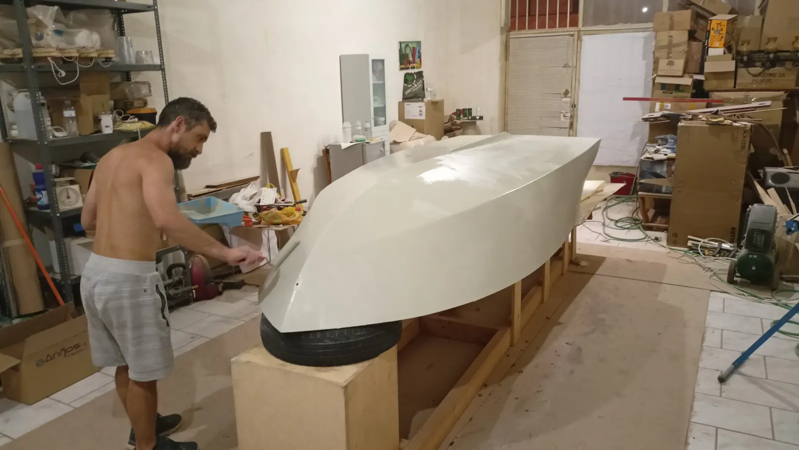
The result after the first coat is shown below.

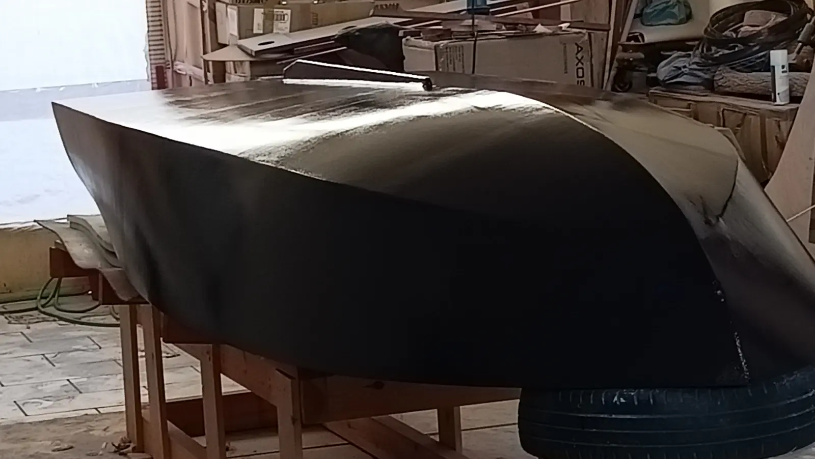
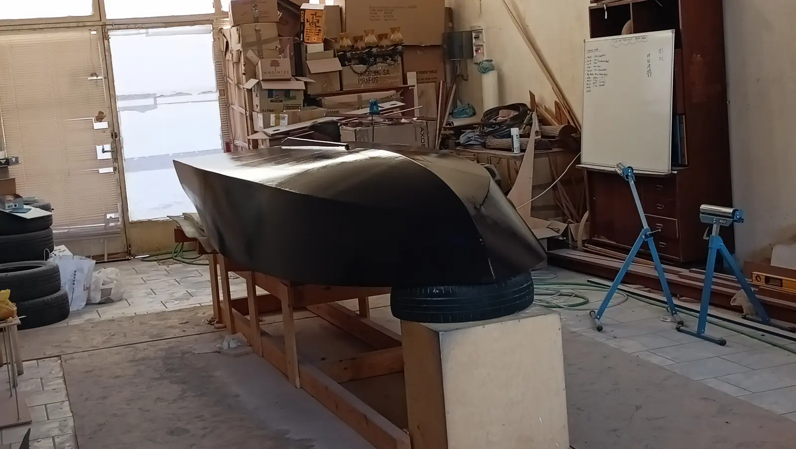
The result is utterly disappointing. Close up you can see a lot of bubbles that have formed in the surface. That may be down to how very hot the workshop was over the summer. Or perhaps that was not it at all and I did not have the thinning right. Whatever the cause, I hope to find out over the winter. I have decided to stop bothering with the painting. I will turn the boat over again and carry on with the work on the inside.

The materials used were:

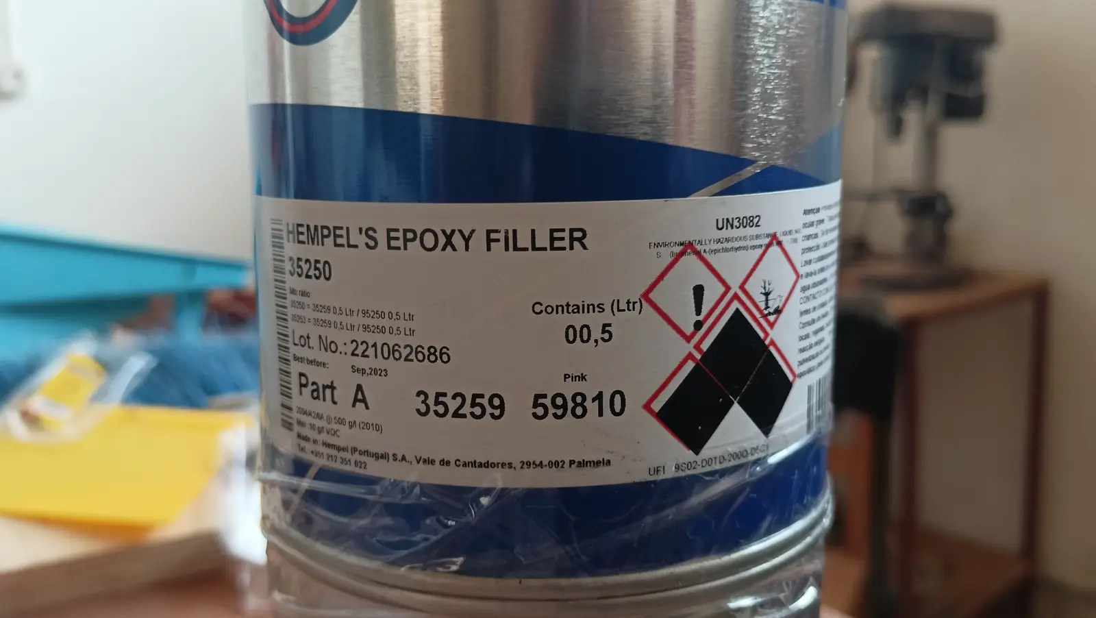
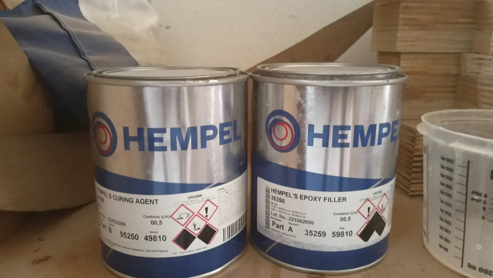
  • Hempel epoxy filler

  • Hempel light primer epoxy primer

  • Hempel Polygloss 55530 two-part polyurethane paint
8.5 h Link

Interior work No. 3

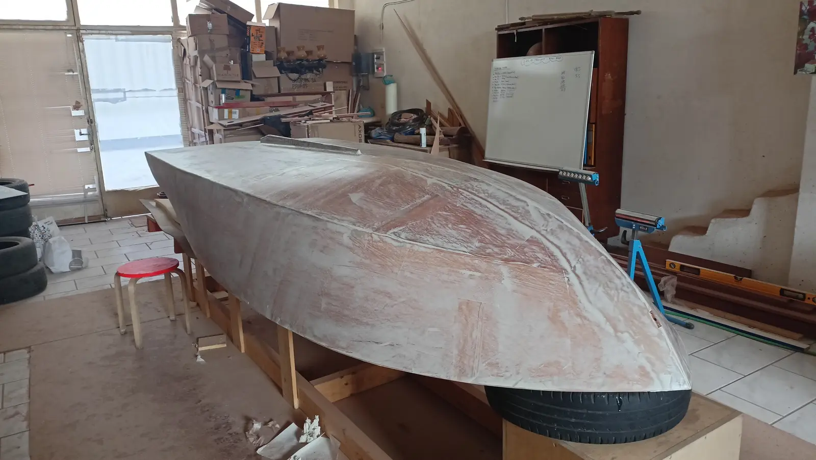
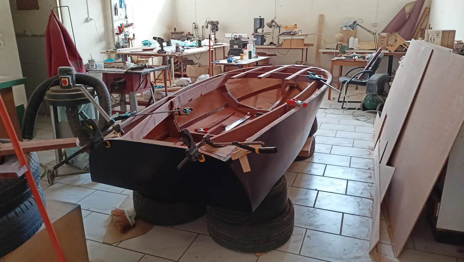
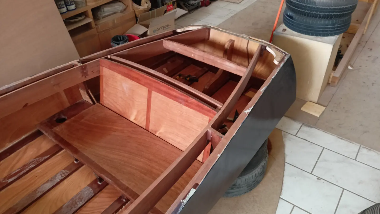
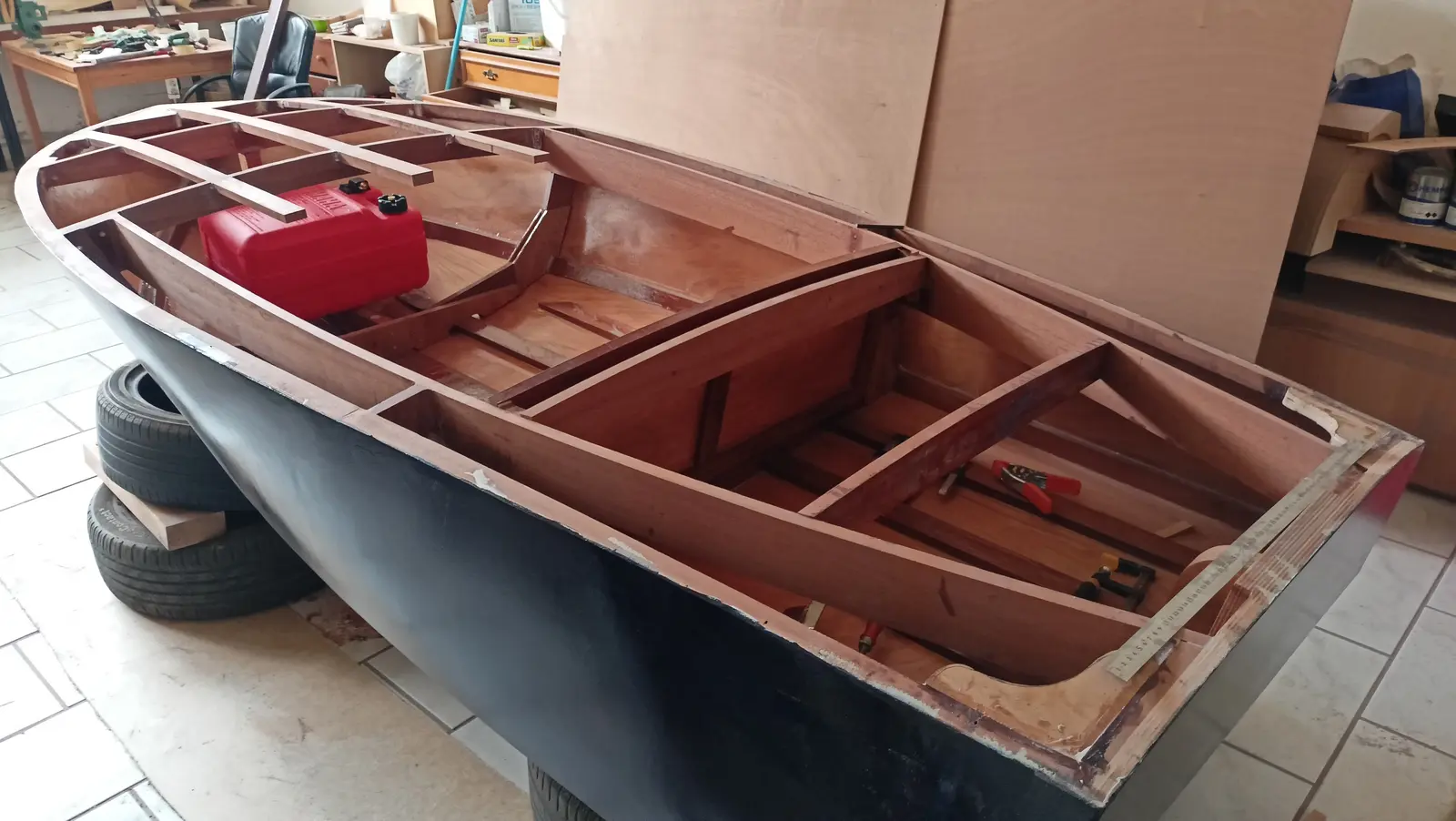
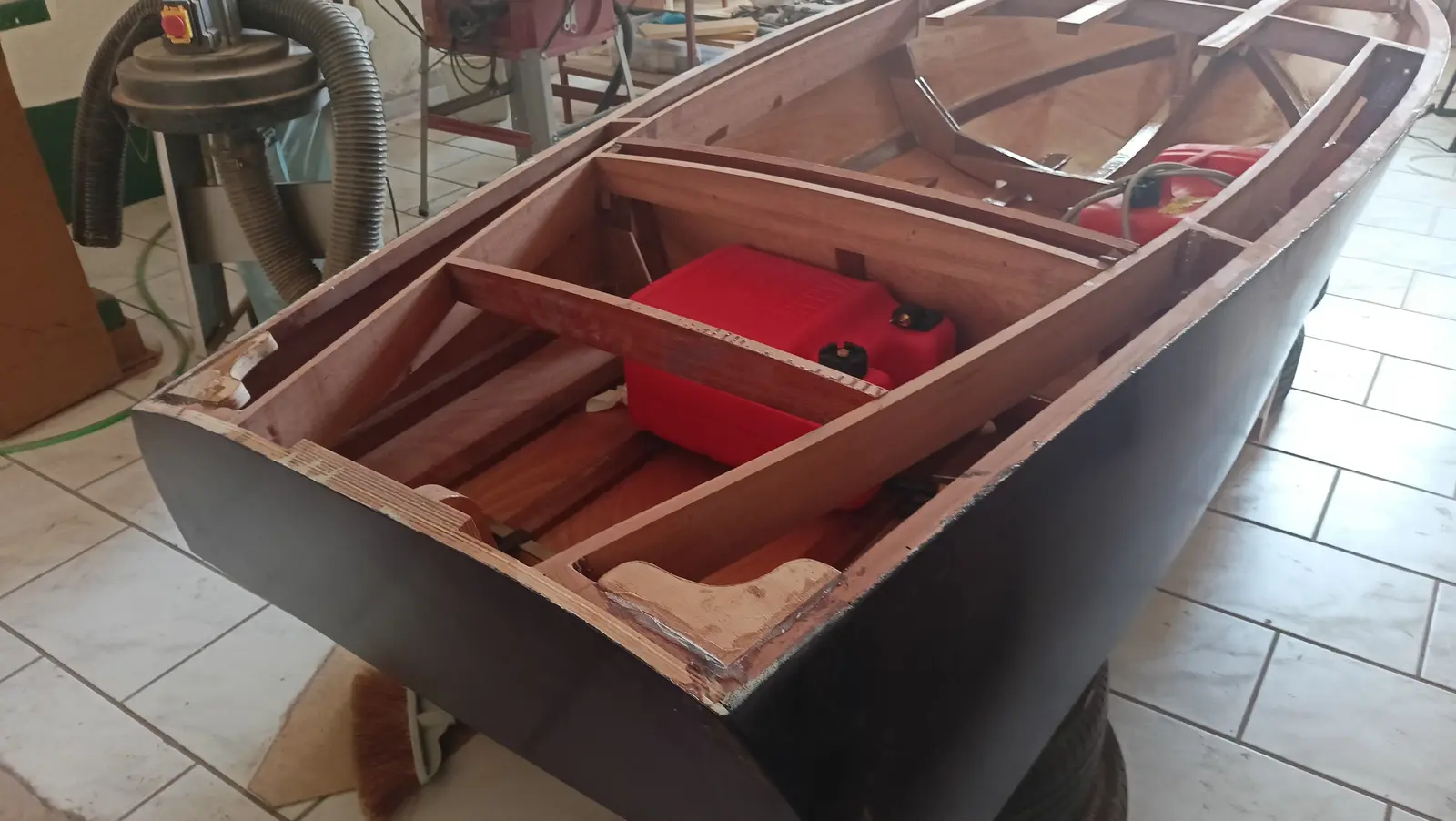
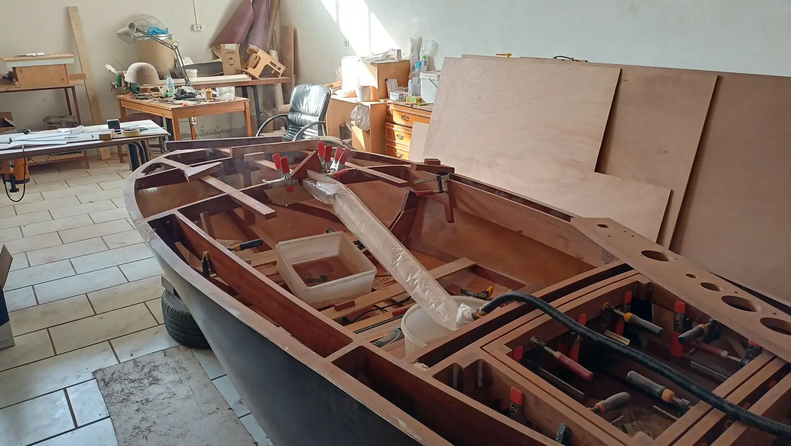
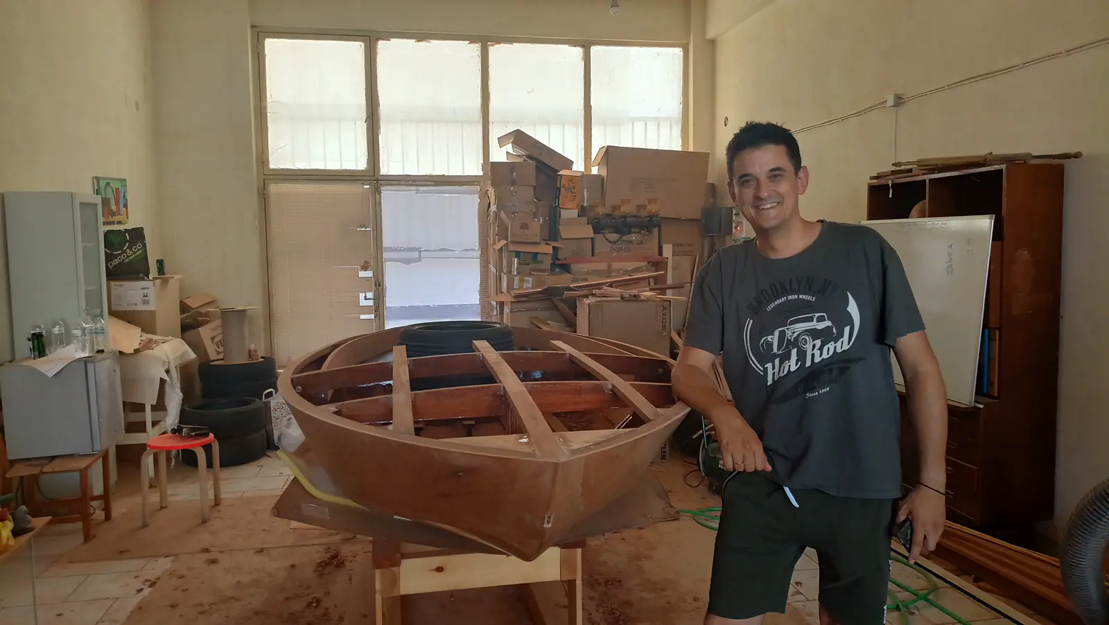
The boat has been turned over again. It was set down temporarily on car tyres, because to go back on the base that has to be modified now that the skeg is on. I will make it at some point and move the boat as soon as I can find company. Work can be done quite comfortably on the tyres anyway. It sits a little lower (I have used two tyres so it comes up a bit more) but the work goes reasonably comfortably.

The jobs to be done are gluing in the seat back and the timbers aft that will form the locker and the engine cutout. The uprights behind the seat back were cut, along with the last one before the cutout. That last one will not be glued until the engine is fitted, so I can see where it goes.

Some photographs below.

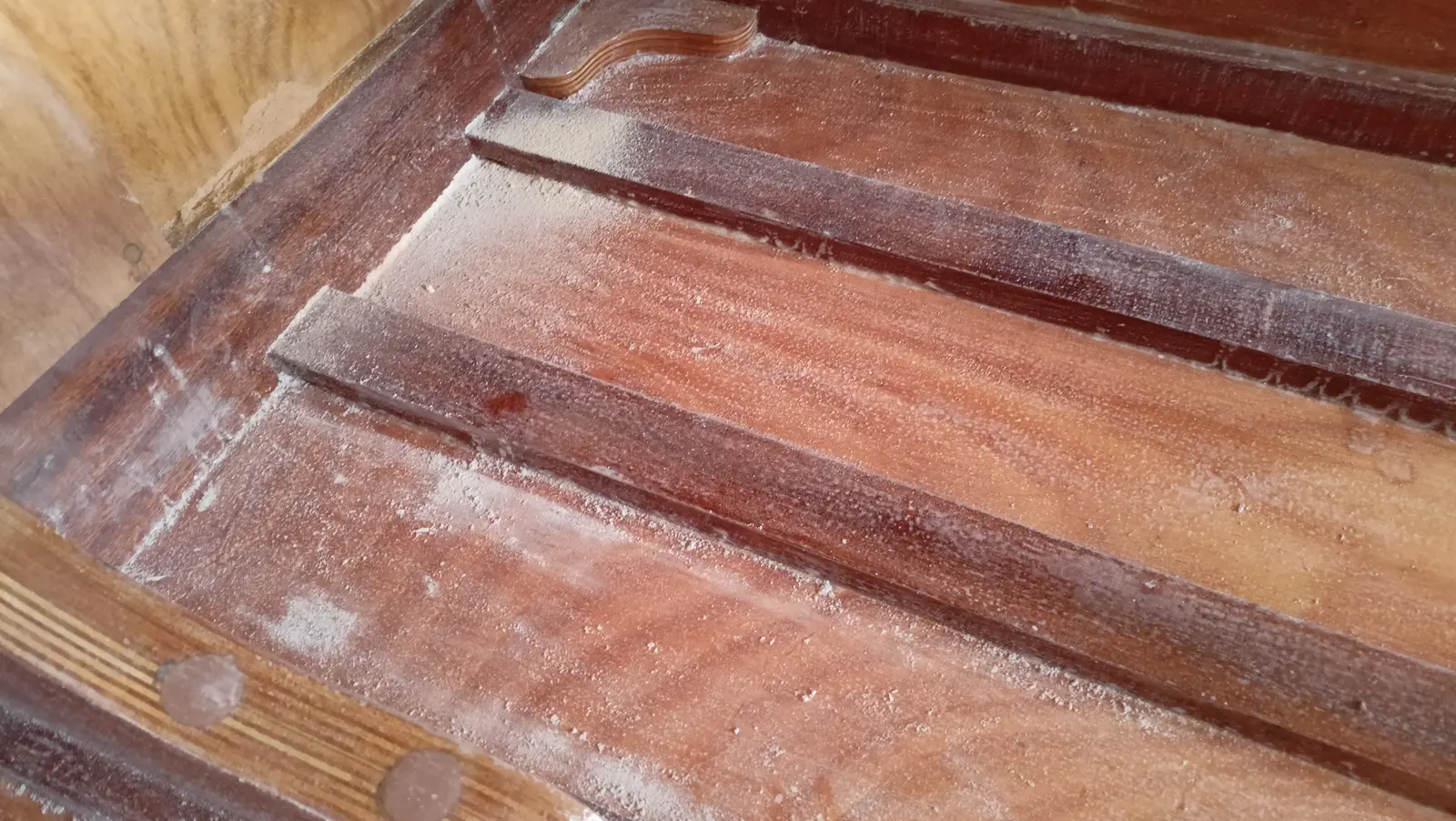
The next job was a second coat of resin inside. To do that, everywhere the first coat had gone had to be sanded. The resin will only go on the areas that will not be seen. The areas that will be seen will get the 207 hardener, which gives a far better looking result and has better UV protection. Obviously it needs varnishing afterwards as well.

The sanding was fairly punishing work...

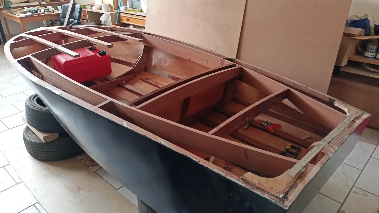
Another dilemma I have to settle is where the fuel tank and the battery will go. The problem is mainly their weight. If they go aft it increases the weight at the back of the boat and, combined with the heavy outboard, there may be a problem. If they go forward there will probably be a problem with vibration, and a new supply cable will definitely be needed (obviously a negligible problem).

After a lot of thought and asking other builders I decided to put it aft, but as close as possible to the seat back and away from the transom. The battery problem turns out not to be a problem, because the outboard does not need many cranking amps (CCA) to start. I found I can buy a lithium battery weighing about a kilo.

To glue the seat back in, I had to prime and paint the areas I would not be able to get to afterwards. They got two coats each.

The back was then glued in, after adjusting the height of the blocks it sits on slightly so it came to the right height.

The next job is gluing in the last timbers that will form the locker and the engine cutout. To decide the size of the cutout I would like to fit the engine, so as not to get any unpleasant surprises. Visually I think that if I split the locker and the cutout evenly it will look best.

The blocks that will reinforce the aft face of the locker were glued in, and then that piece itself, with the same curve as the other uprights.

All the remaining pieces were then cut. Both the ones that will form the locker opening and the locker lid itself.

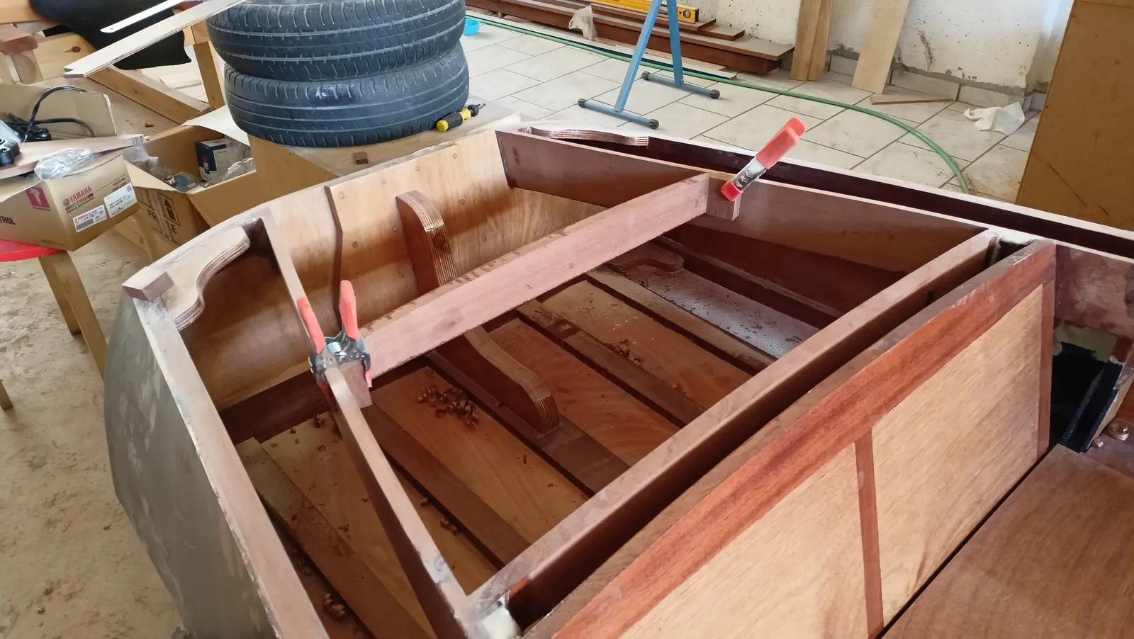
The photograph below shows the arrangement of the locker timbers. The two middle pieces are two because I have not yet decided how the locker will open.

I have two options:

  • One locker lid opening backwards

  • Two lids opening one to the left and one to the right. In that case I will cut the lid down the middle and have two leaves. That is why there are two pieces in the middle.

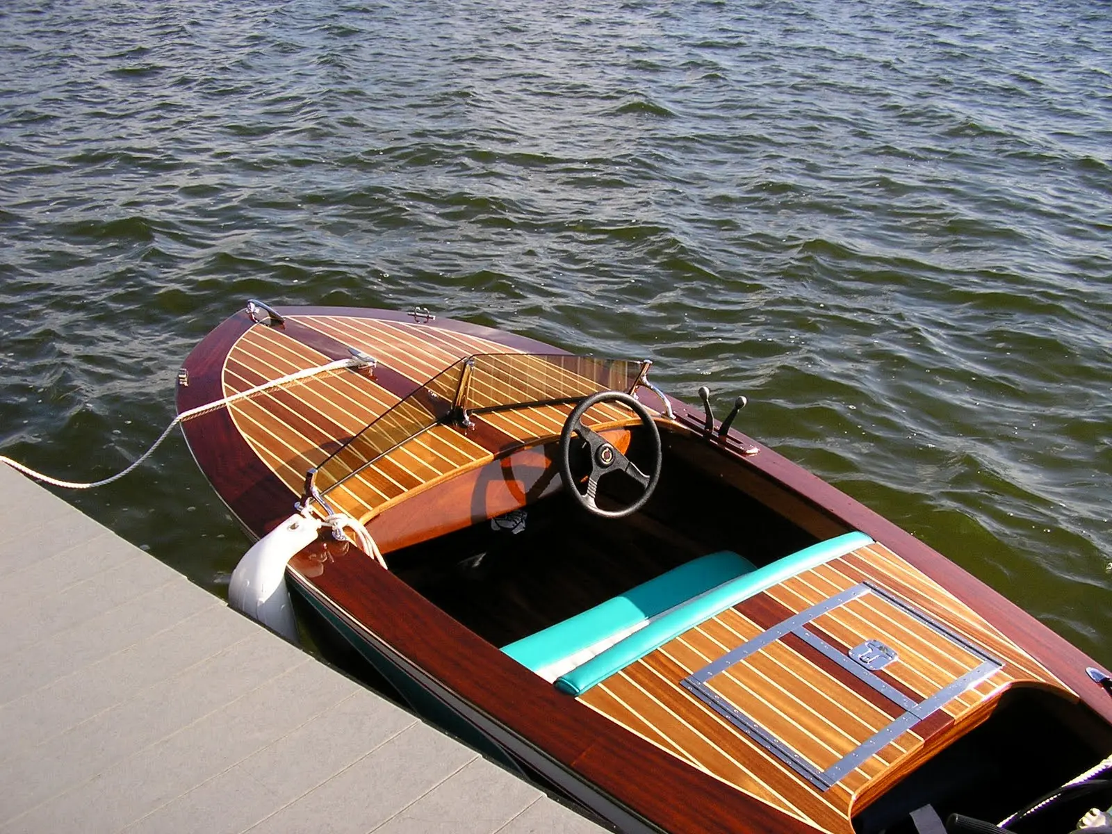
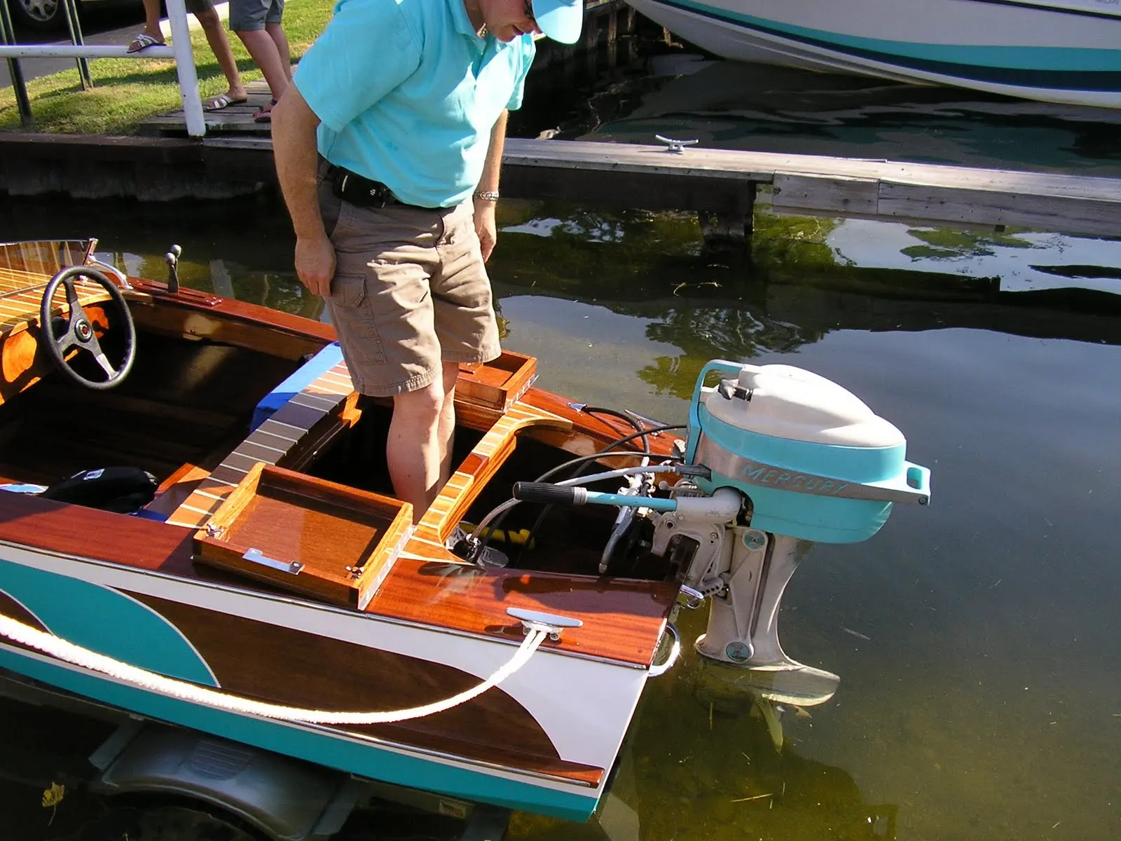
What bothers me about the lid opening backwards is access to the engine. I have chosen (because of weight) an engine without power tilt, so I have to be able to tilt it by hand. The lid might be a serious obstacle. What kind of locker it will be will be decided once the engine is on the transom. Look at the photographs below for two different lockers and the access to the stern, from their owners.

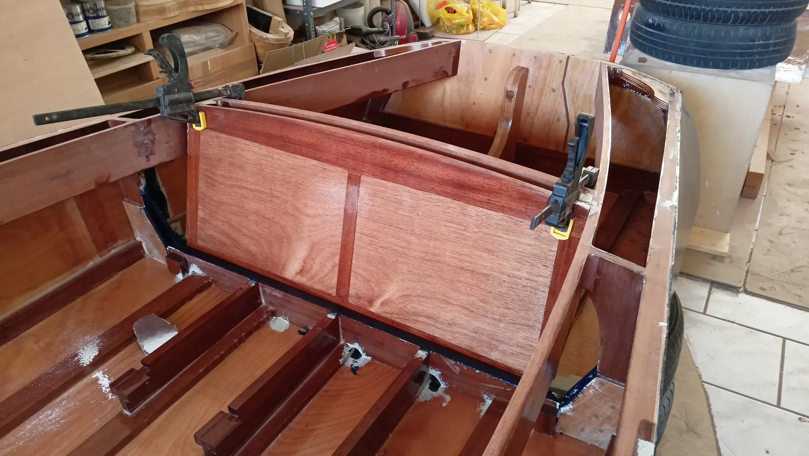
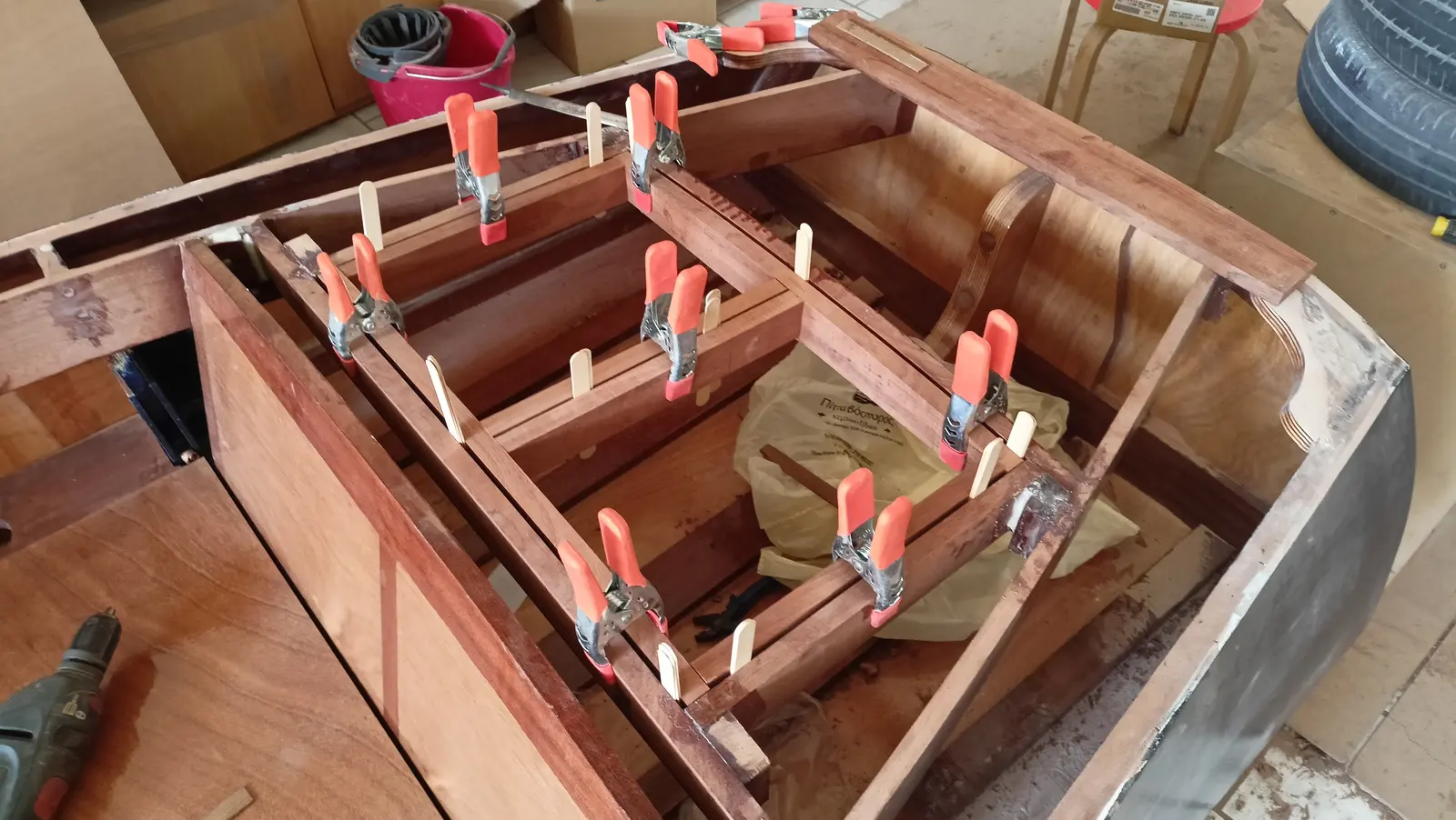
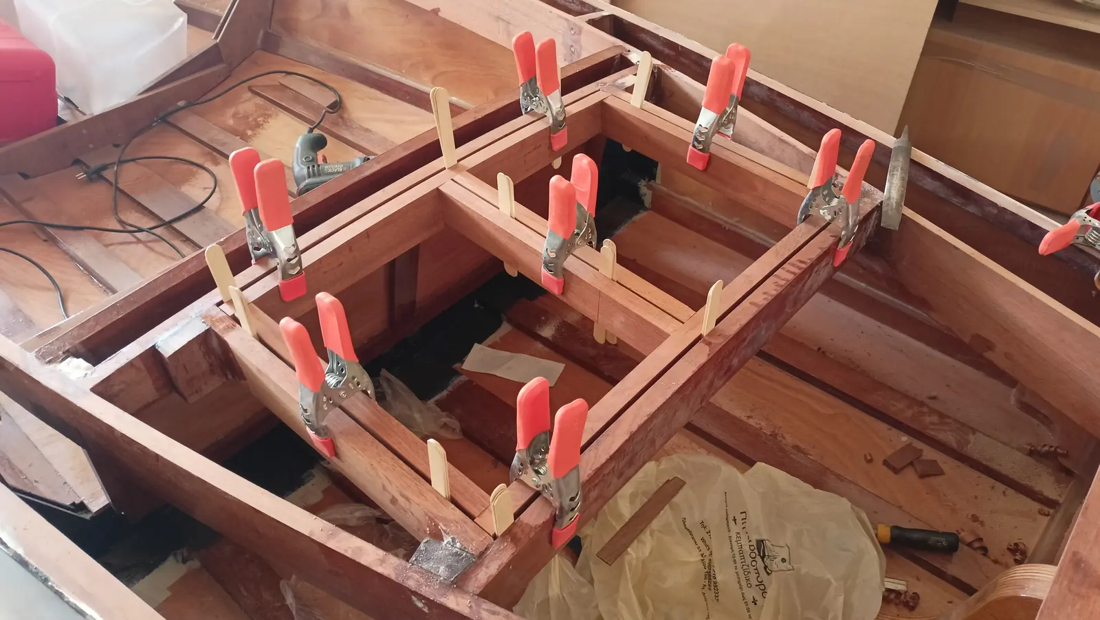
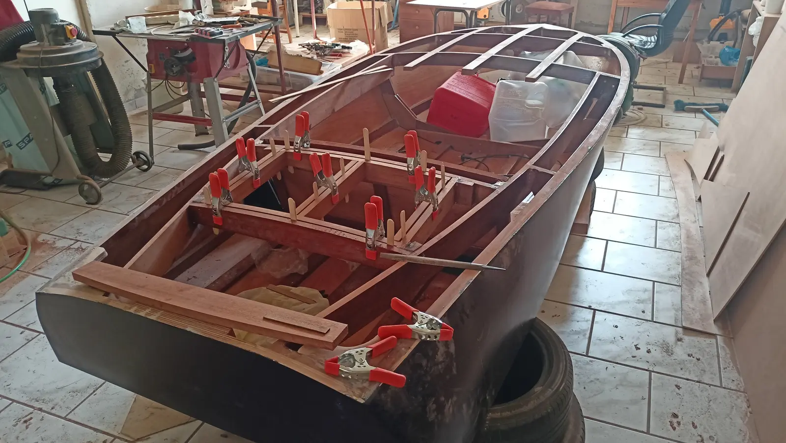
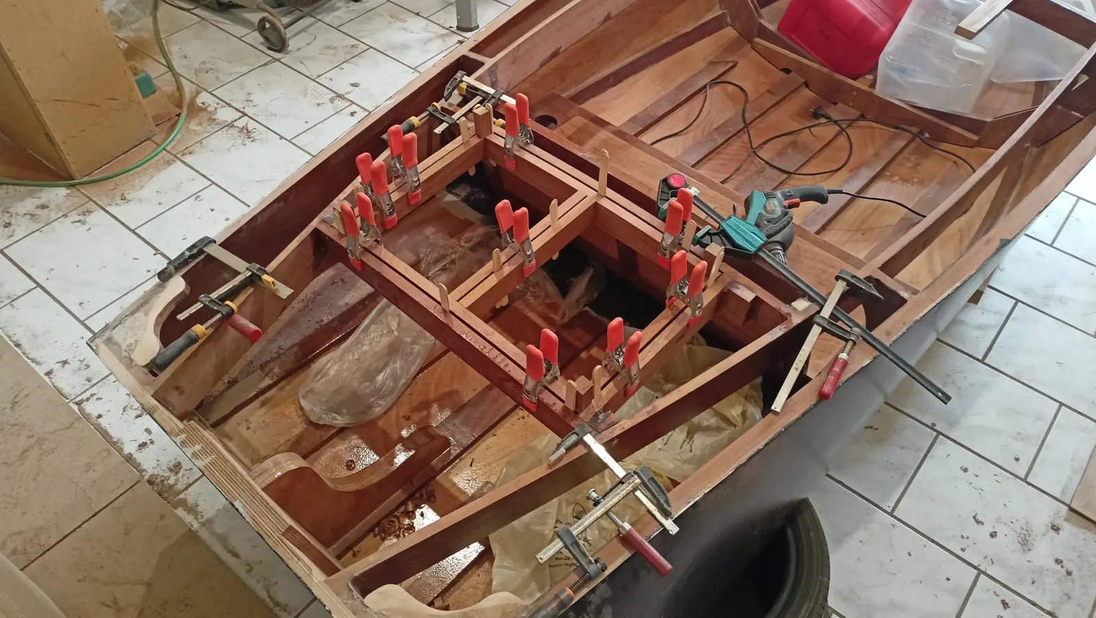
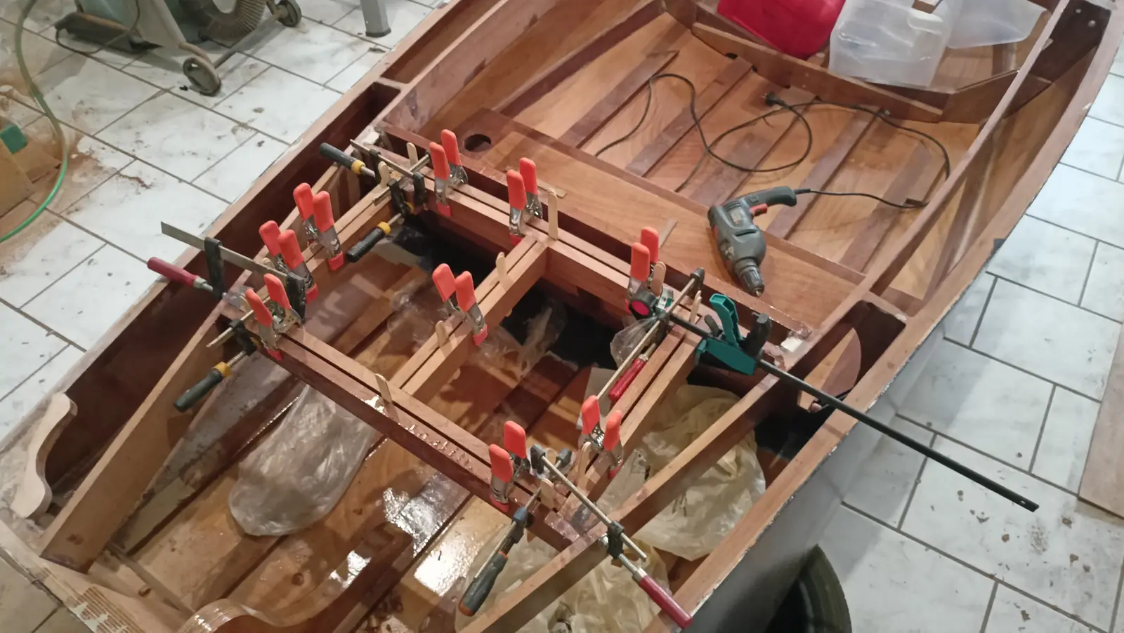
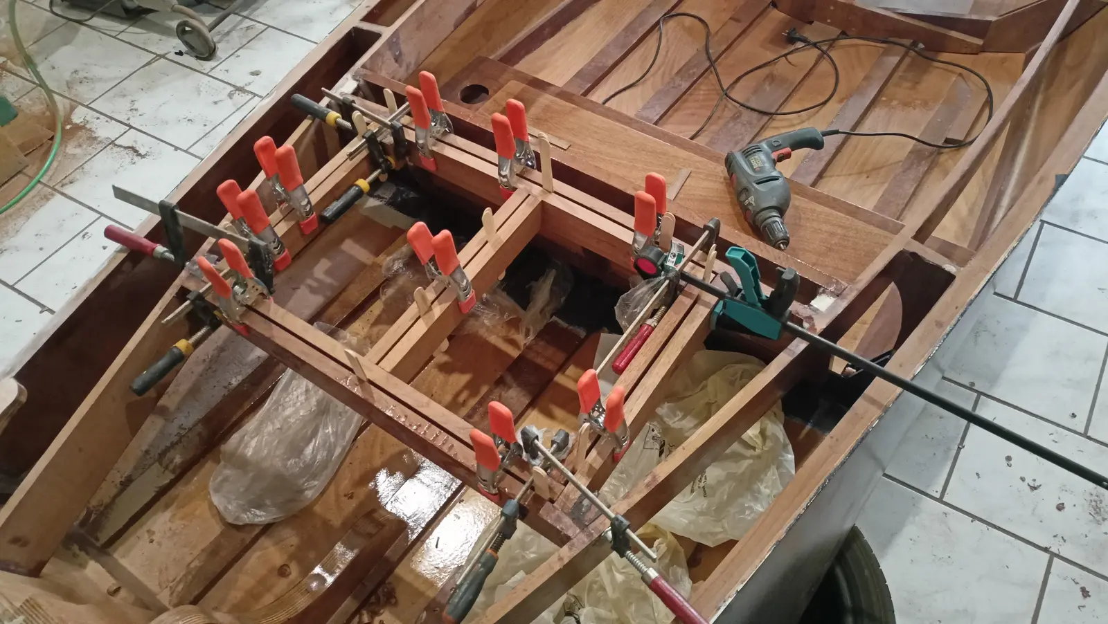
The uprights were glued in too, so we now have the rectangle the locker lid will sit in.

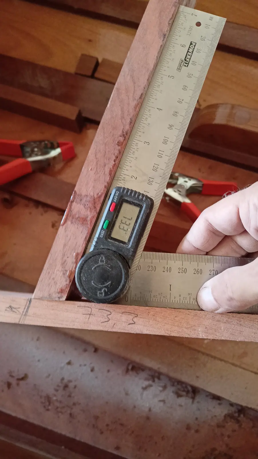
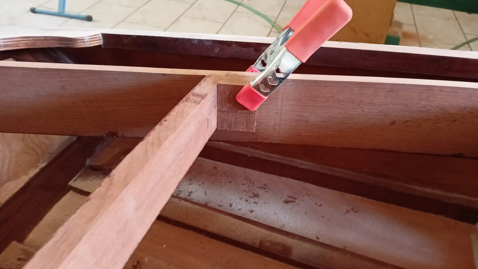
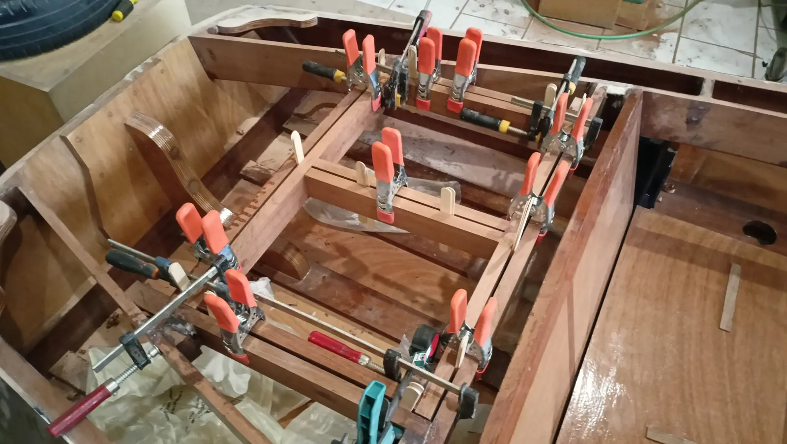
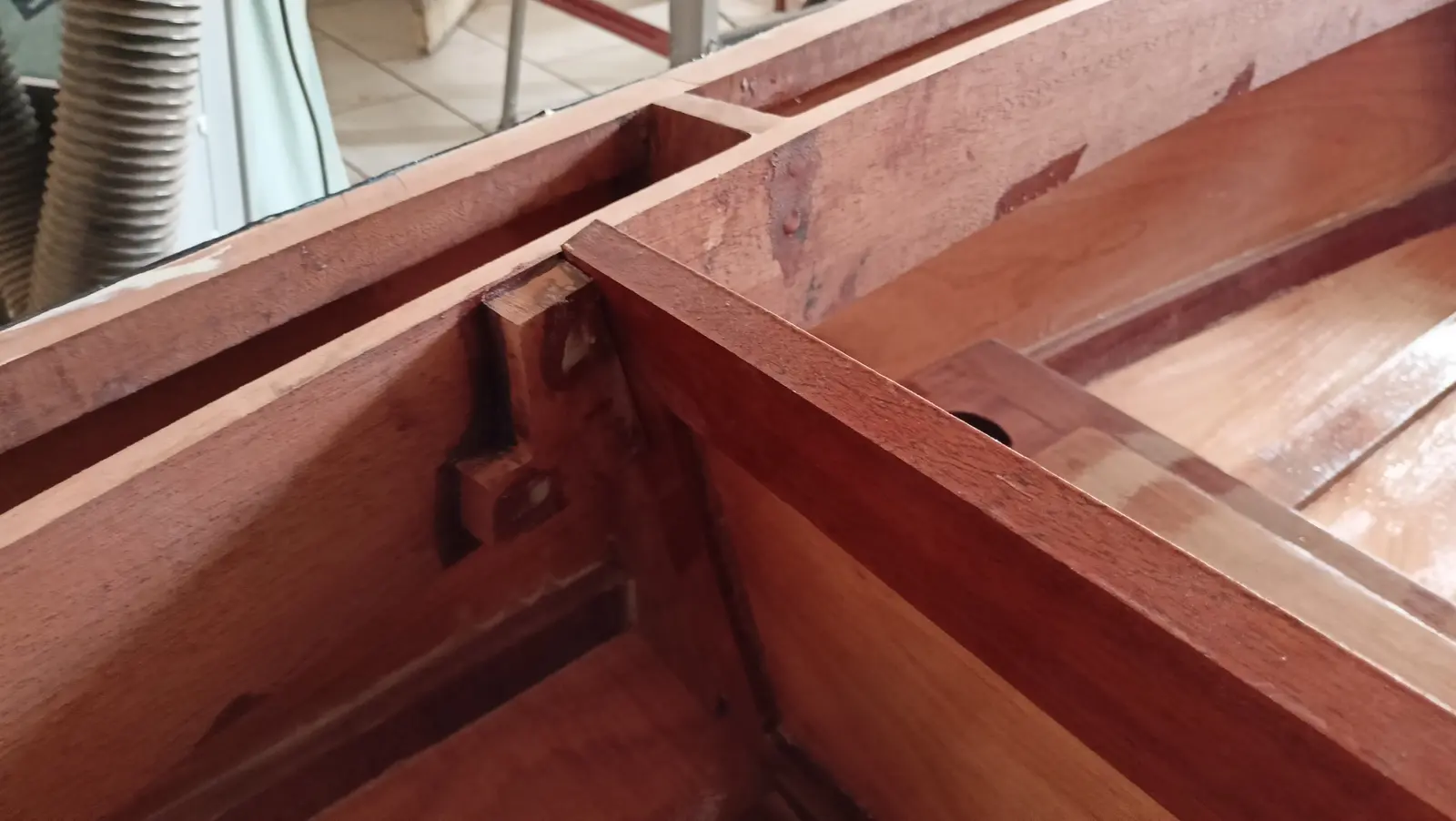
The four pieces that make up the rectangle have a peculiarity. While all four are square to the floor, the two athwartships pieces (forward and aft) are not at the same height. So the two fore-and-aft pieces were not cut square at their ends. That creates the problem that for the lid to fit the opening perfectly it will have to be made to match.

The pieces were cut at the right angle (about 85 degrees) after endless trial fitting.

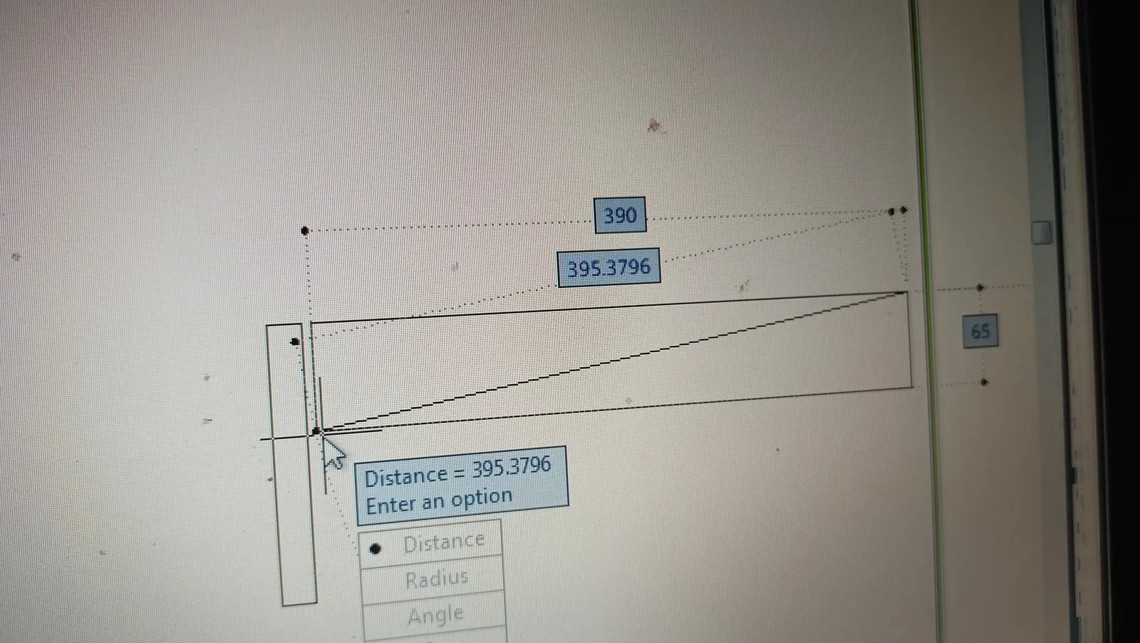
As can be seen in the photographs, I have left a gap all the way round. It is about 4.5 millimetres. I do need to check the lid will open though. So I drew a little sketch in AutoCAD simulating the lid. I can see that the diameter of the circle centred on the hinge, with the bottom of the lid as its radius, is 1.36 millimetres more than the gap I have left. A very small problem, I will take a little off the bottom of the lid and it will open. I do not want to leave a bigger gap because it would look bad. See the photograph below and the video at the link, which explains how I check whether the lid will open or not.

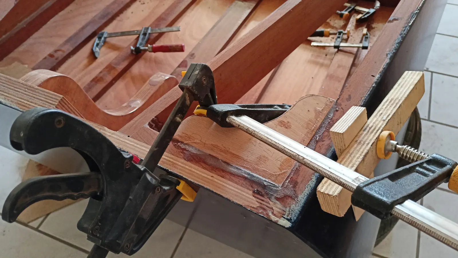
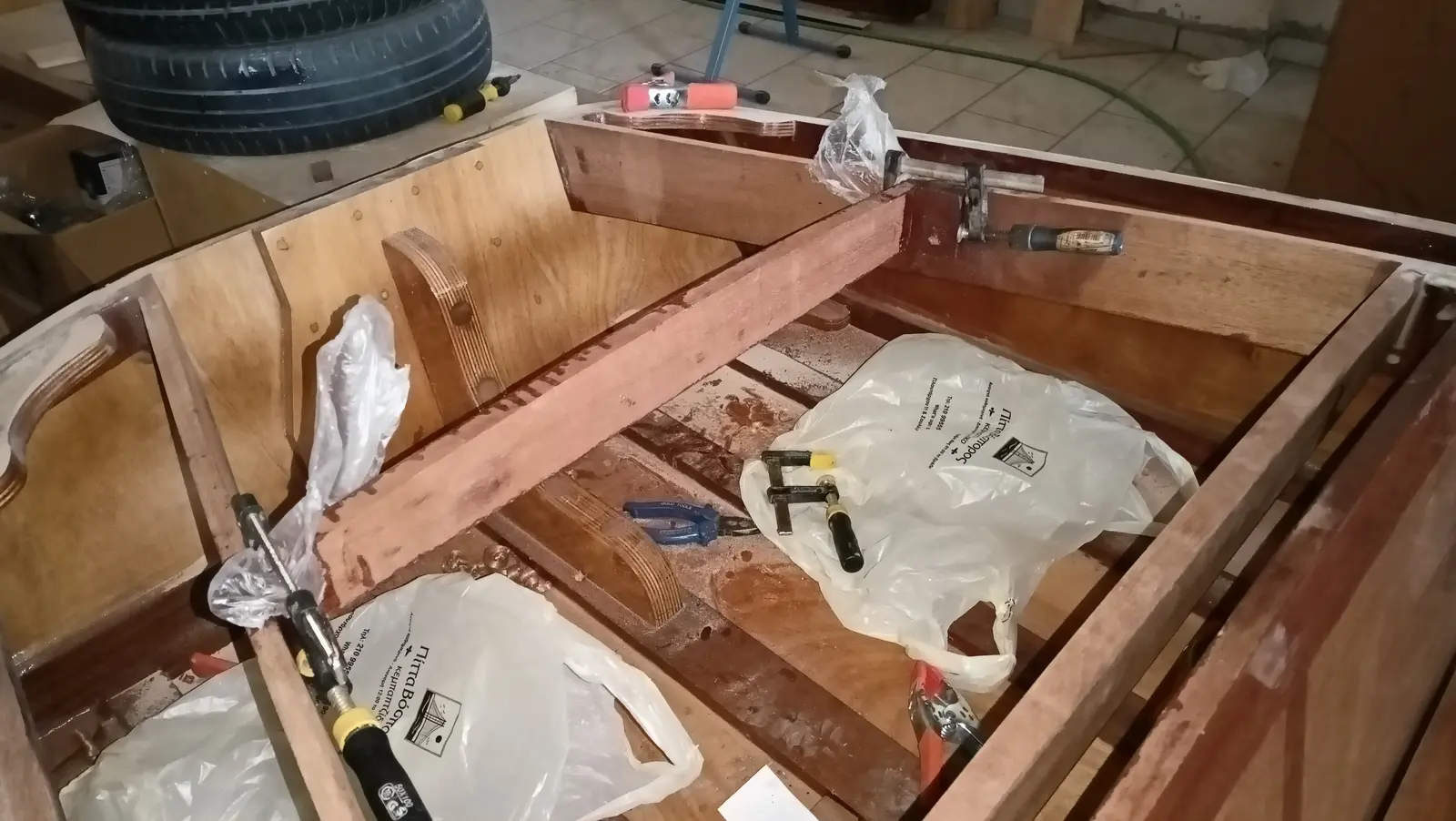
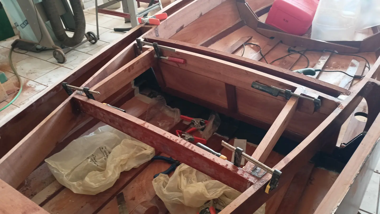
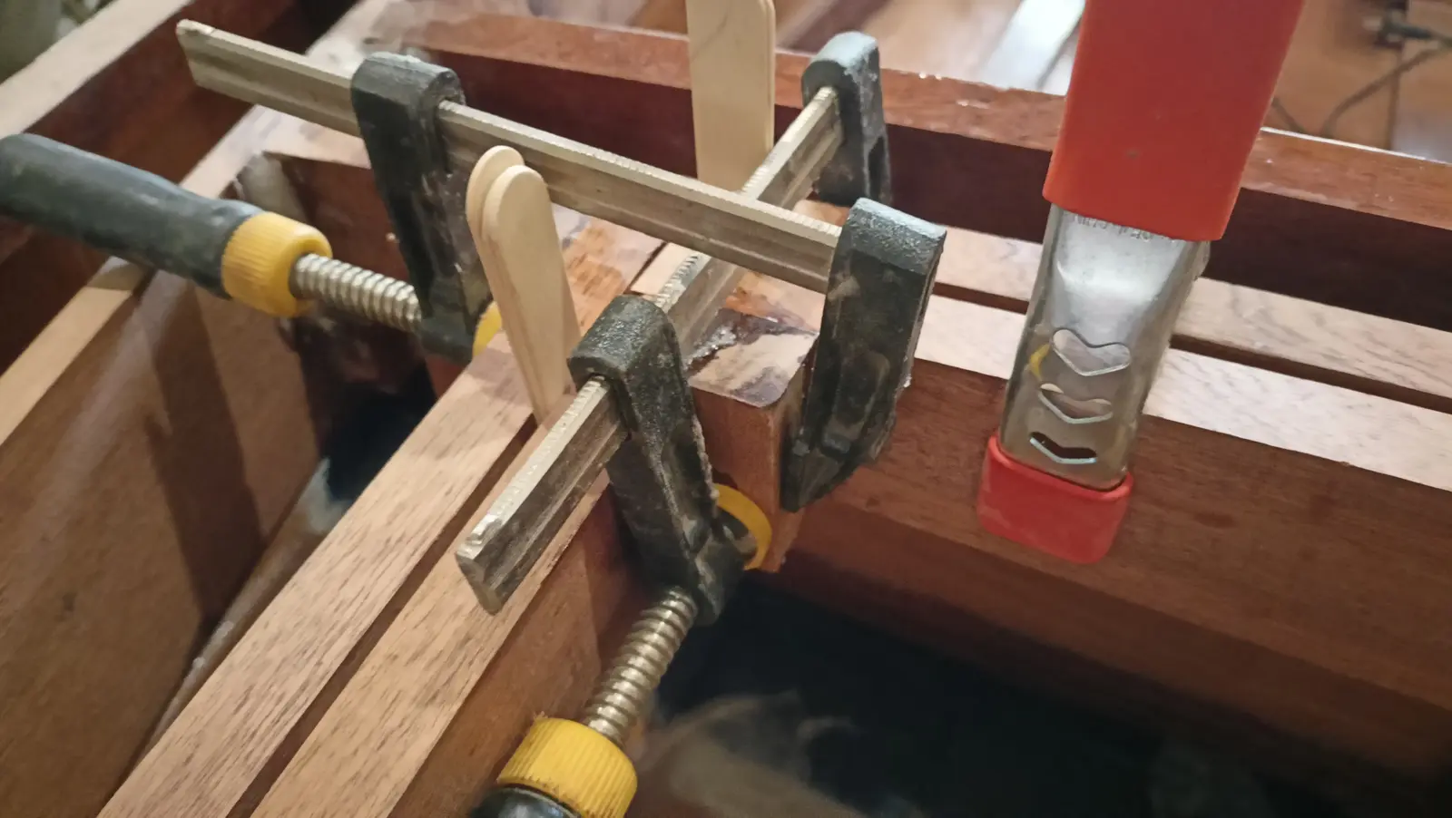
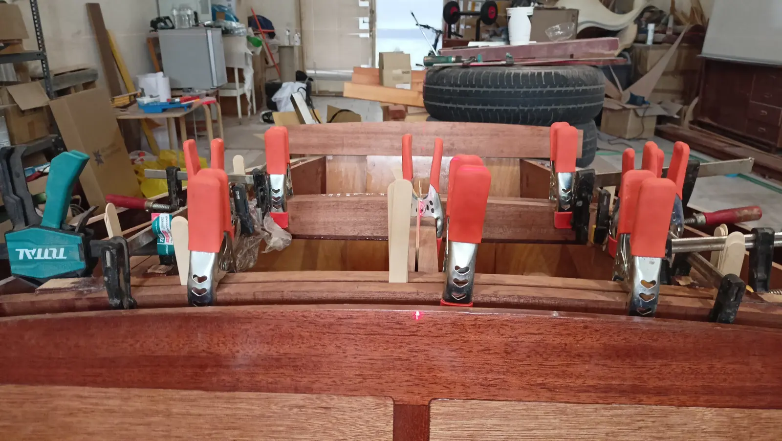
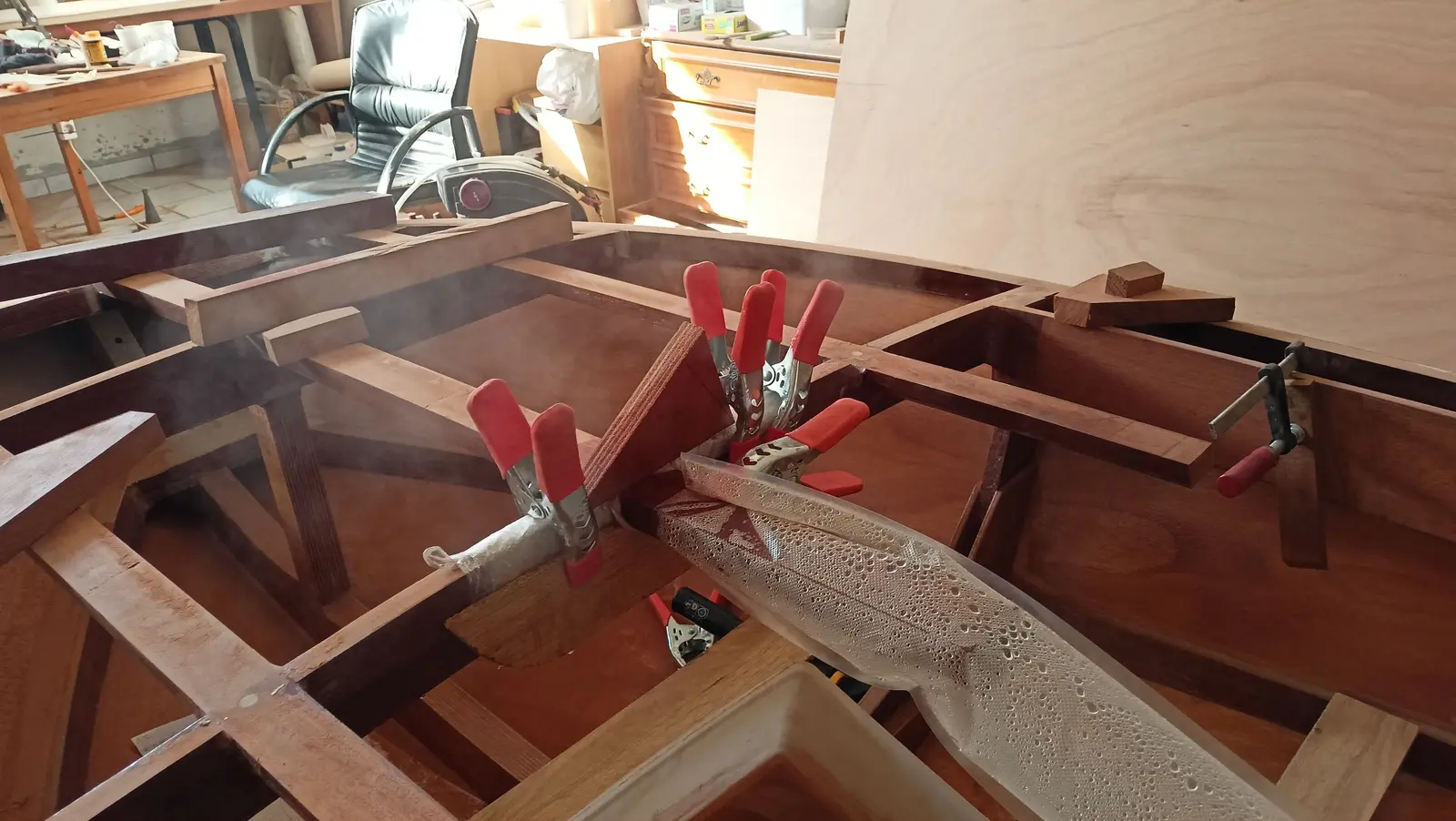
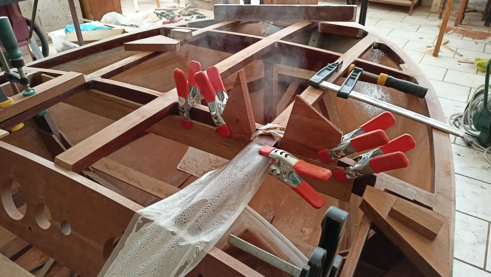
The lid has to match the forward and aft pieces perfectly in height, as they have been cut to the same curve (the aft piece has not been glued yet). That is because the plywood will then be glued over the top and it has to bed down perfectly everywhere. For that reason I decided to clamp the lid up with absolute accuracy, exactly as it is at the moment, unglued, and glue blocks into the corners. That way no piece can move at all and I keep its geometry correct. Having tested that I could get clamps on it, I went ahead and glued the four outer blocks.

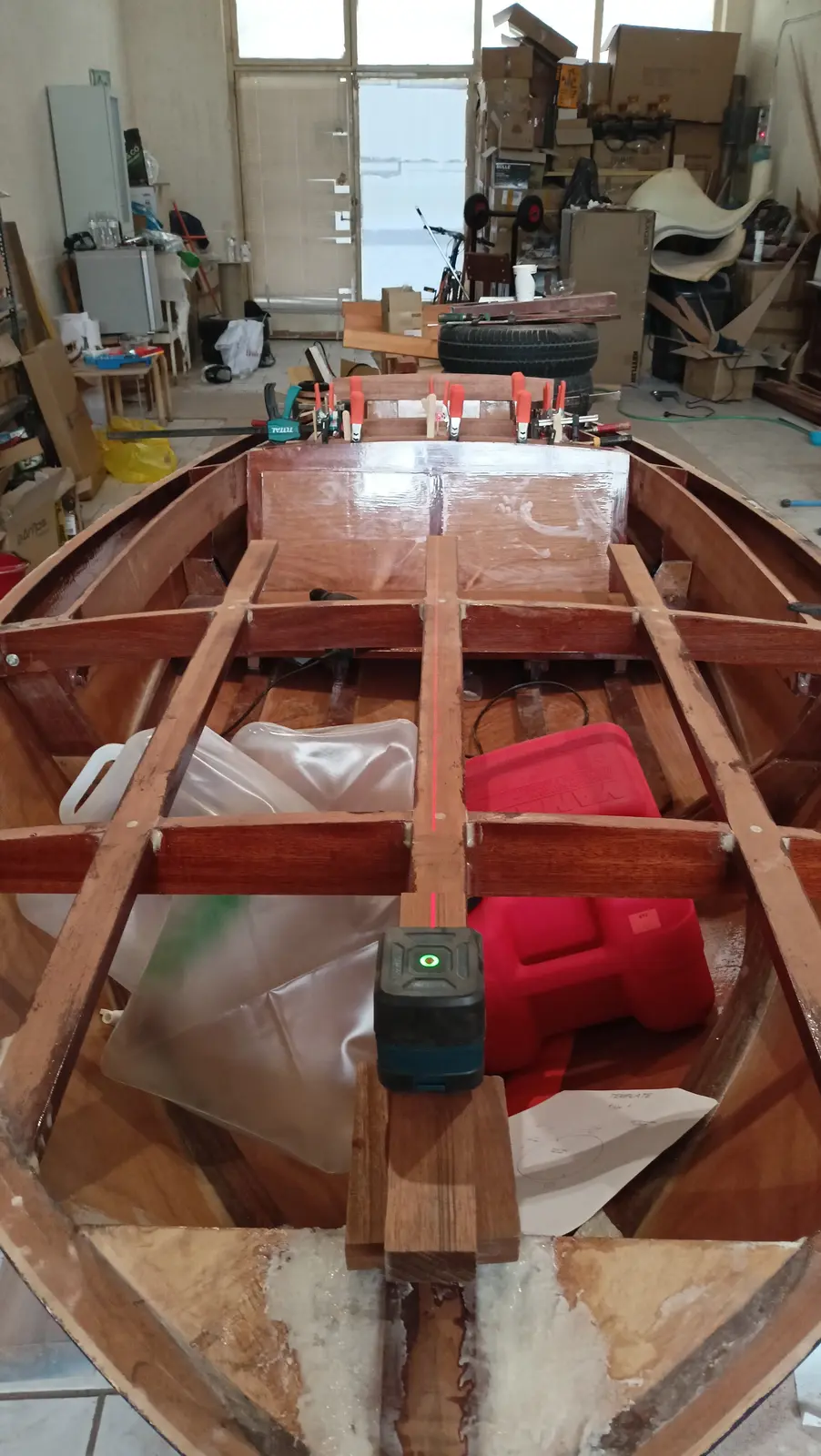
To glue the two inner pieces I need to find the boat's centreline. It was found with a tape measure, and confirmed with the laser.

However, I decided I should not glue the two inner pieces because how the locker opens matters. Depending on how it opens it will have a different hinge and therefore a different arrangement of the pieces it bears on. So those will be glued later. The last piece aft of the locker will also be glued later, because I am thinking all the cables running to the engine will probably come out there. So I want to test how much of a gap is needed between the two pieces, so they can turn and fit between them. (The locker work continues in Interior work No. 4.)

Link

Buying the outboard

Choosing the outboard was a very nerve-racking process, with an awful lot of hours of reading. On one hand the company that designed the boat in 1956 recommends an outboard of up to 9.9 hp, on the other a lot of people who have built it have fitted considerably more. Most have gone for 20 or 25 hp, two-strokes, to keep the weight on the transom down.

After looking hard for a used two-stroke without success, I decided to buy new. To my great surprise I found that the new Suzuki, Mercury and Tohatsu engines are now very light. The 15 and 20 hp are essentially the same engine and their weight was around 48 kg without power tilt and 53 kg with it. I had almost settled on the Tohatsu with power tilt when my eye fell on the Yamaha 25 hp, which I had not looked at until then because the smaller Yamahas weighed a lot more than the equivalents from the other makers. As it turns out, in 2017 Yamaha replaced the previous model with a new one (the 25G), which is now a twin cylinder, dropping its weight by about 15 kg. So the short shaft with remote control and without power tilt weighs 56 kg. The weight is marginal for the size of the boat and I did not know what to do.

So I started looking for other people who had fitted outboards of a similar weight to this boat. I found two cases, one who had fitted a 20 hp Yamaha weighing 57 kg and a second who had fitted exactly the same model. So I made the decision to buy the 25 hp Yamaha.

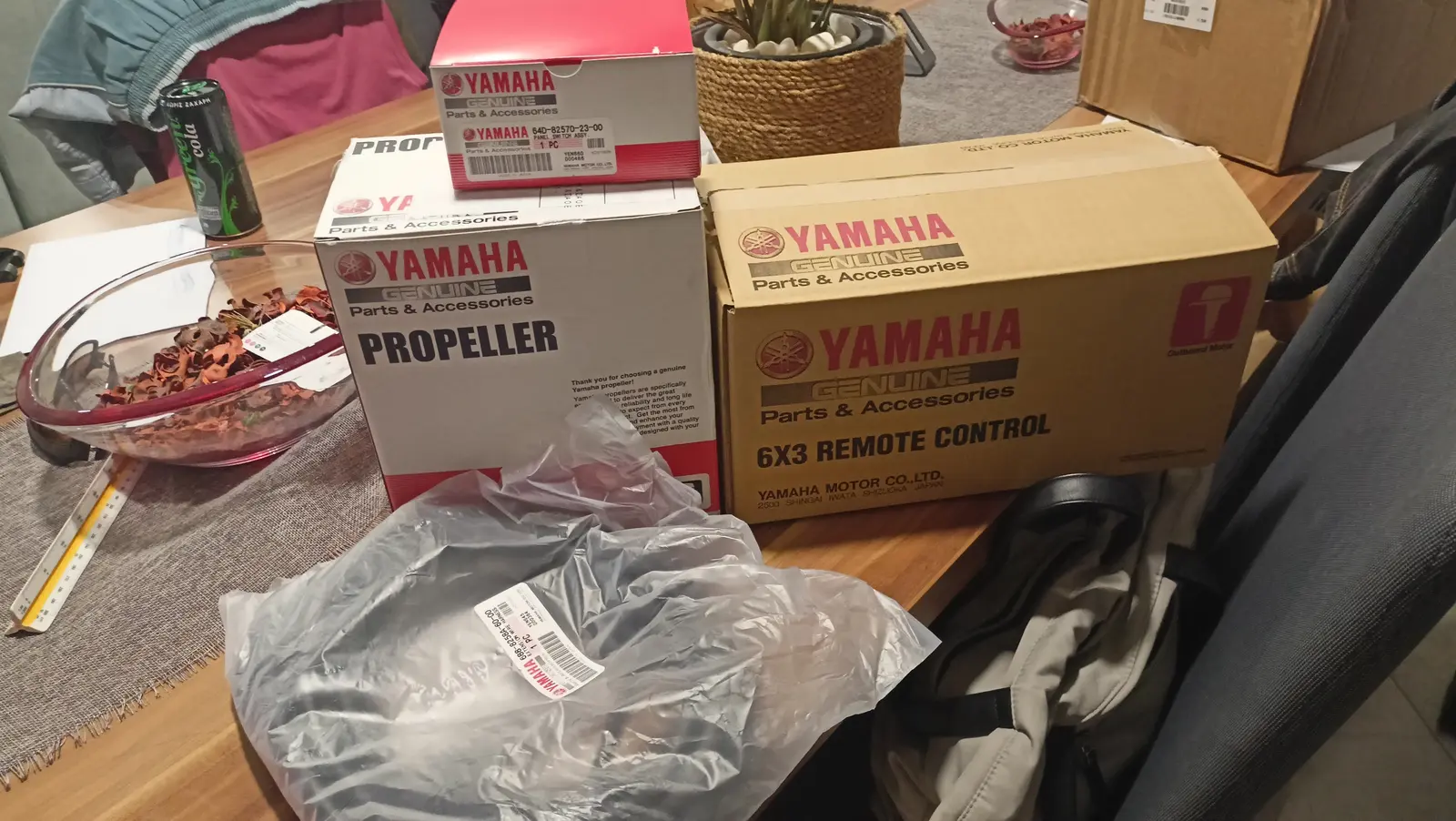
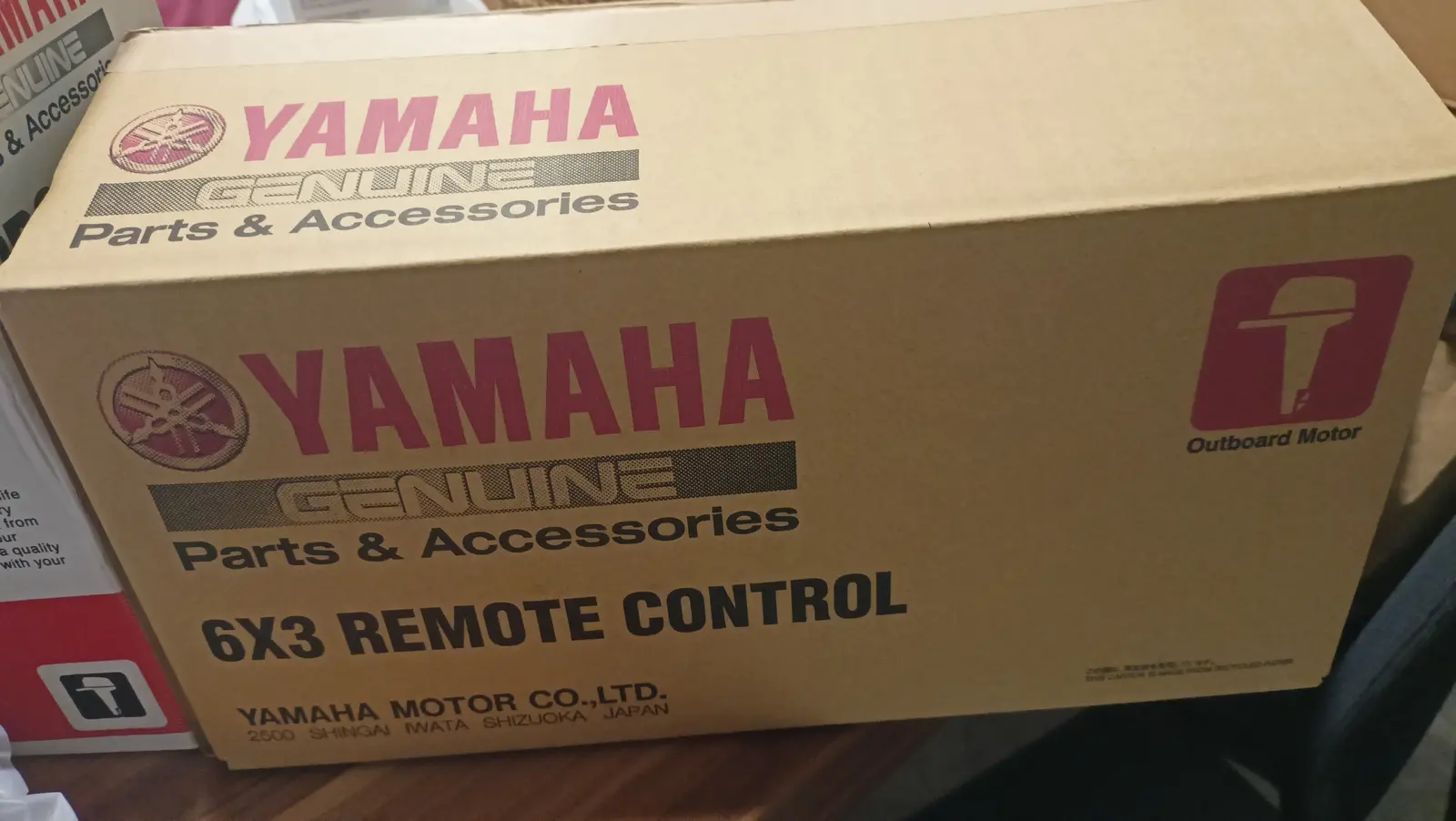
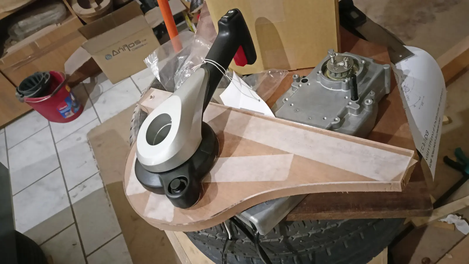
The next search was about replacing the control box with a flush-mounted one that looks better. I found that Yamaha have one that suits me, the 6X3. In fact they agreed to swap the standard control box for the flush-mount one, which of the other brands only Mercury had agreed to, on payment of the difference. Fitting this control box makes things slightly more involved, because I will have to fit the key separately. On the standard control box the key was on the box itself.

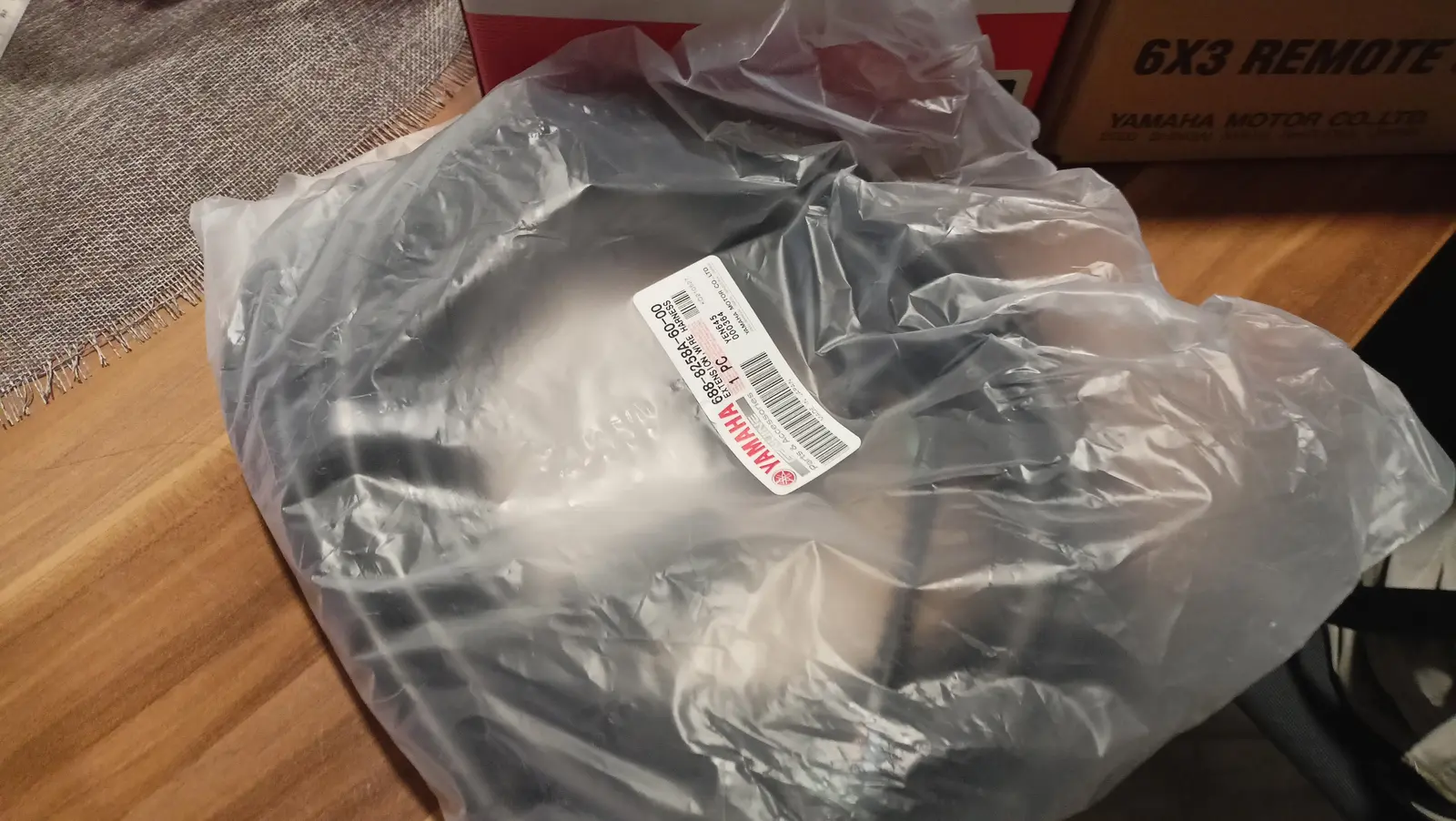
A nice surprise from Yamaha was that they include a multifunction gauge with the outboard. The gauge was not in stock, so I took delivery of everything else.

I bought it very early because I need to start thinking about installing the steering system, the dashboard with the gauge, and the size of the cutout in the aft end of the boat so the outboard can move as it should with the cables, and can tilt up without fouling the woodwork. One problem I will have to solve is how I get to the back of the boat to tilt it up. I am thinking the locker should not open backwards but to the side, so it does not get in the way.

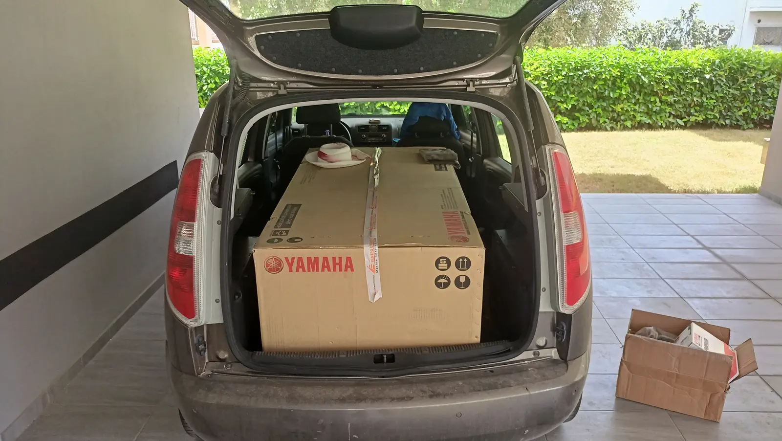
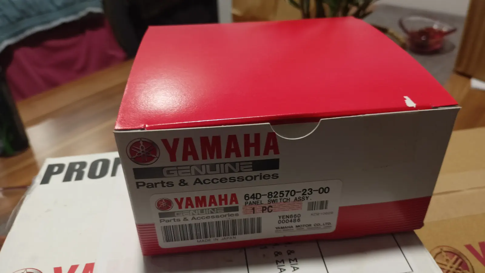
Some photographs of the outboard on the day I bought it.

The boat has been turned over again so I can carry on with the work inside. Alongside that work I will build a base for moving the outboard around easily, both with the car and inside the workshop. Something like the one below.

12.5 h Link

Building a dolly for the outboard

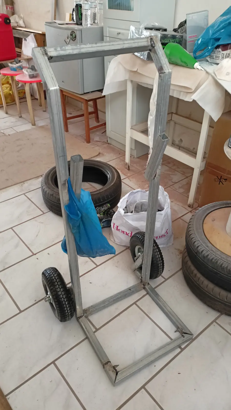
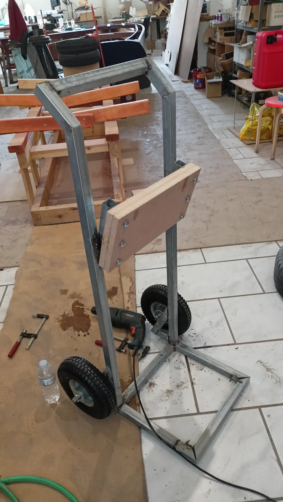
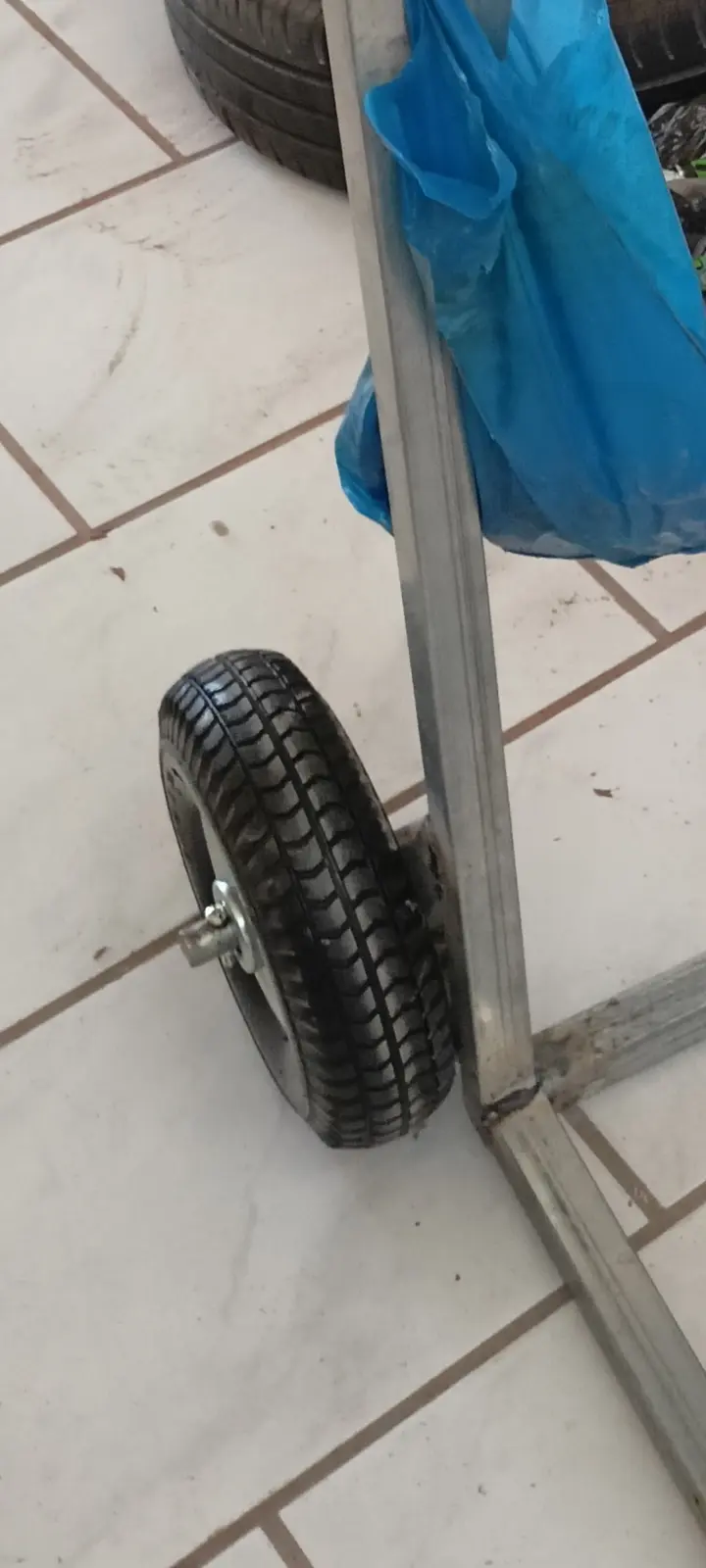
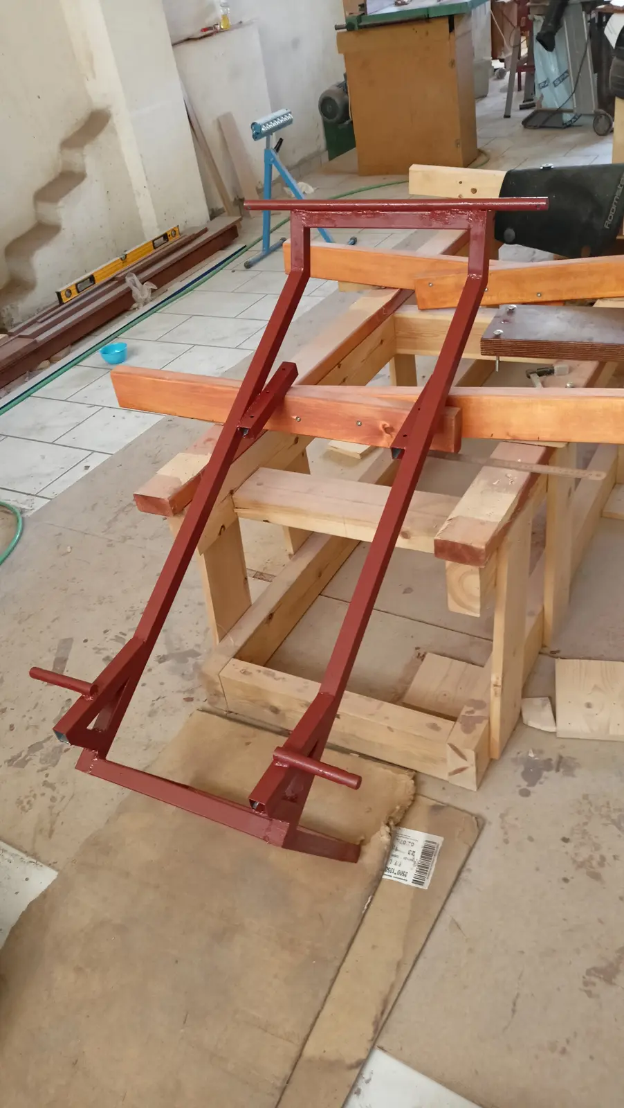
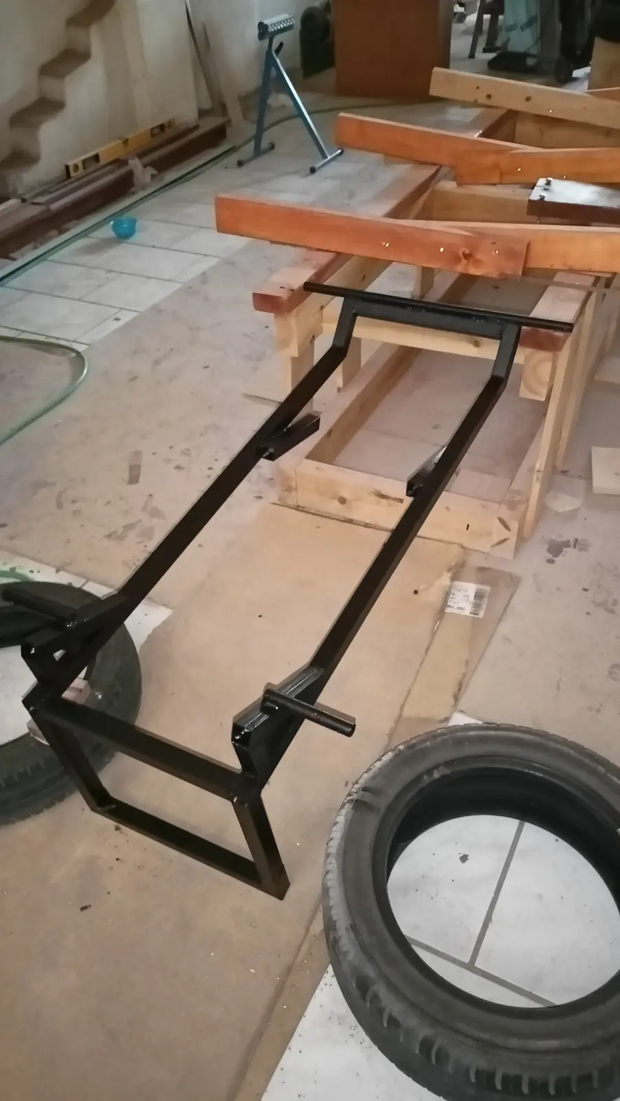
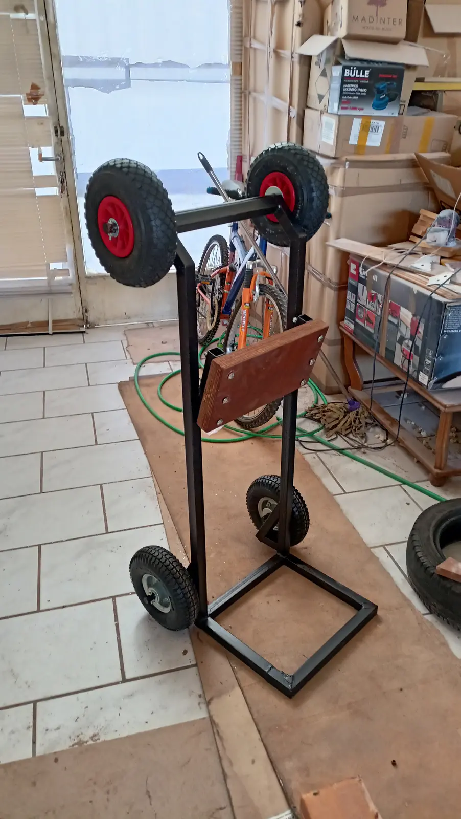
The outboard I bought (Yamaha 25 hp) is by a wide margin the lightest 25 on the market, being a twin cylinder (56 kg), but there is certainly no way a "middle-aged" man with a bad back is going to carry it about. So I decided to make a base that can go into the car very easily. The idea is to have wheels on the bottom so it can be wheeled around, and on the top so it can slide when it is laid over in the car. The base is shown in the photographs below. The wheels on the top have not been added yet, and it has not been sanded or painted.

The top wheels were fitted once the holes were drilled in the axle. It was then given a coat of rust-protective paint and after that the topcoat.
The board the engine sits on is two pieces of 2 cm plywood glued together. Four centimetres thick in total.

38.5 h Link

Designing and building the dashboard and control box

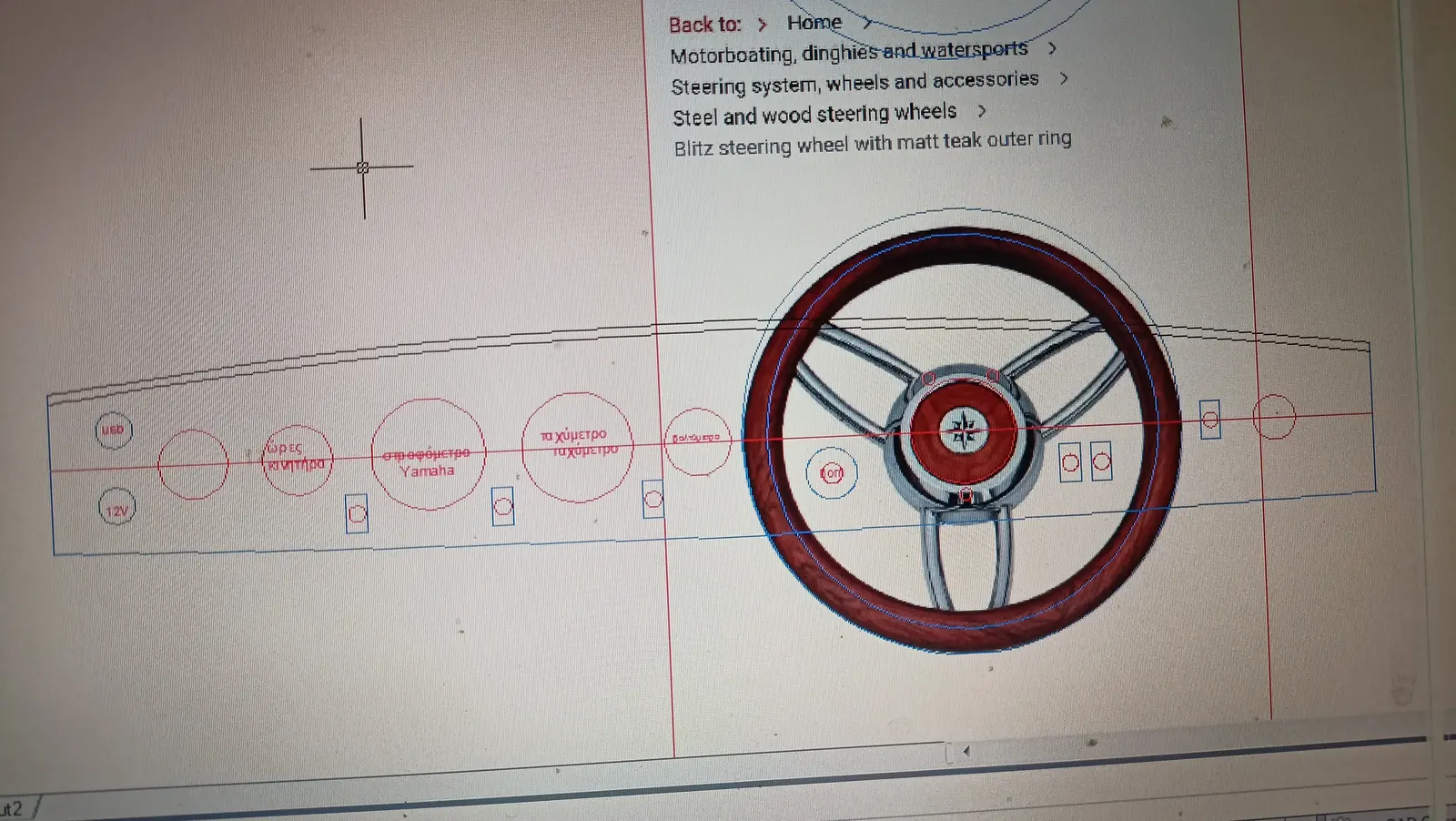
Alongside the work at the aft end of the boat, I started thinking about the shape of the dashboard, and how the instruments would be laid out.

The instruments to be fitted are:

  1. Speedometer

  2. Yamaha multifunction gauge

  3. 12 volt socket

  4. USB port

  5. Battery level

  6. Fuel level

  7. Horn

  8. Hour meter

  9. Switch for the bow lights (red and green)

  10. Switch for the all-round stern light

  11. Switch for lights in the dashboard area

  12. Switches for two pumps

  13. ON-OFF switch

I did a lot of drawings but settled on the last one.

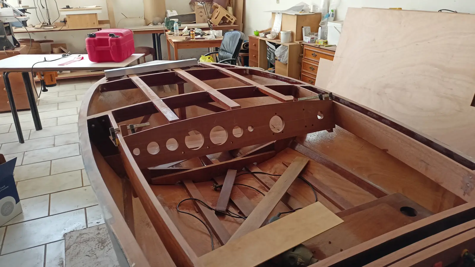
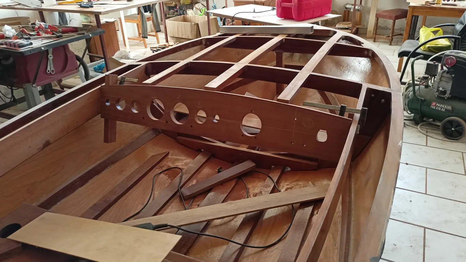
I decided the dashboard would be installed at a 20 degree angle.

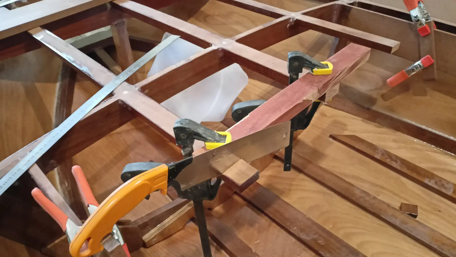
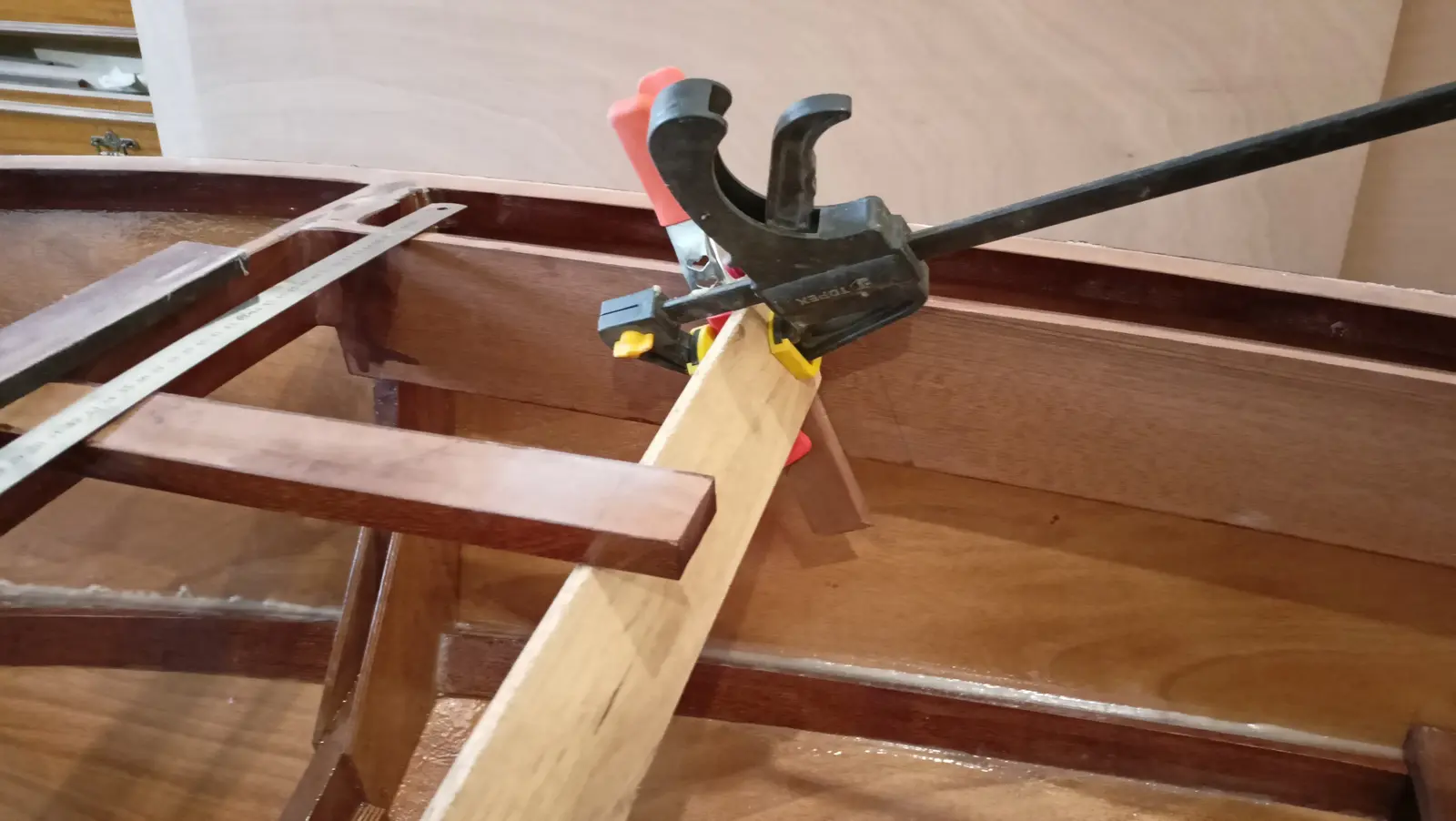
To fit it, I first cut all the fore-and-aft timbers at the forward end that land on the dashboard to the same length. Blocks were glued to the coamings at the right angle, for the ends of the dashboard to be glued to, and the fore-and-aft timbers were cut back so the dashboard would sit on them.

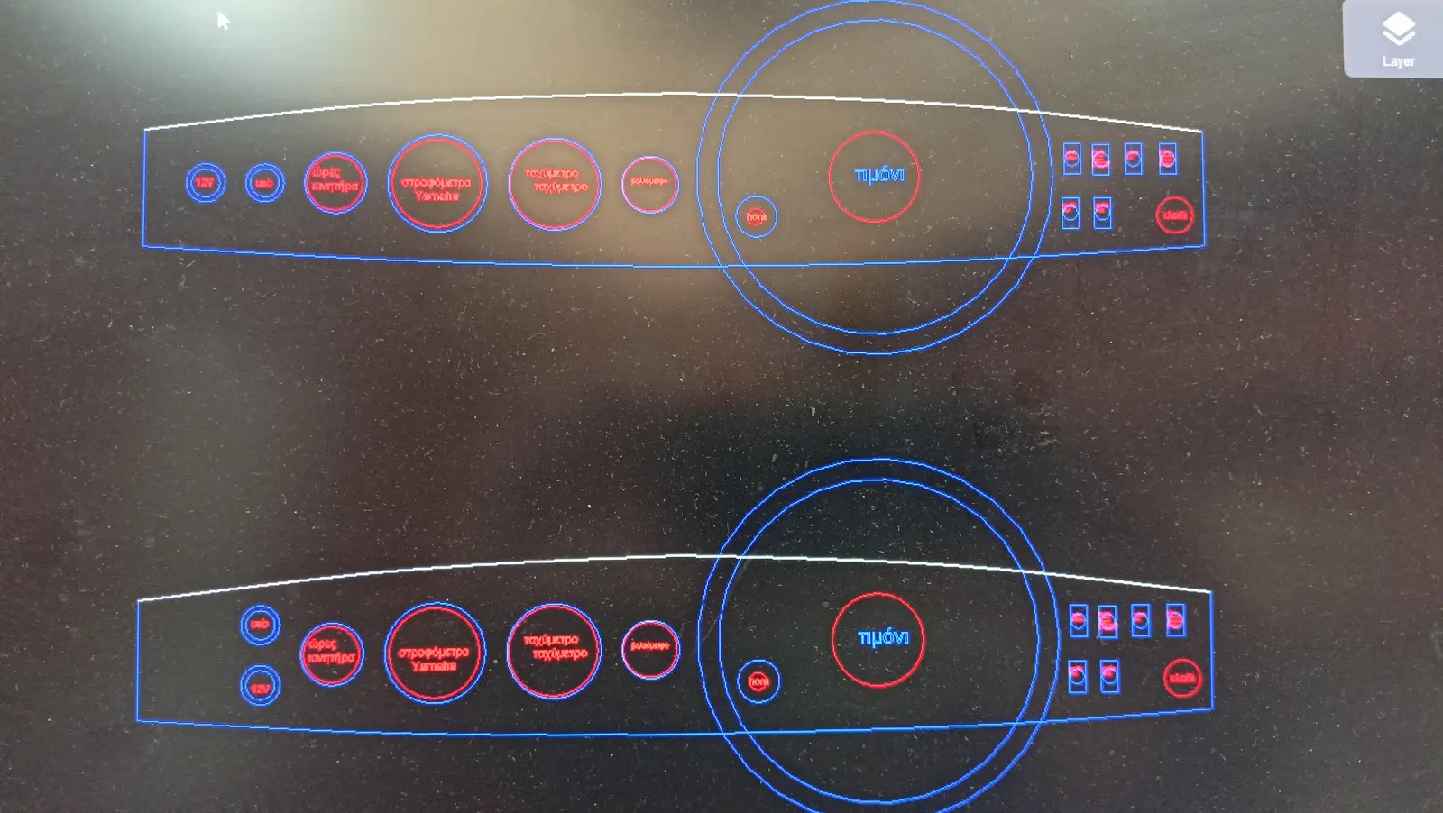
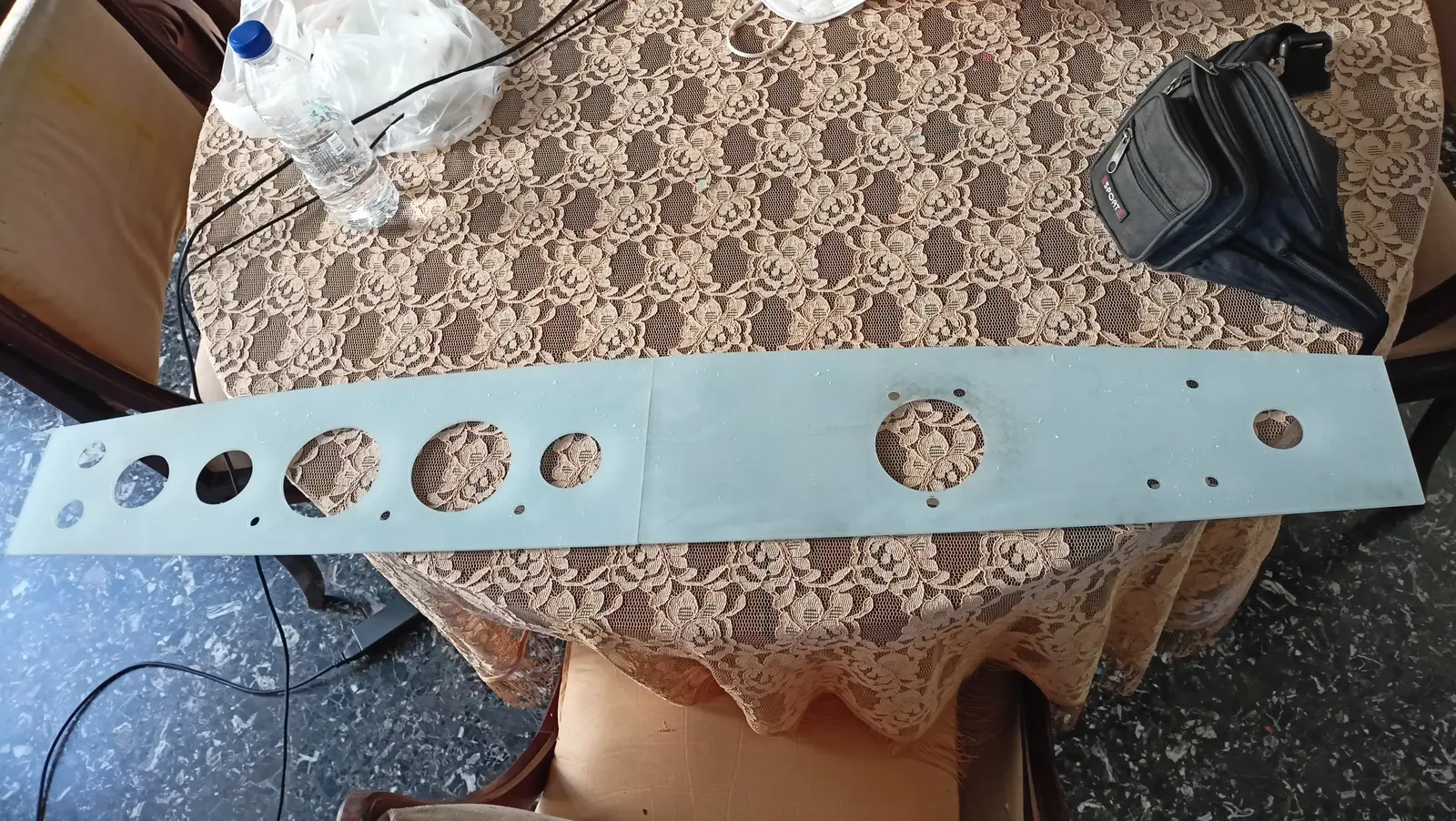
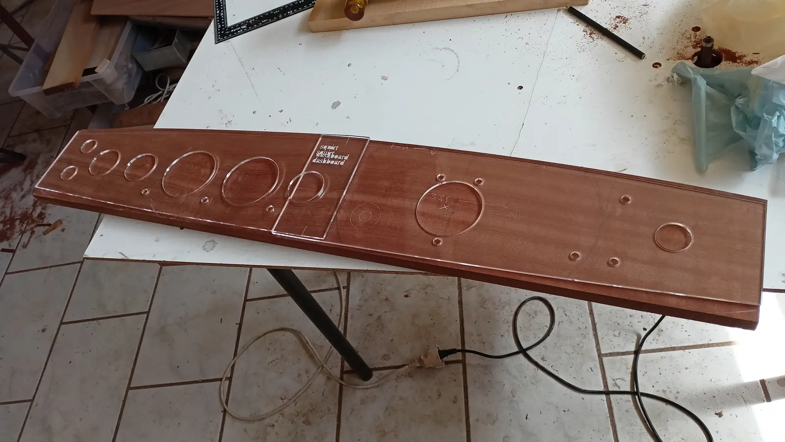
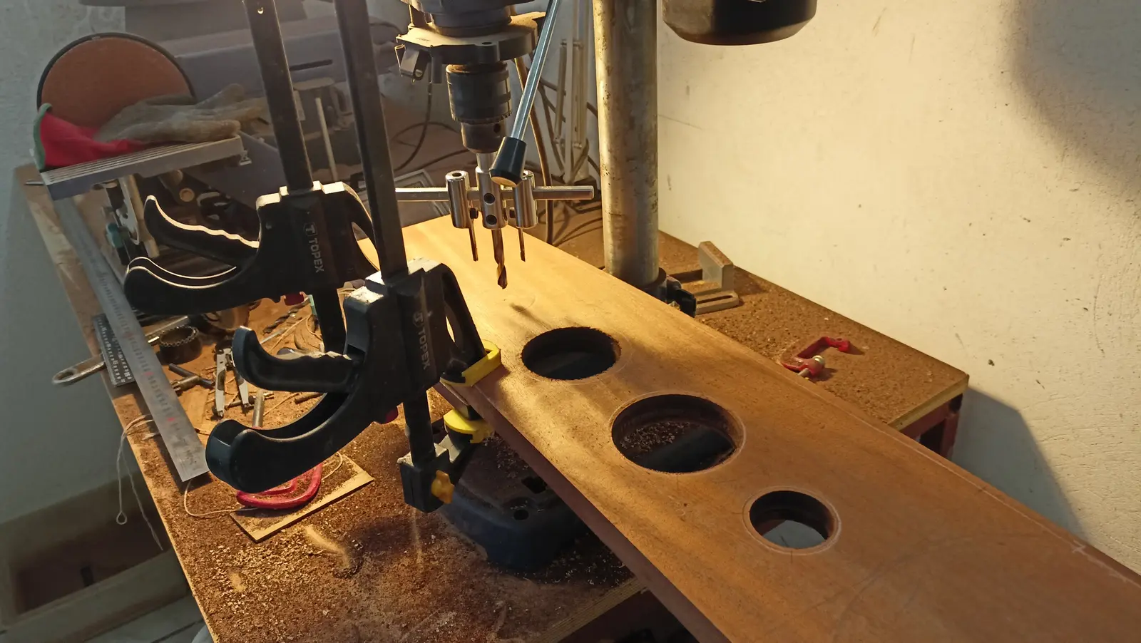
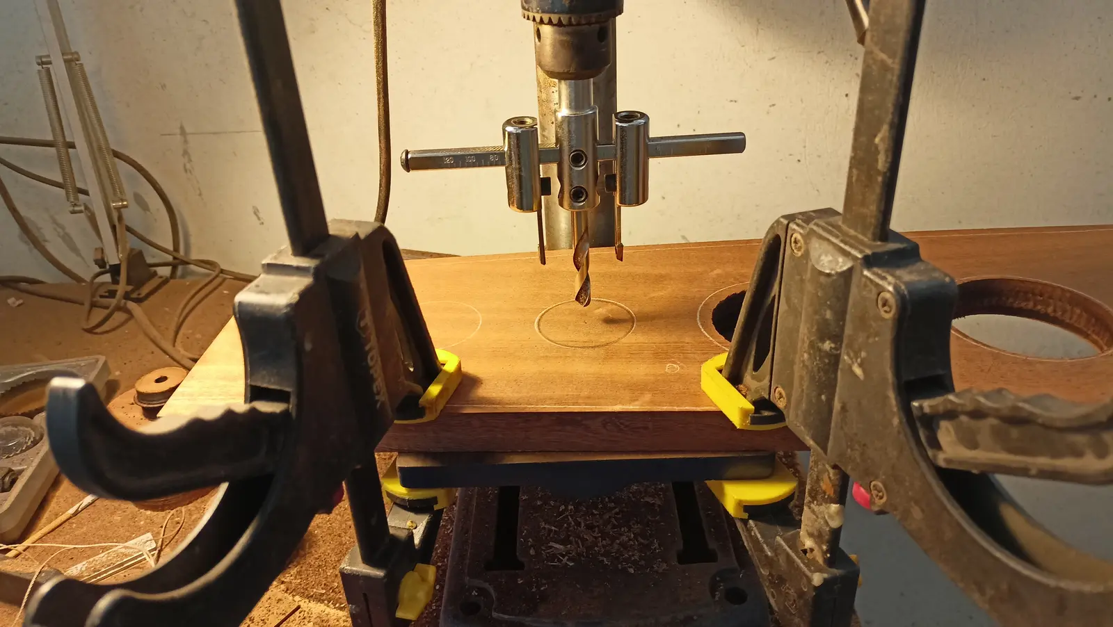
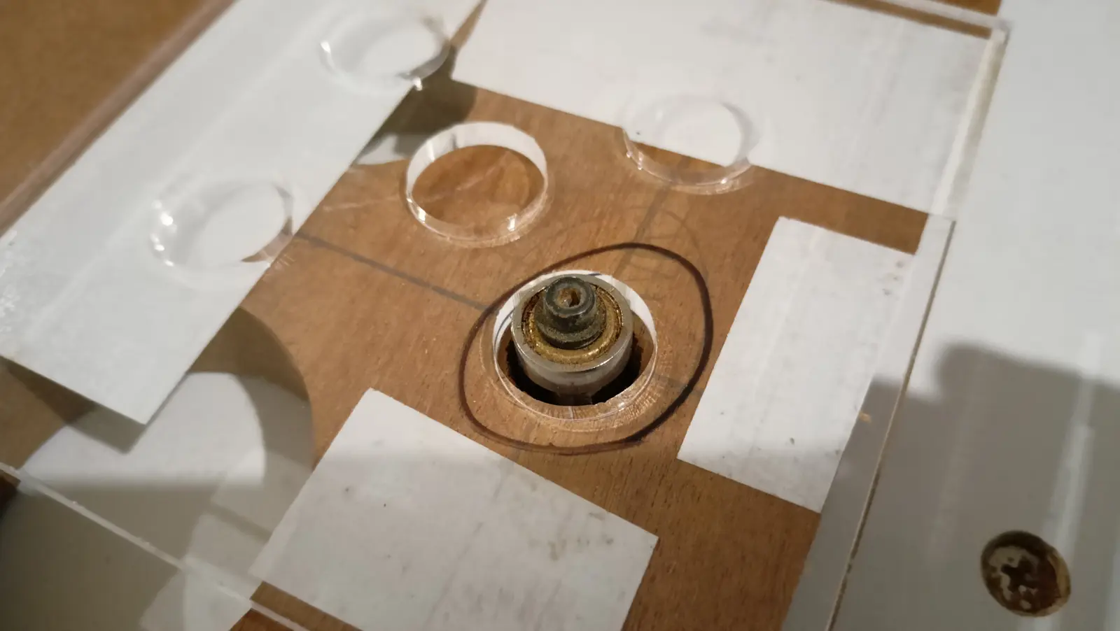
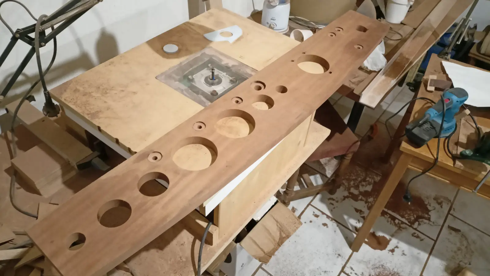
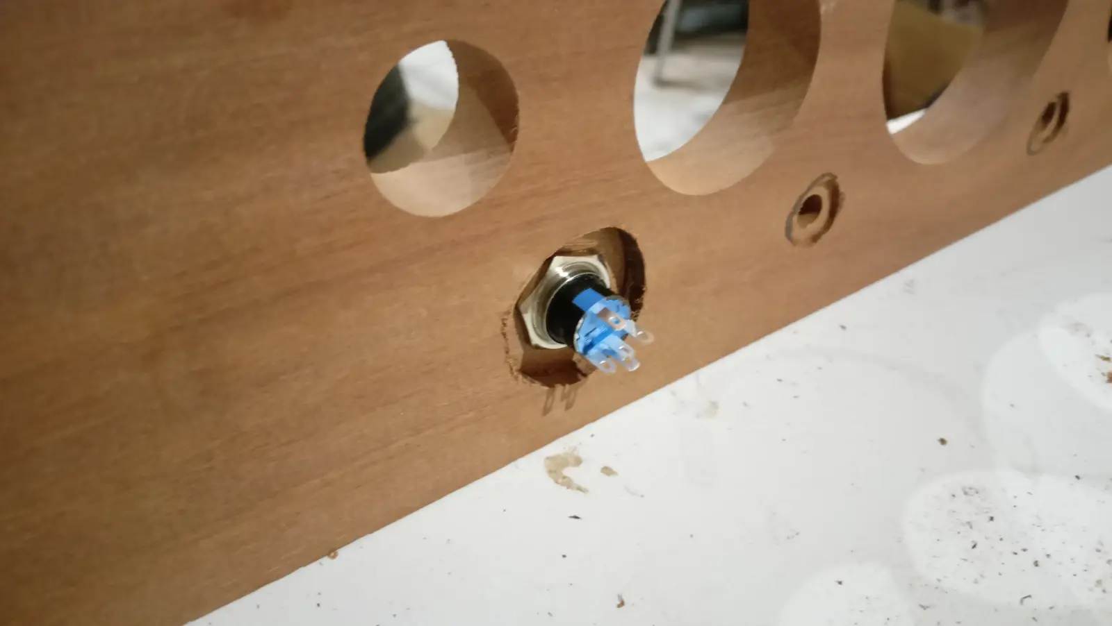
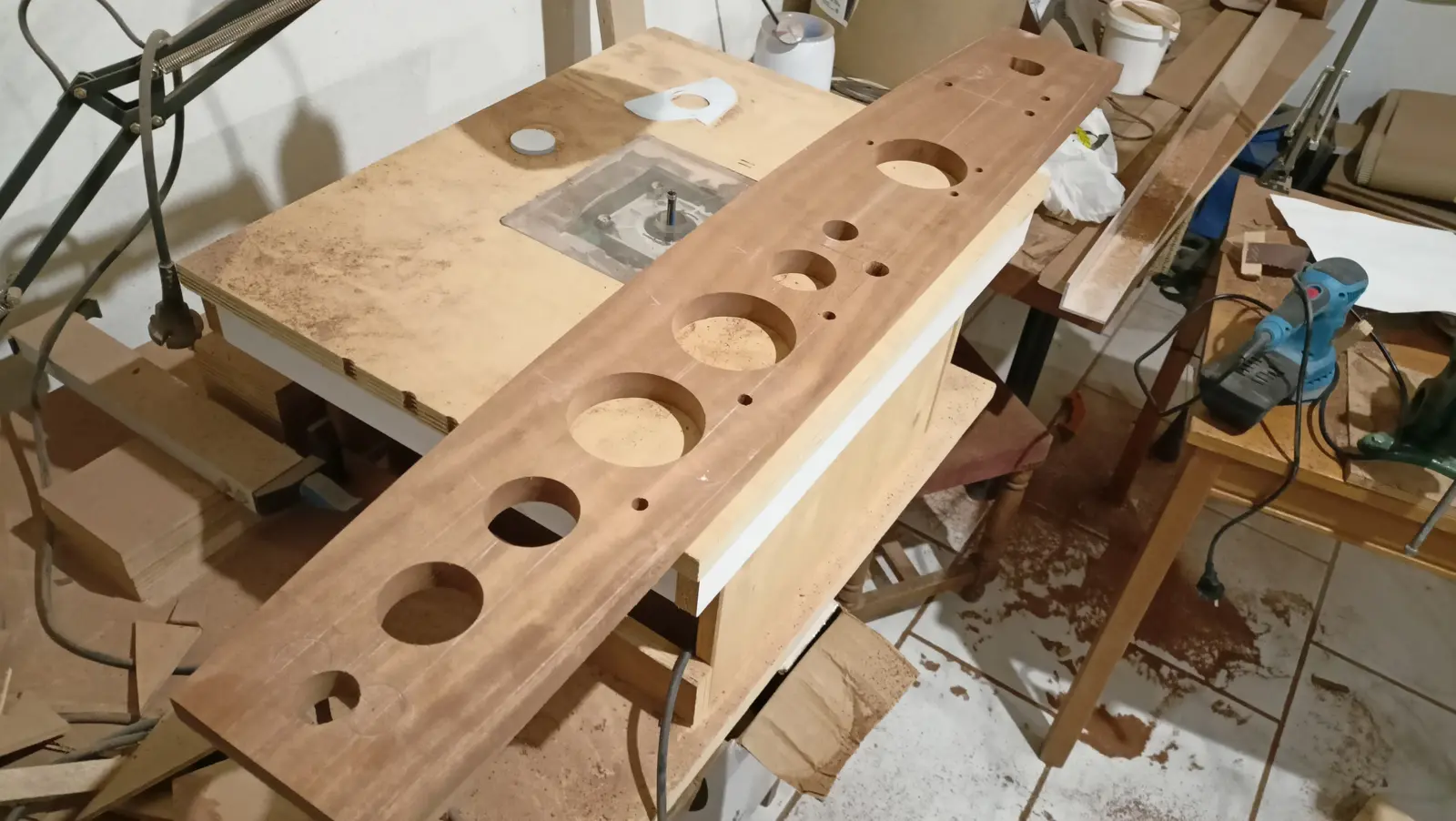
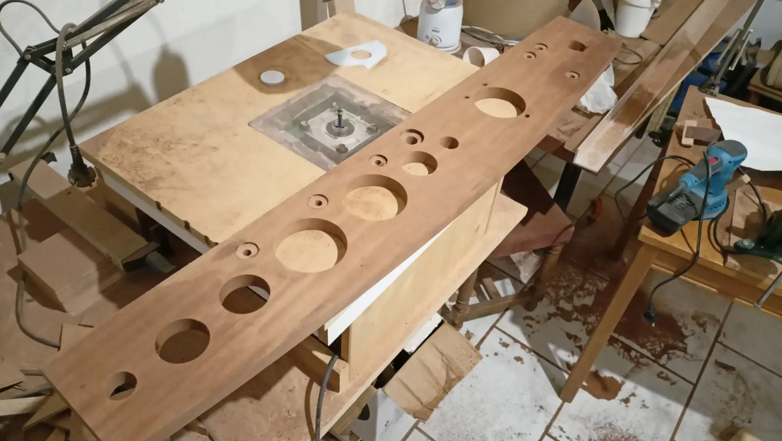
For cutting the holes, a template was laser cut so it could be finished with the router. The larger holes were cut with the tool shown in the photographs, while the smaller ones were done with a hole saw, slightly undersize. The hole saw could not manage the large ones.

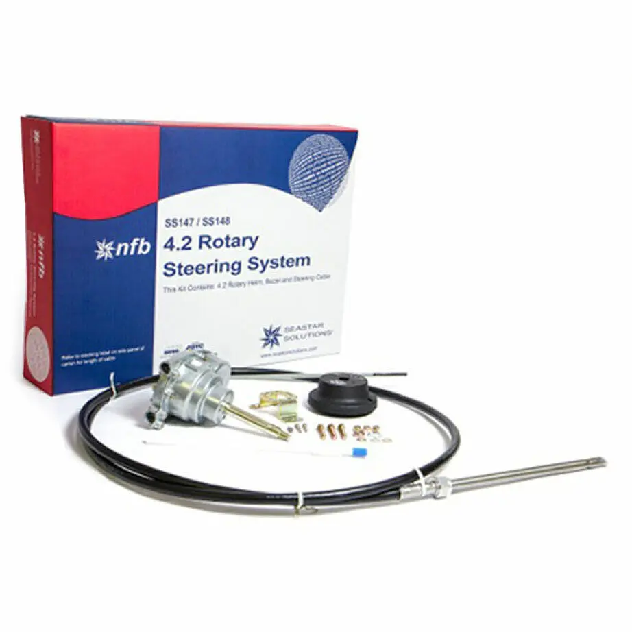
In the end I bought a mechanical steering system. It was not the higher cost of hydraulic, it was the simplicity of mechanical. I chose the SeaStar 4.2 SS147. The system is heavy duty and is used on much larger boats with engines up to 150 hp.

It was not available in Greece as a kit, but all the parts were. These are:

  • TFX N.F.B. 4.2 steering helm
  1. SeaStar SSC62 TFX Quick Connect 16 ft steering cable

  2. SeaStar TFX NFB 90 degree bezel kit

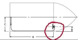
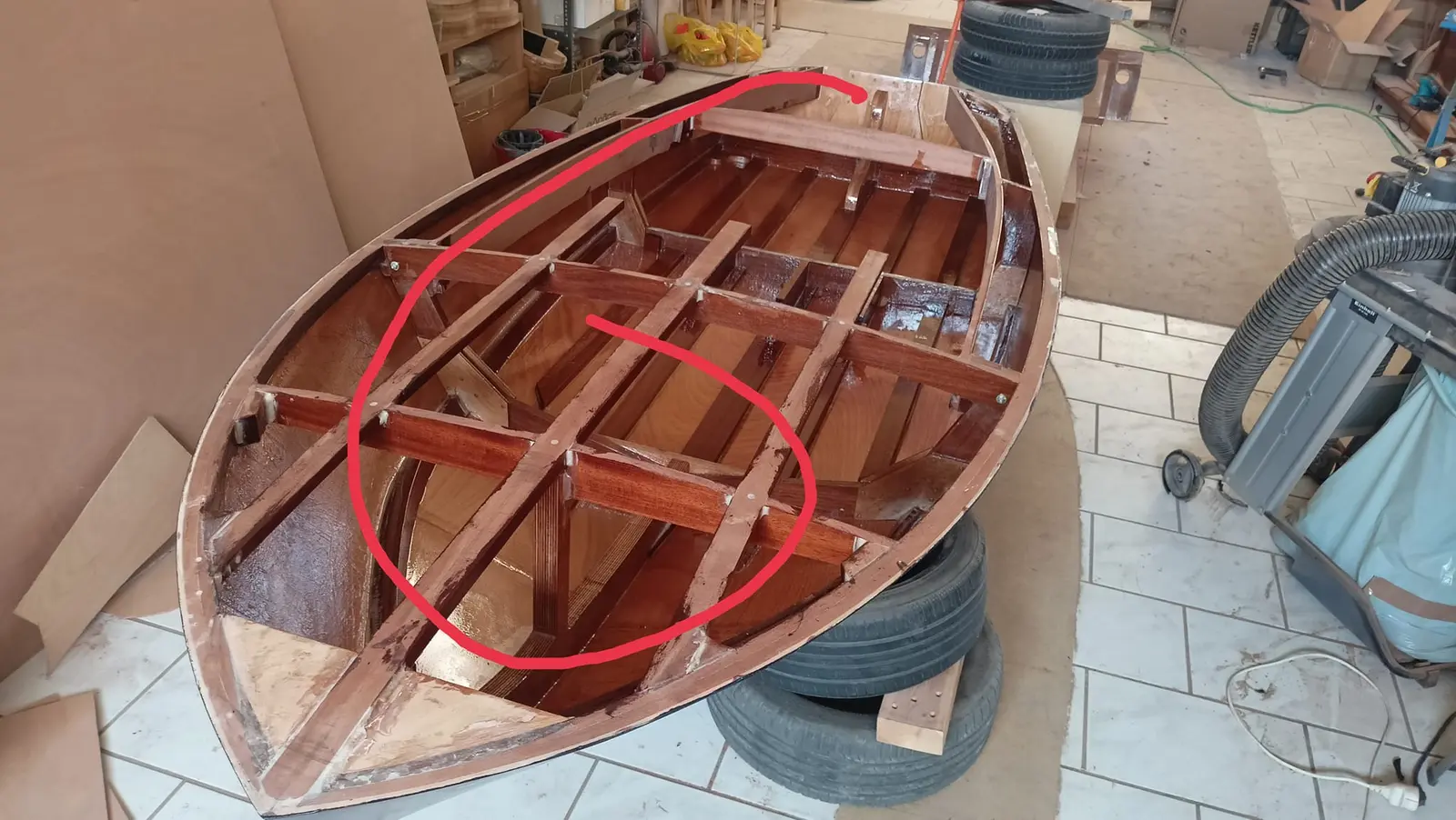
The cable I bought first was 14 feet, because it cannot take tight bends. For that reason the steering system will be mounted upside down and the cable will make a loop at the forward end of the boat. In the end 14 feet was not enough and I went to 16. To understand what I mean, look at the photograph and sketch below. The first sketch shows where the problem would have been.
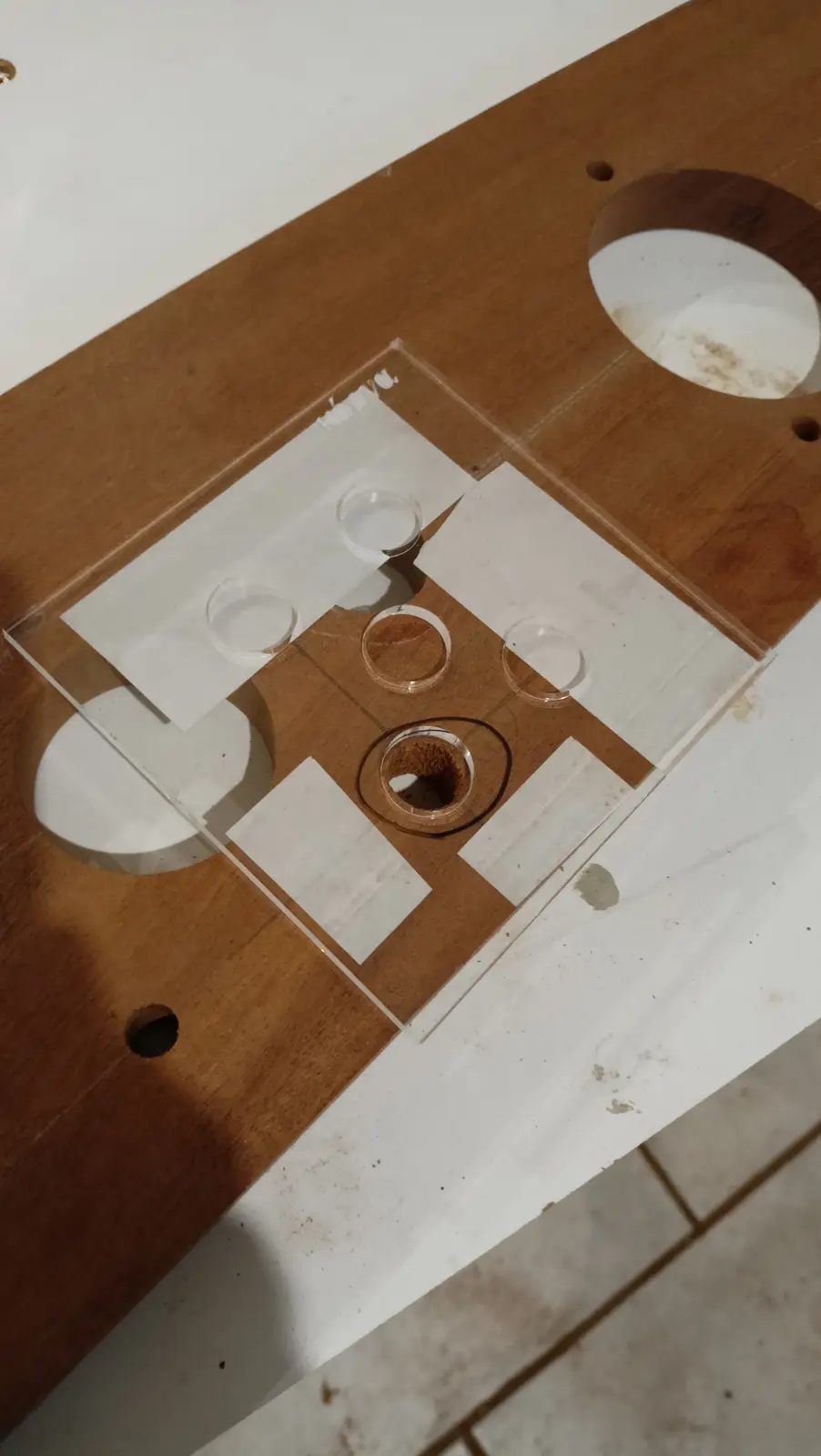
Alongside the dashboard I am also working out where the control box will go. I decided to put it lower than the coamings. So again I made a template on the laser.

The control box is a flush mount. So the mechanism will be inside and only the lever will show. It may need extra reinforcement inside and a mounting for the control box.
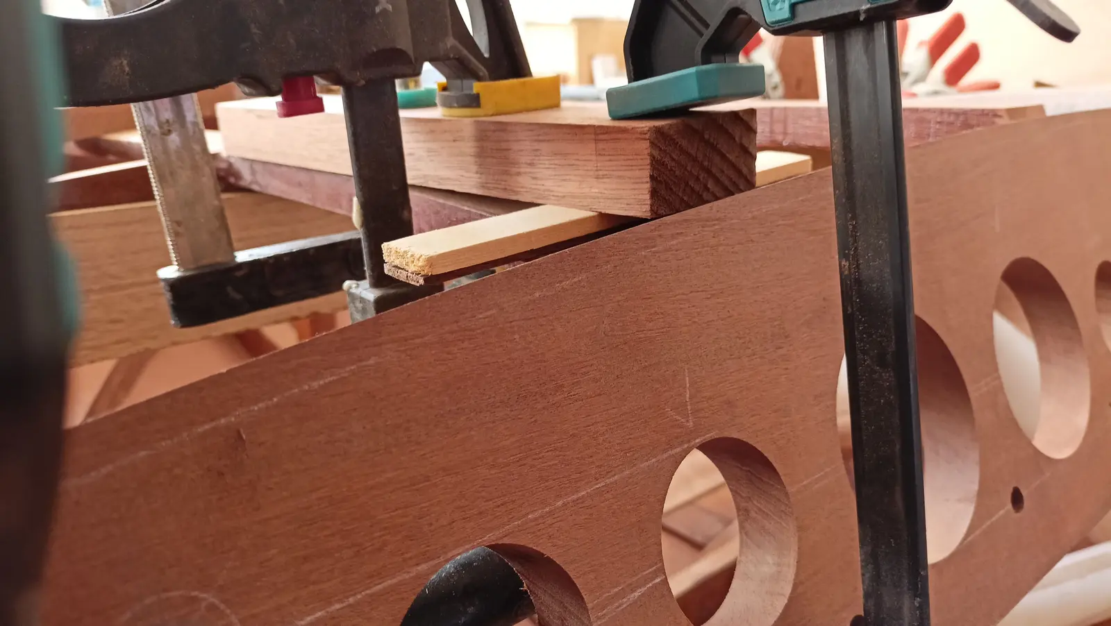
I have left a four centimetre margin on the top edge of the drawing so I can cut it at whatever angle is needed, so the inner part of the control box is not visible from behind (to change the mounting angle). It has three mounting positions, so there should not be a problem, but I left the margin to be sure.
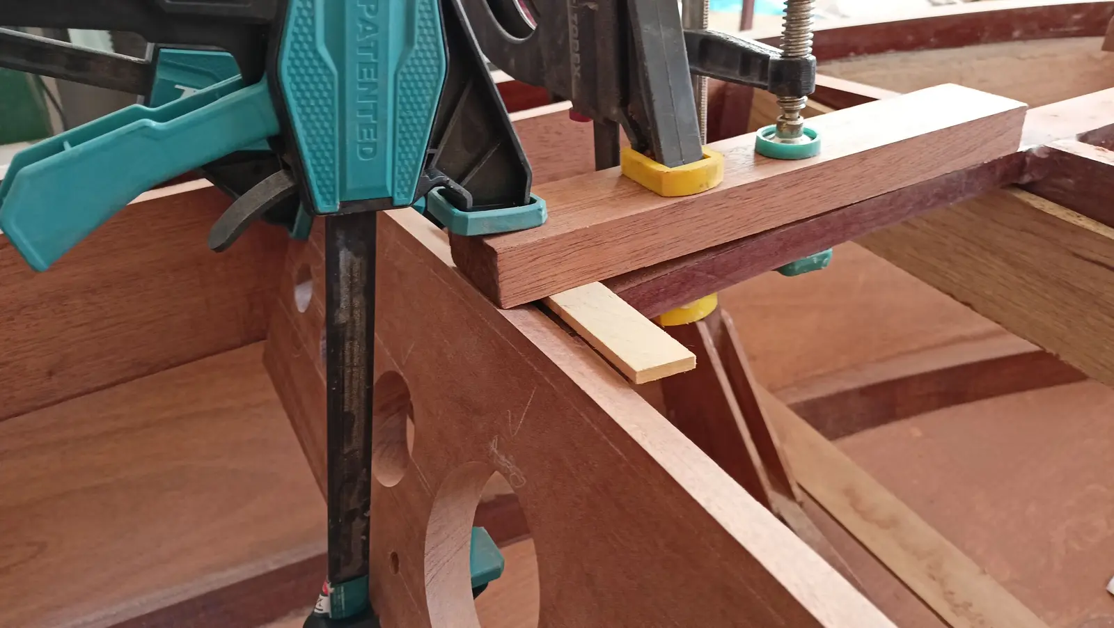
The holes were cut in exactly the same way as on the dashboard.

Back to the dashboard work. Some small changes were made, since in practice I saw that some instruments were a little cramped at the back, where all the cabling will be. In the end we settled on the arrangement below.

With the bending equipment I tried to put a little curve into the three uprights the dashboard will be glued to, so they came to the right height. The test was done by offering the dashboard up temporarily to see the height they needed to come to.

Then the packers that would support the dashboard at the sides were glued onto the coamings.

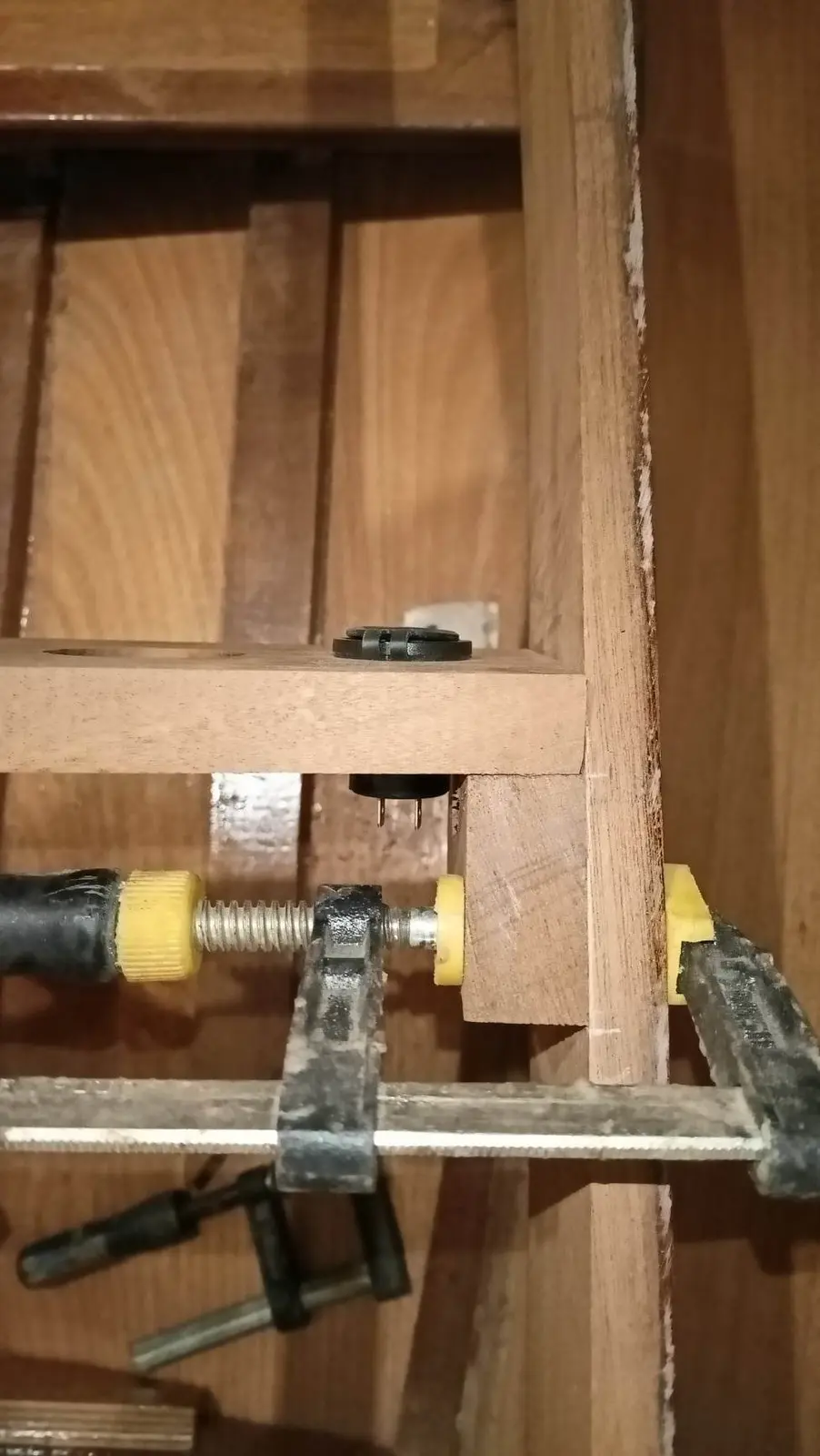
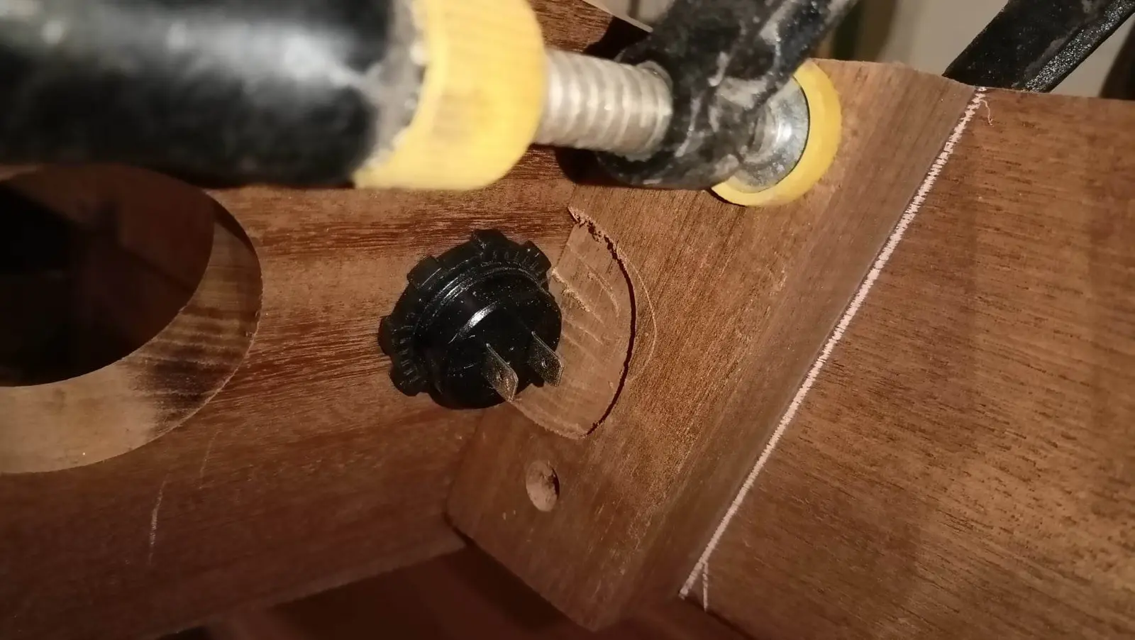
On one side, because the USB will be very close to them, a little had to be taken off the inside face so its clamp could be screwed on.

Finally, because the dashboard is thick for fitting the switches and the horn, its thickness was reduced slightly with the router.

The final instrument layout on the dashboard is below.

The next job is routing the curve on the lower edge of the dashboard so that at the ends its width matches the width of the coamings, rounding it over, and then gluing the dashboard onto the coamings.

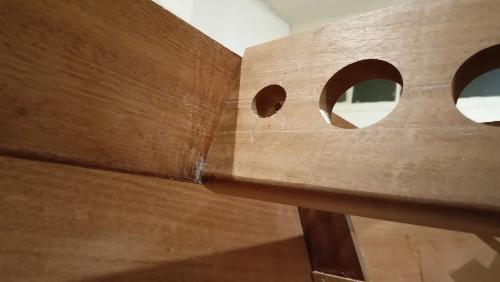
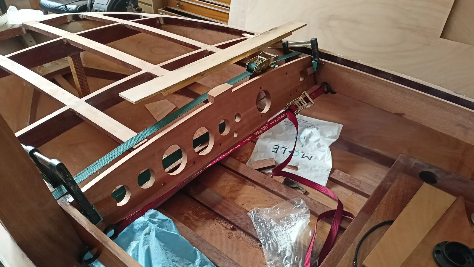
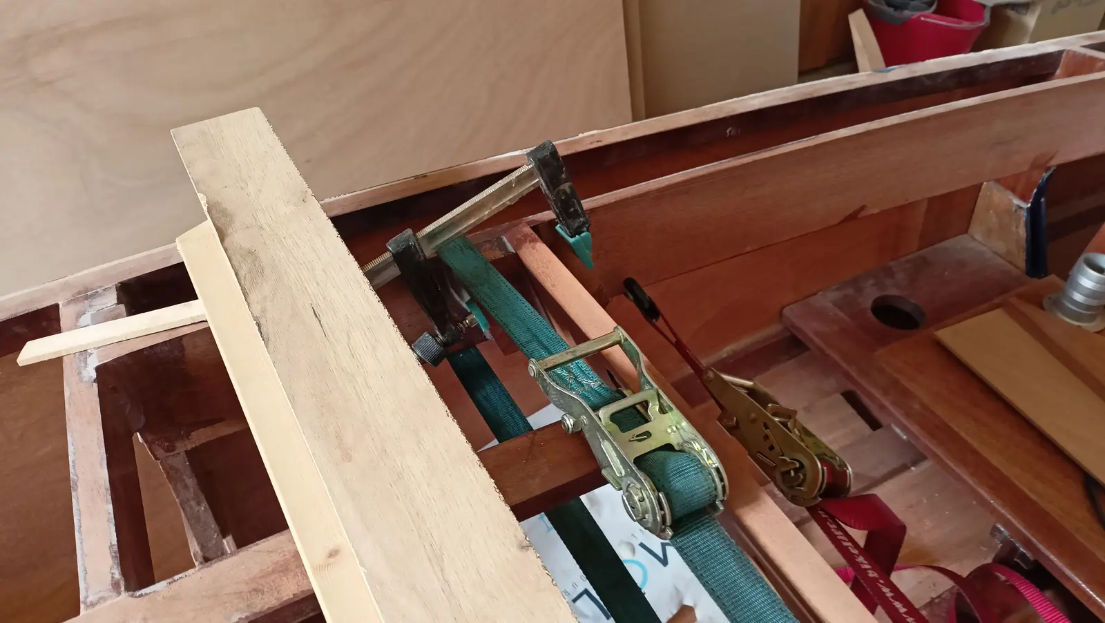
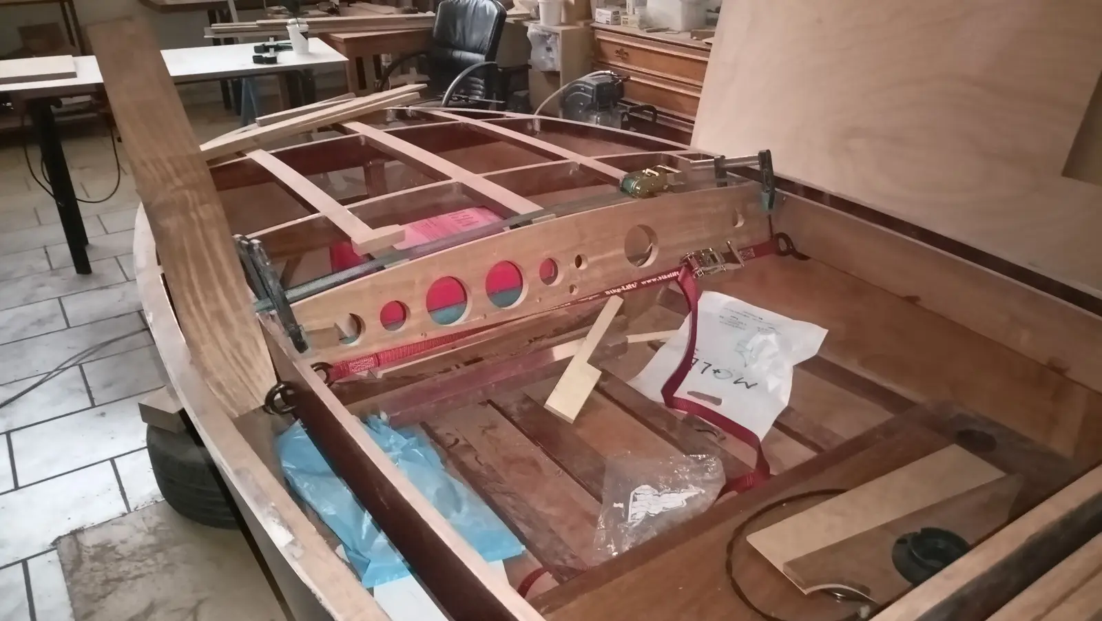
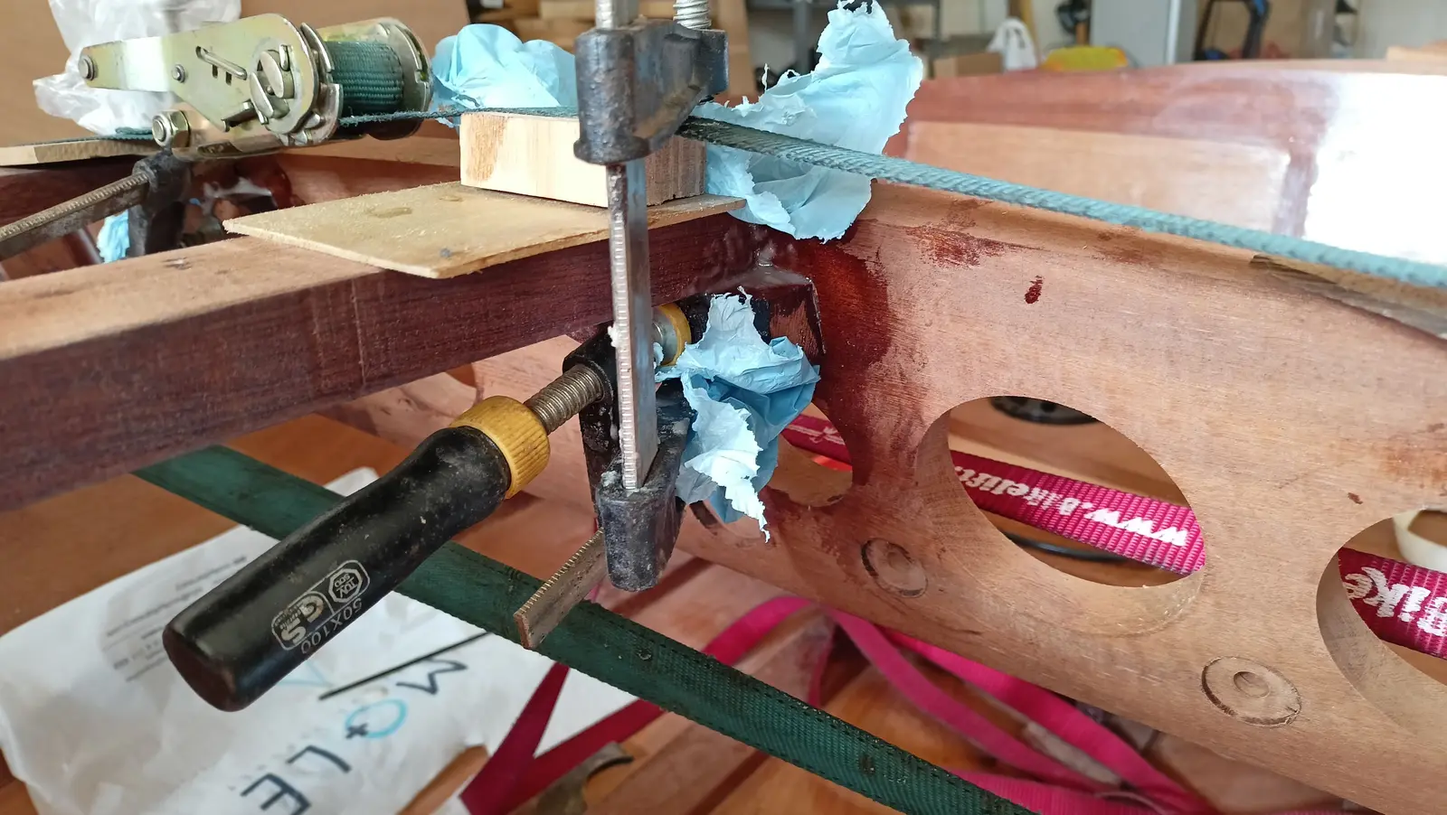
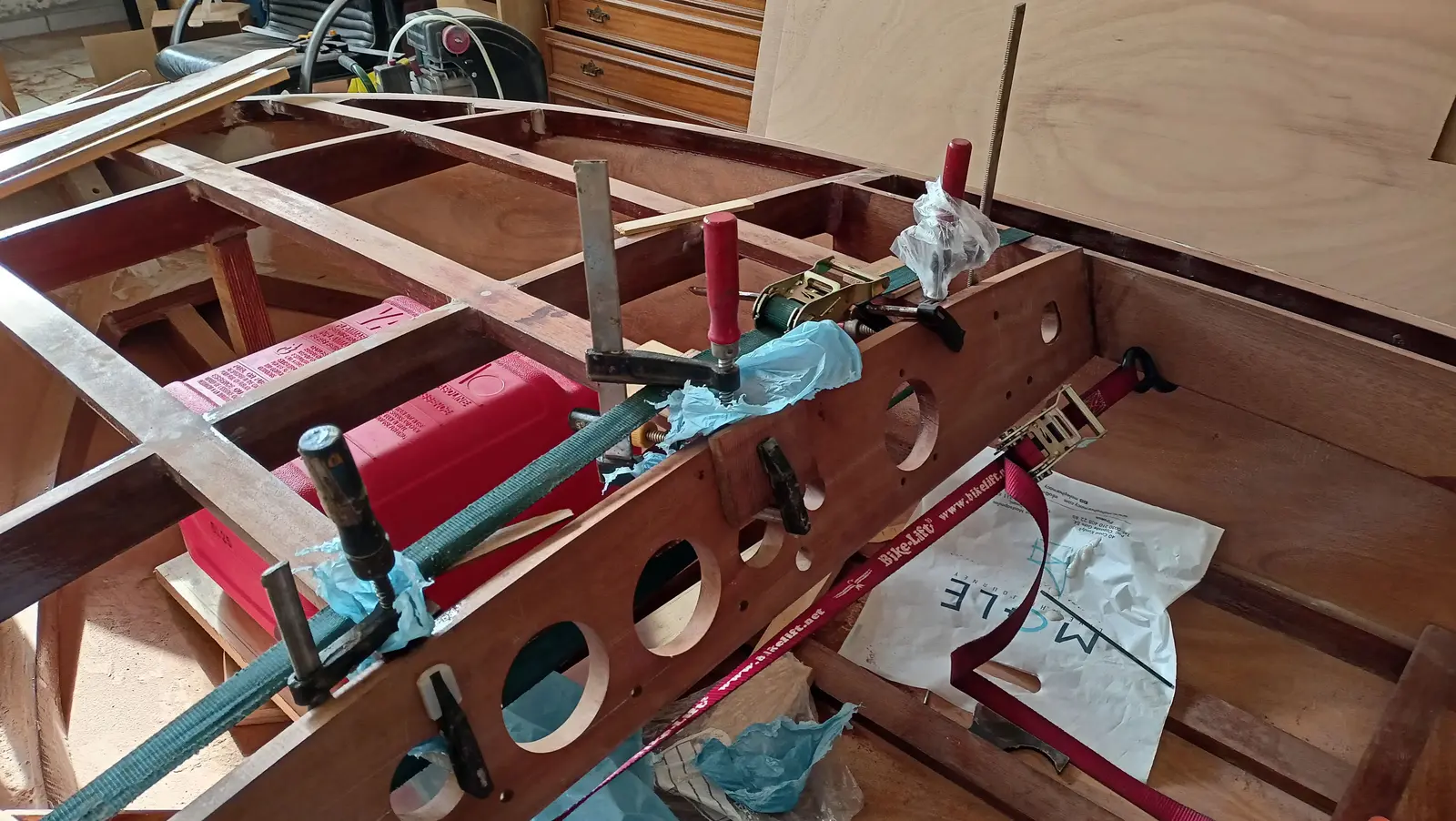
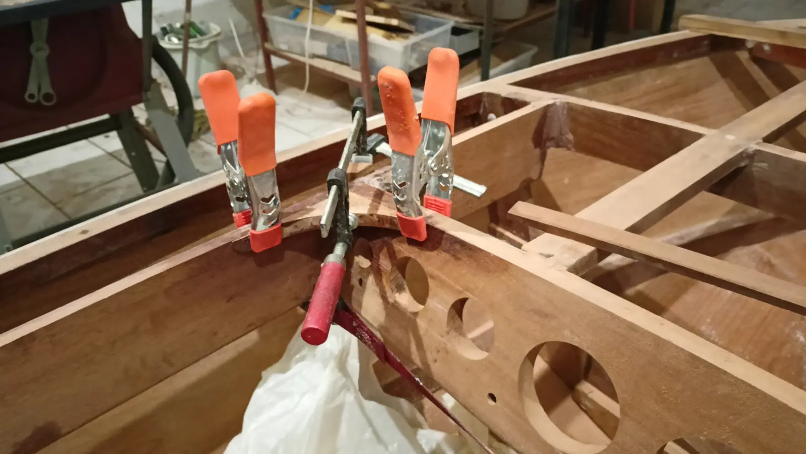
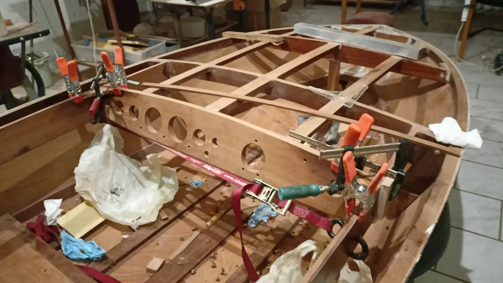
For the glue-up, straps were used as well as clamps, so as to close up the smallest gap that might be there.

The red strap was used for the gap, while the green one helped bring the three athwartships pieces down to the right height.

It was glued to the coamings first and then to the three athwartships pieces, so it went into its exact position.

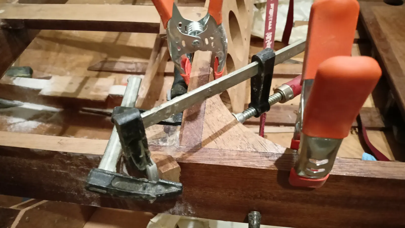
Those were then glued as well, after first making blocks so they bedded properly against the dashboard. The photographs of the work are below.

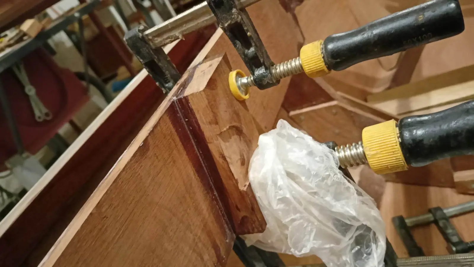
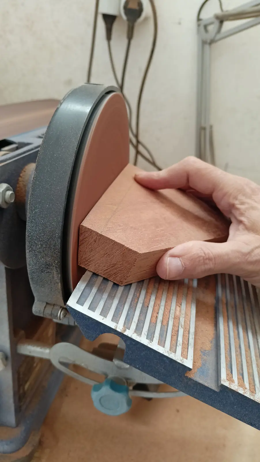
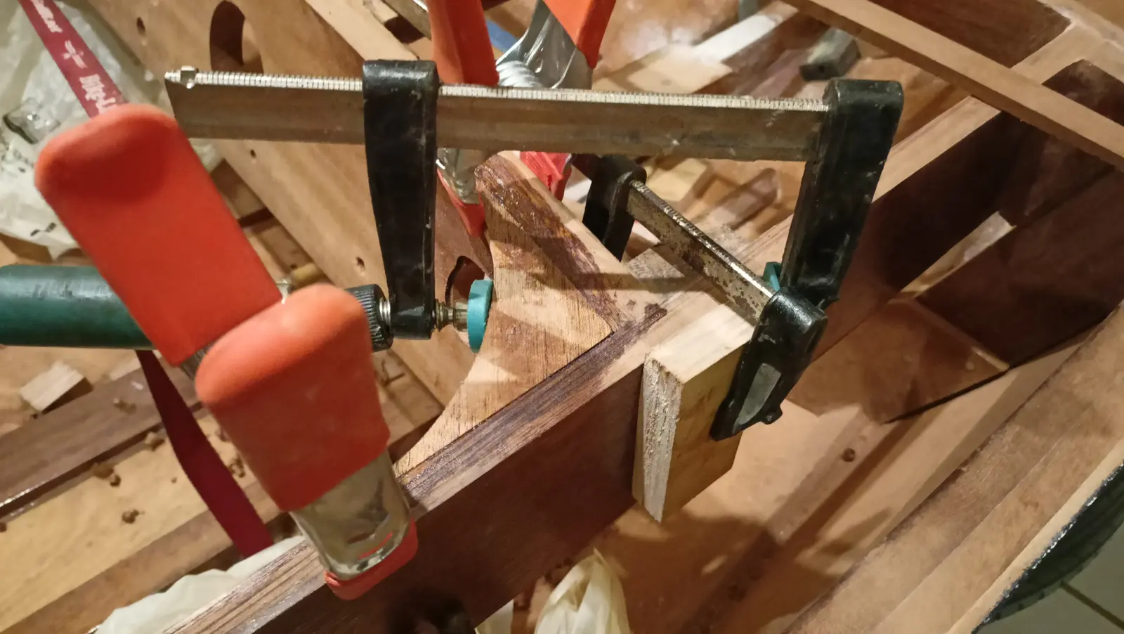
Then the curved pieces were made that join the dashboard to the coamings, which the plywood will sit on, for the look of it. The difficulty in making them is that angles have to be cut on the two inner faces so they can be glued.

The last job for the dashboard was gluing those in. Because underneath them there is the engine key on one side and the USB on the other, I took their thickness down a little so they would fit. The curve was cut to a 23 cm radius and they were glued on.

What it cost

€8,936.64
€7,767.94
Into the boat
€1,168.70
Tools & gear
ItemQtySupplierCost
Timber for the building base n/a n/a €120.00
Glen-L Squirt plans 1 n/a €78.00
Screws and nails n/a n/a €183.23
Plexiglass template stock, laser cut 1 n/a €43.00
Plywood for the frames and transom 2 x 7 mm, 1 x 20 mm n/a €160.00
Sapele for the frames 3 n/a €150.00
Screws for the building base n/a n/a €12.00
Epoxy resin 5 litres n/a €222.00
Microfibre filler 10 lt n/a €14.67
Fiberglass cloth 20 n/a €44.00
More marine plywood 4 x 6 mm n/a €236.00
Rollers and sundries n/a n/a €35.00
Brushes n/a n/a €14.00
Silicon bronze screws from England, No. 2 n/a n/a €50.00
Galvanised carriage bolts n/a n/a €10.00
Tools: router, sockets, drill bit n/a n/a €110.00
Disposable gloves n/a n/a €10.00
Packaging bags for steam bending n/a n/a €15.00
Steamer n/a n/a €70.00
Alignment laser n/a n/a €22.00
Forward mooring cleat 1 n/a €15.00
Aluminium angle for the table saw n/a n/a €13.00
Scales n/a n/a €6.00
9.5 mm drill bit for the cleat n/a n/a €5.00
Forward mooring cleat n/a n/a €14.00
Microballoons n/a n/a €9.70
Speedometer n/a n/a €80.00
Battery gauge n/a n/a €40.00
Horn and button n/a n/a €76.00
Spiral screwdriver n/a n/a €32.00
Aft mooring cleats 2 n/a €22.00
Brushes and rollers n/a n/a €30.00
Cleats 2 n/a €18.00
Sipo, 3350 x 170 x 65 0.037 m3 n/a €80.00
Joiner's fee n/a n/a €150.00
Brushes 60 n/a €37.00
Cable ties, 37 cm 1 pack n/a €7.00
Spring clamps 70 n/a €63.00
Sipo, 3350 x 140 x 65 0.03 m3 n/a €60.00
Brushes 60 n/a €19.00
Corrugated card 8 m n/a €5.00
Stainless coffee cup holders 2 n/a €7.50
Fuel gauge 1 n/a €9.00
USB and 12 volt socket n/a n/a €6.00
Screws and plastic washers for planking 100 + 100 n/a €7.00
Screws and plastic washers for planking 100 + 100 + 100 + 50 n/a €15.00
Resin mixing sticks 100 n/a n/a
Epoxy resin 5 litres n/a €223.00
Epoxy primer 1 litre n/a €56.15
Timber for the second building base n/a n/a €30.00
Fiberglass cloth, 213 g/m2 n/a n/a €123.70
Roller trays, 20 mm 2 n/a €3.00
Epoxy fairing filler n/a n/a €24.00
West System resin rollers 8 n/a €65.00
Resin rollers, 9 in 2 n/a €18.00
Double-sided tape n/a n/a €1.00
Dowels, 10 mm n/a n/a €4.00
Chandlery: lights, switch, pumps n/a n/a €262.60
Yamaha 25 hp GES EFI outboard 1 n/a €4,340.00
Flush-mount control box 6X3 1 n/a €170.00
Epifanes Polygloss Britannia Blue 3 n/a €135.75
Hempel epoxy filler 1 lt n/a €68.50
Hempel light primer 0.75 lt n/a €40.00
Thinner 0.75 lt n/a €18.00
Brush 1 n/a €6.50
Rollers 2 n/a €6.40
Rollers 3 n/a €7.50
Mixing pots 15 n/a €10.00
Rollers 14 n/a €8.00
Black brush 1 n/a €5.00
Water containers 3 n/a €19.50
Water container 1 n/a €8.00
Box section for the outboard dolly 6 m n/a €18.00
Dolly wheels, lower 2 n/a €18.00
Dolly wheels, upper 2 n/a €30.00
Machine shop, drilling the dolly axle n/a n/a €10.00
Locker catch 1 n/a €35.00
SeaStar TFX N.F.B. 4.2 steering helm 1 n/a €239.90
SeaStar SSC62 TFX Quick Connect steering cable, 16 ft 1 n/a €133.00
SeaStar TFX NFB 90 degree bezel kit 1 n/a €20.00
Osculati steering wheel 1 n/a €132.00
Fairleads 2 n/a €20.00
Locker catches, fore and aft 2 n/a €14.00
Pump outlet fittings 2 n/a €24.00
Brushes, 2 cm 40 n/a €14.00
Forward deck cleat 1 n/a €25.00
Fuel vent 1 n/a €30.00
Silicon bronze screws from England, No. 3 n/a n/a €46.00
Push switches 6 n/a €36.00
Cable tie bases for the wiring 20 n/a €4.24
Horn button, No. 2 1 n/a €7.00
Double-sided tape 1 n/a €1.80