boatbuildlog

Glen-L Squirt · new build

Glen-L Squirt

by George · Greece · Message George
Make a book Feed The whole log, 26 entries and every photo, laid out as a book to print, bind and keep.
26
Entries
371
Hours
1,858
Days elapsed
861
Photos
Spent
Link

Interior work No. 6

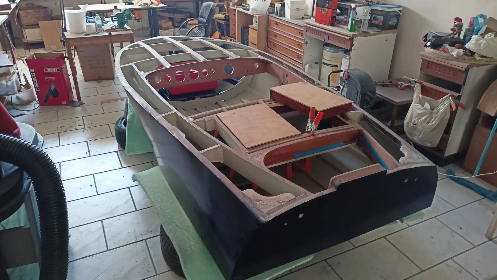
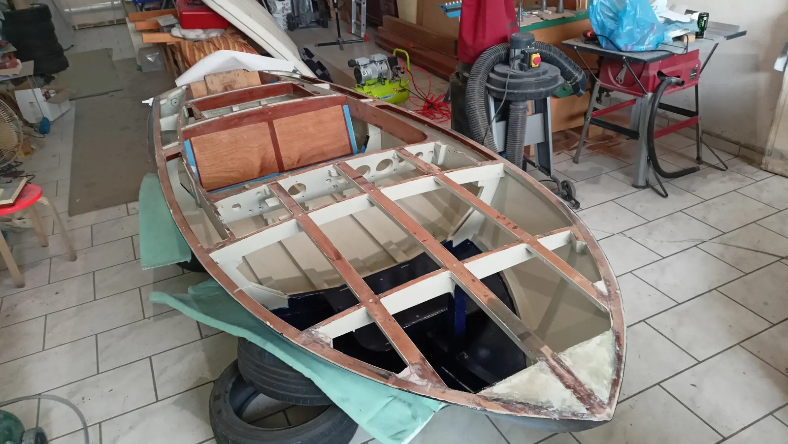
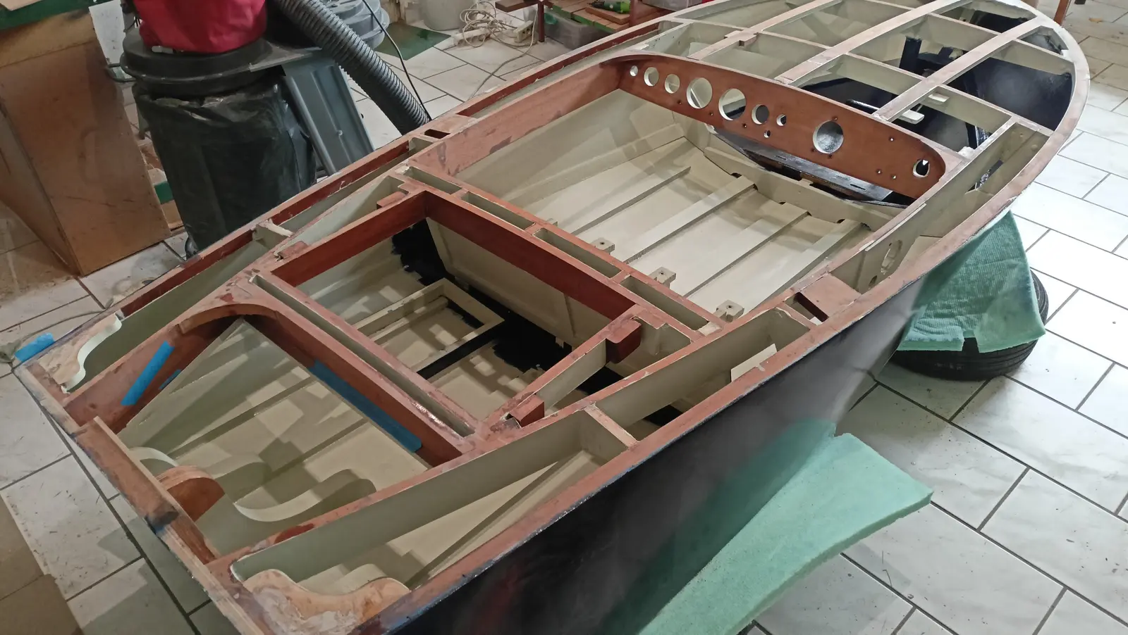
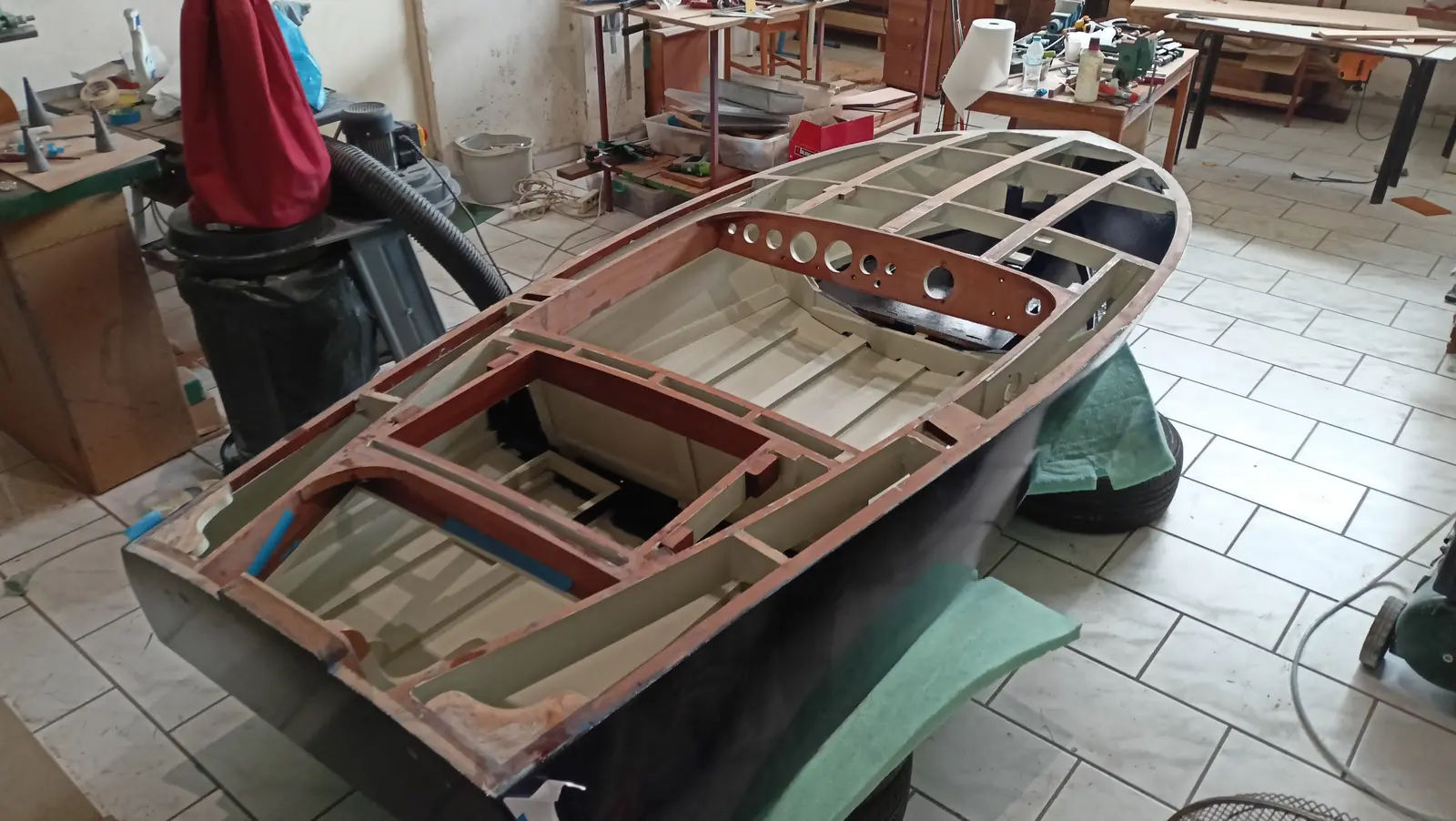
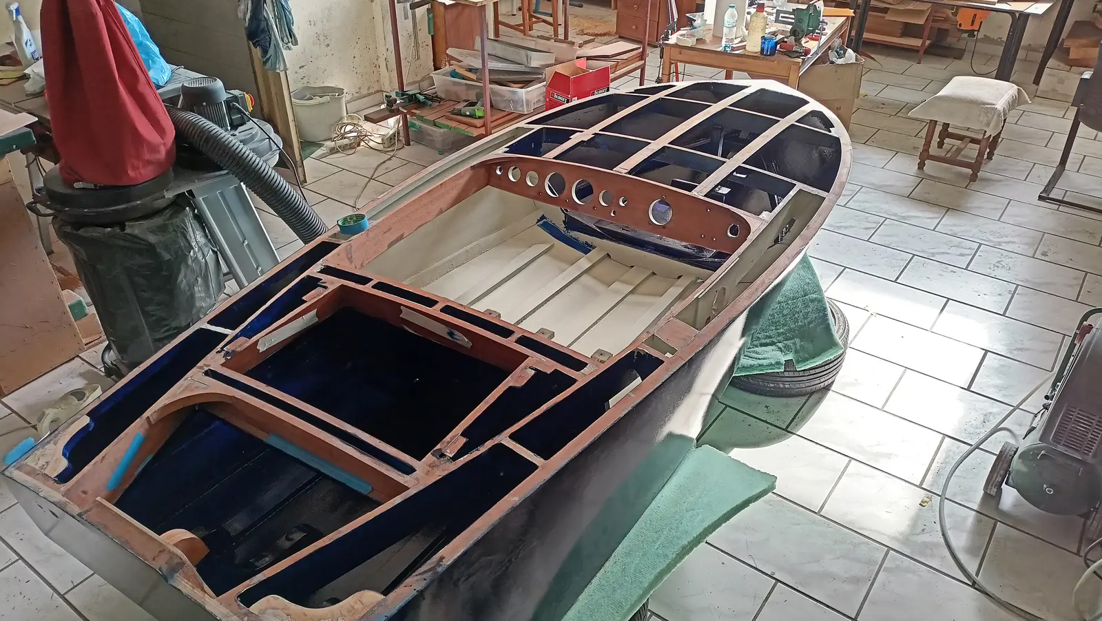
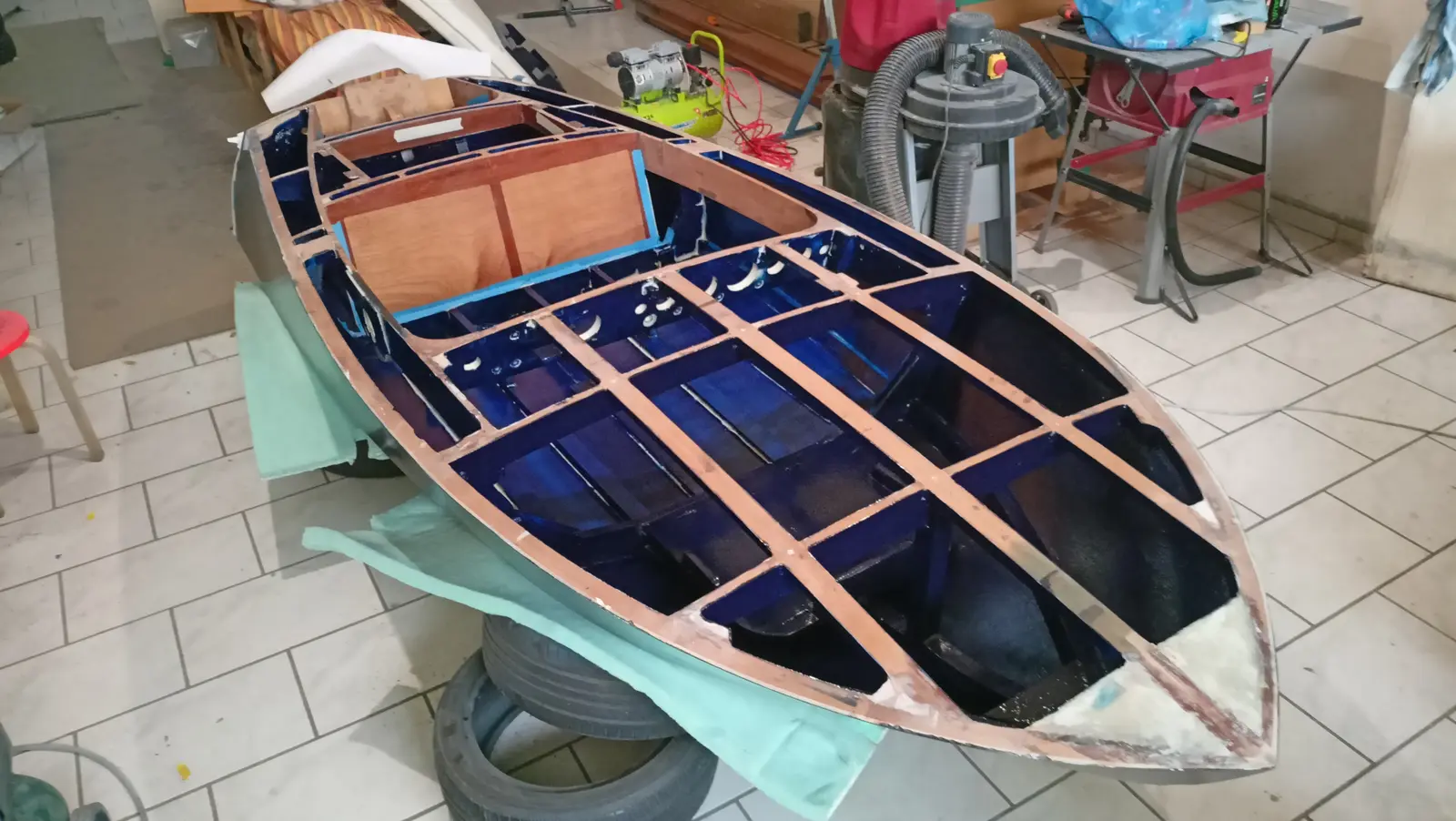
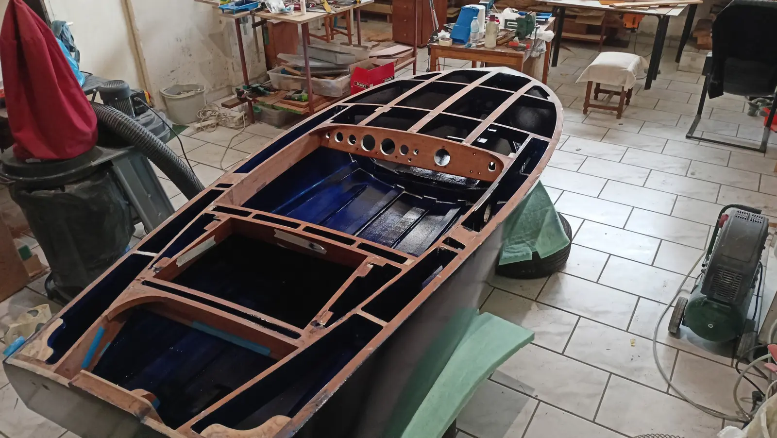
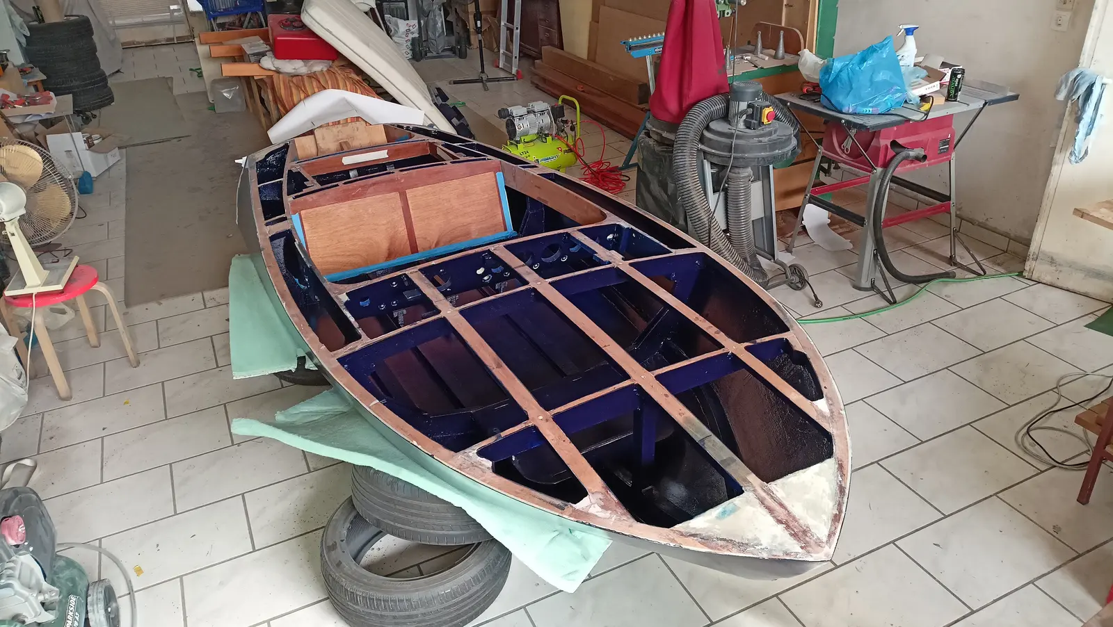
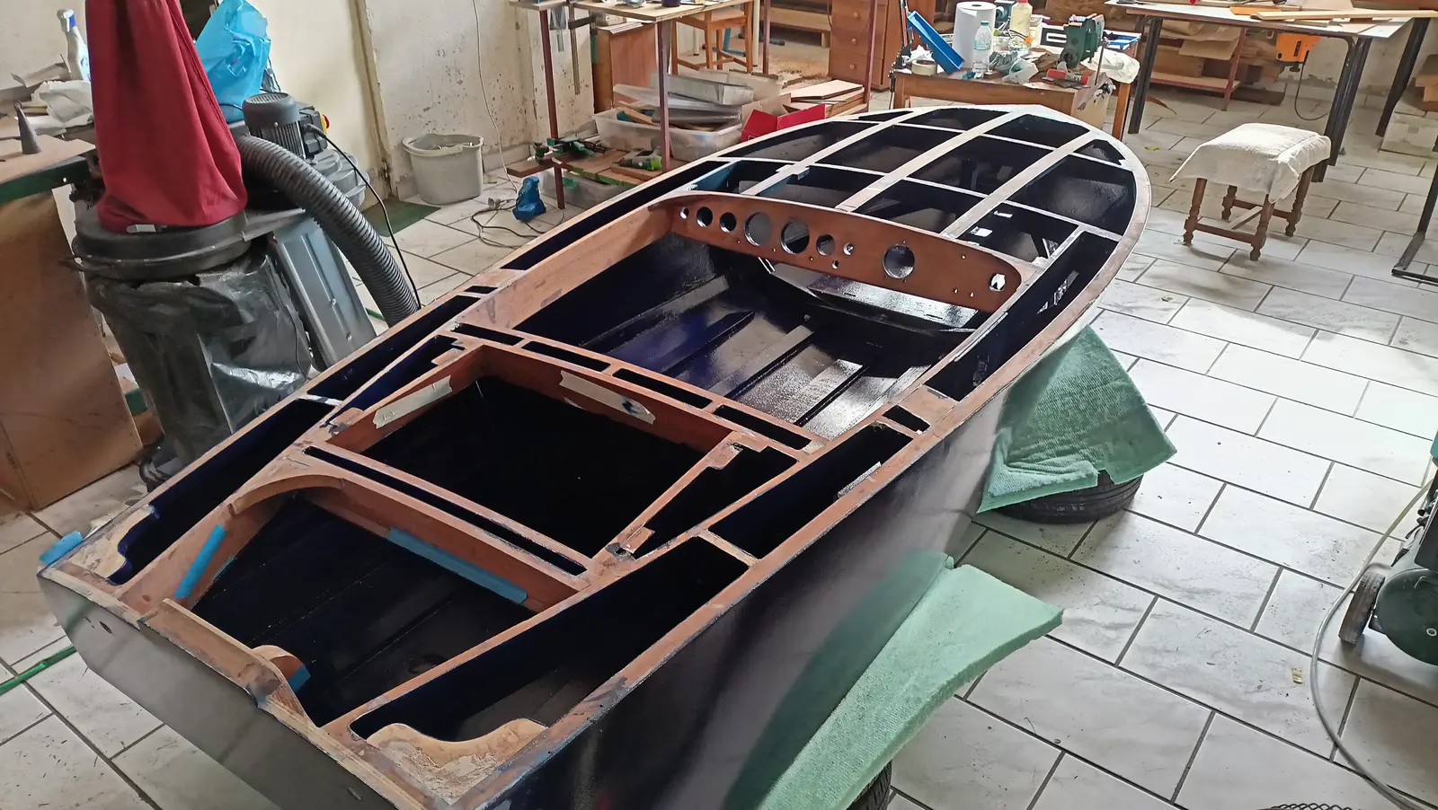
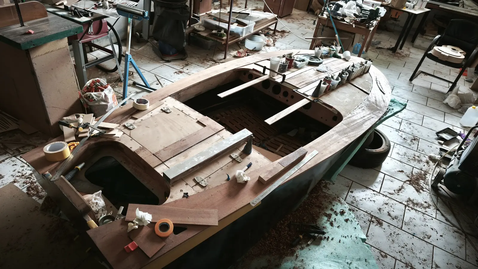
This article covers what are probably the last of the joinery jobs before the deck is closed in.

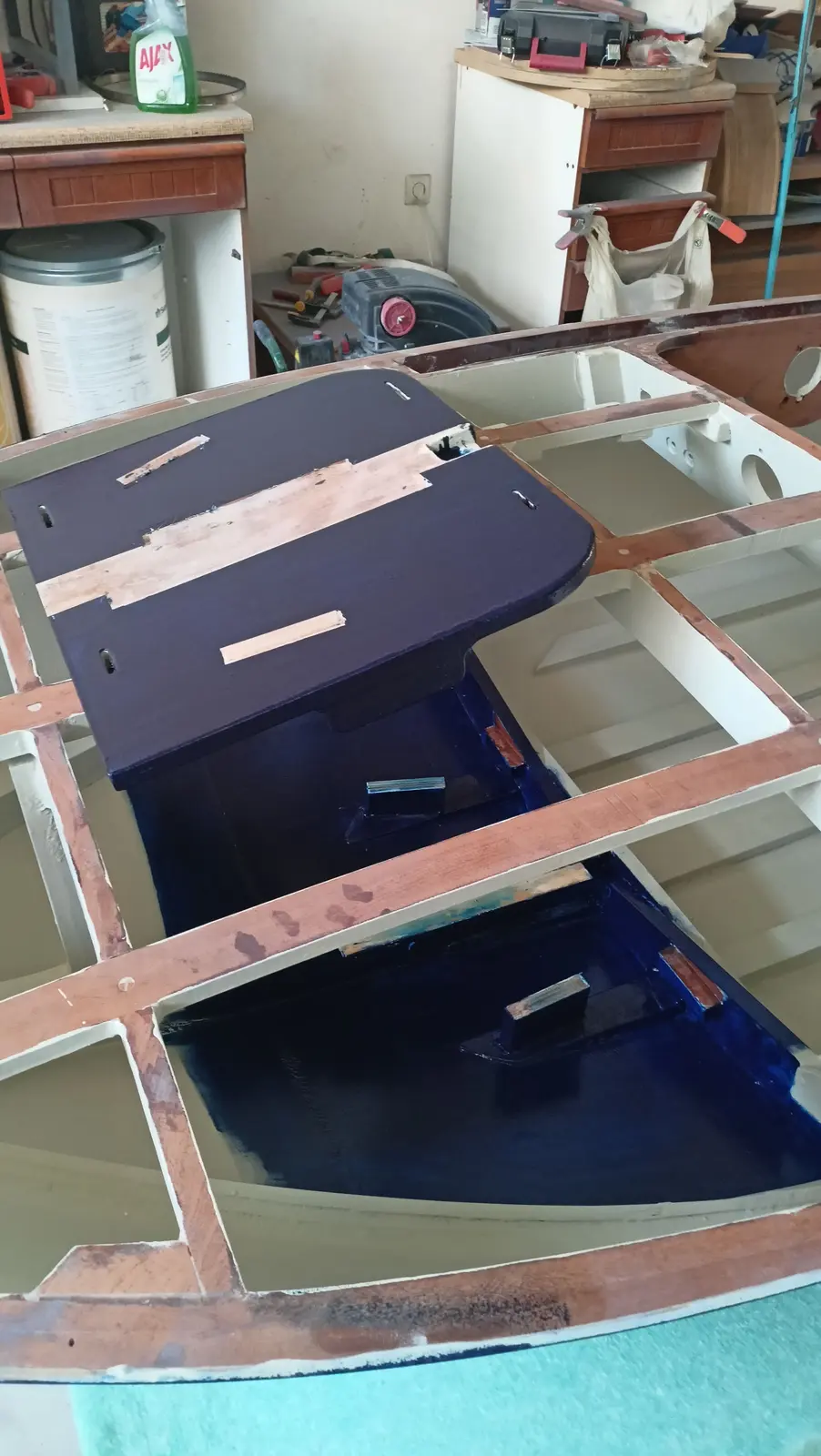
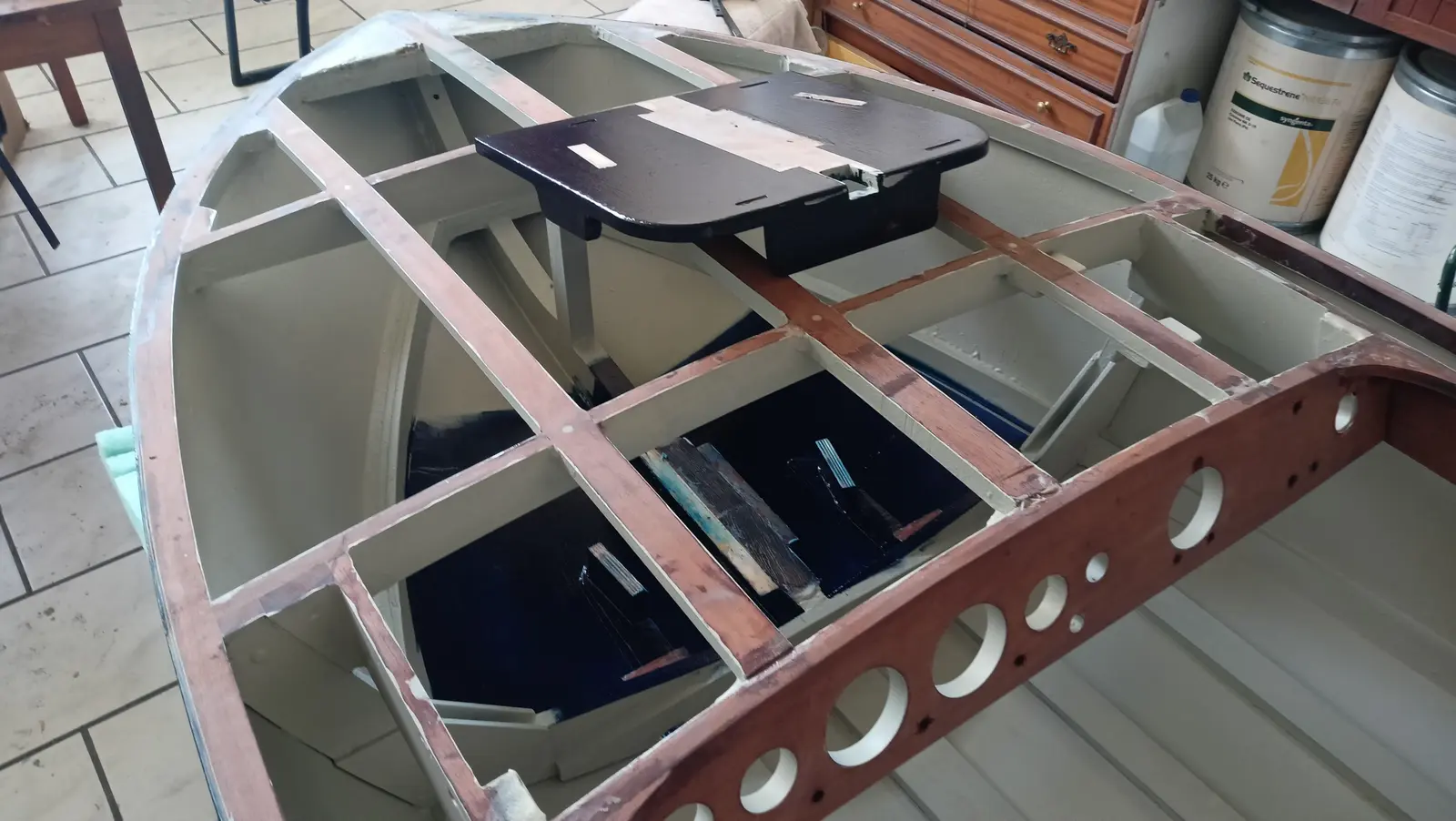
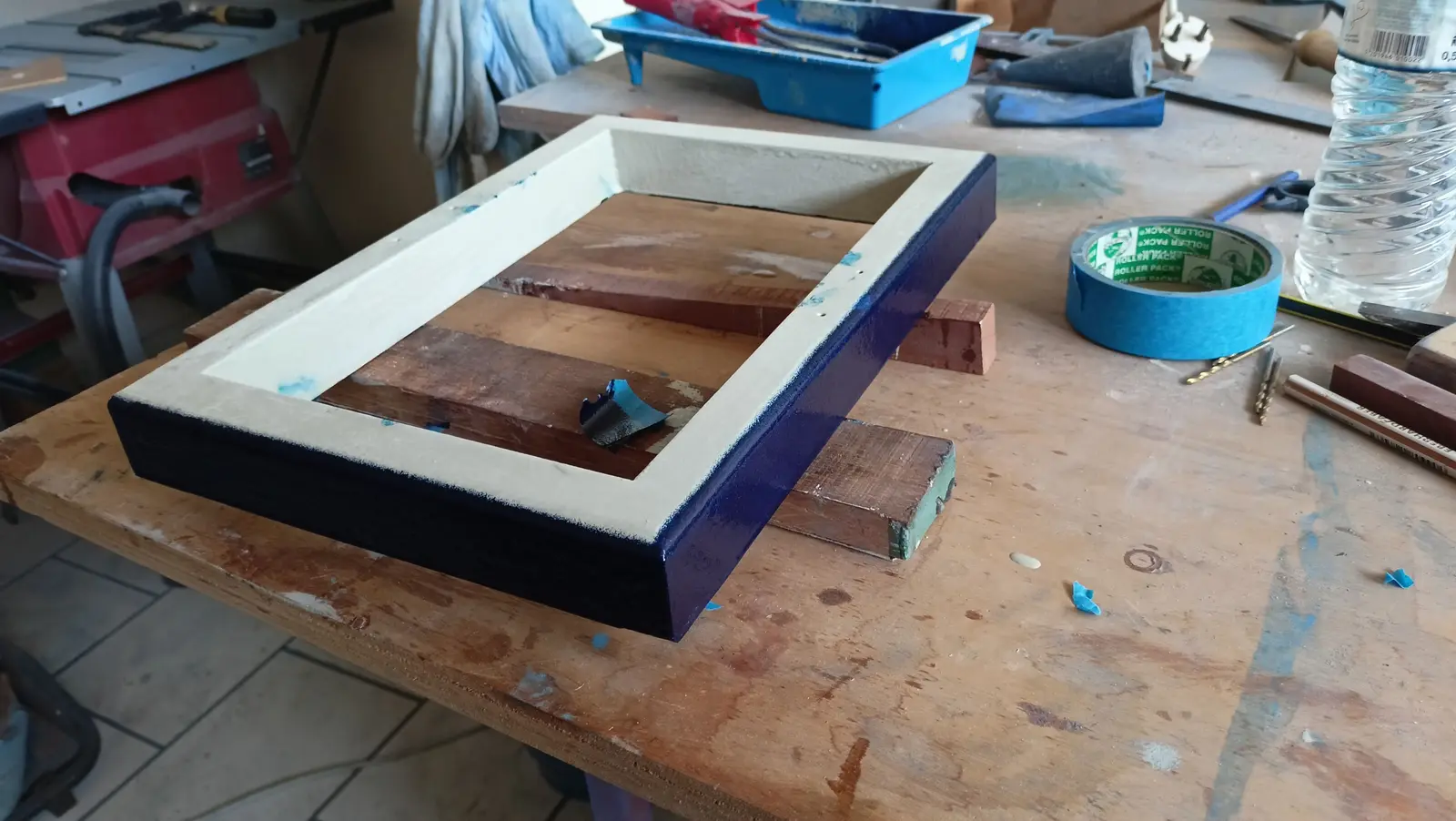
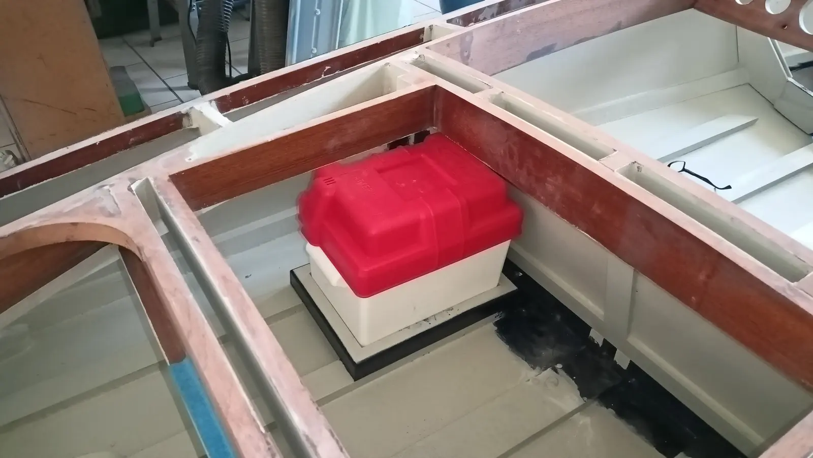
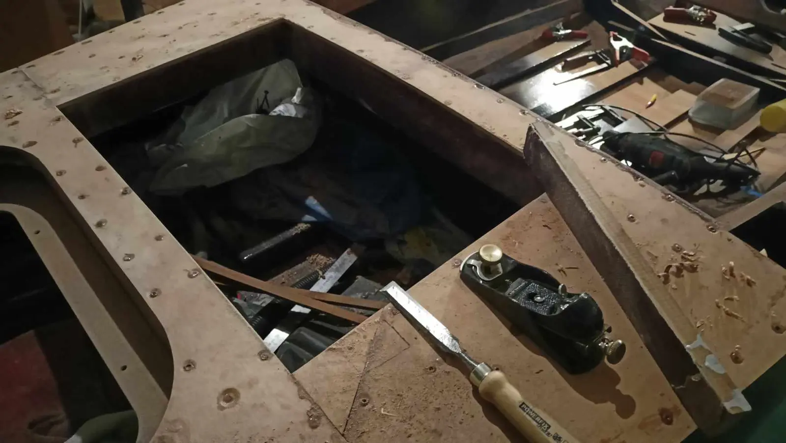
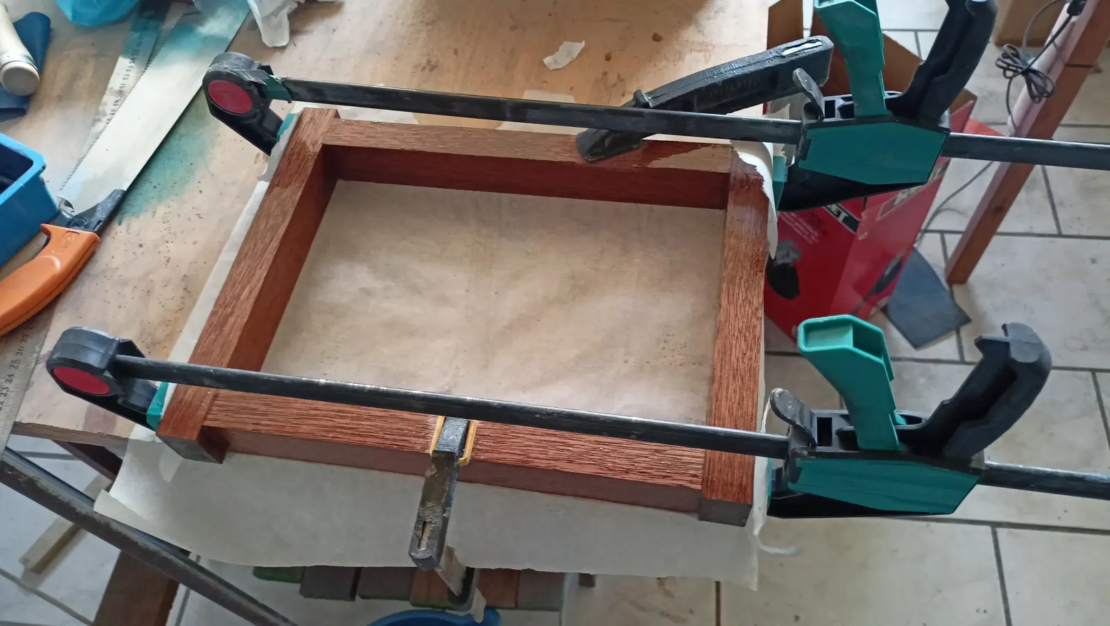
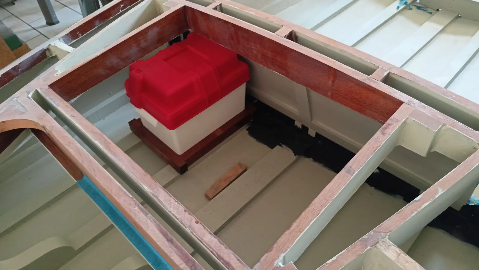
First I started work on the battery box. The box will be installed on the bottom of the boat on its fore-and-aft timbers. A frame was made that it drops into.

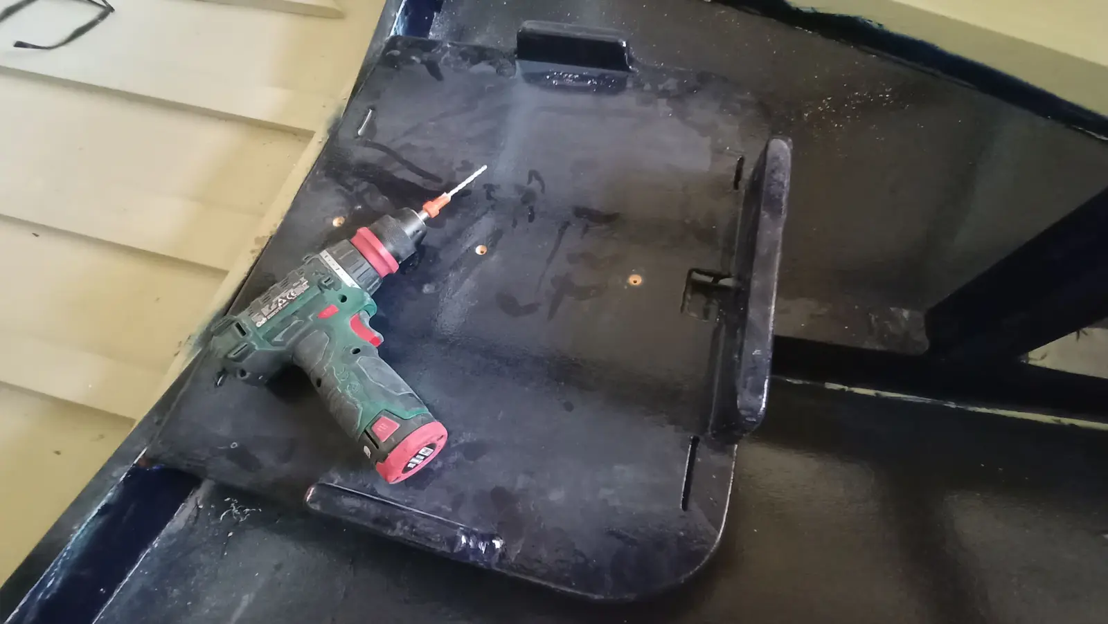
So that water has no contact with the timber at all, I decided every screw would sit in epoxy. For that reason oversize holes were drilled and filled with epoxy and microfibre. The outer faces of the base were also routed.

The epoxy primer was removed from the bottom of the boat where the base will be glued.

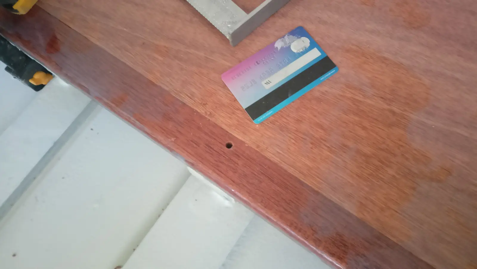
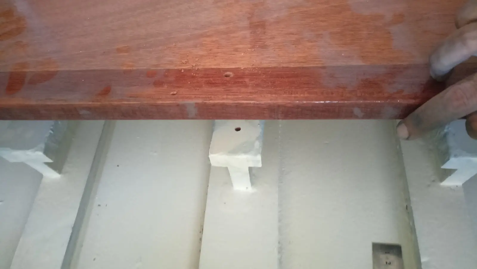
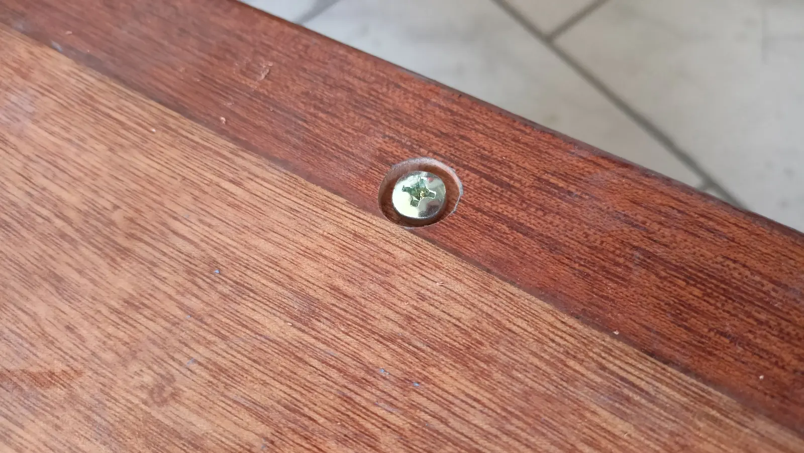
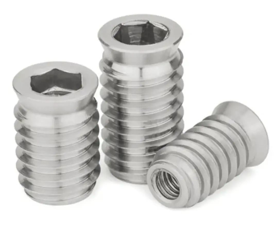
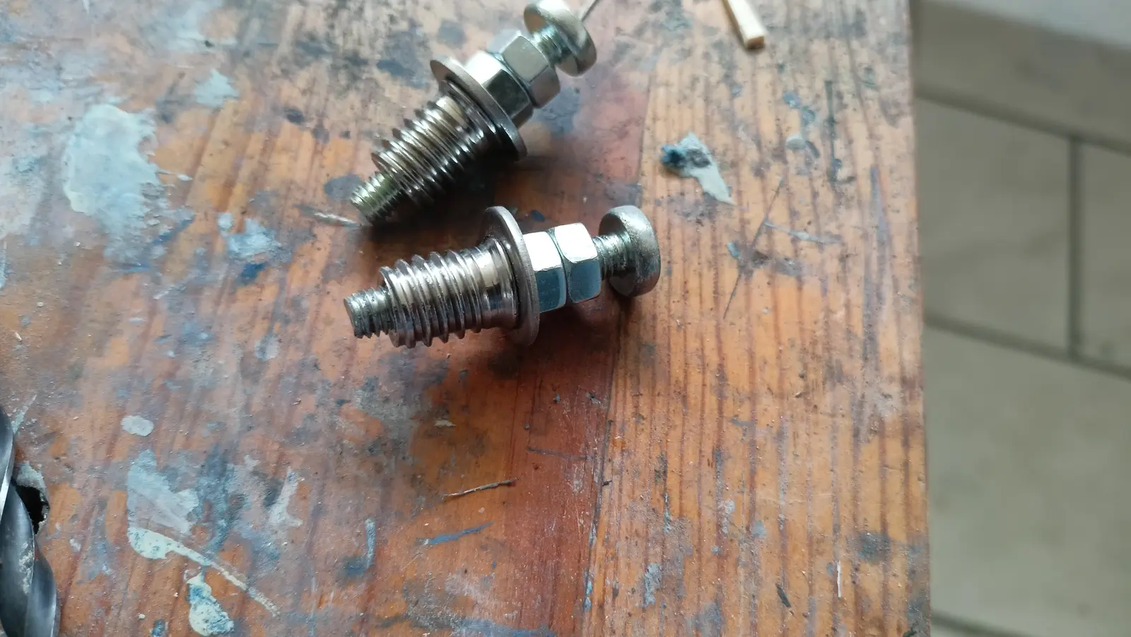
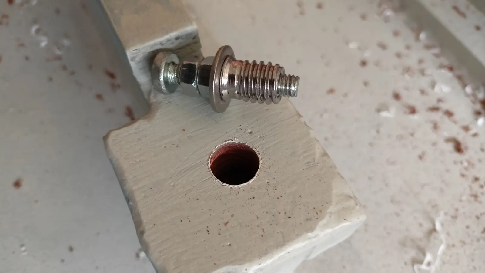
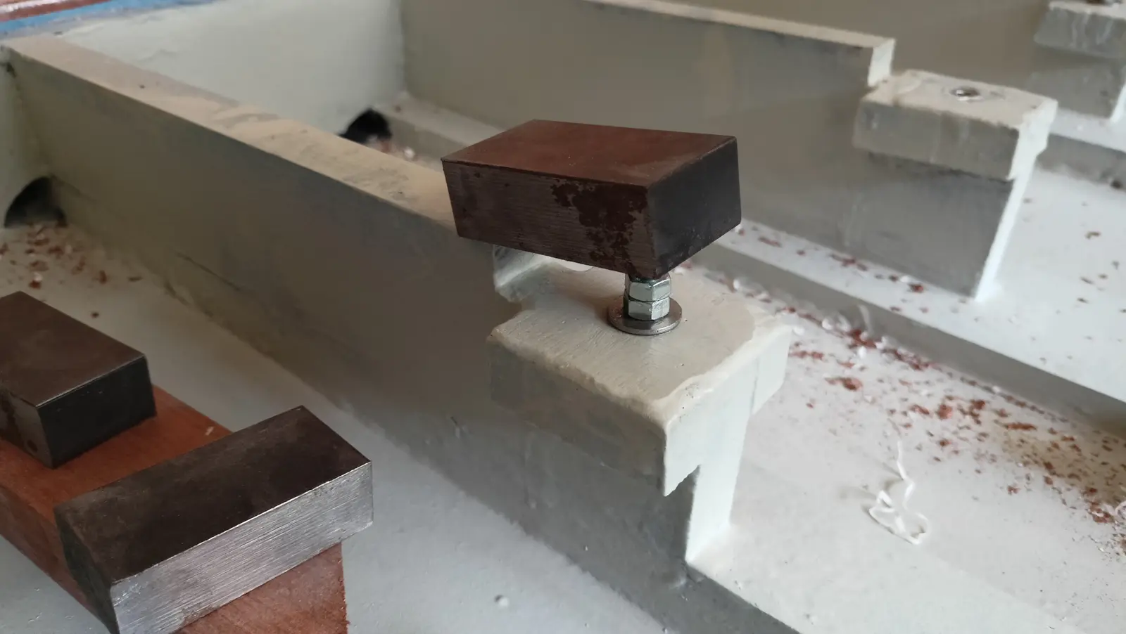
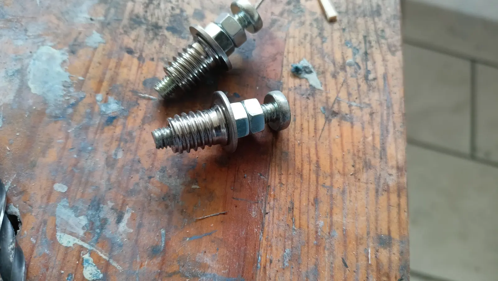
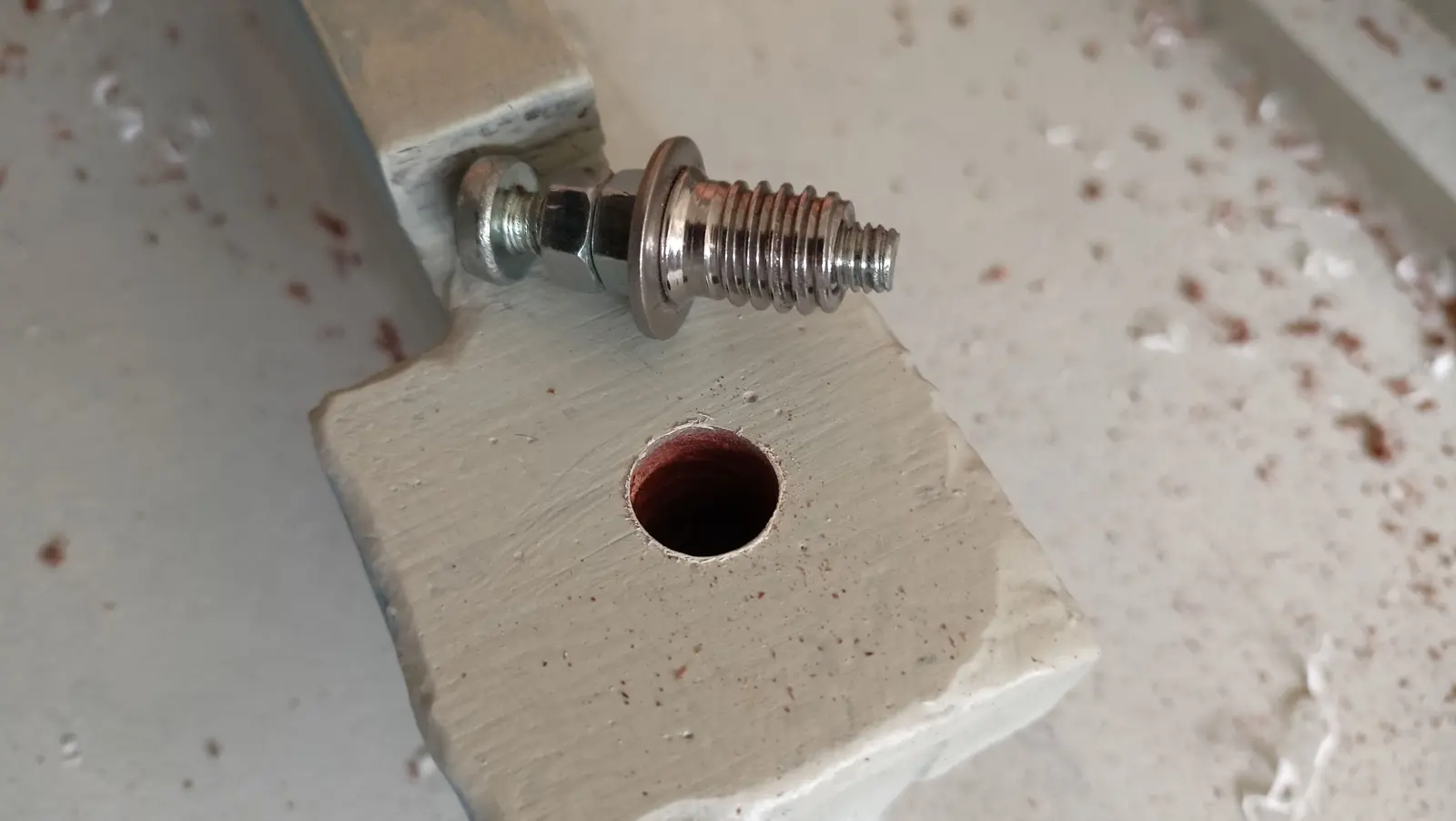
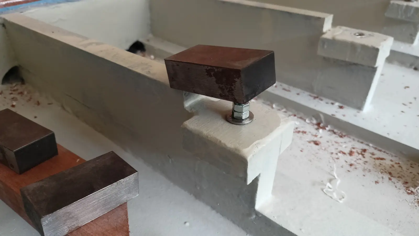
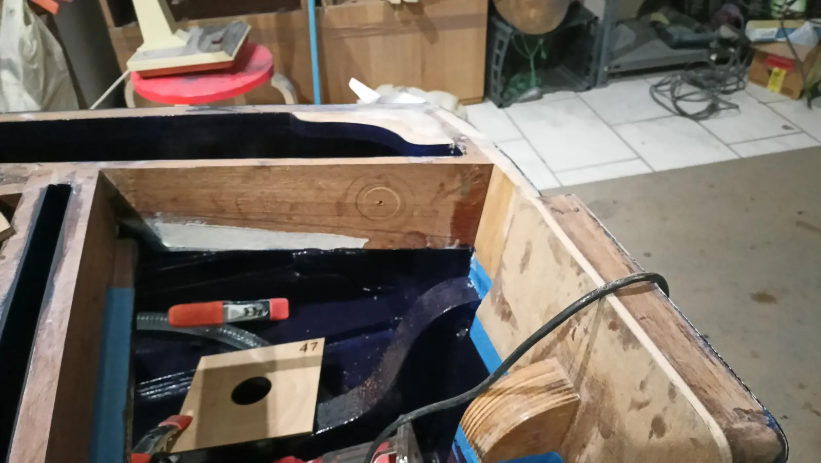
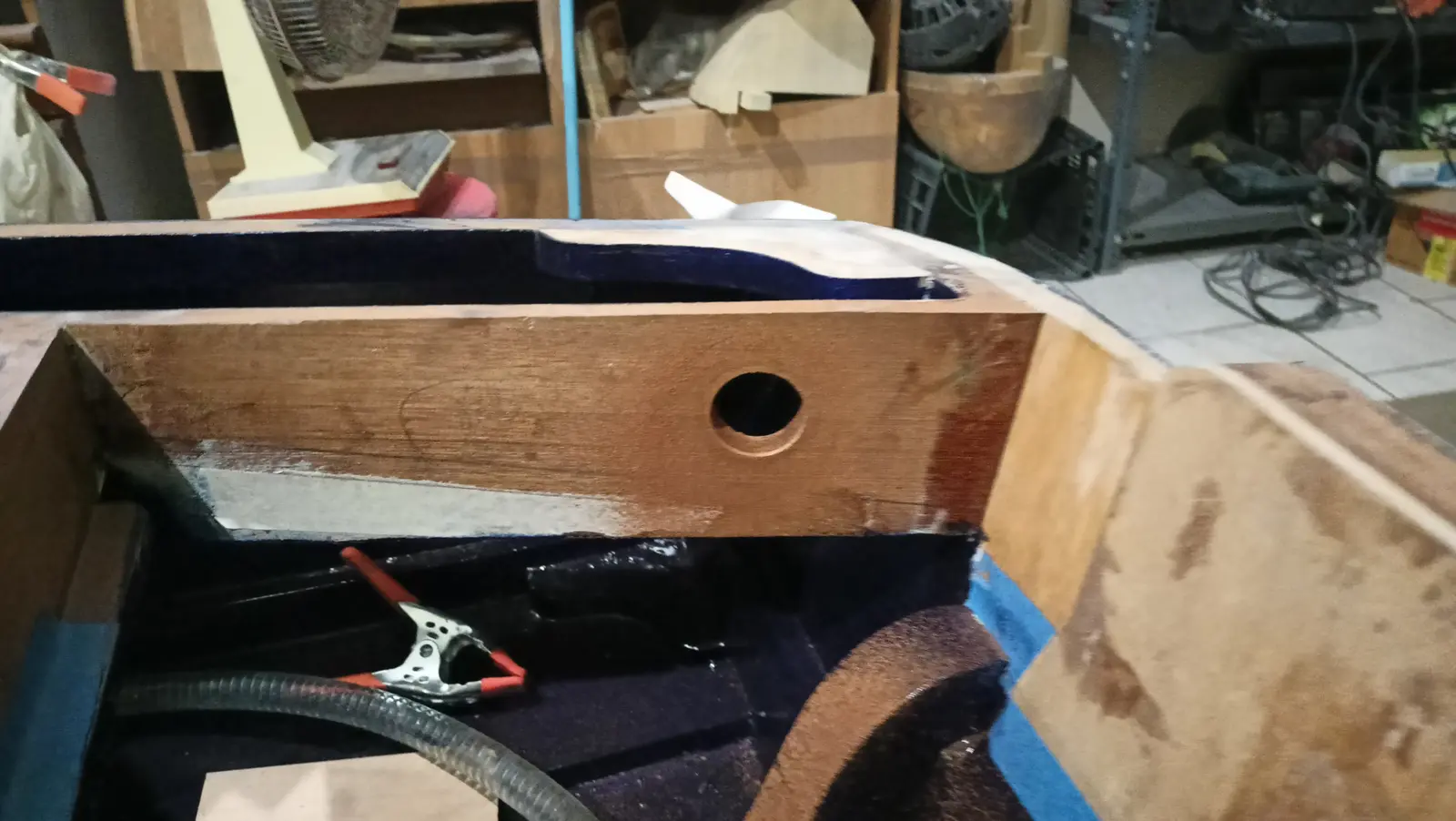
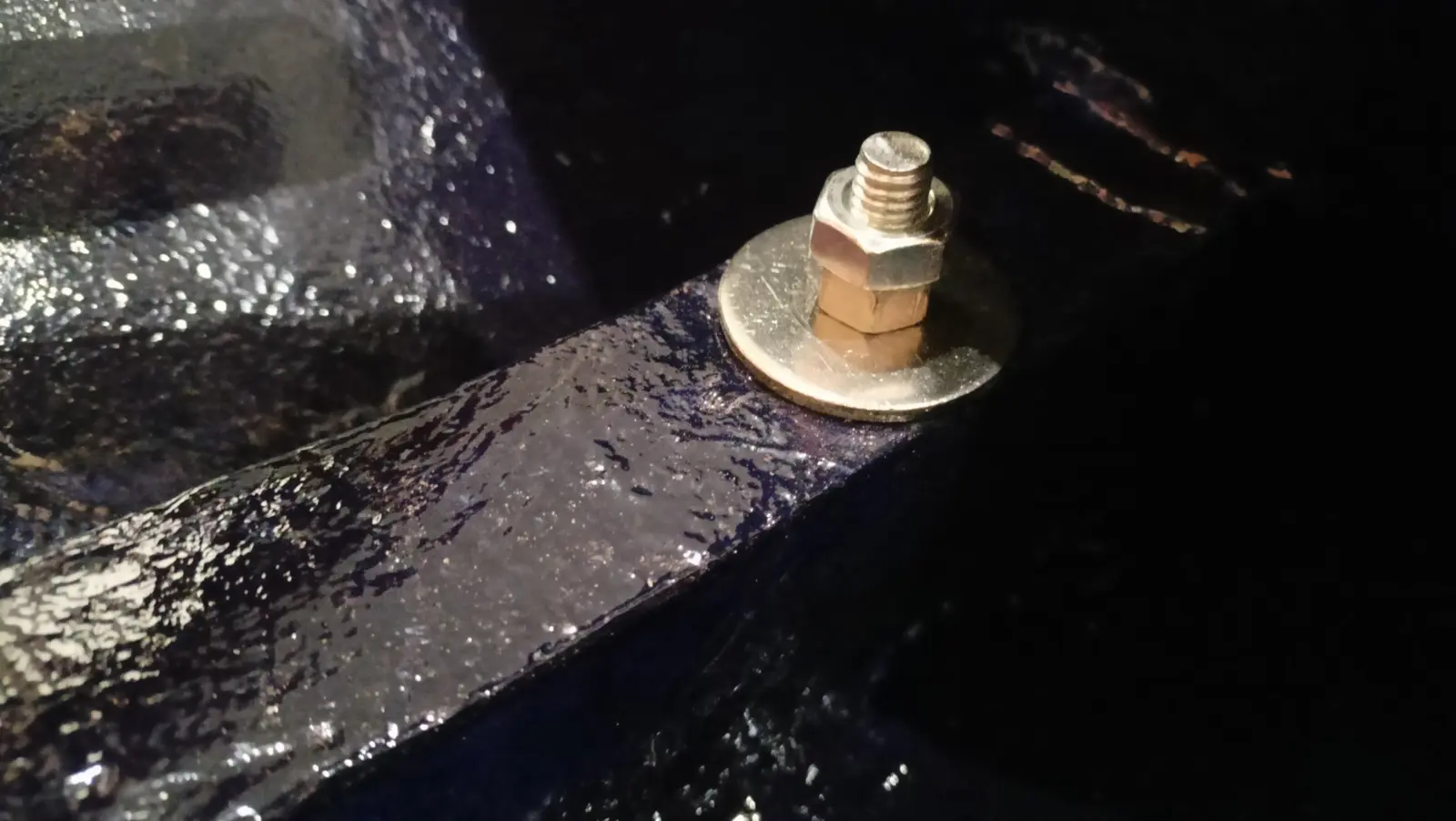
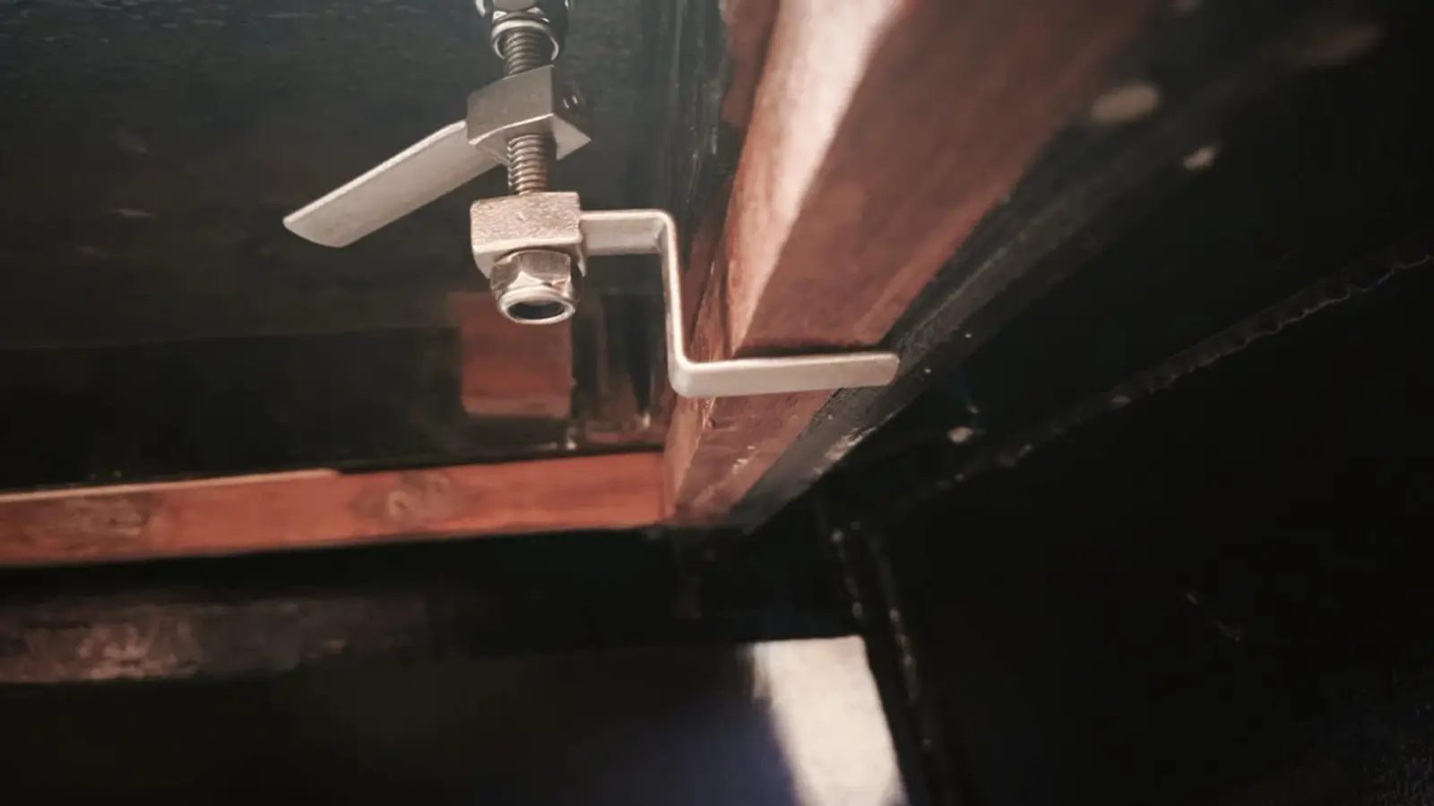
While the epoxy and the primer were drying I turned to fixing the seat to the boat's framework. Obviously I did not want to use wood screws, because I thought it would be good if the seat could come out, and wood screws would cause damage. So a hole was drilled, resin was put in it, and an insert for a bolt was fitted in the arrangement shown in the photograph. The washer holds the insert at the height I want, while the nuts set how far in the bolt goes. The whole assembly was sprayed with silicone spray so it would not stick to the resin. Five hours later the bolt, washer and nuts were removed and the insert was left in. The next day, once the resin had gone very hard, I took that out as well. That way a thread was formed for the insert, in case I ever want to take it out. Most likely it will never be needed, since it is stainless steel, but it is good to have the option.

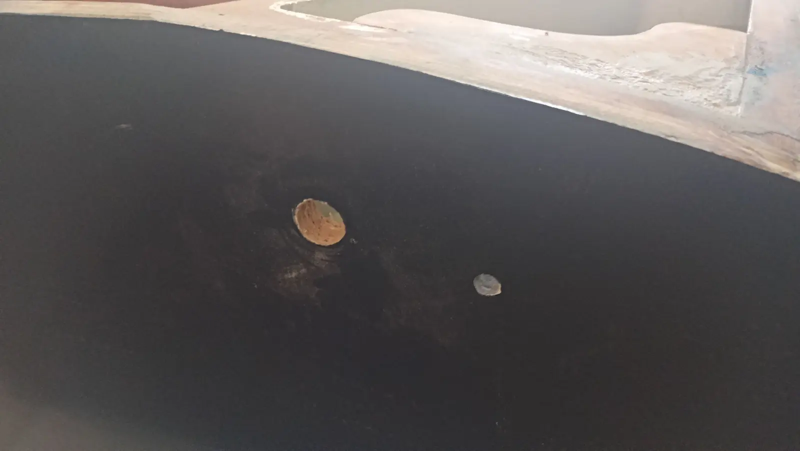
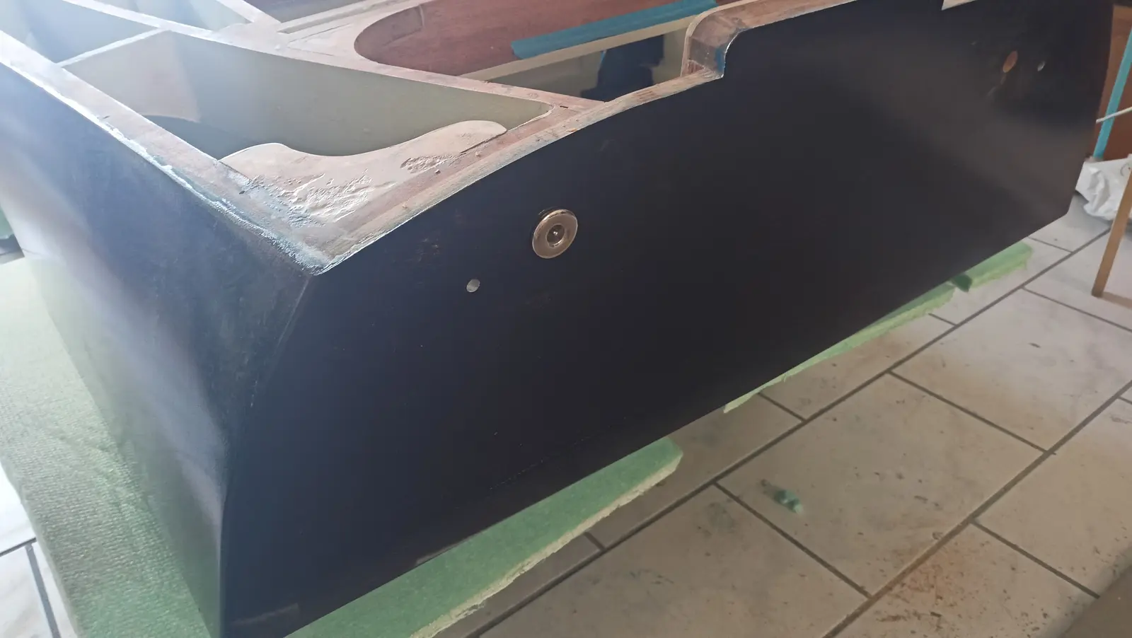
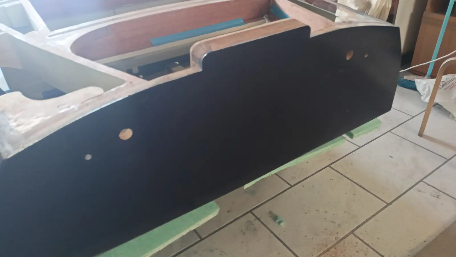
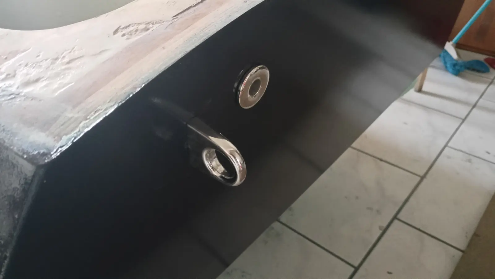
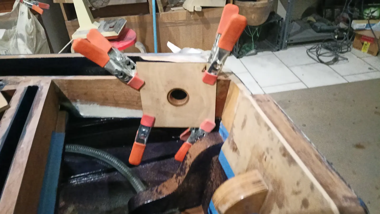
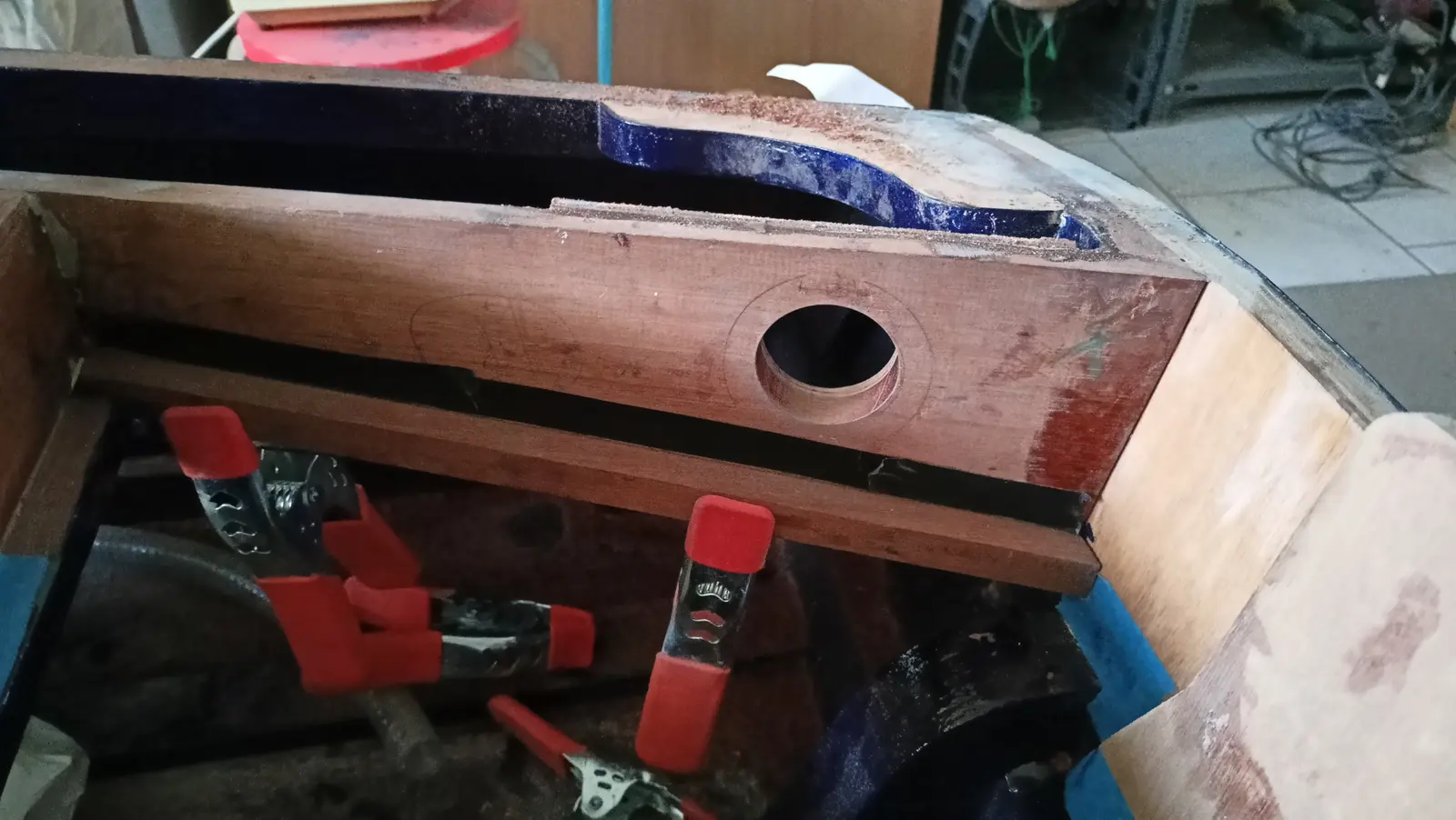
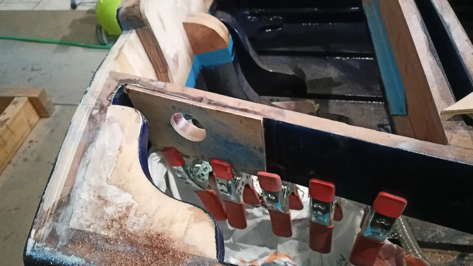
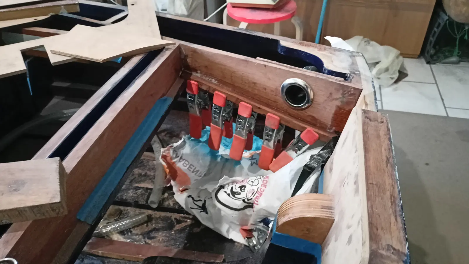
Holes were also drilled for the pump outlets and for the stainless fittings. They were coated with epoxy and primer and will then get the polyurethane paint as well.

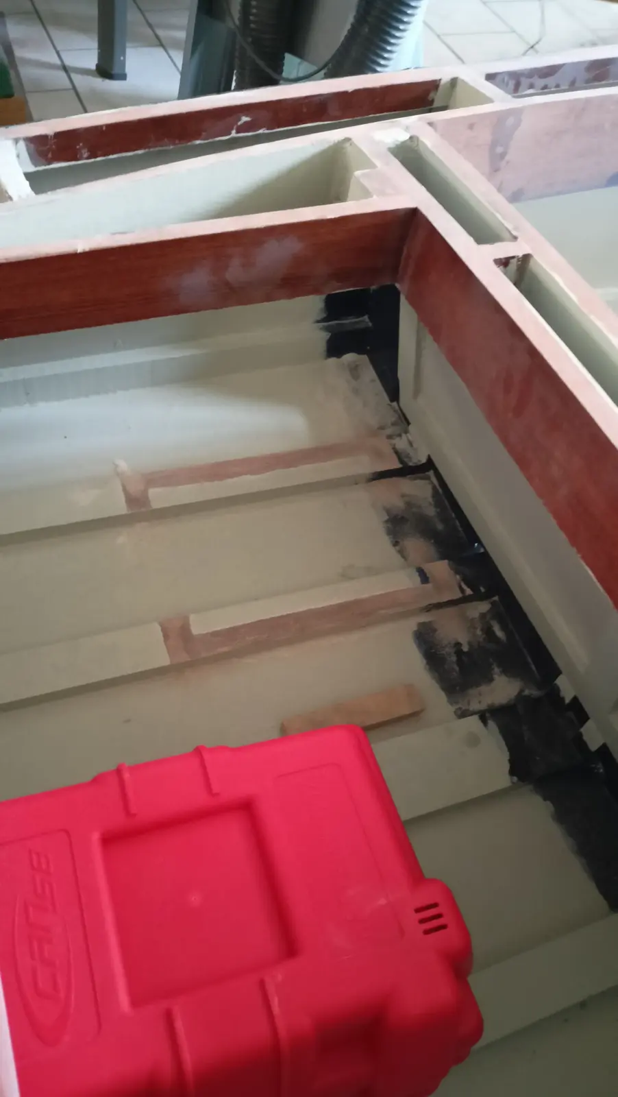
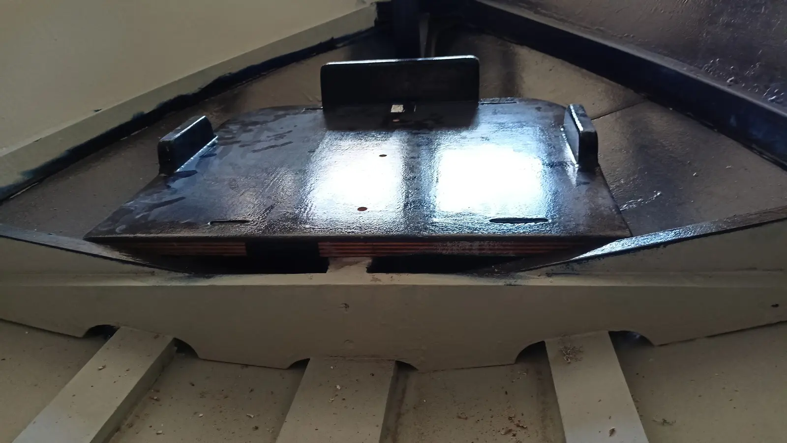
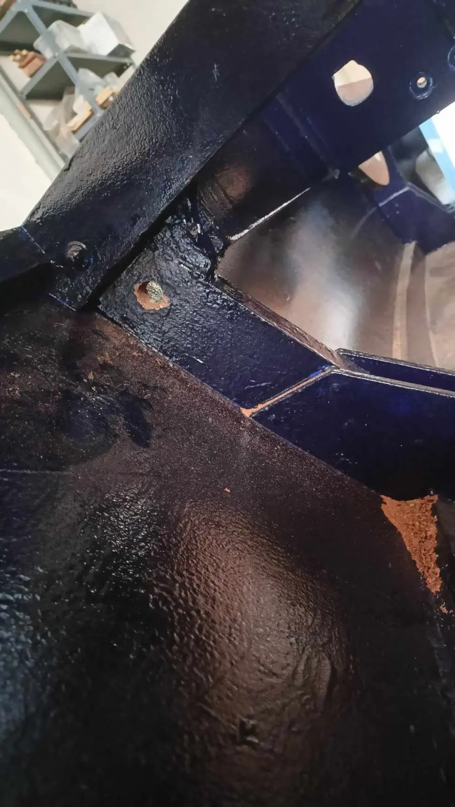
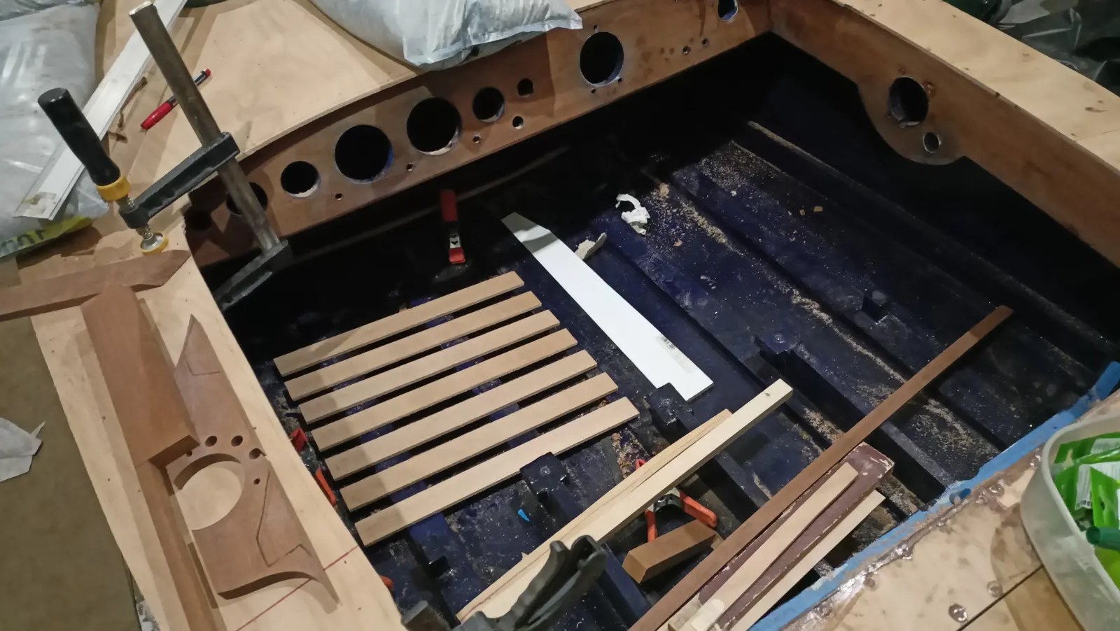
Before gluing the tank base and the battery box, the area I would have no access to after gluing had to be painted. That was the underside of the base and the hull, and the bottom and back of the box. Obviously the areas to be glued were not painted.

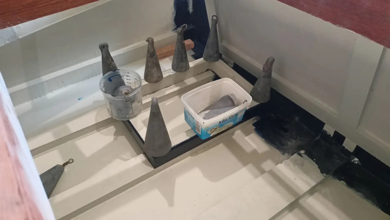
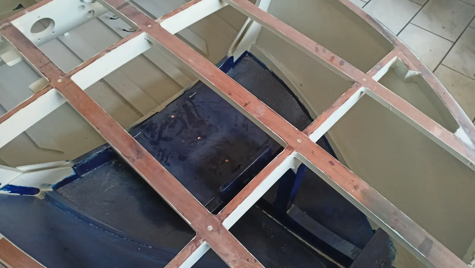
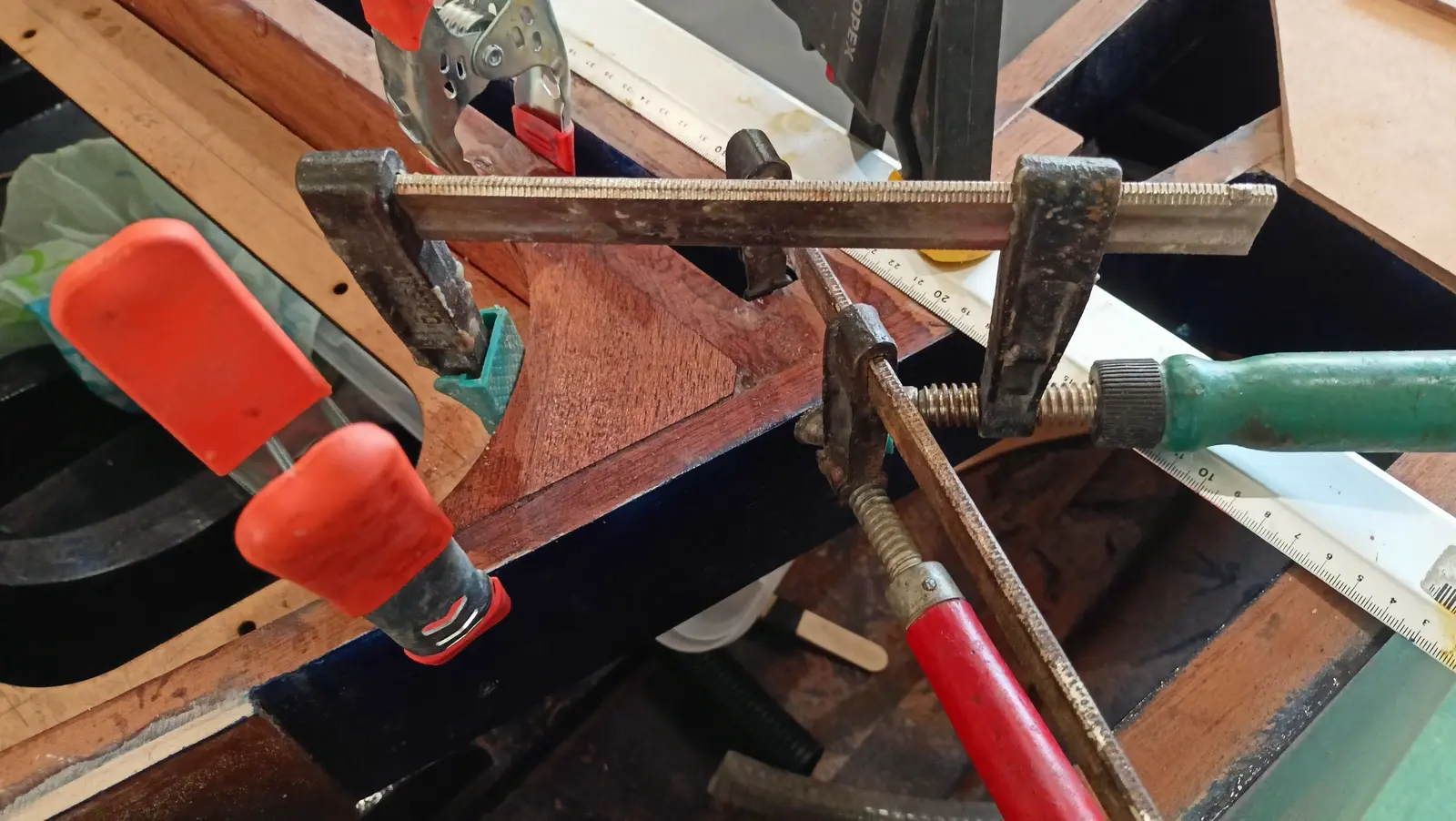
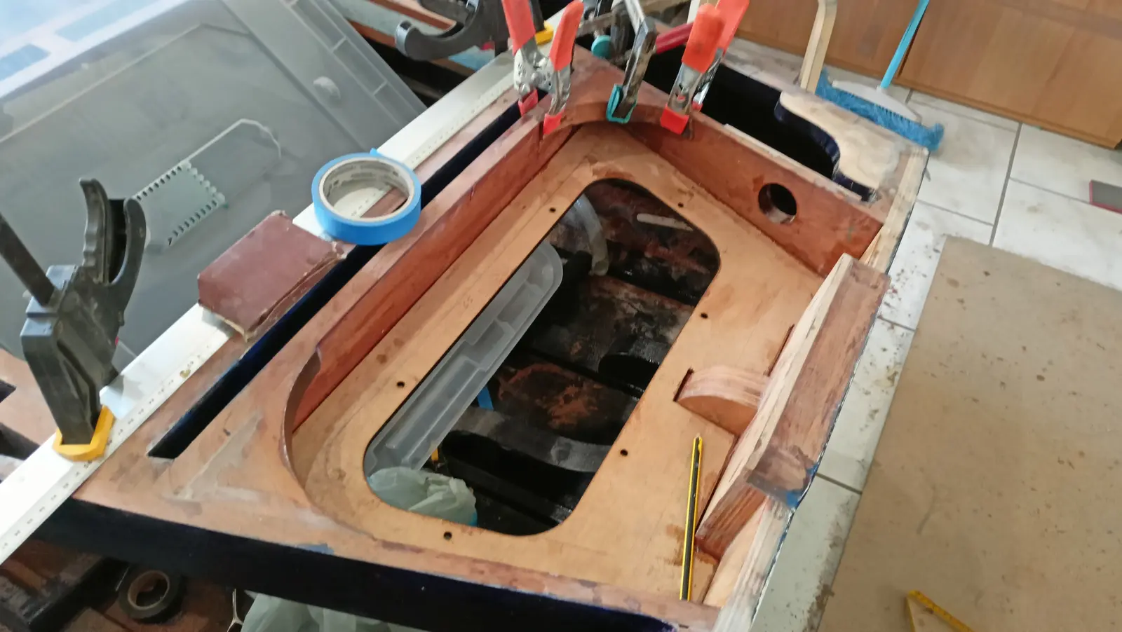
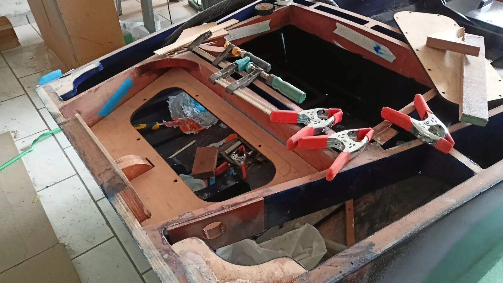
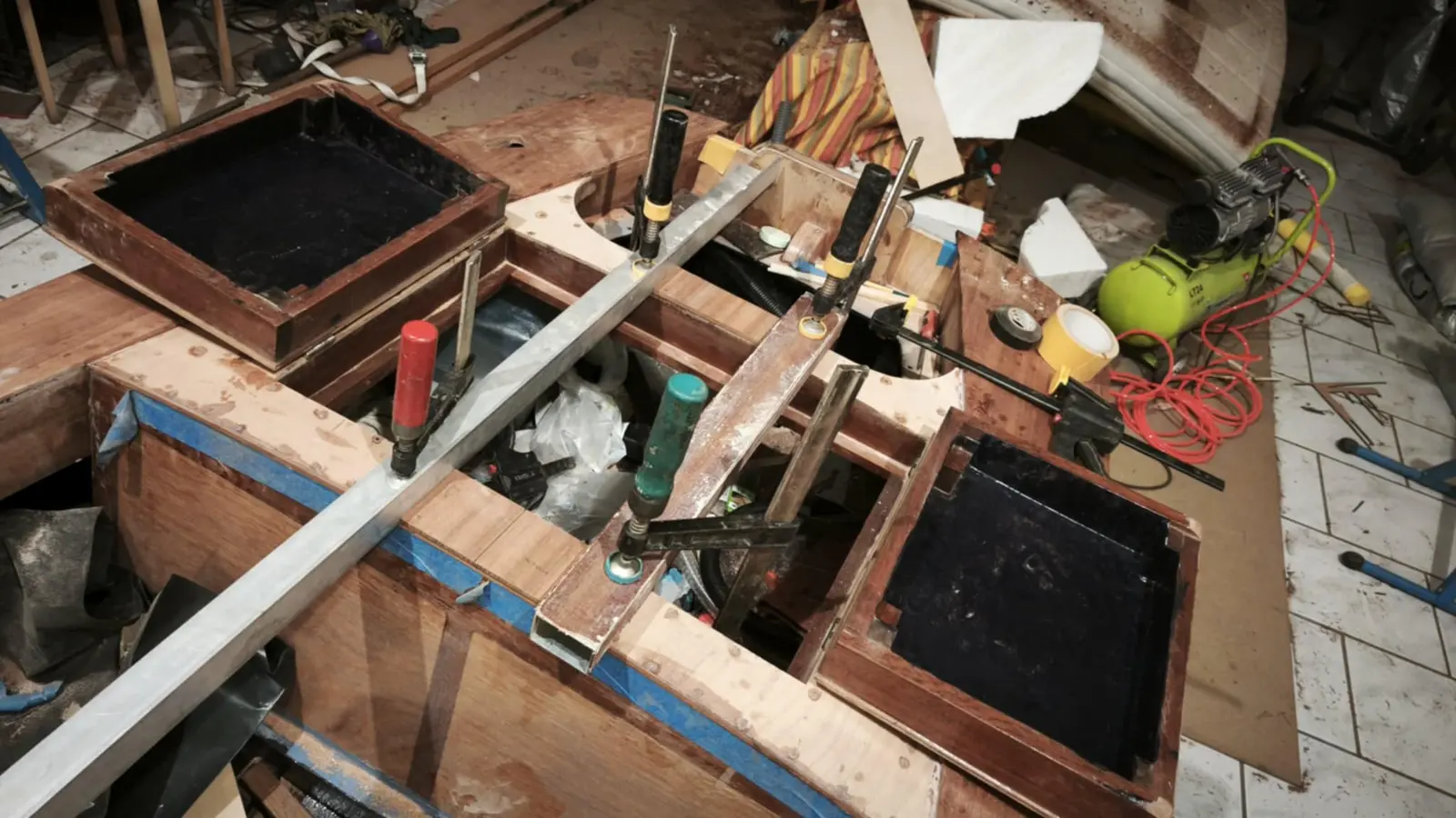
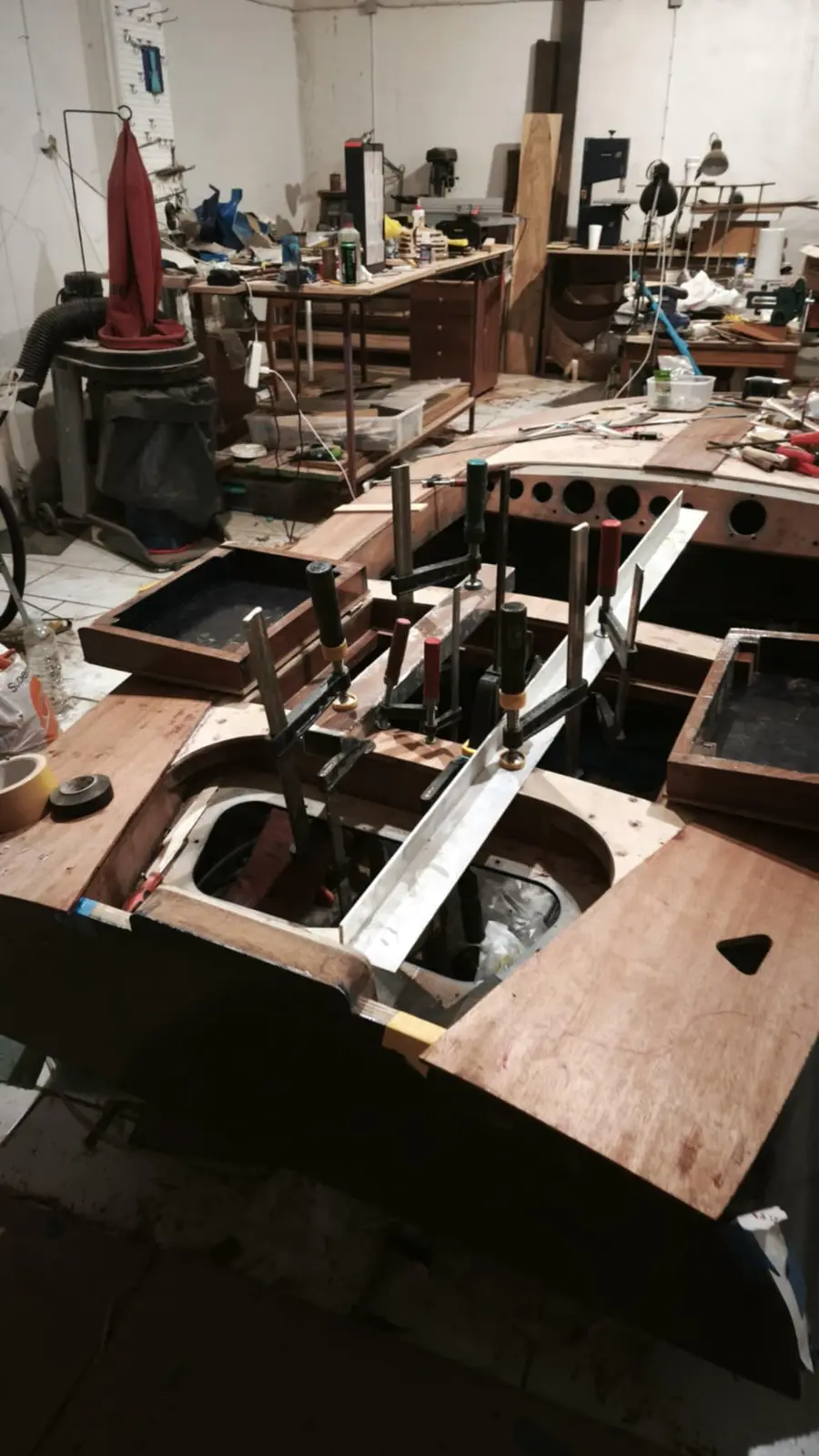
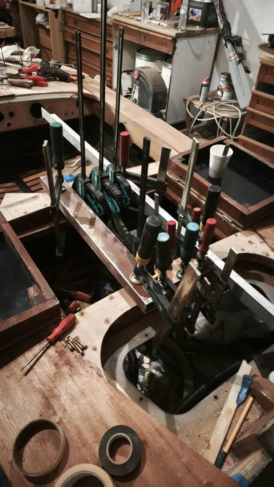
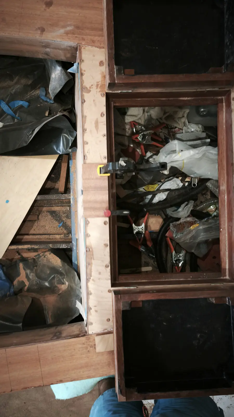
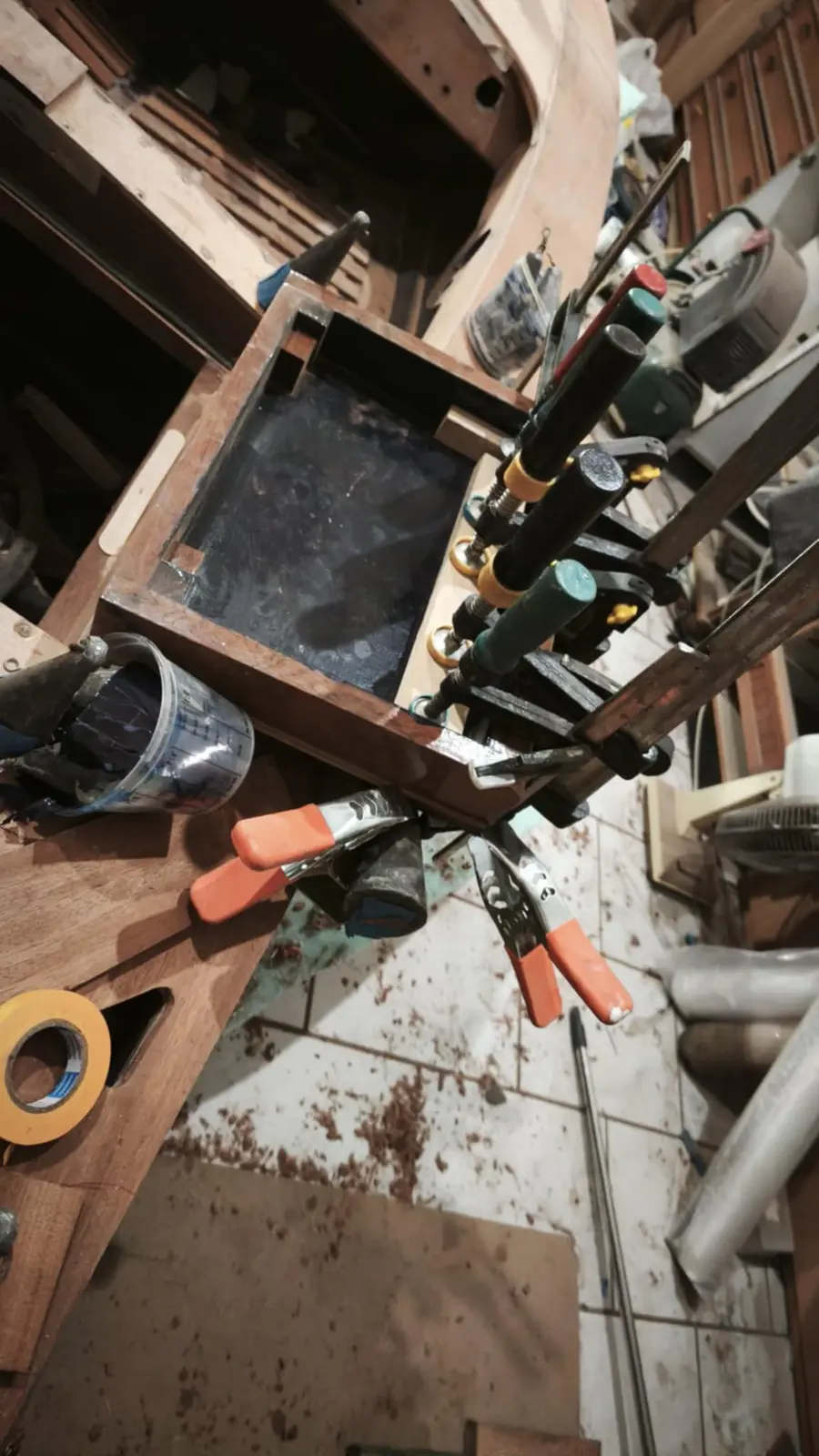
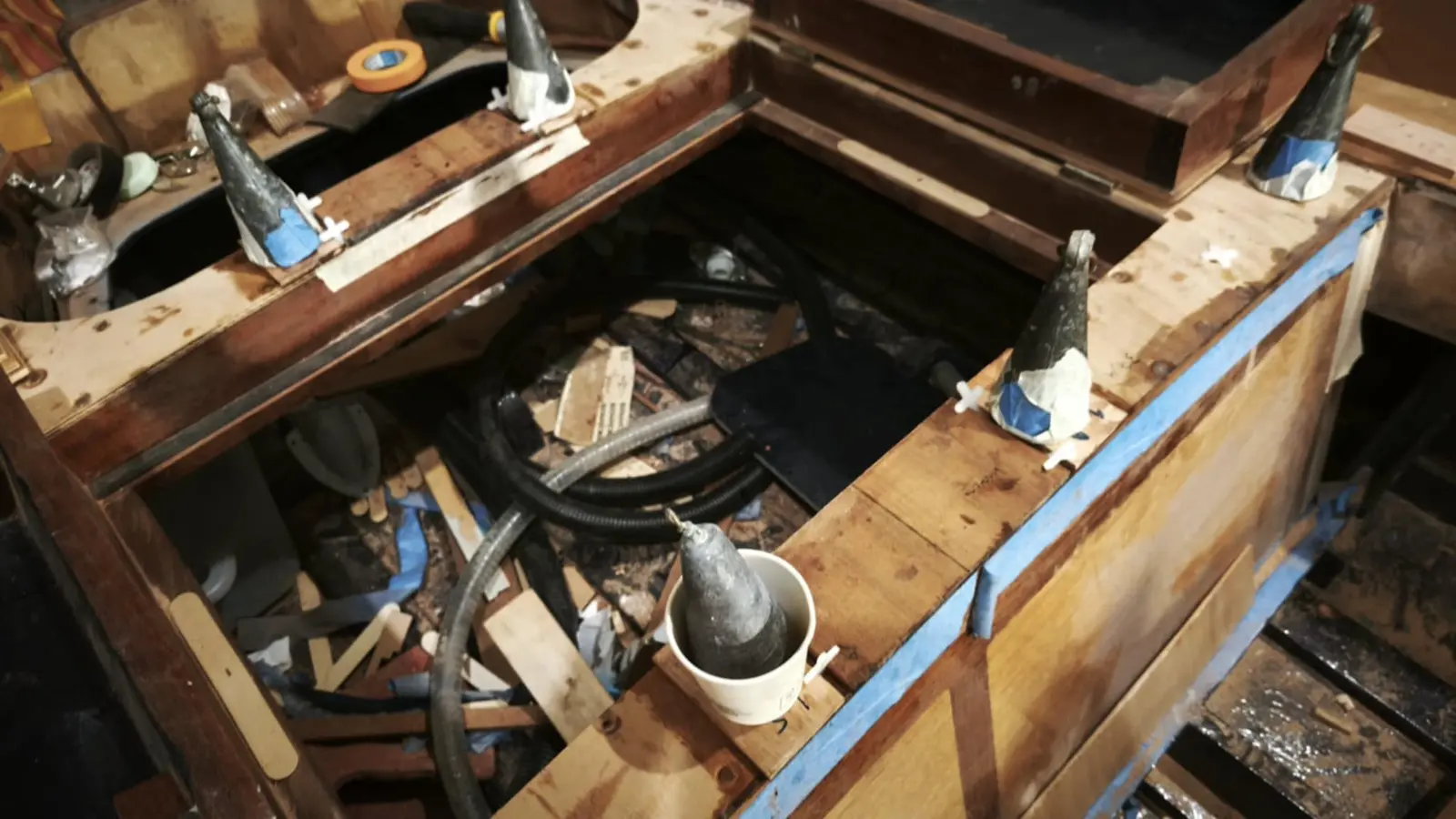
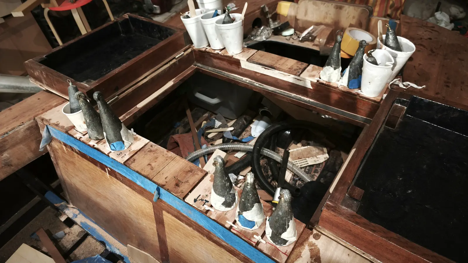
The battery box base was then glued in, in the way shown in the photographs.

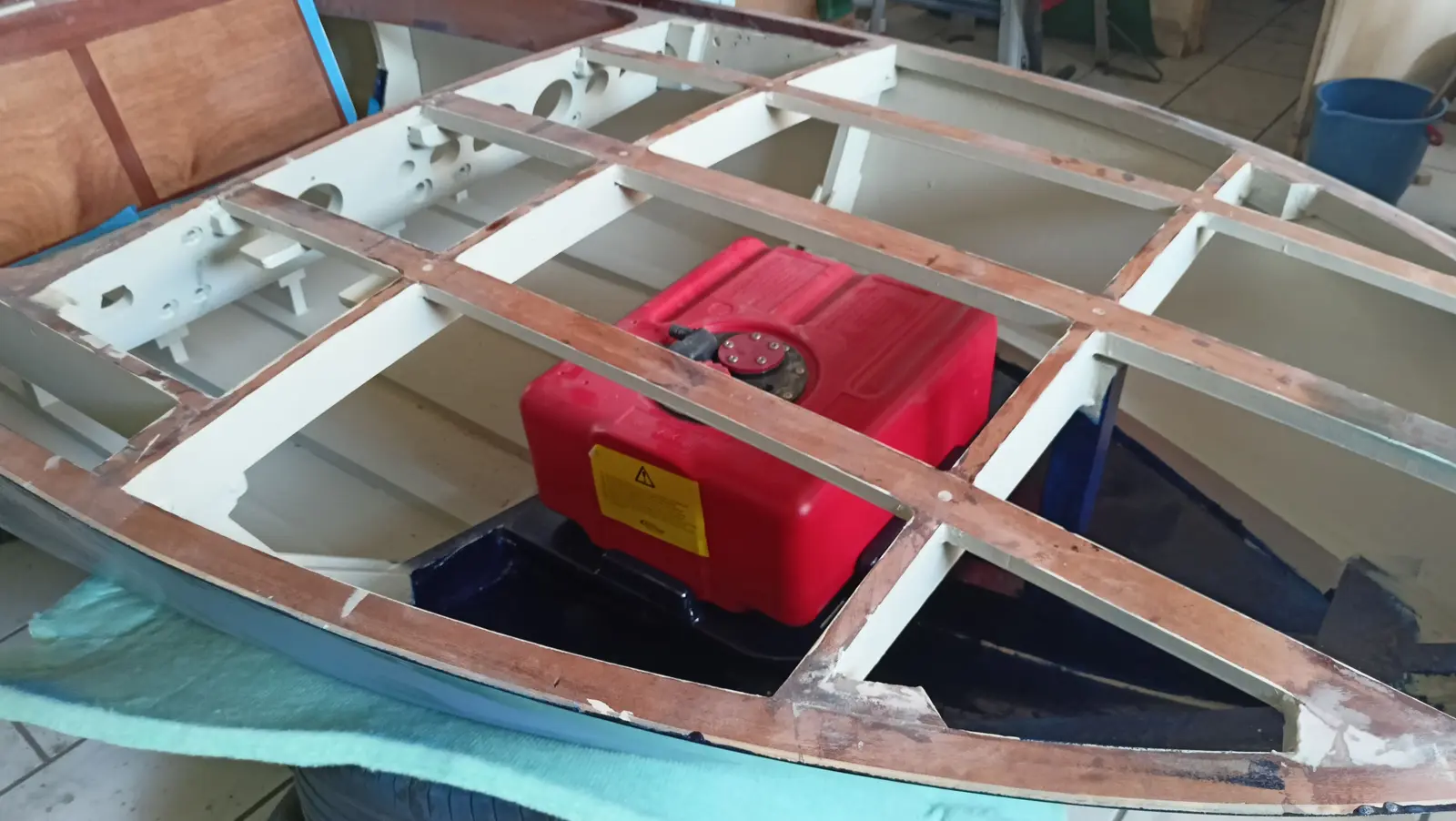
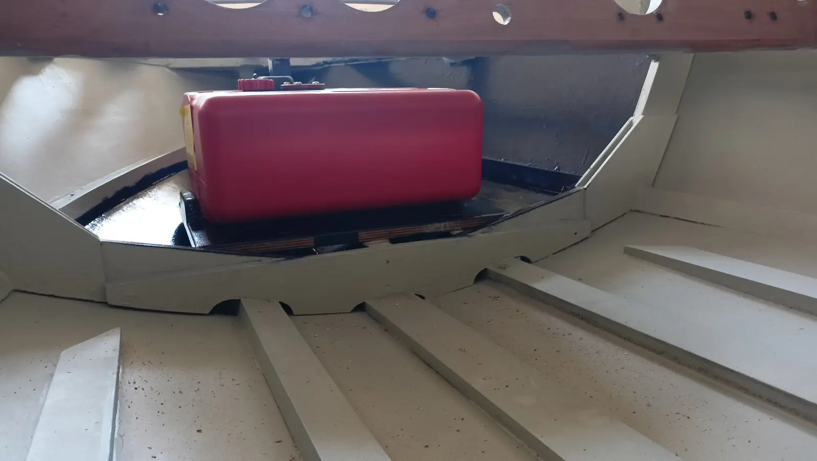
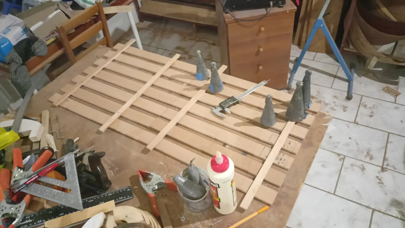
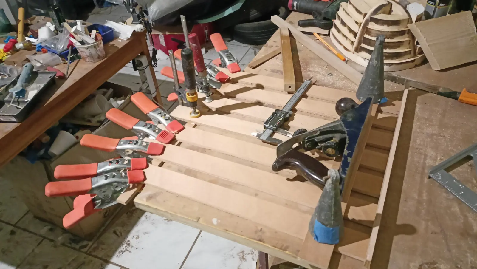
The next job was gluing the tank base.

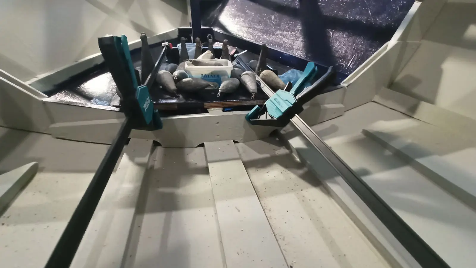
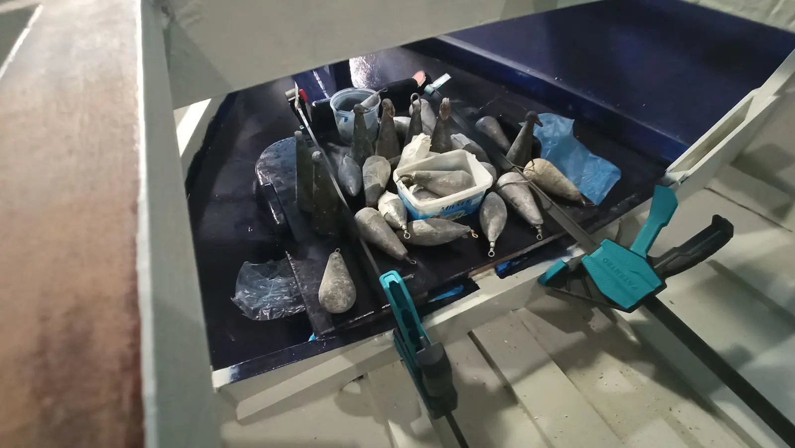
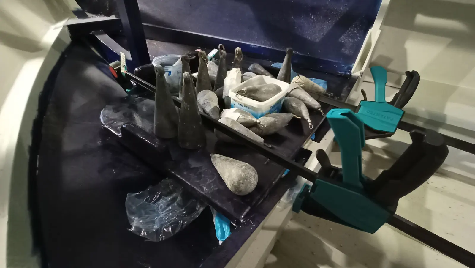
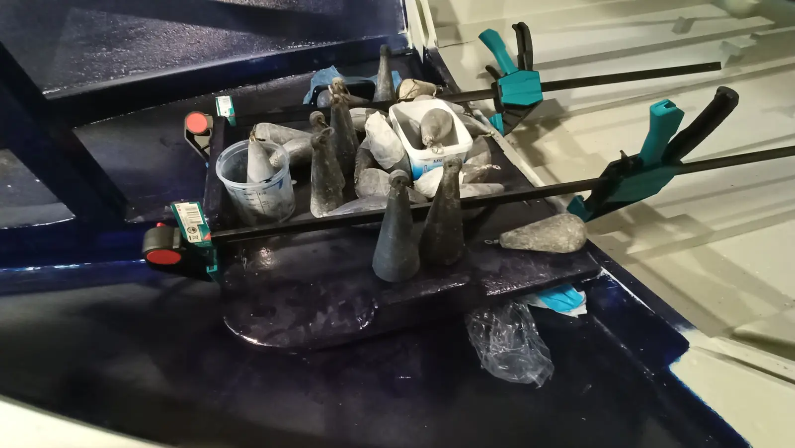
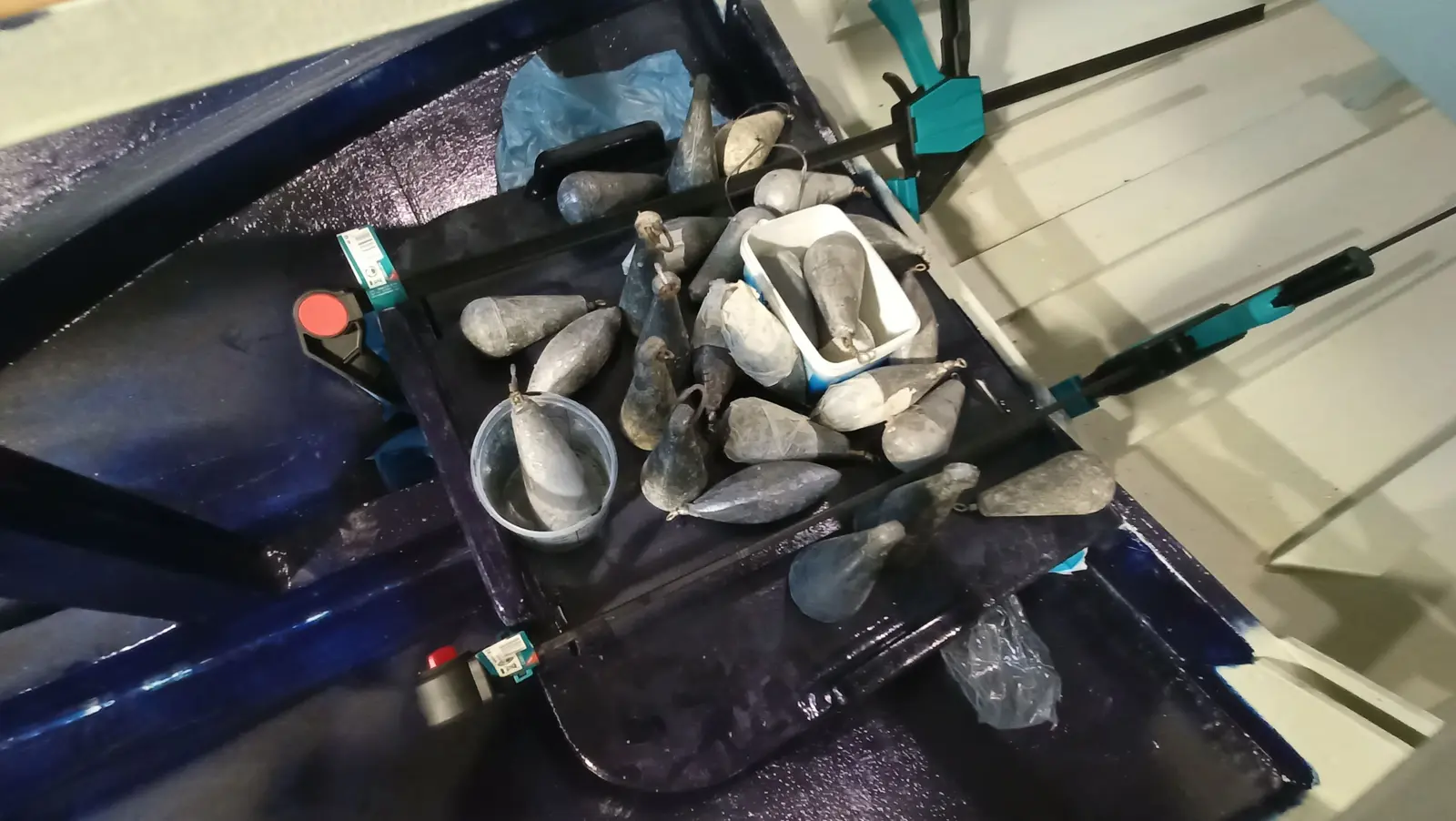
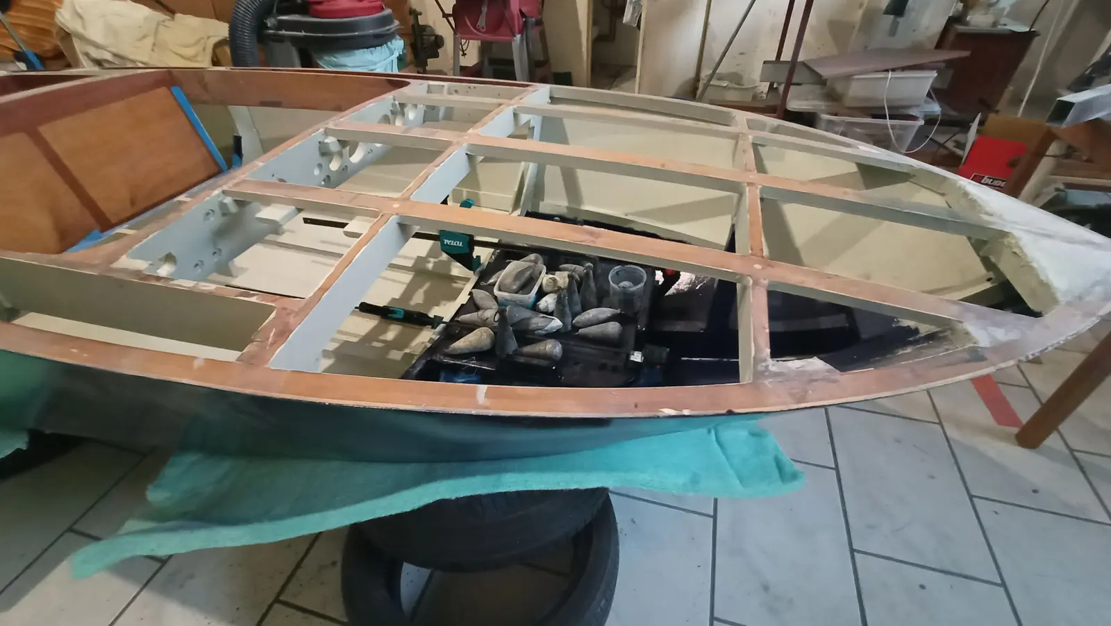
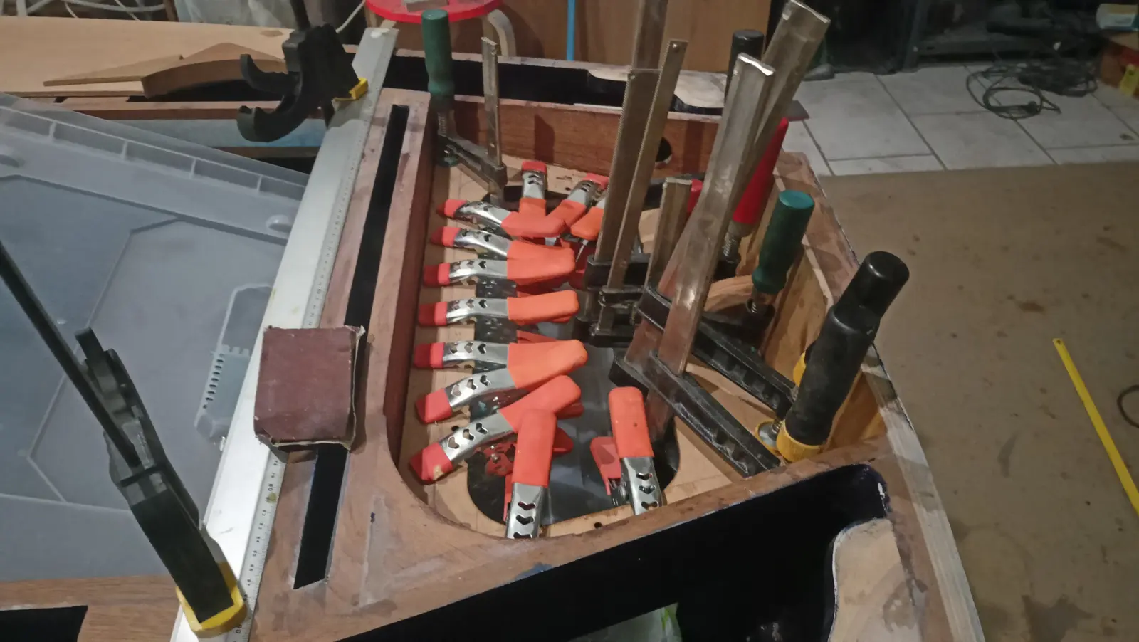
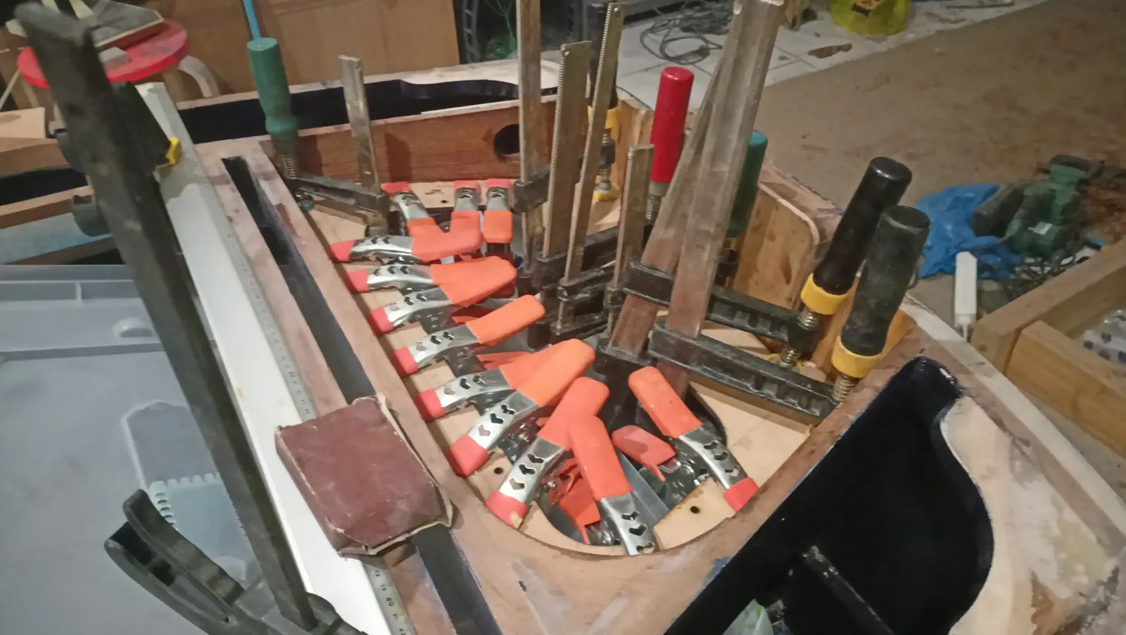
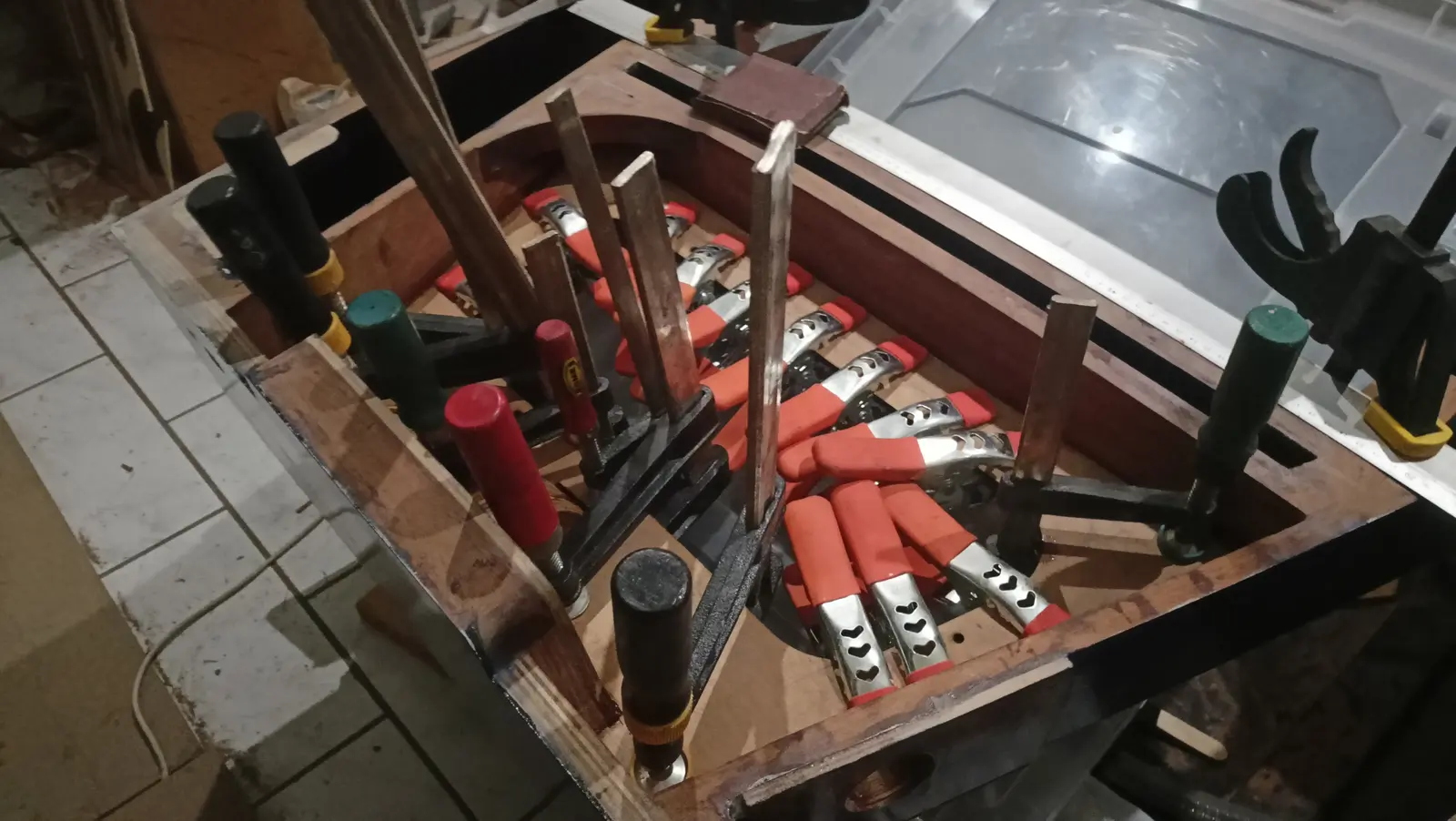
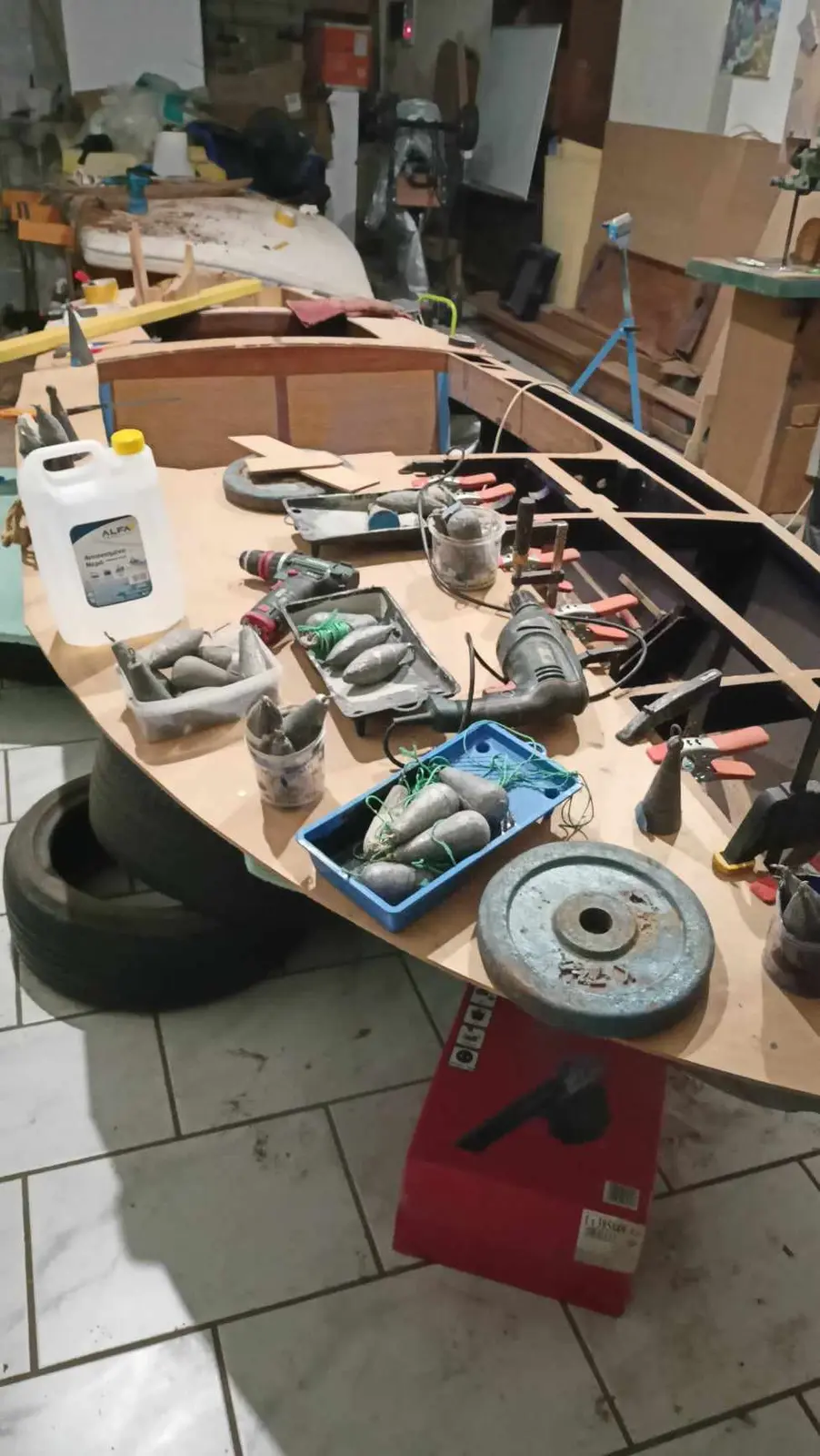
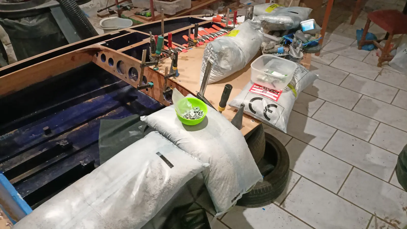
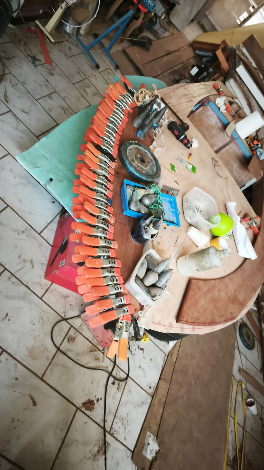
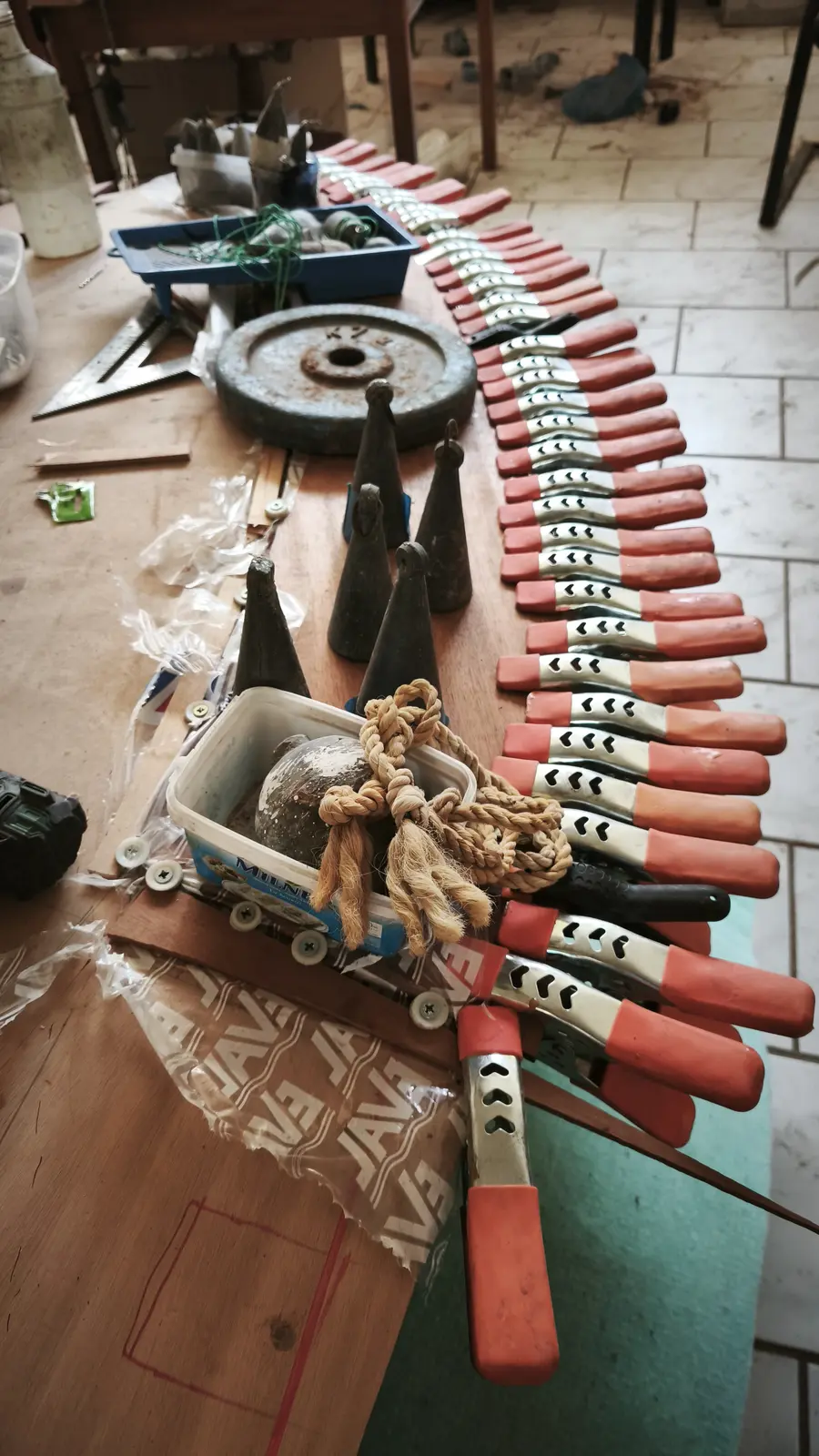
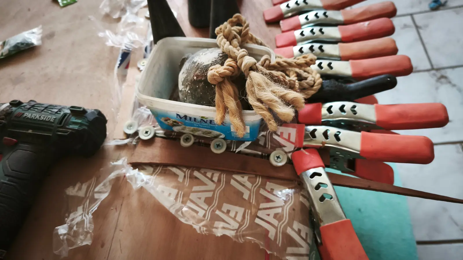
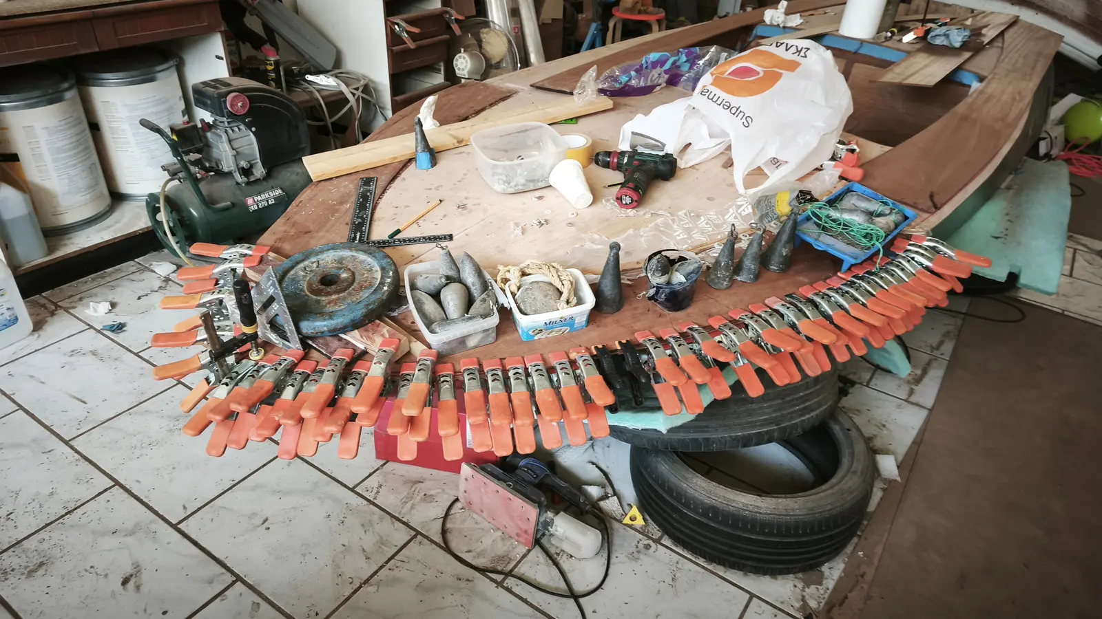
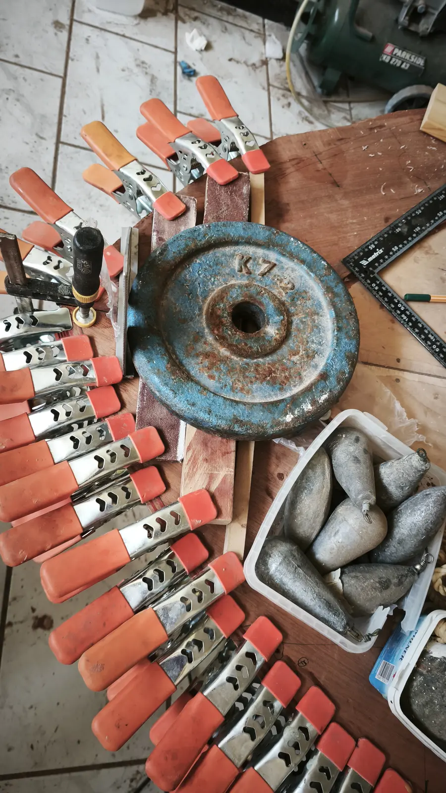
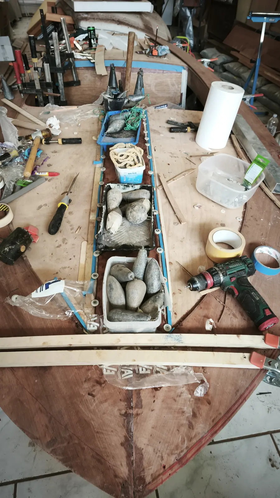
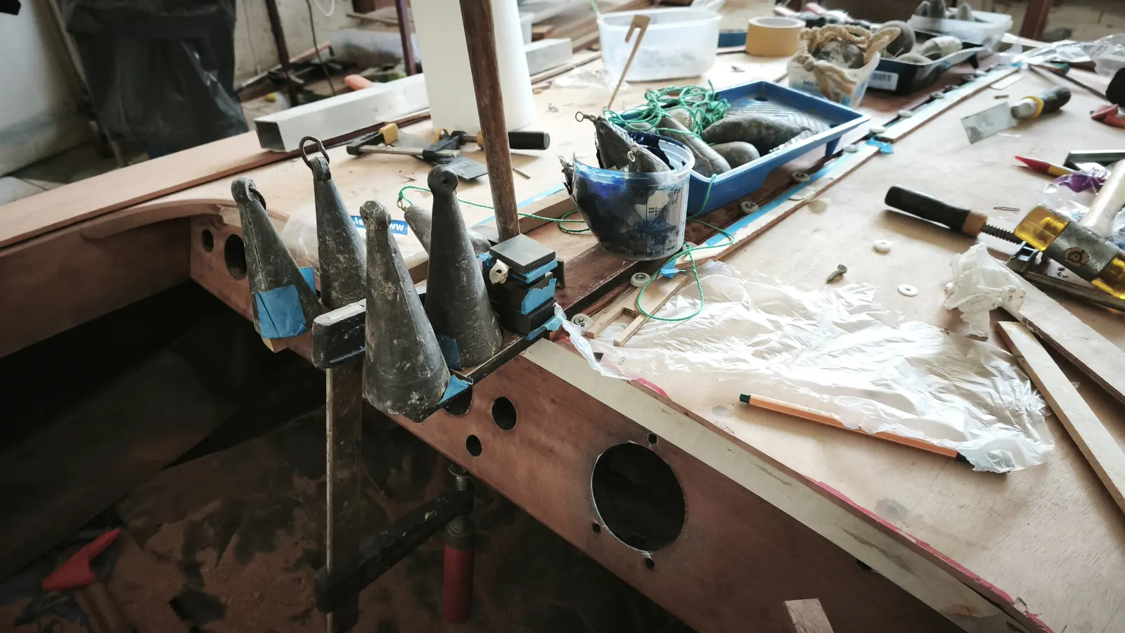
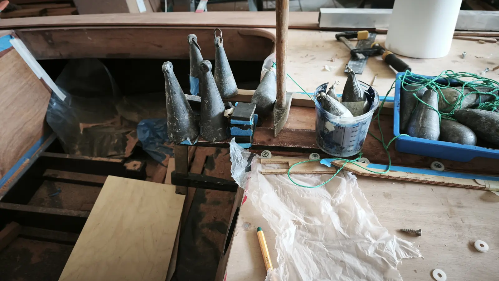
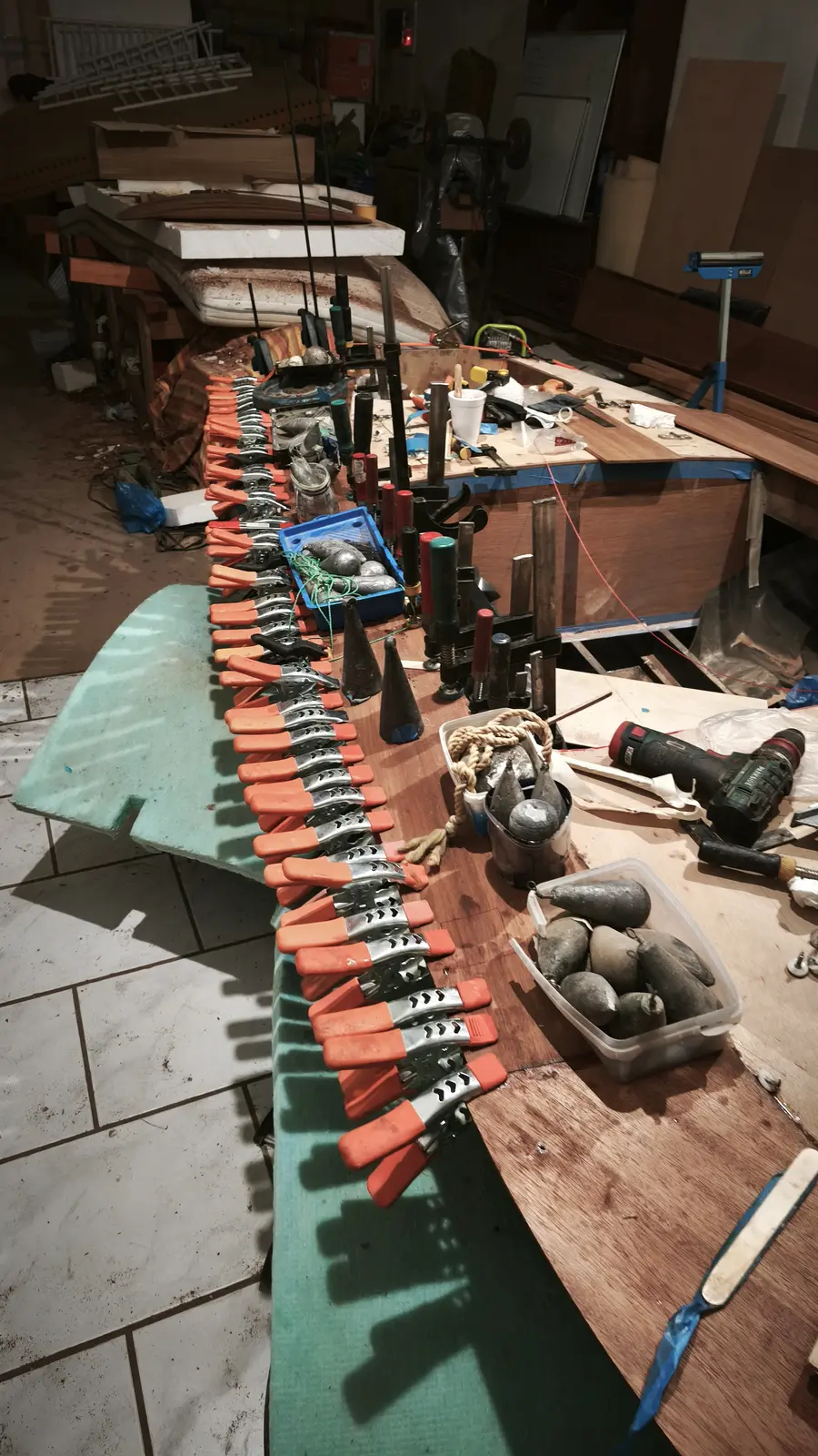
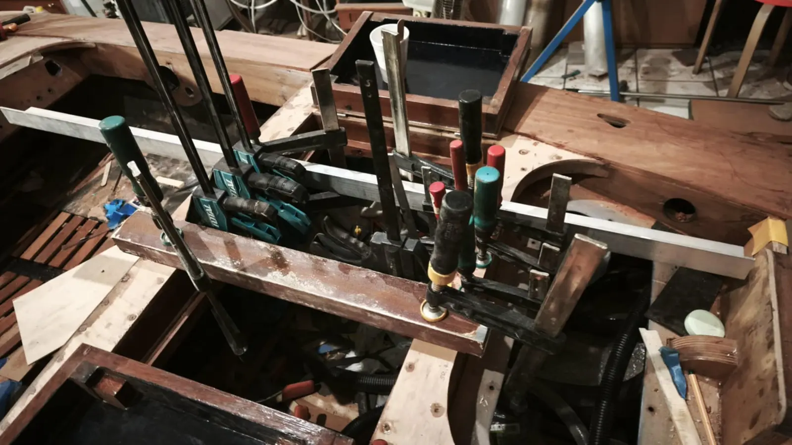
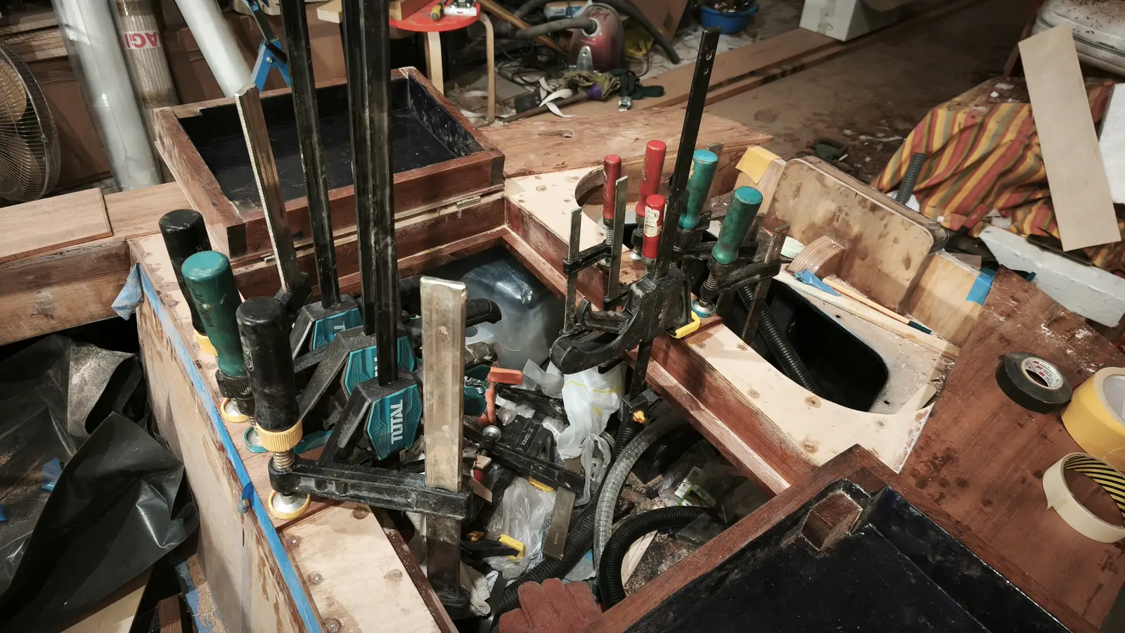
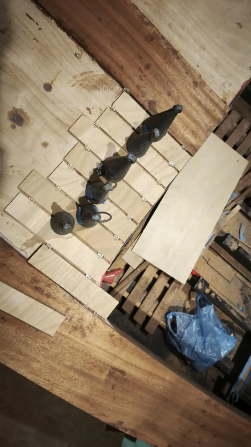
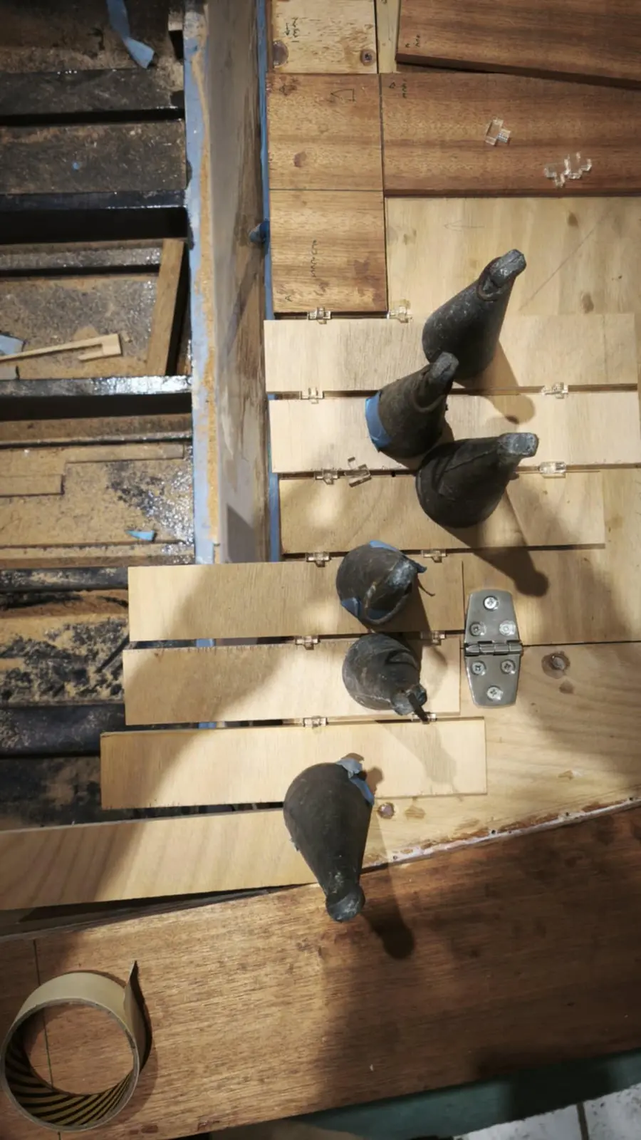
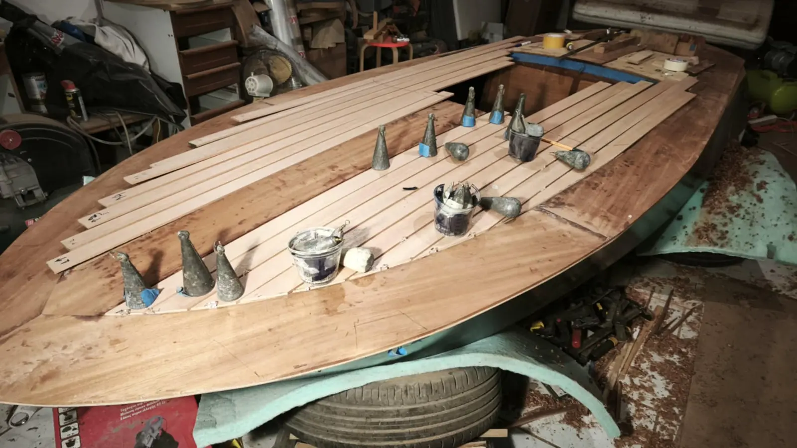
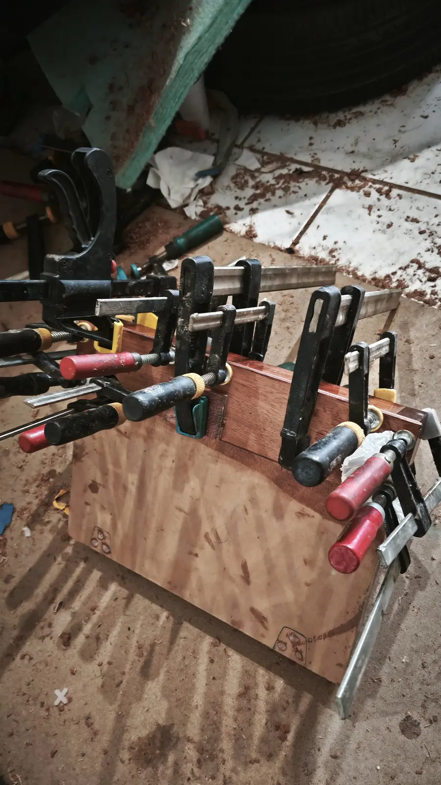
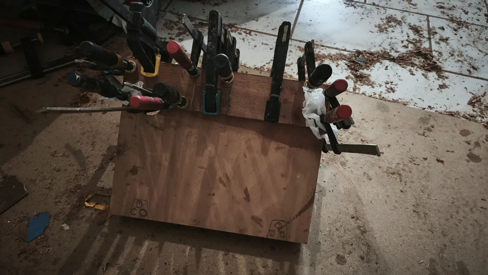
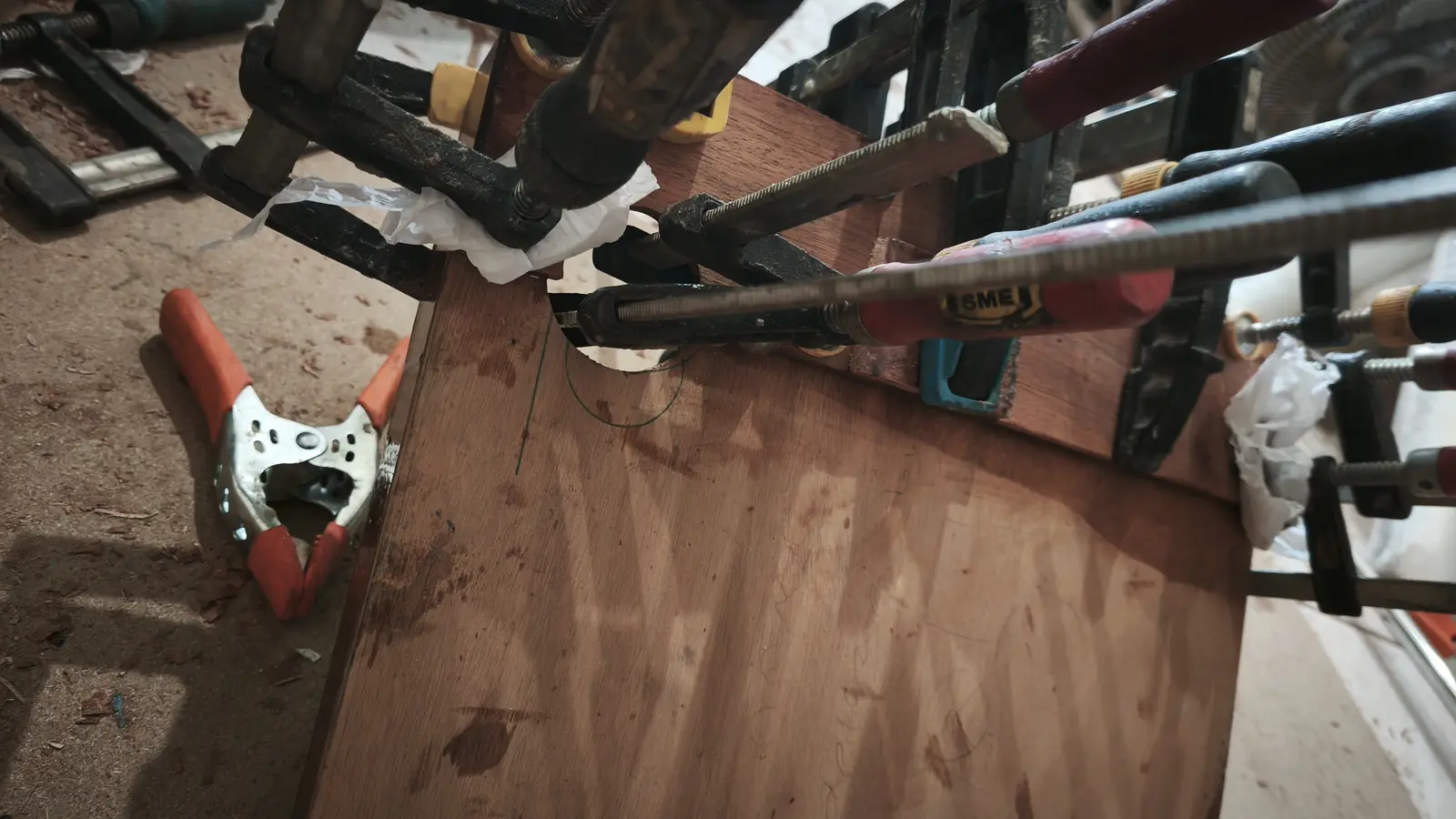
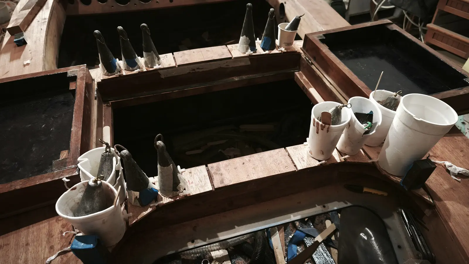
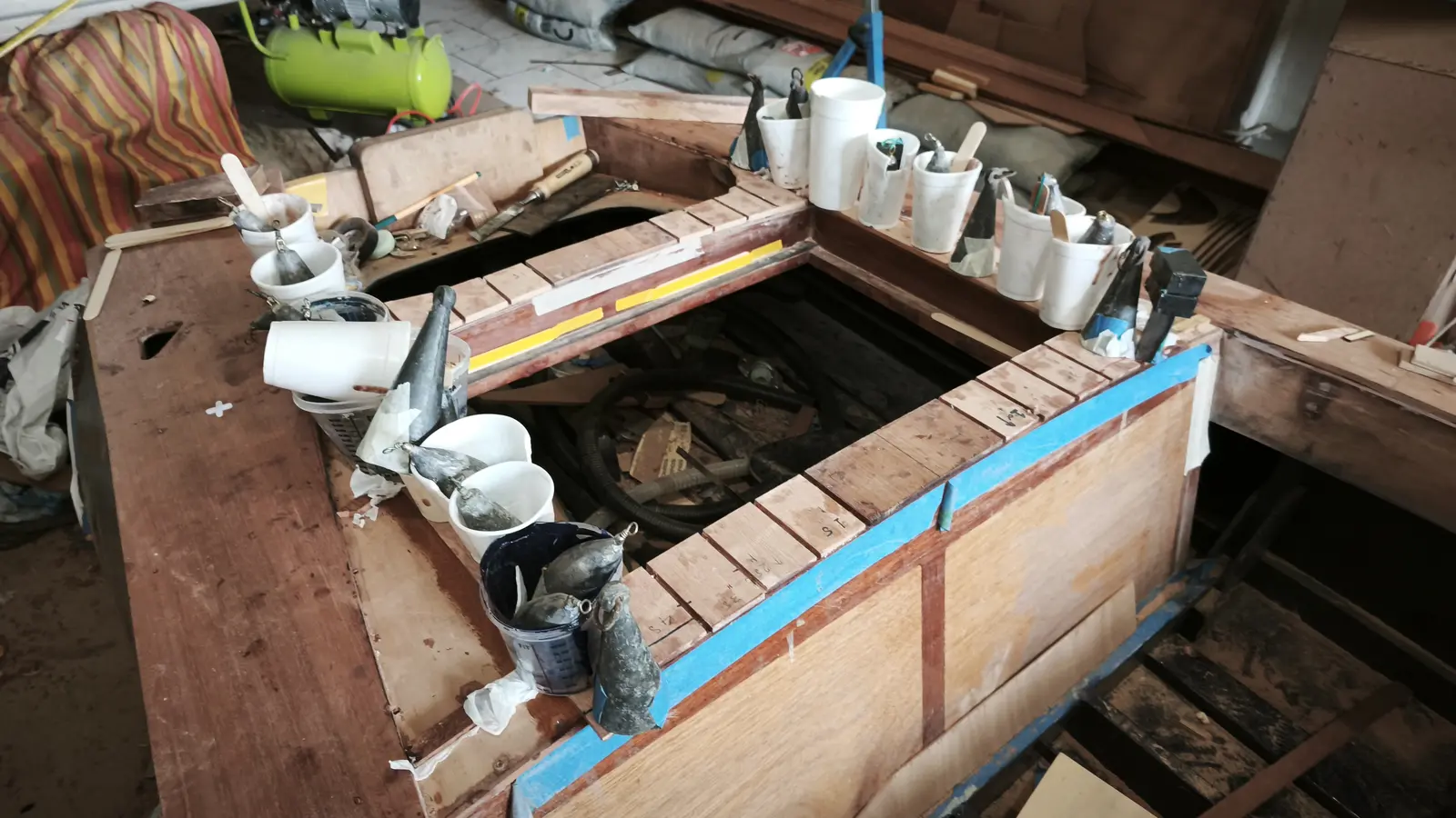
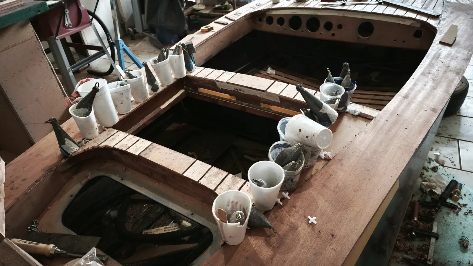
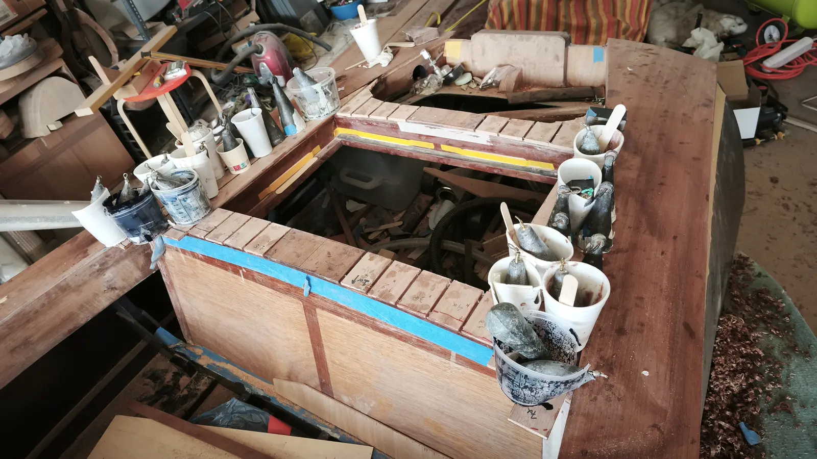
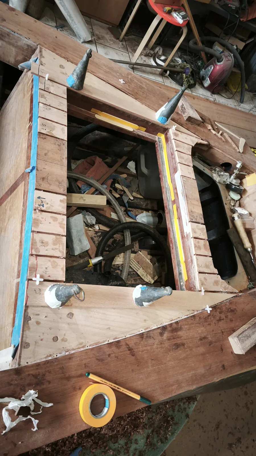
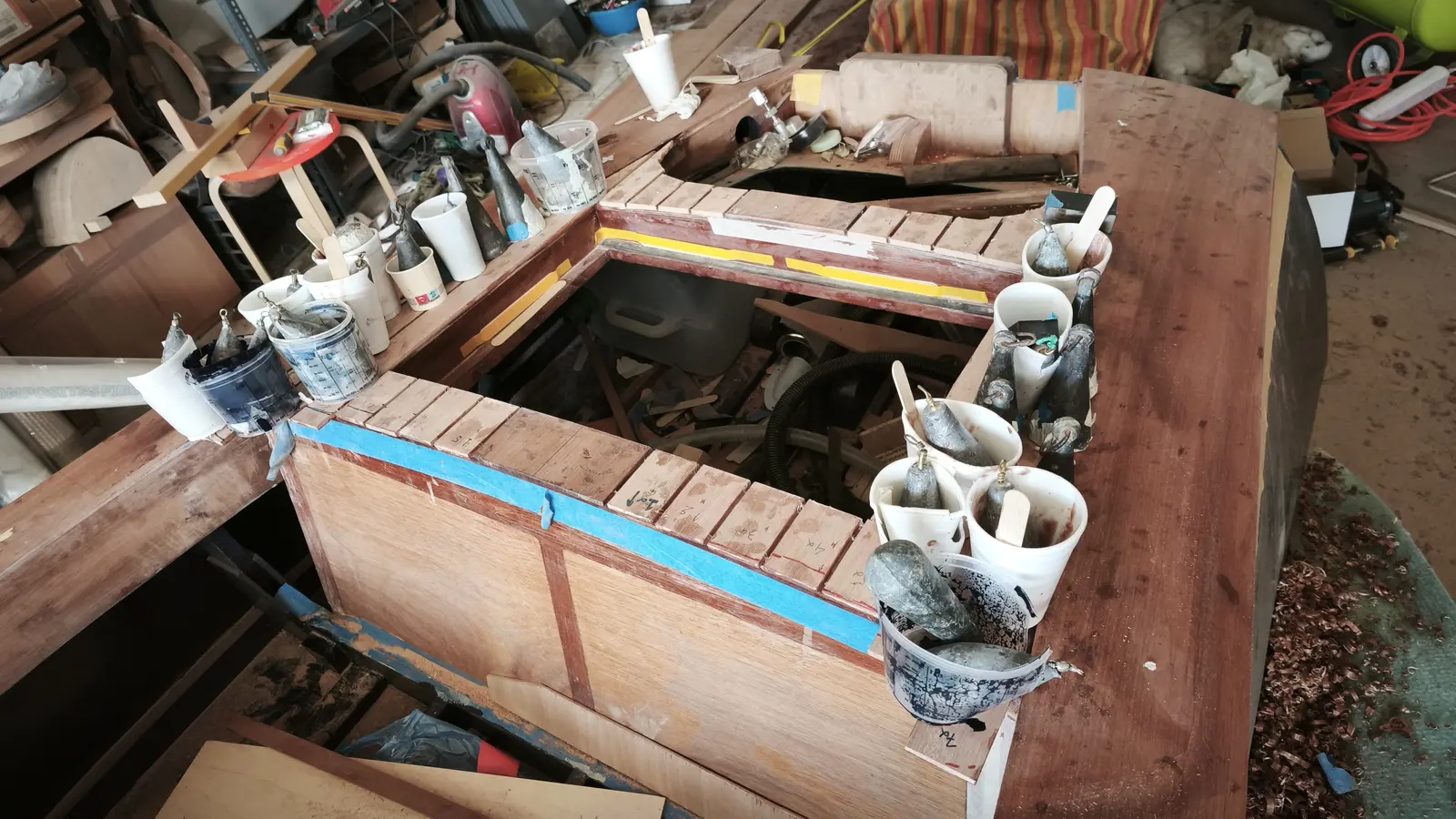
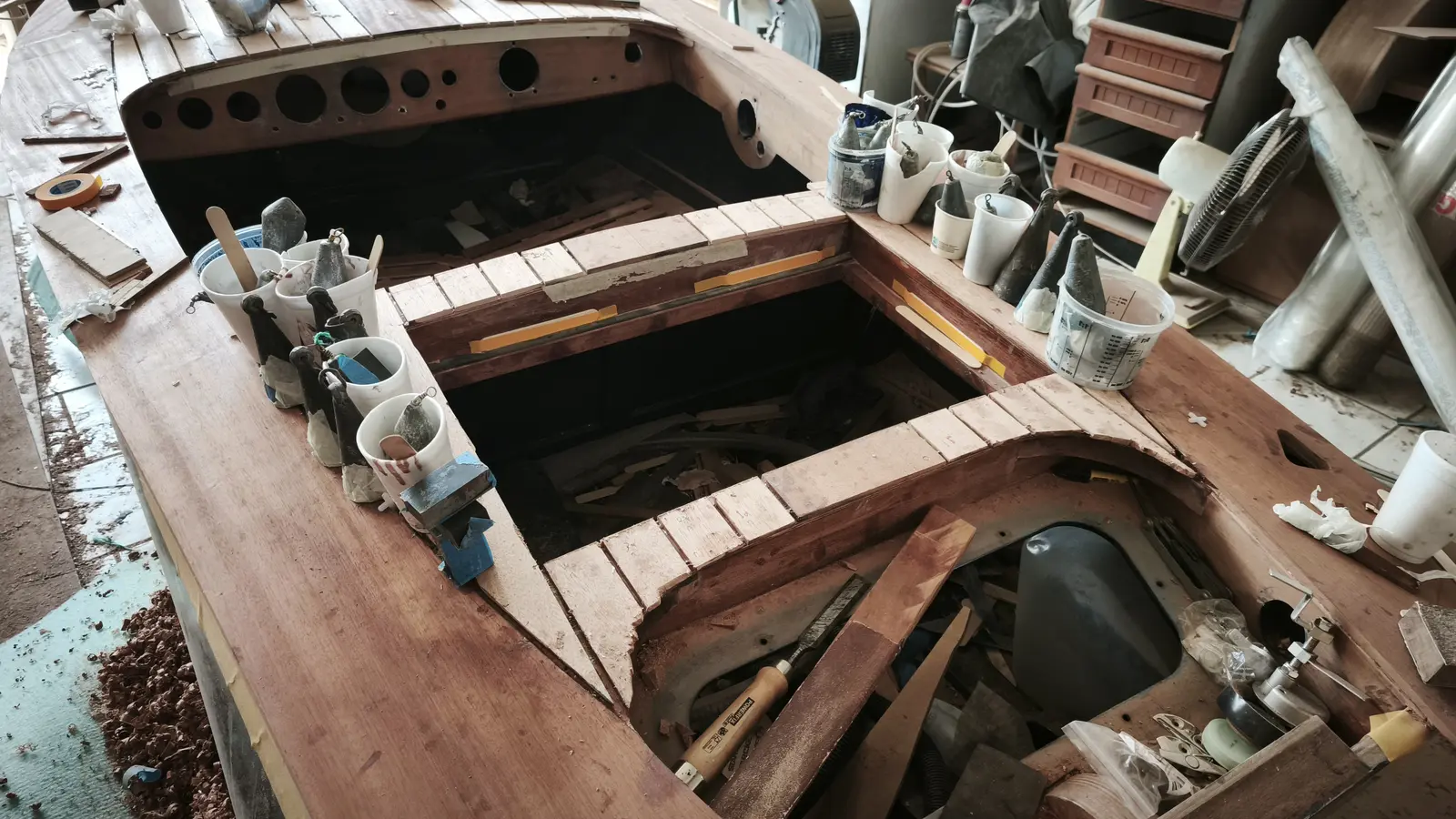
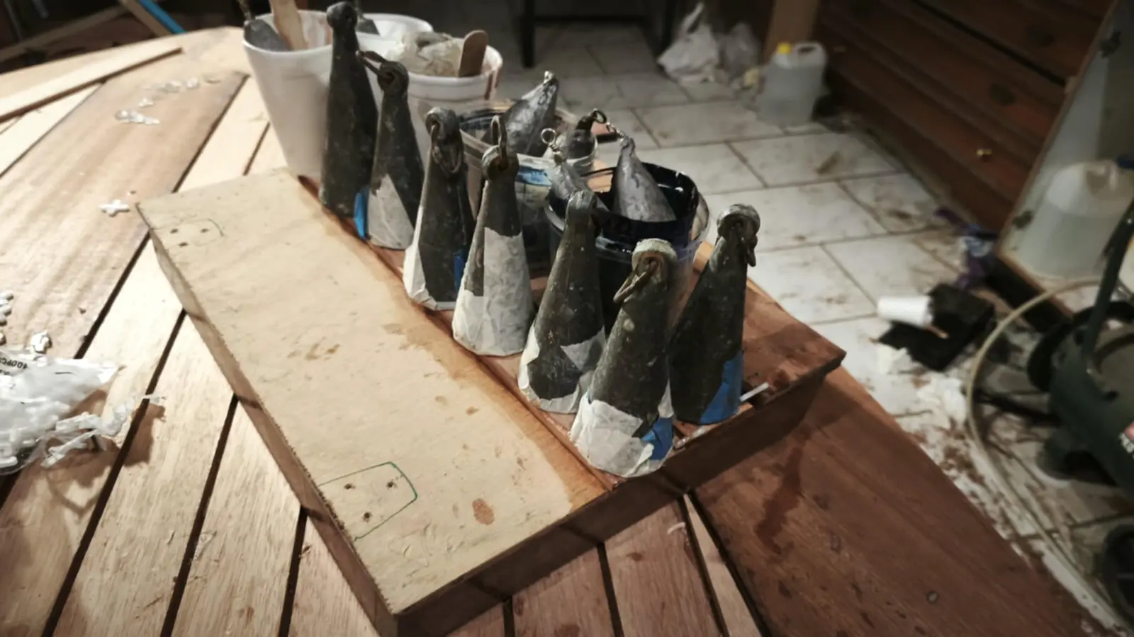
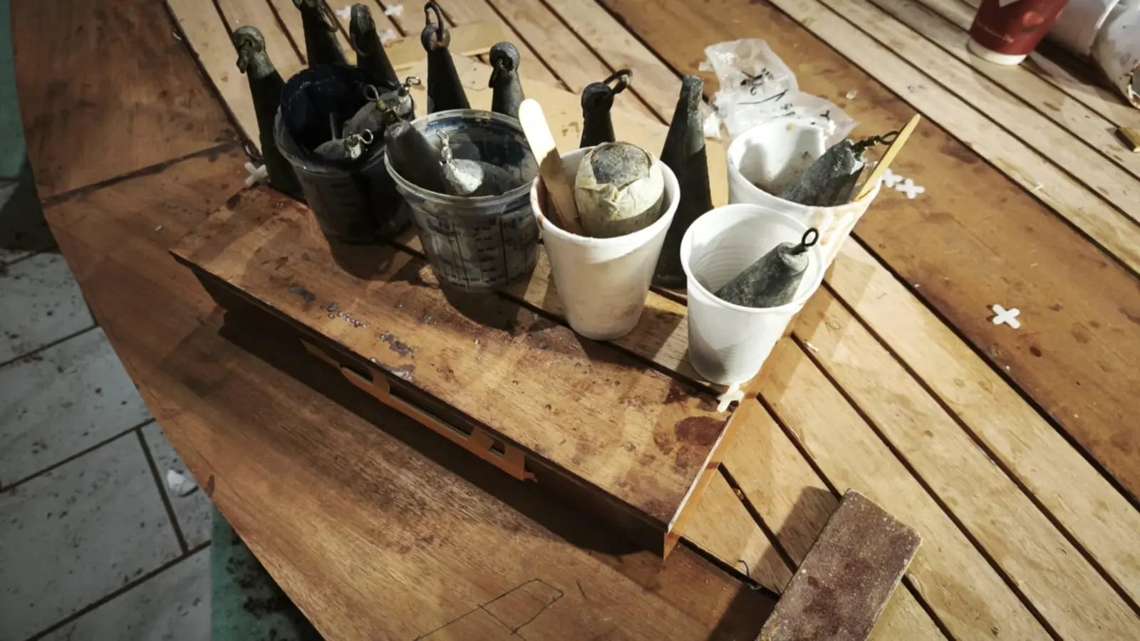
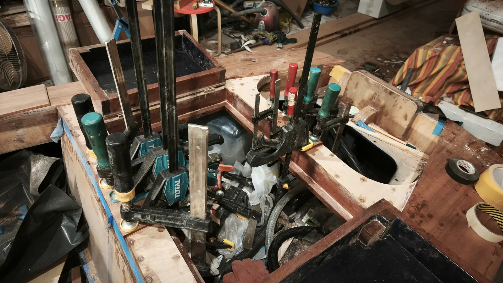
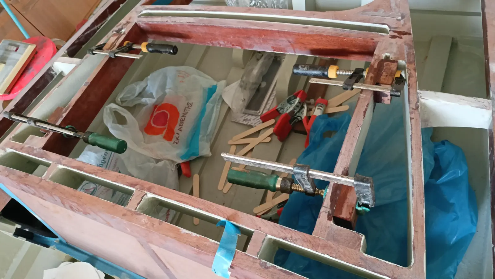
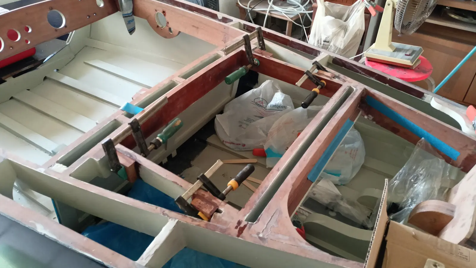
Large clamps were bought and fishing weights were used for pressure.

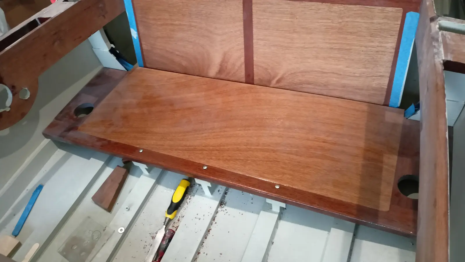
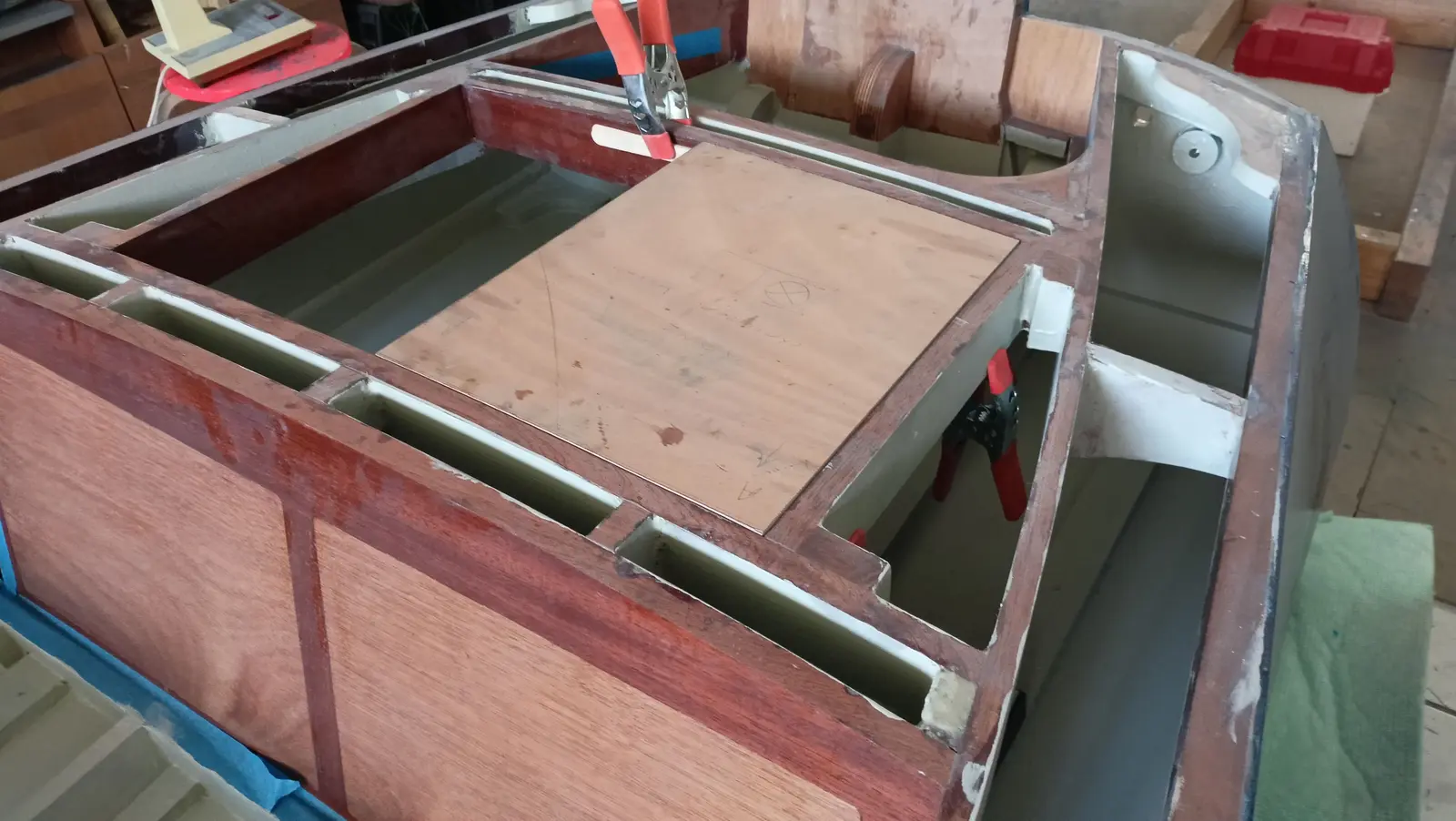
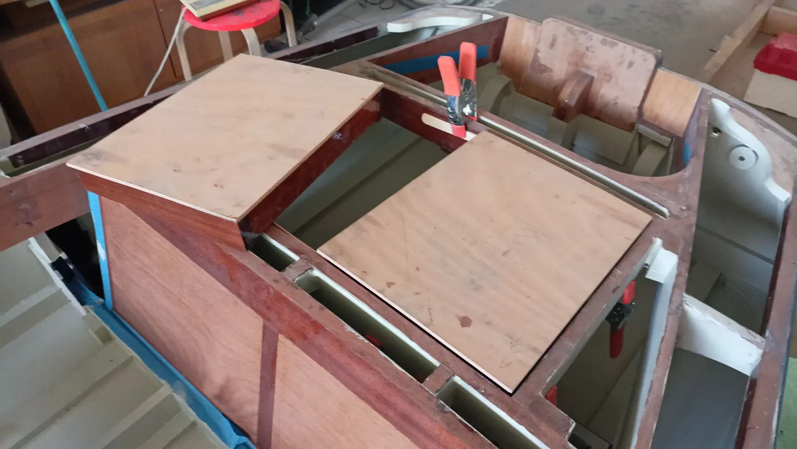
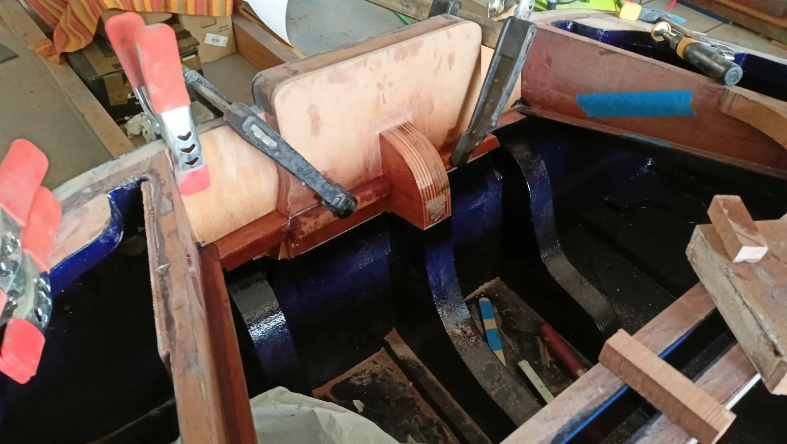
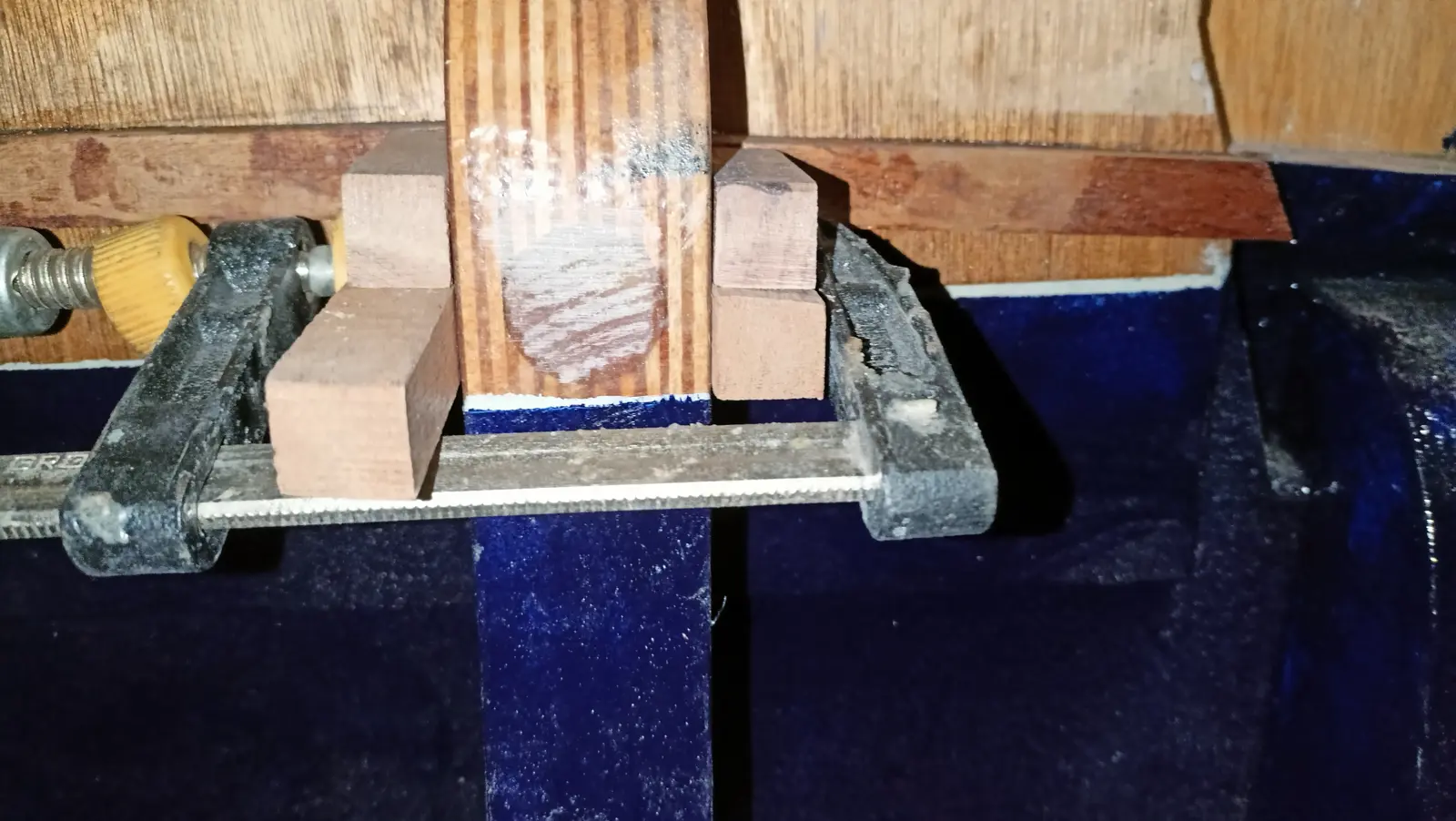
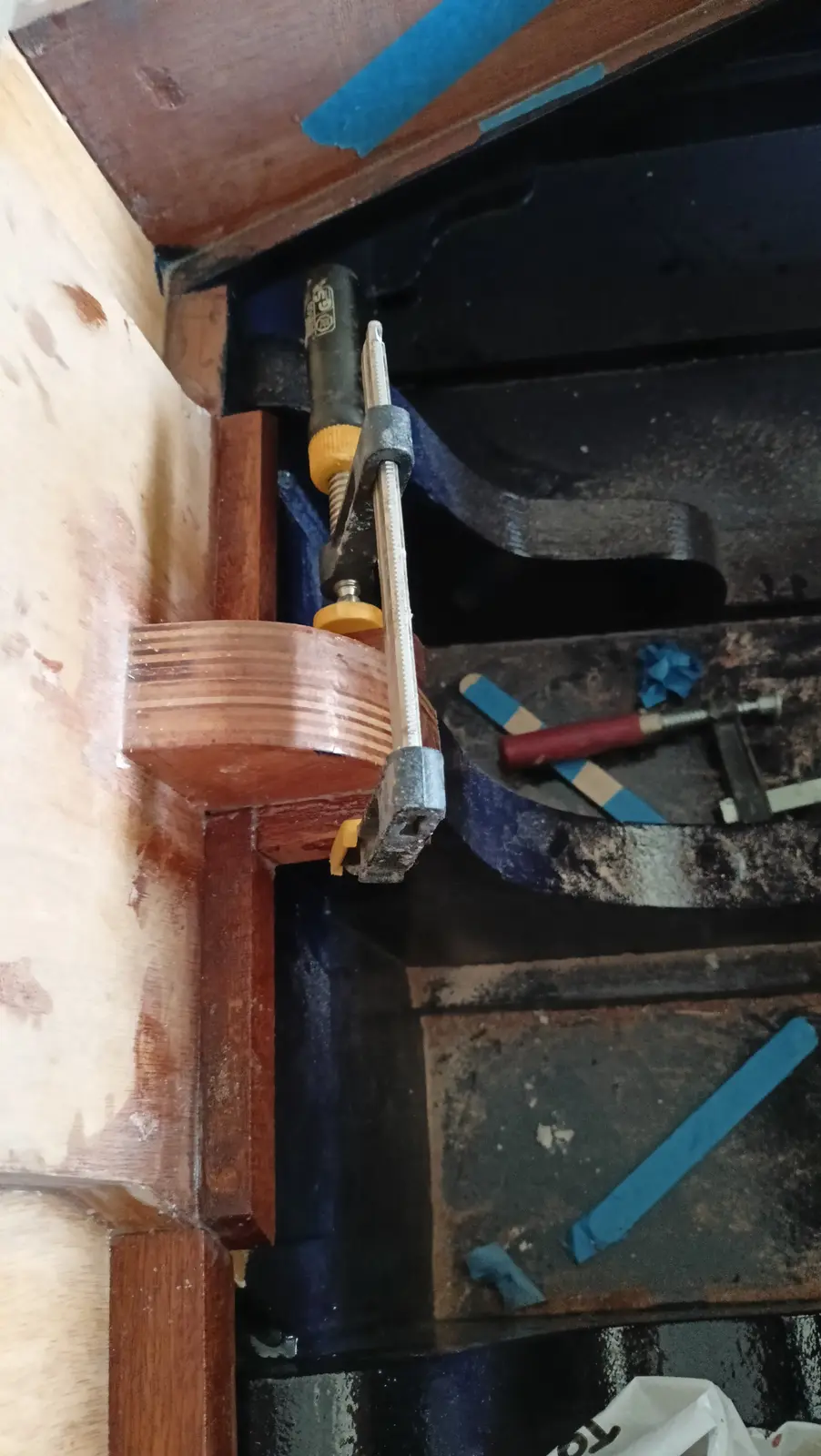
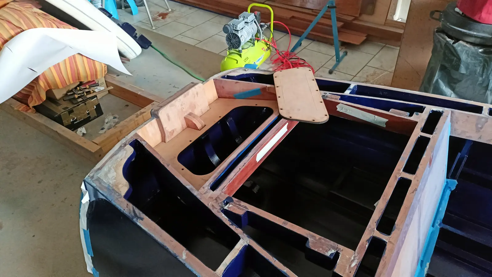
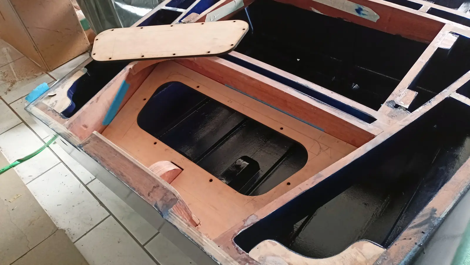
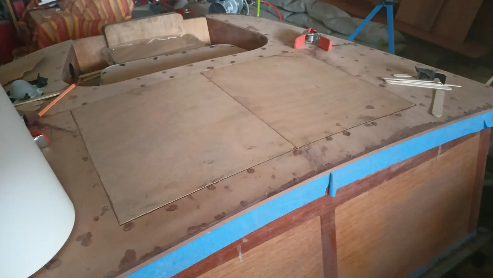
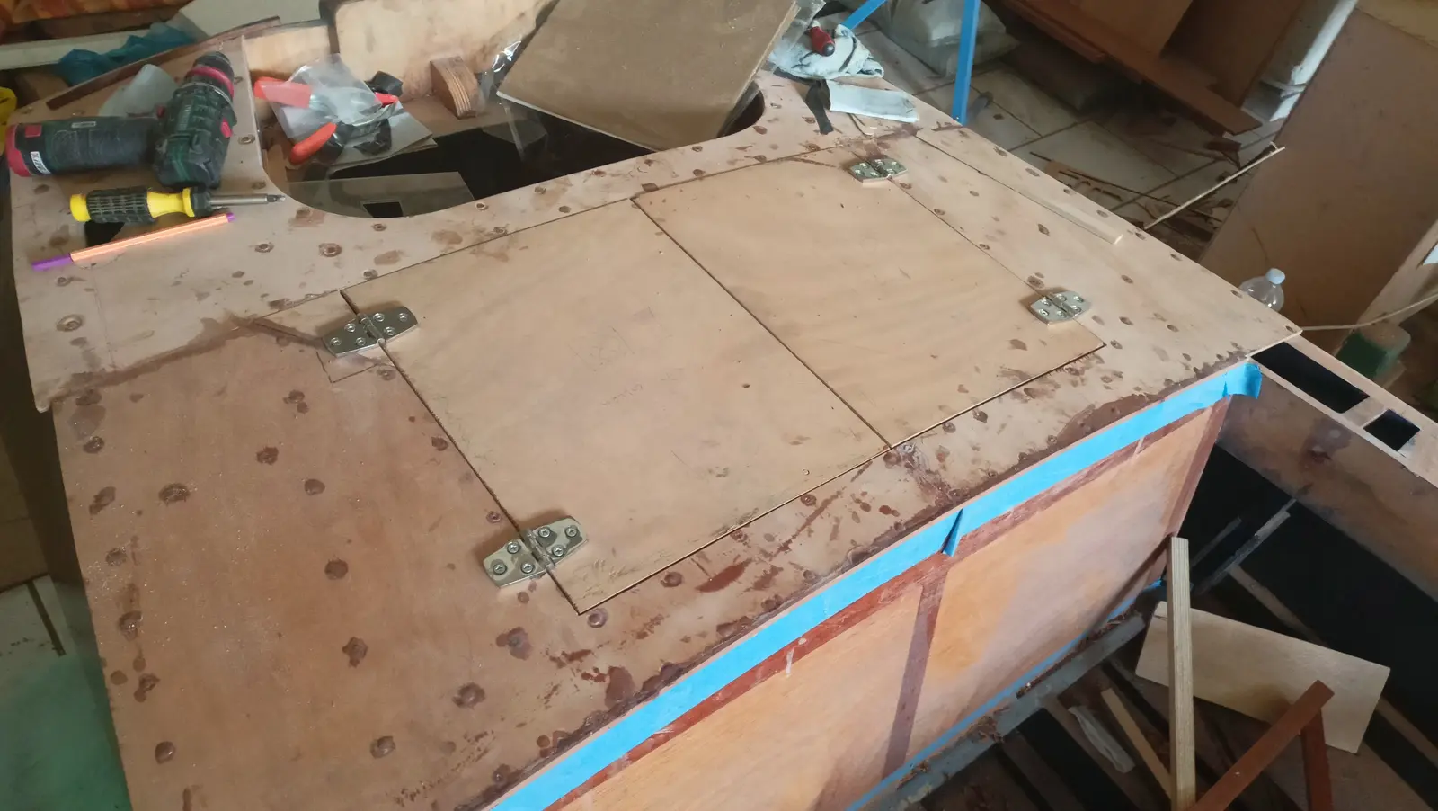
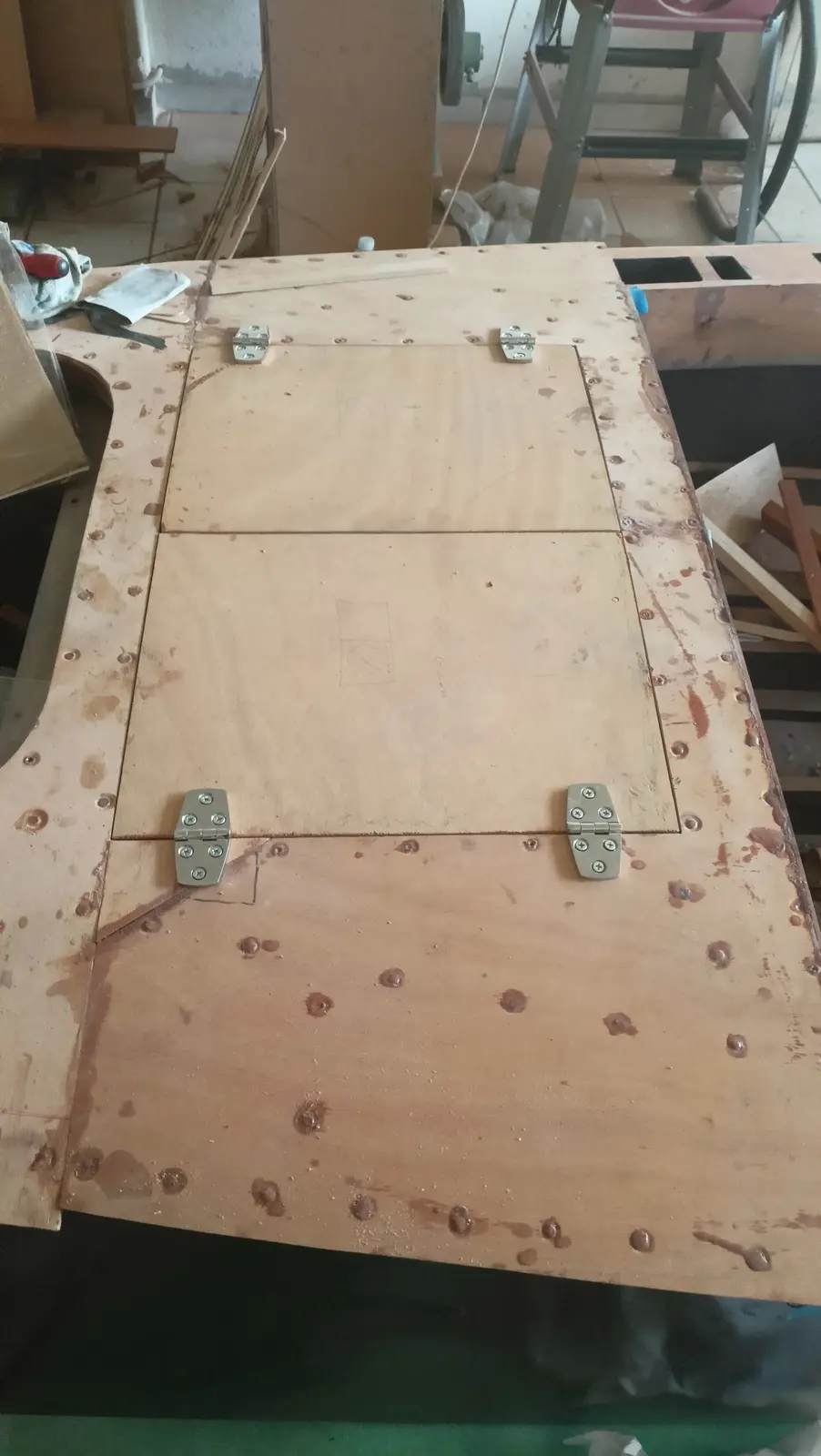
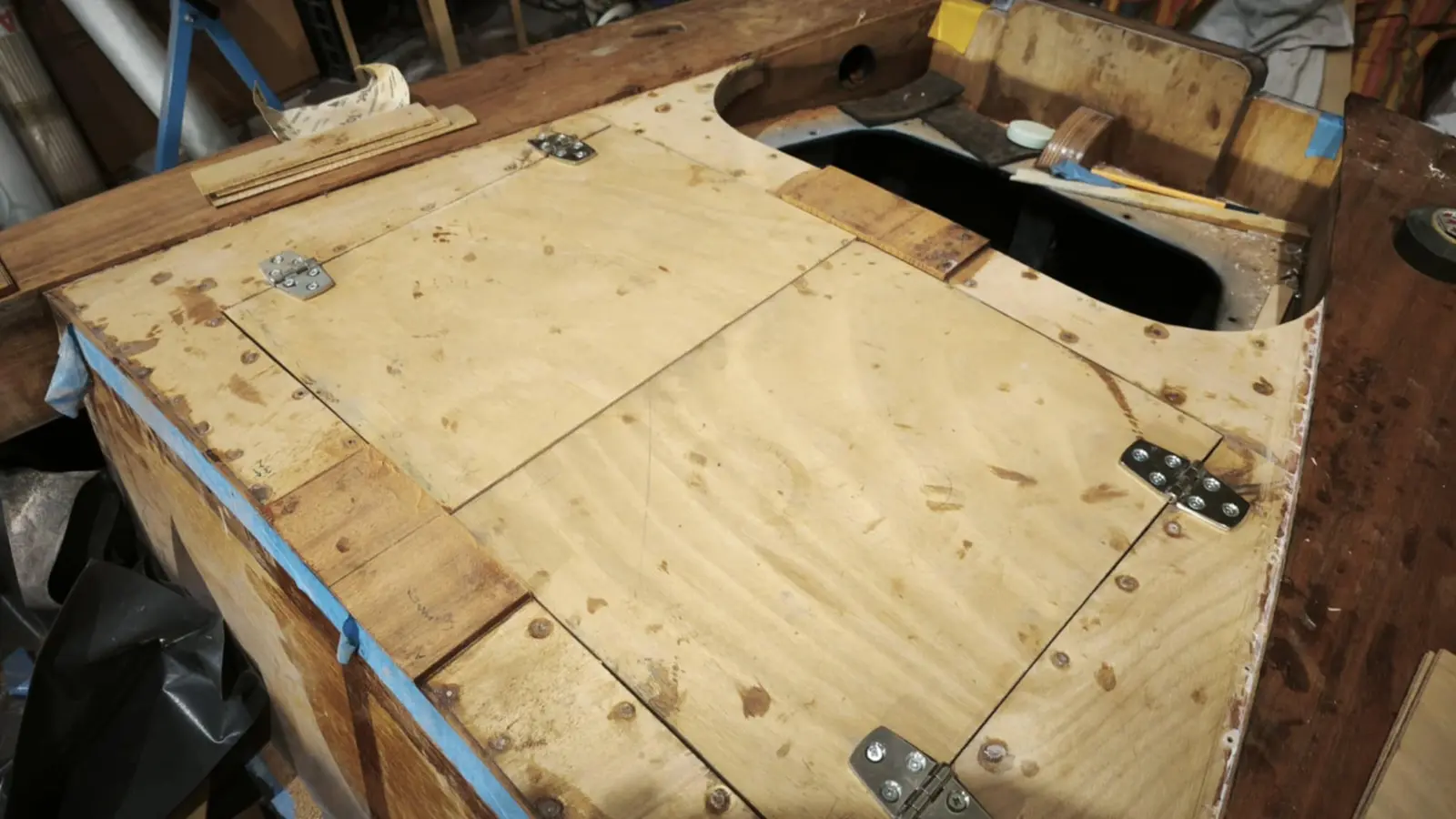
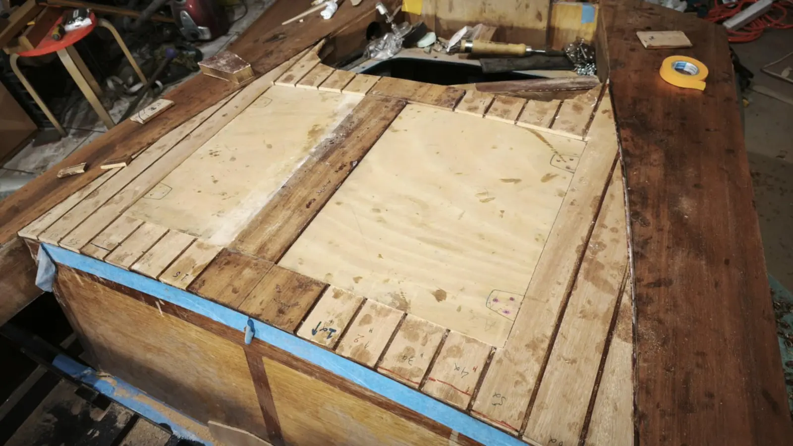
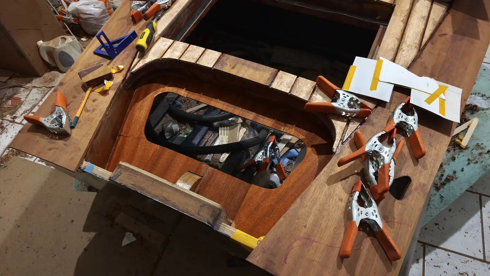
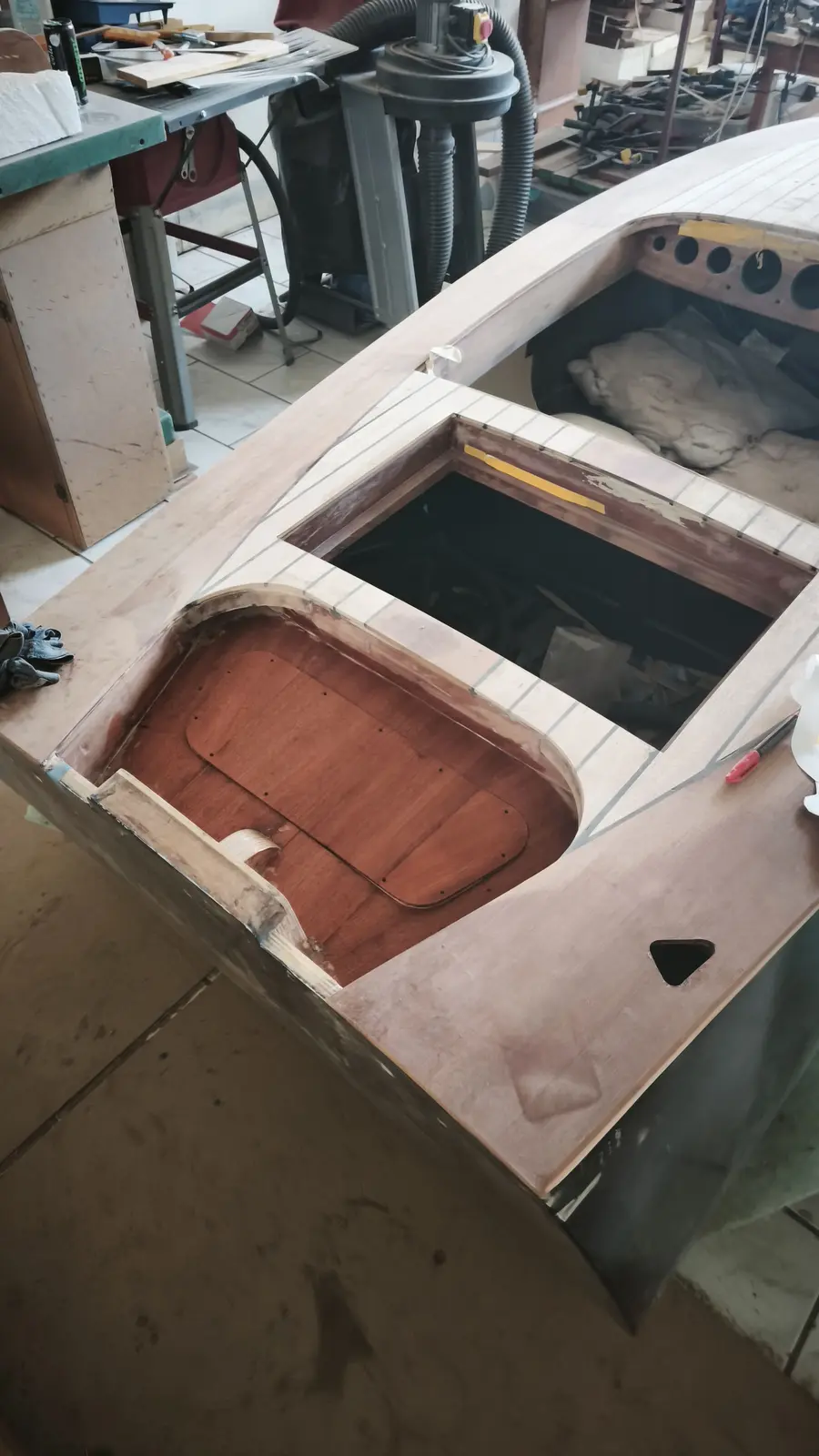
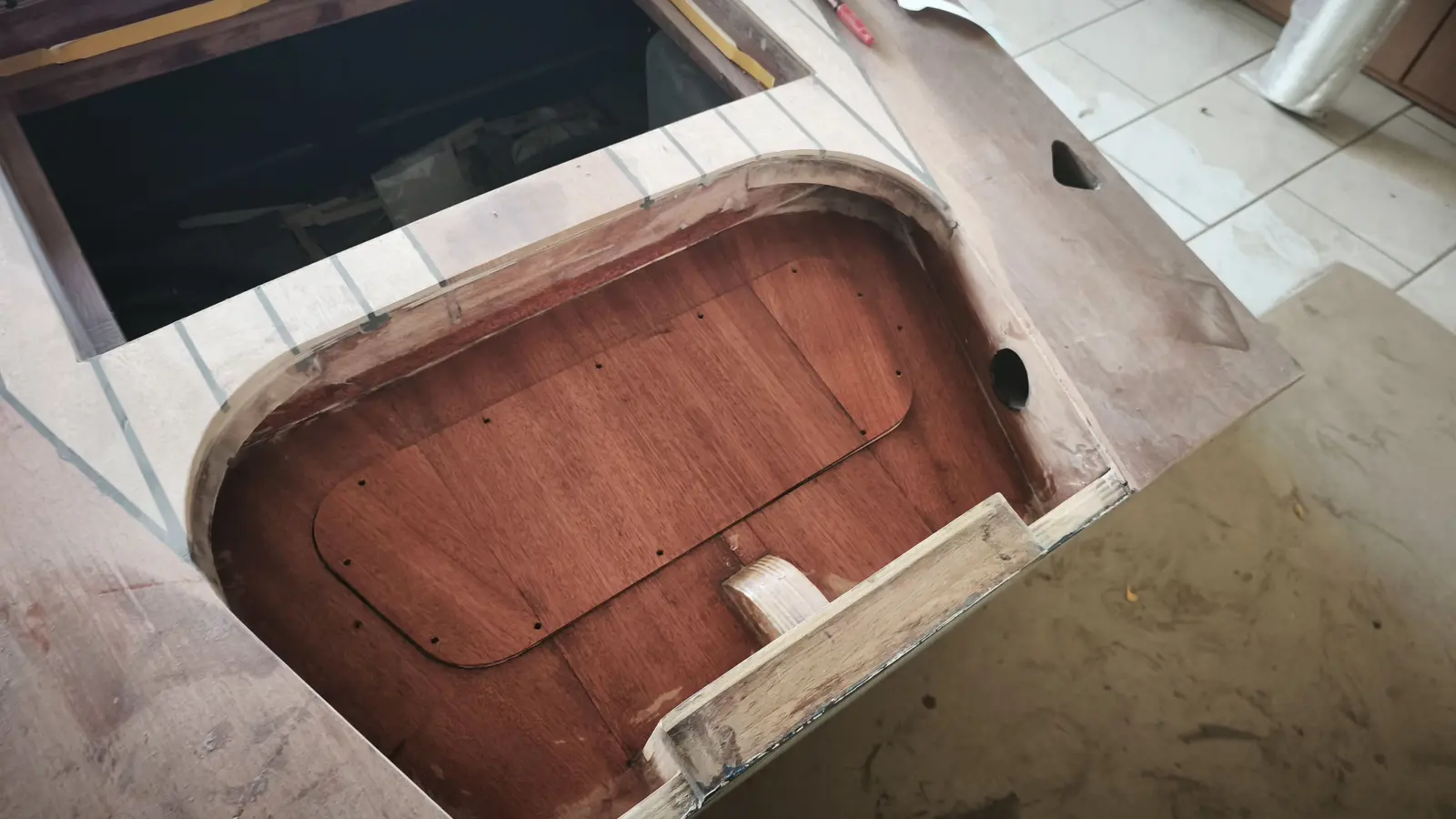
The next job was fitting the locker behind the seat. The locker frame stands about 3 mm off the sides of the boat (two thin sticks, tongue depressors) and about 5 mm between the left and right halves. I decided to leave about half that margin as overhang on the lid. Some photographs of the process.

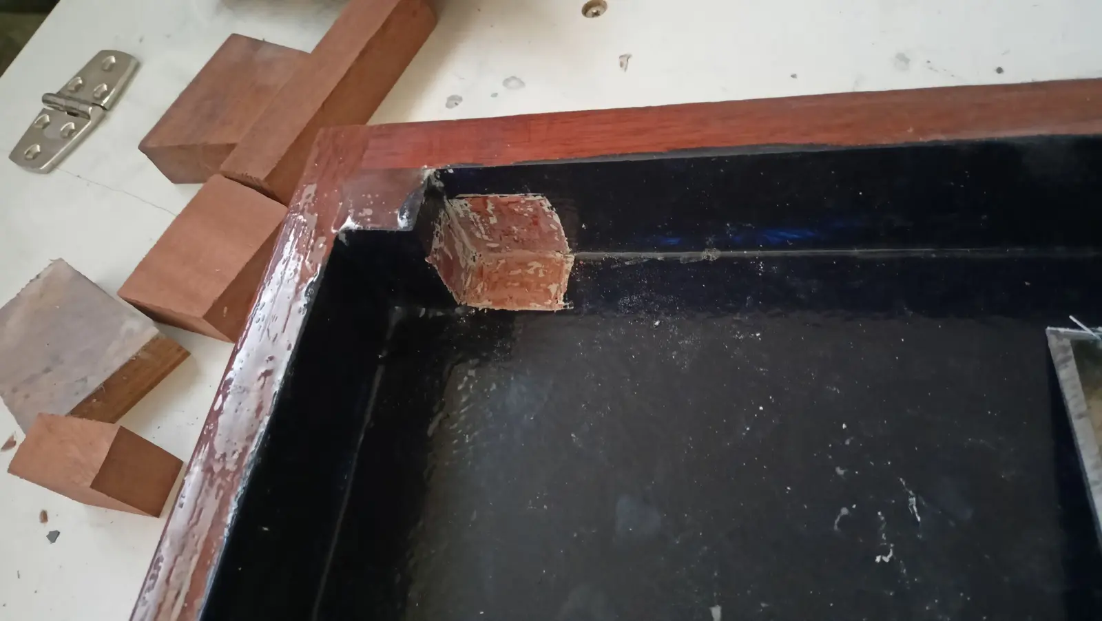
So the locker doors could be screwed on, reinforcements had to be glued both to them and to the boat's framework. The process is below.

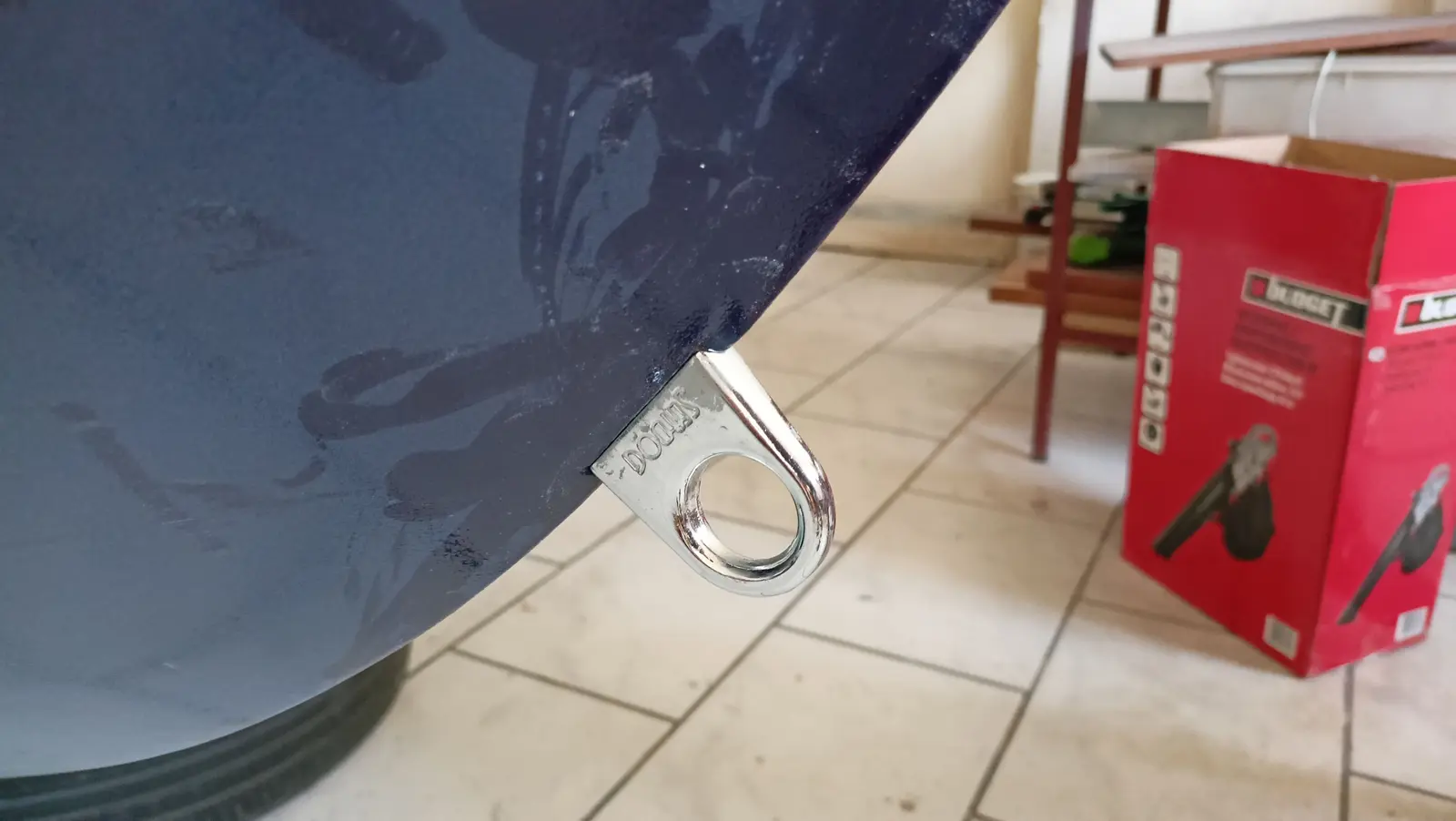
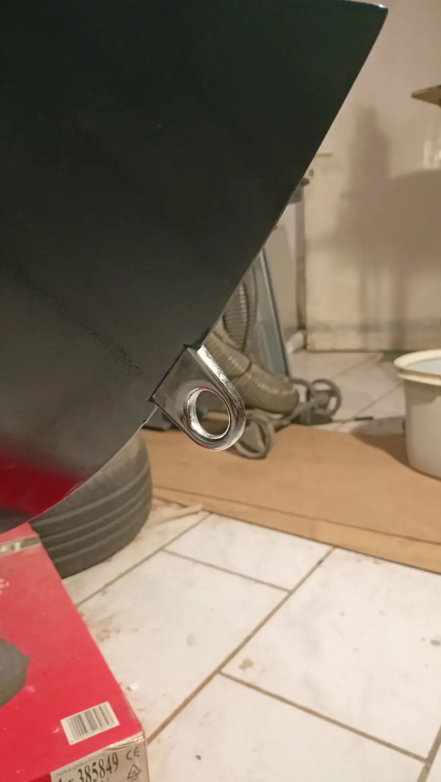
The holes for the forward and aft mooring cleats were drilled properly.

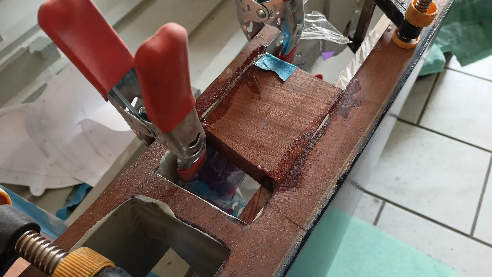
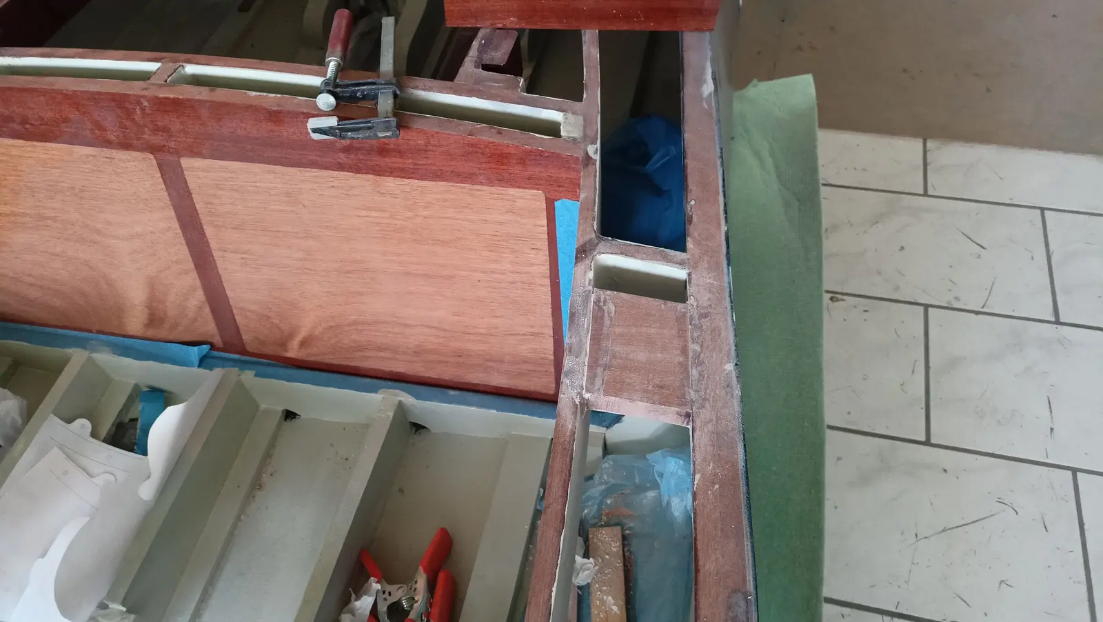
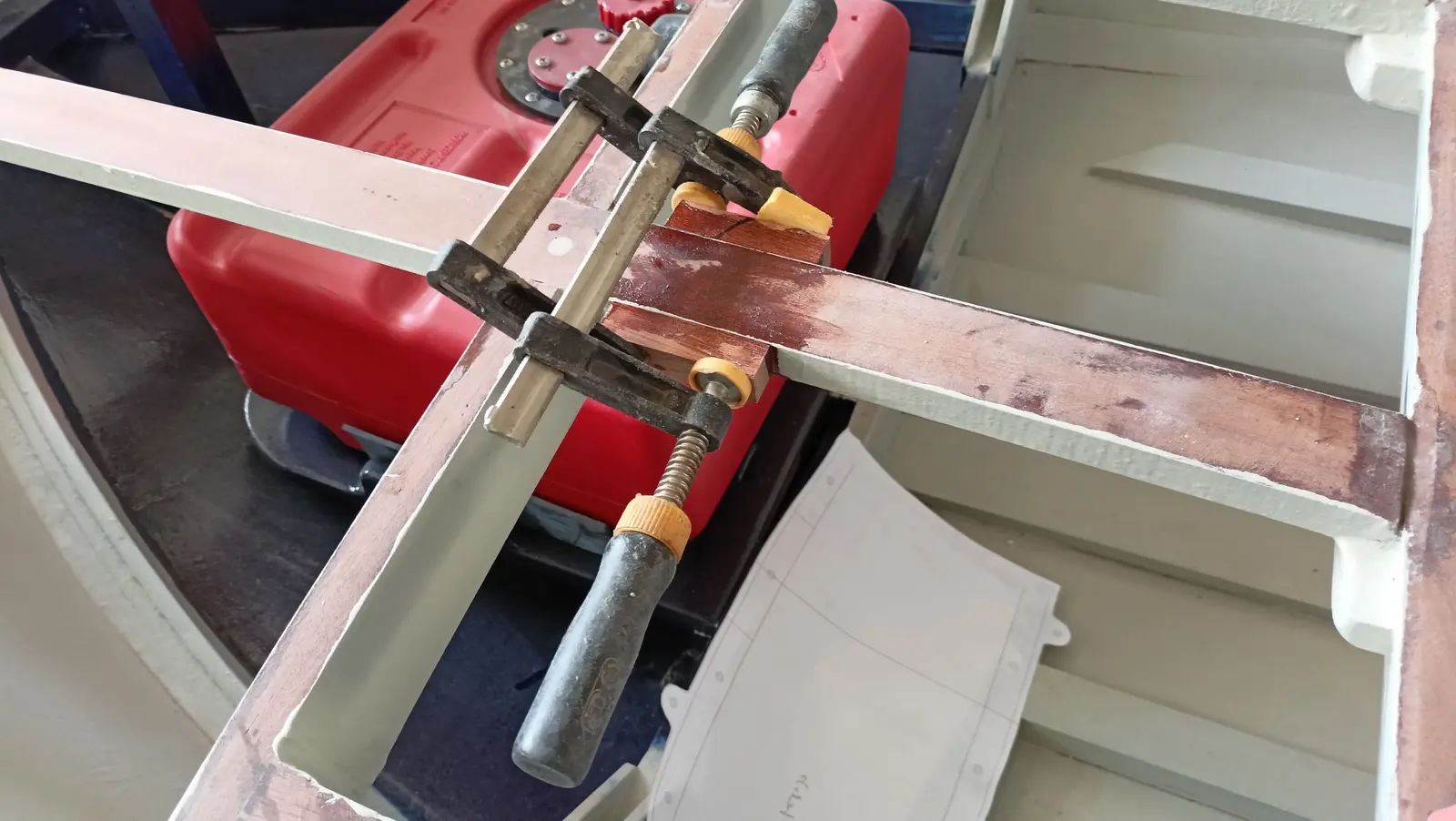
The next job, which needed a good deal of thought and study, was the correct position for the stainless fittings (cleats, rowlocks and so on) on the top of the boat. The problem I ran into was that because of the control box I could not put the rowlock very far forward, so that it would be in the right place for comfortable rowing when I am sitting on the seat back. The right position would be about 40 to 50 cm forward of where I sit. That was not possible and it will go a bit further aft, about 30 cm. So a reinforcing block was glued in so the structure will take the load from the oars.

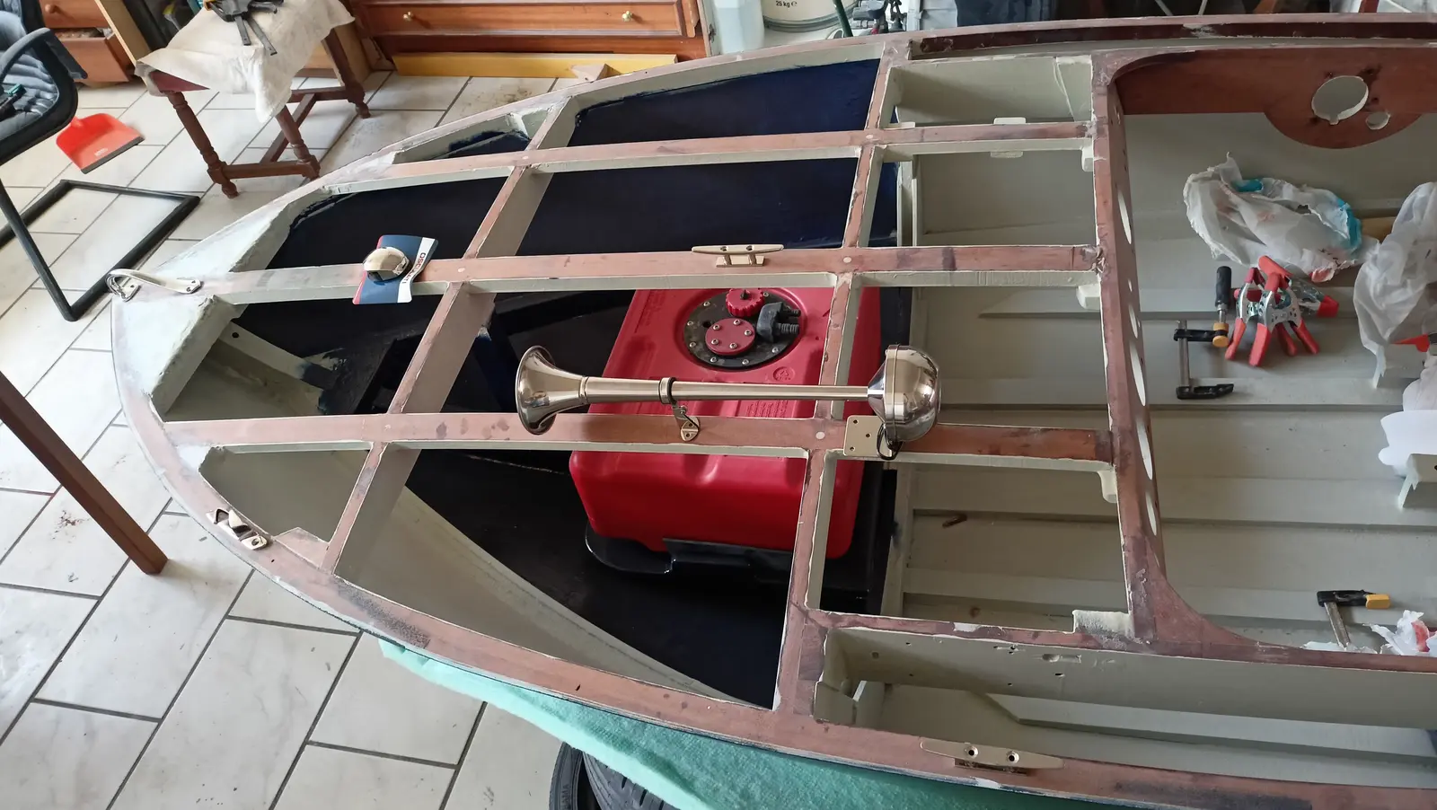
At the forward end, the stainless fittings and the red and green light will be installed as in the photograph below. Only the fuel filler cap is missing, which will go directly above the tank.

For the horn, as can be seen in the photograph, two small blocks had to be glued in for the screws to go into. I decided the horn should go at that point and well forward of the dashboard, so that a spray guard can be fitted if I decide on one.

Finally (much later, but I am showing it here) two thin pieces were glued on to increase the width, in case I wanted the stainless fittings I am going to use to be flush mounted.

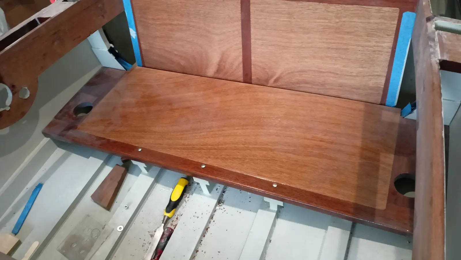
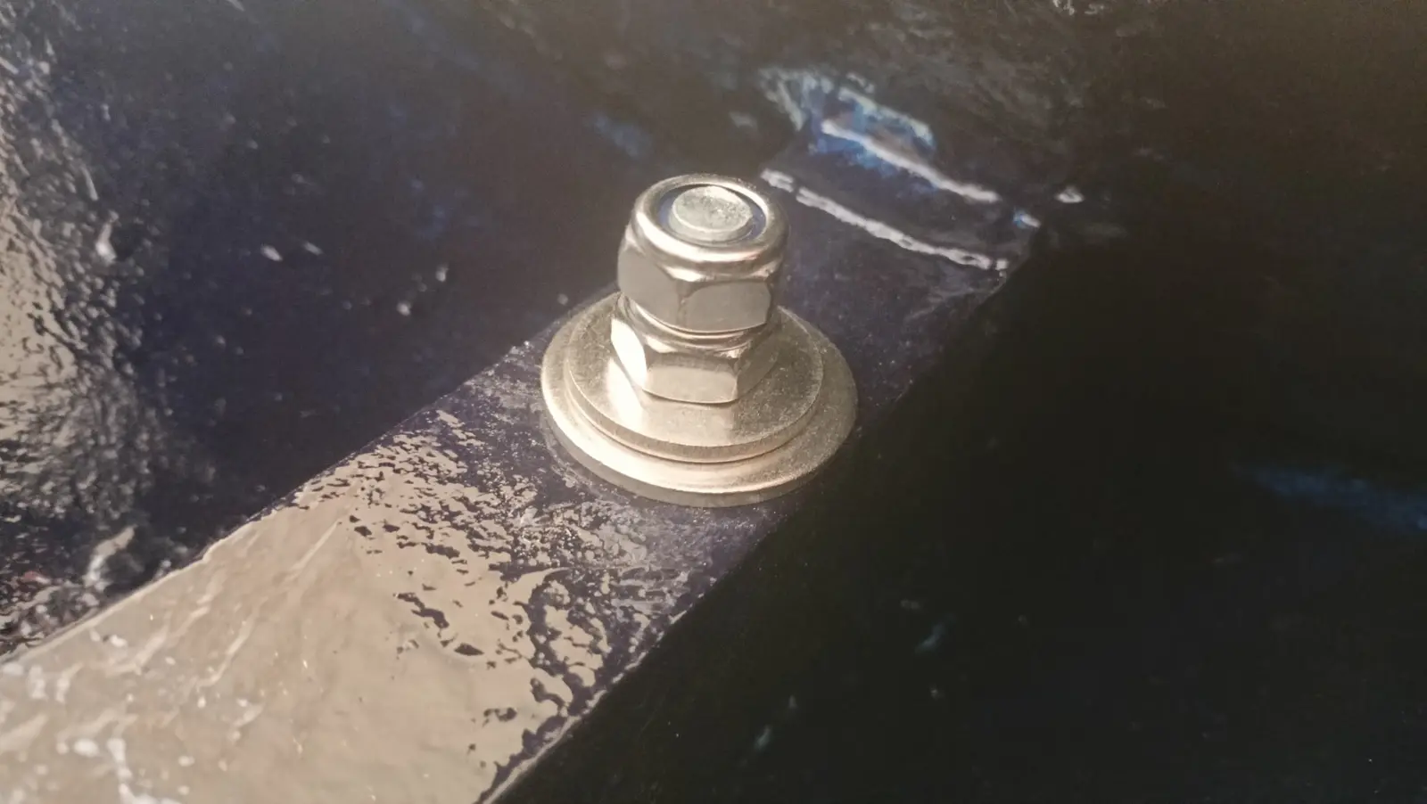
The seat installation was finished. All that is left is to tidy the bolt holes up a little with the router. To get the insert to sit at exactly the right height I made the arrangement below. I filled the hole with epoxy and pushed the insert in, having first sprayed the insert, bolt, washer and nuts with silicone spray so they would not stick. That way a thread was formed in the epoxy and I can take the insert out at some point if I want to. I do not think it will ever be needed as it is stainless, but the option is there...

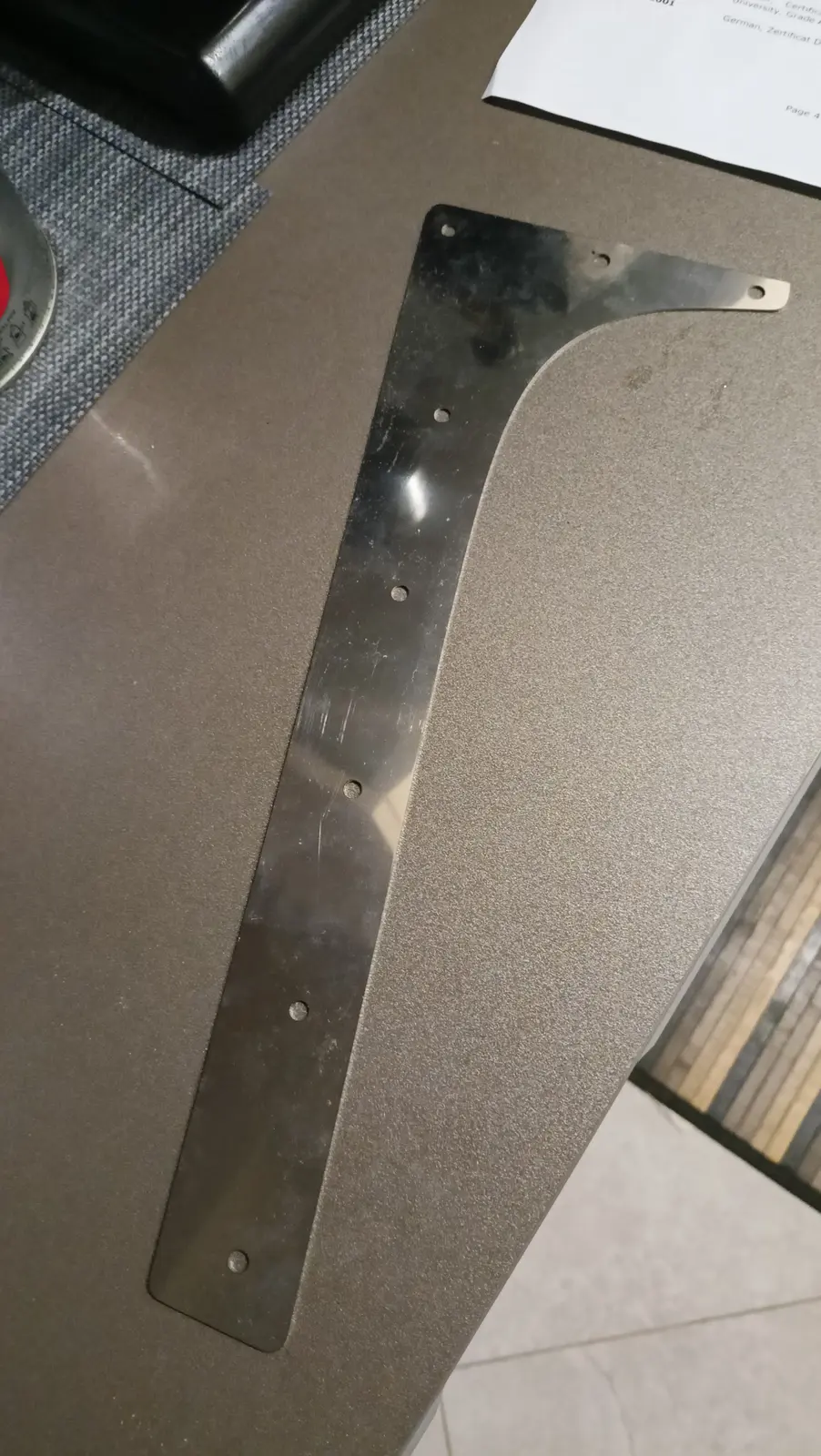
Finally I laser cut the stainless fittings for the aft end (left and right).

With all the interior work finished, the whole hull was painted.

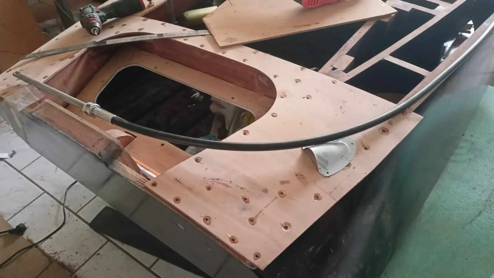
Then a hole was cut aft where all the outboard cables will run forward (control box, battery, steering cable and so on).

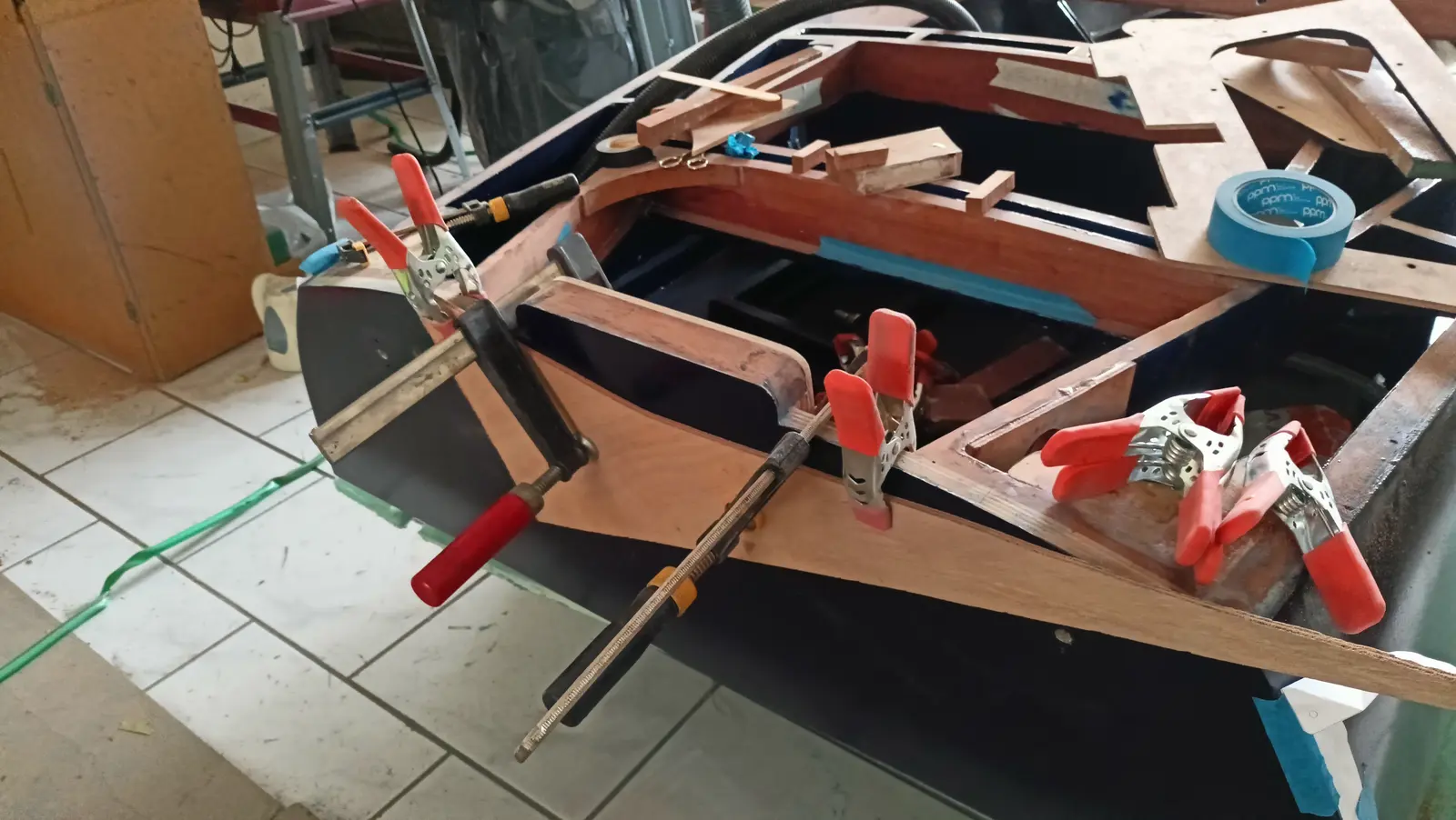
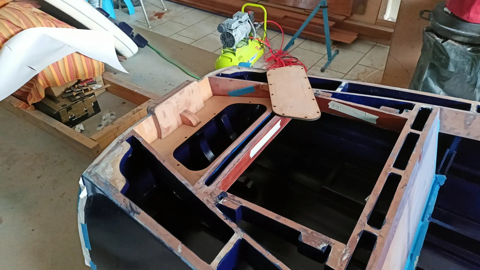
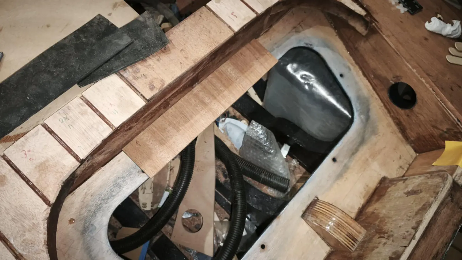
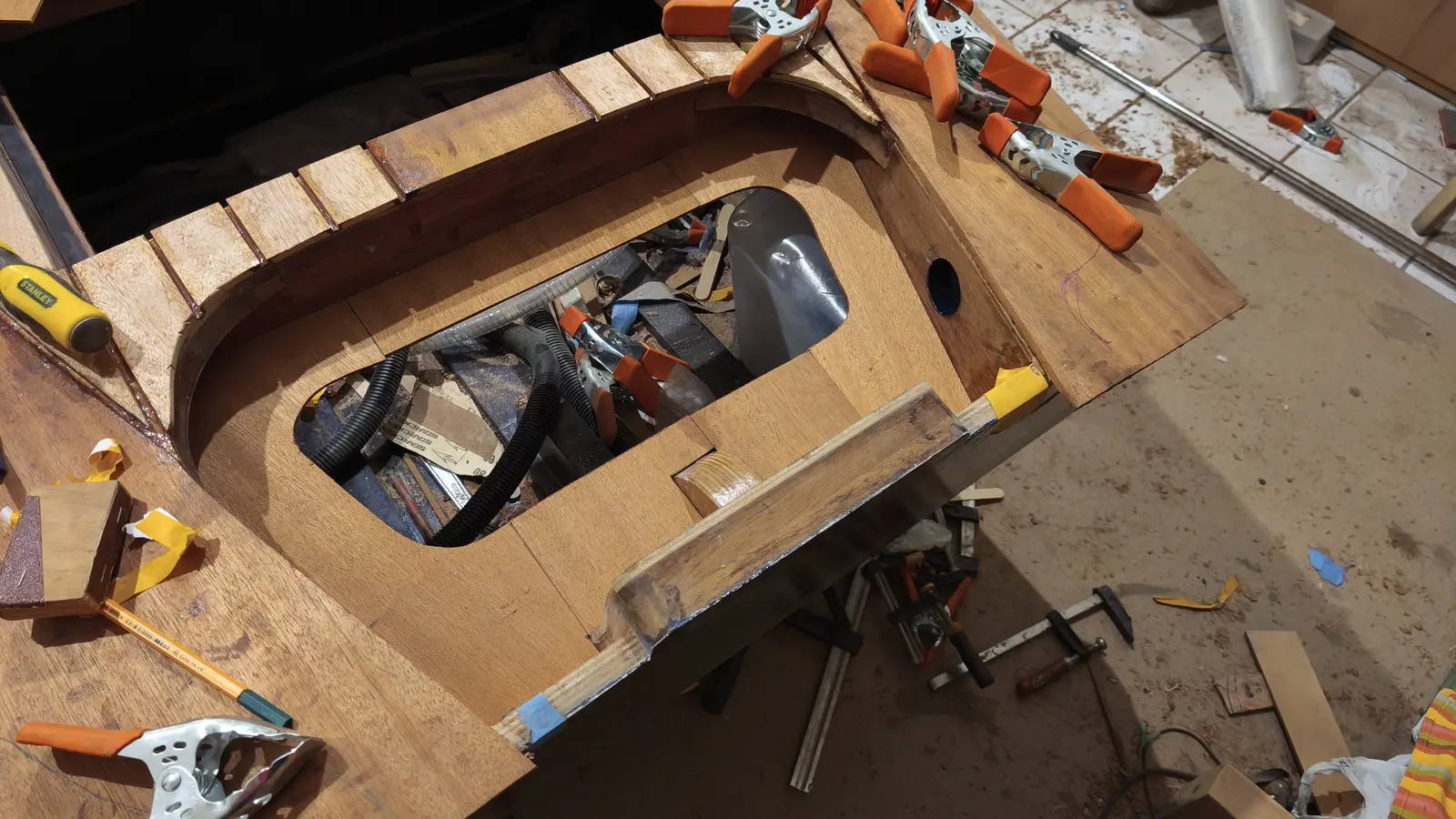
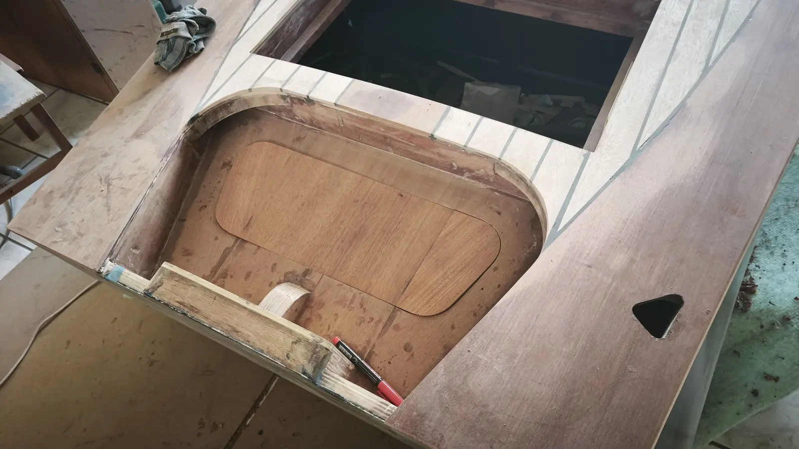
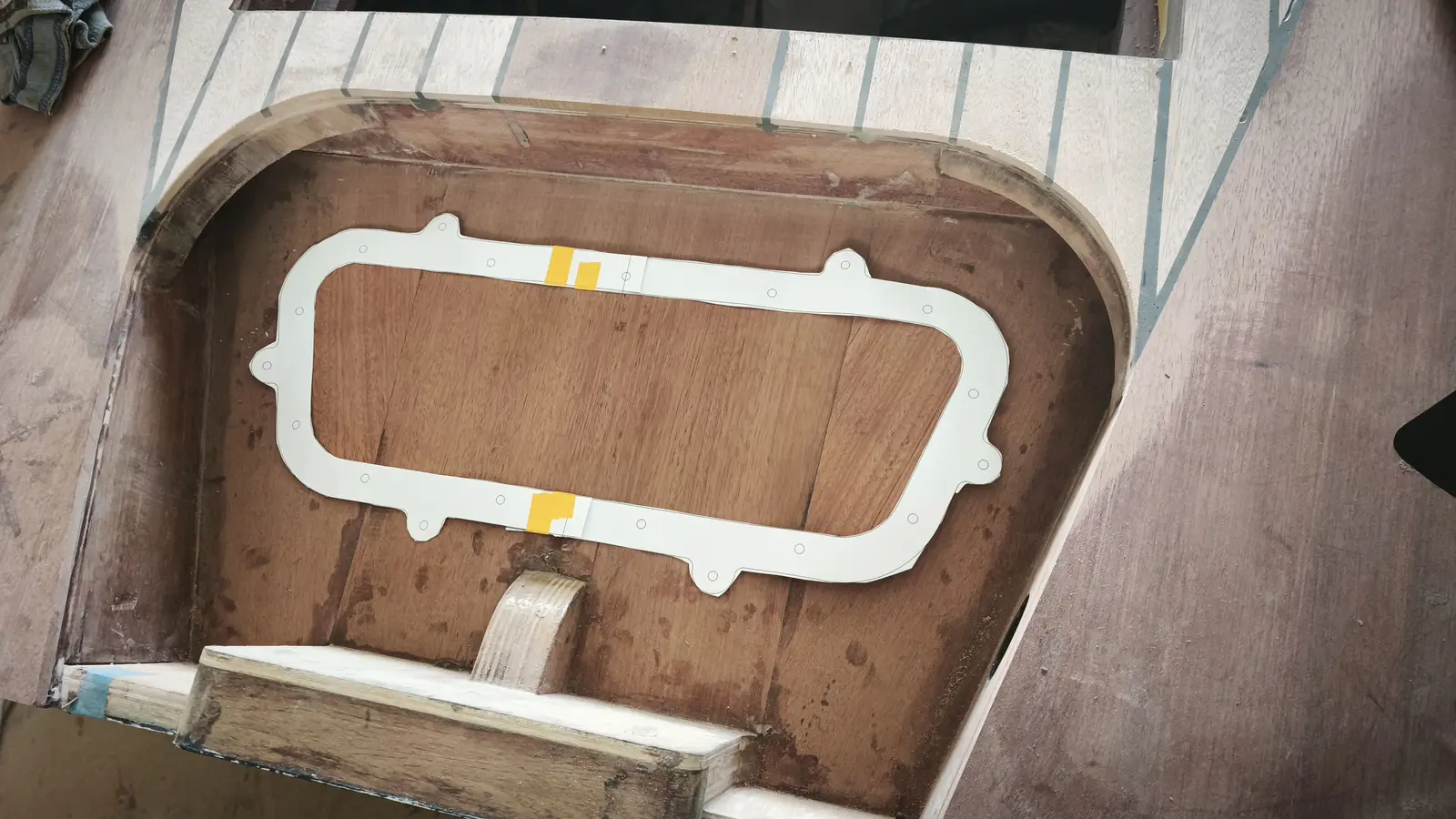
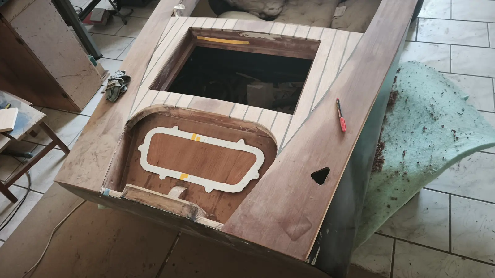
The next job was gluing in the aft locker. First, thin pieces had to be glued round the edge for the plywood to sit on.

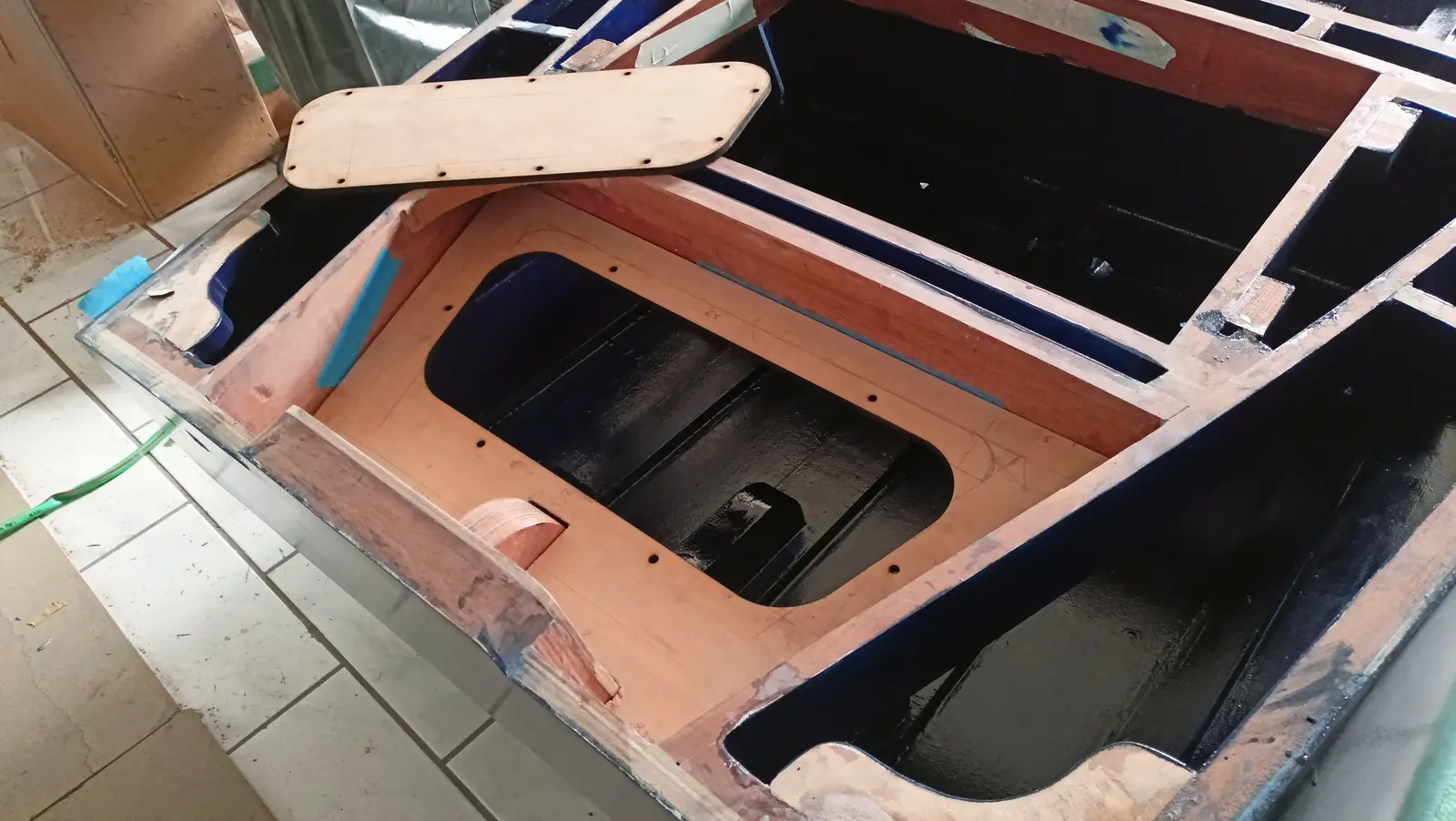
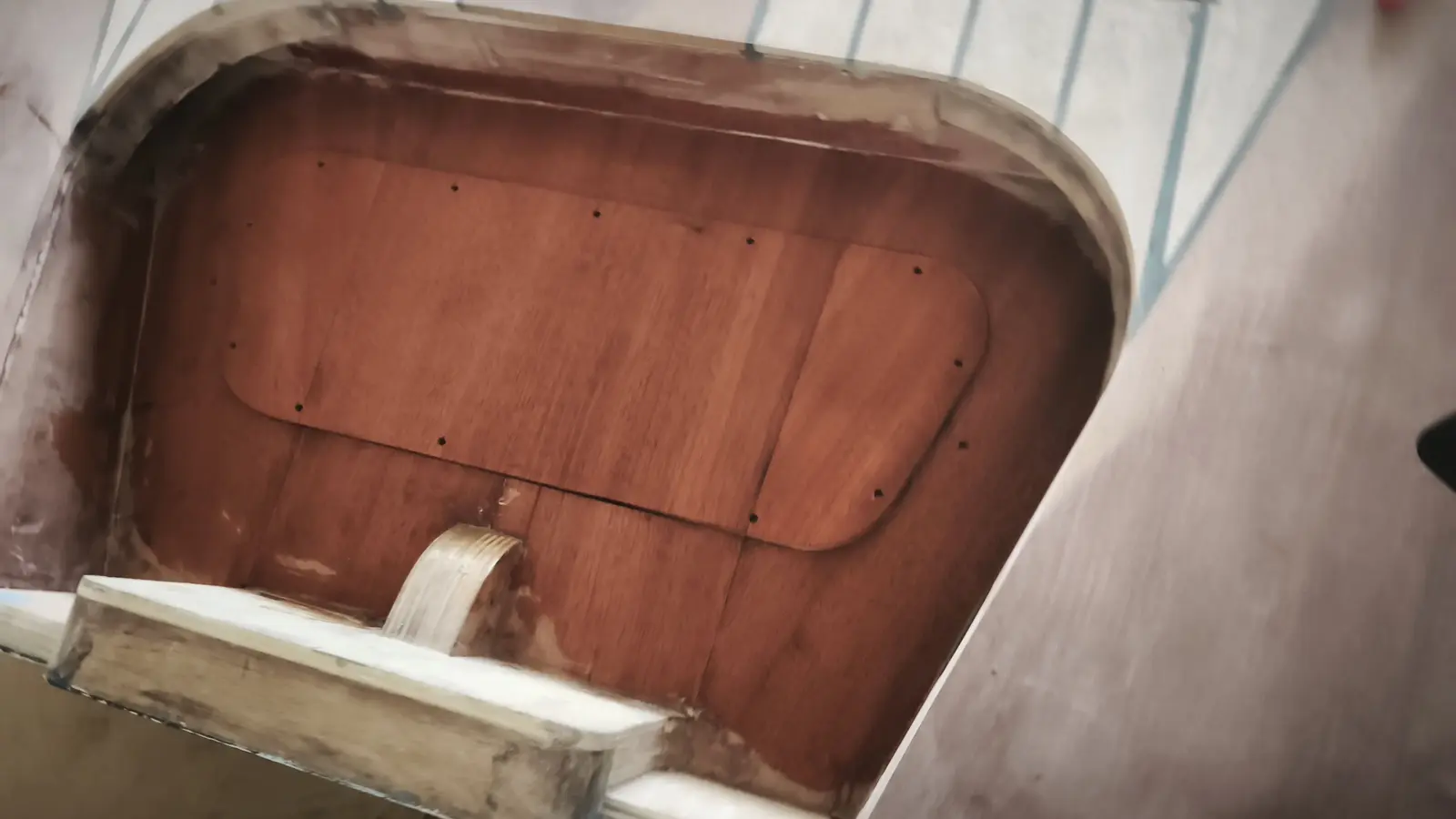
The plywood was laser cut to the shape below.

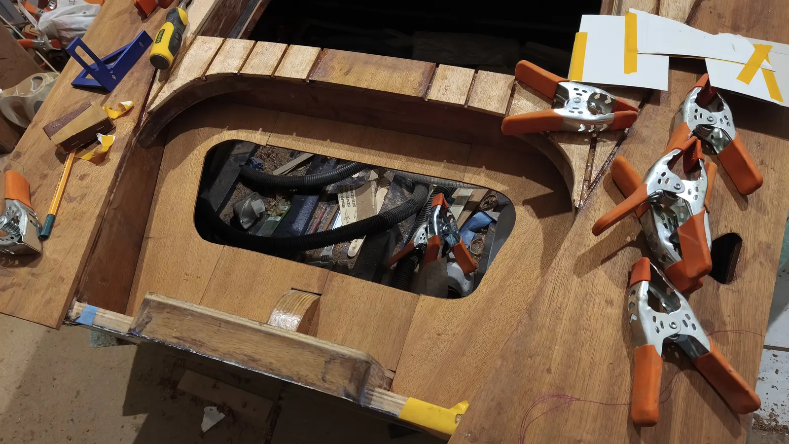
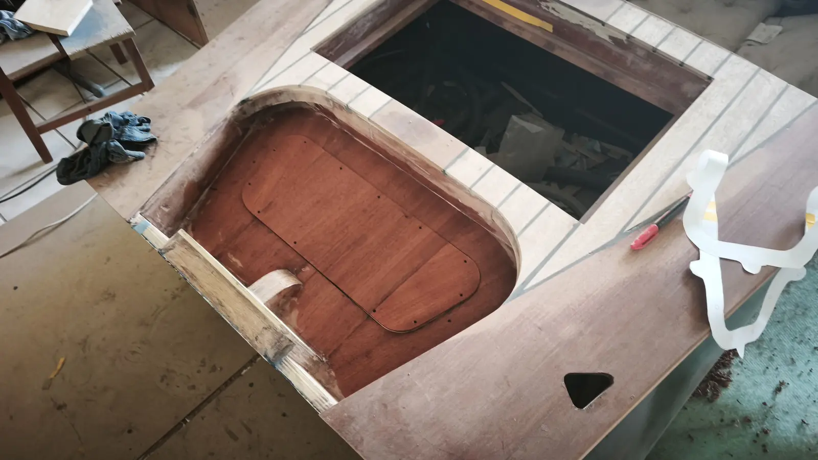
The next job was gluing it in.

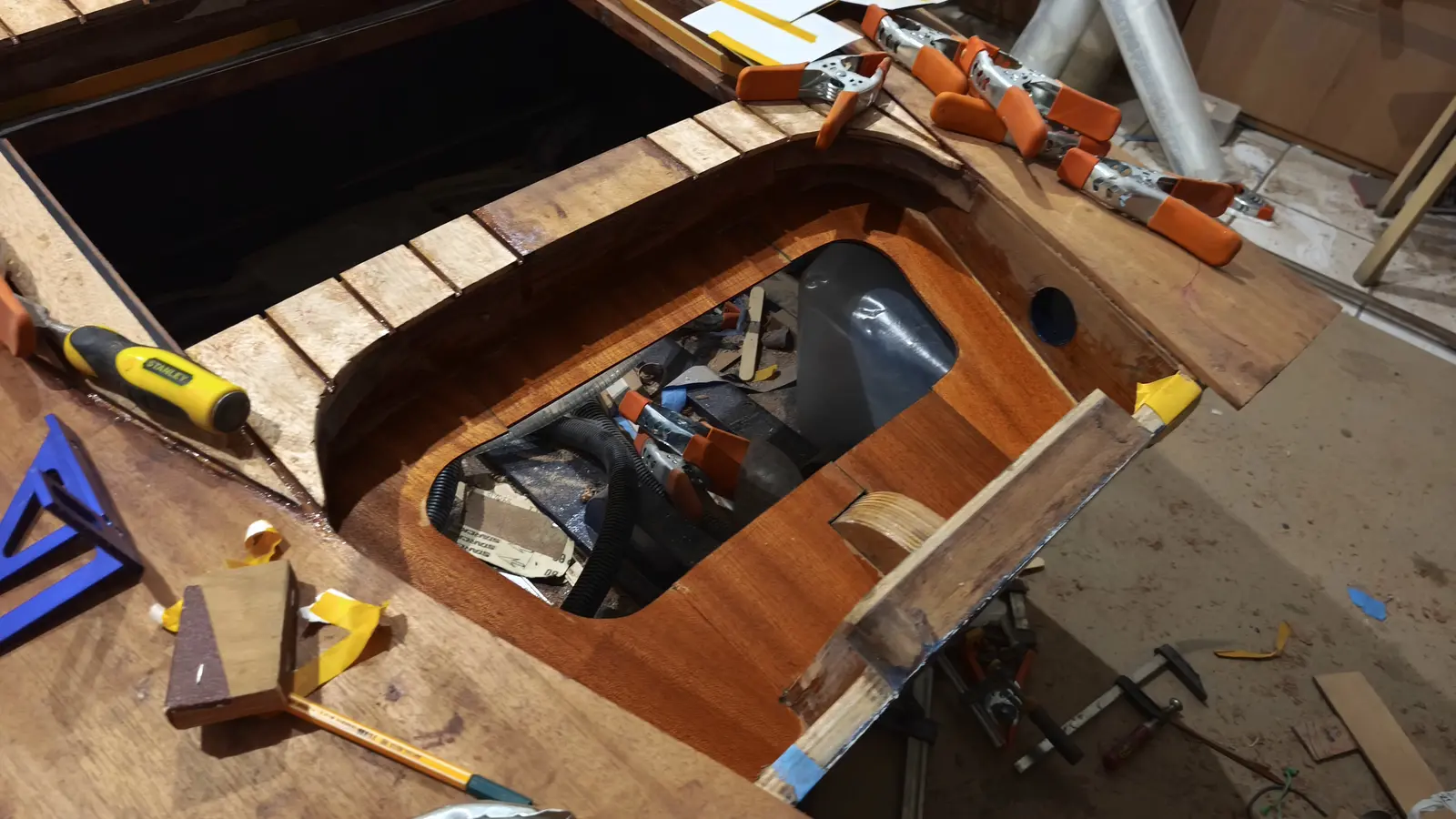
Once it was glued I also glued on the second curved piece above the plywood, which the "deck" will sit on.

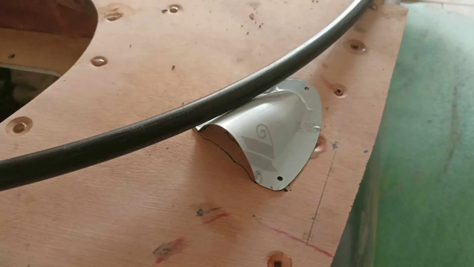
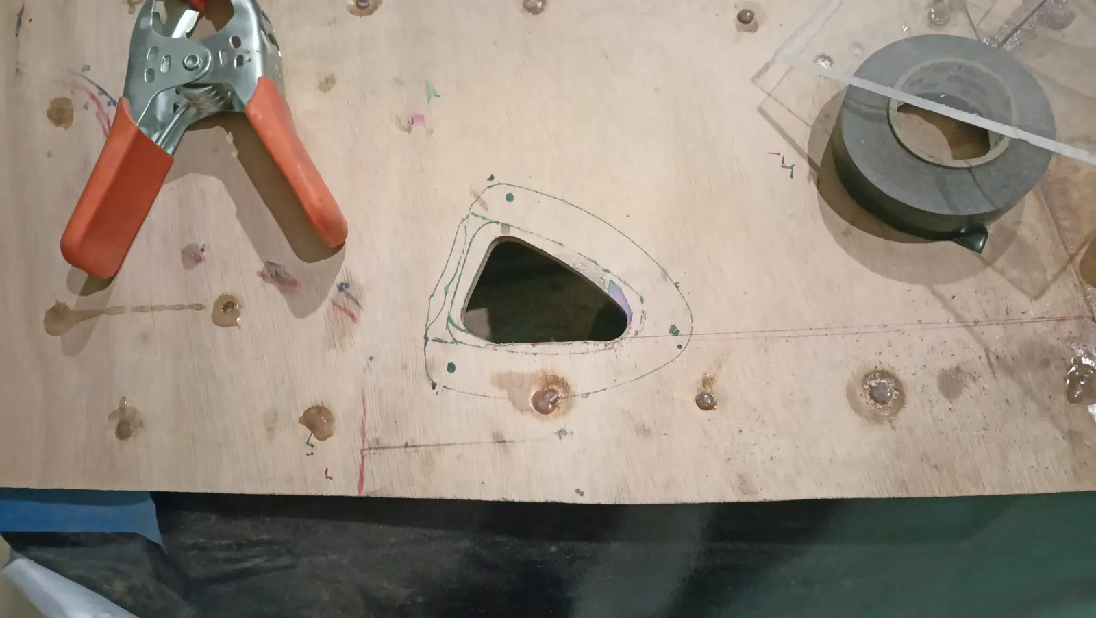
The last job before gluing on the plywood for the top of the boat was drilling two holes for the steering cable to pass through. I have not kept a photograph of the finished result. The diameter is about 20 mm.
Link

Fitting the flotation material

  1. Introduction

Ensuring the boat is unsinkable is one of the most important safety considerations in building a small craft. The term "unsinkable" does not mean the boat cannot take water inside it, but that even in the event of complete flooding it has enough positive buoyancy to stay on the surface.

Achieving that depends on installing suitable flotation materials, which act as a permanent reserve of buoyancy. These materials must stay effective for the whole life of the boat, must not be affected by the marine environment, and must retain their properties even after long use.

Just as important as the quantity of material is its correct distribution within the hull. The point of the flotation is not only to avoid sinking, but to maintain the boat's stability after flooding. Correct geometric distribution between bow, stern and sides helps keep the boat as close to level as possible (level flotation) and reduces the risk of capsize.

A conservative design approach is used in this build. The natural buoyancy of the wooden structure is not taken into account in the calculations, so that the flotation system has an adequate safety margin regardless of what the boat itself contributes.

  1. Analysis and choice of flotation material

The purpose of installing flotation material is to ensure the boat has positive buoyancy in the event of complete flooding. The choice of material is based on its resistance to the marine environment, its chemical stability, zero water absorption, its mechanical properties, and how easily it can be worked and fitted.

The following categories of material were considered:

Extruded polystyrene (XPS)

Extruded polystyrene was rejected, as it has no resistance whatsoever to hydrocarbons. Even a small quantity of petrol or other fuel causes rapid chemical breakdown of the material, so that it dissolves and loses its mechanical and buoyancy properties.

Polyurethane foam (PU)

Two-part polyurethane foam (pour foam) was rejected, because over time it can absorb moisture, increasing its weight and reducing its effectiveness.

Closed-cell polyurethane foam sheet was also considered. Although it behaves better with regard to water absorption, it is very brittle and stiff, so it does not conform well to the curves of the frames and it crumbles when worked.

Polyethylene foam sheet (PE)

Closed-cell polyethylene foam sheet was chosen as the most suitable solution.

The main advantages of polyethylene (PE) foam are:

Practically zero water absorption.

Excellent resistance to fuels, oils and chemicals.

High resistance to ageing.

Great flexibility, allowing it to conform easily to the curves of the boat.

Low weight in itself, as its low density allows a lot of net buoyancy per unit volume.

Easily worked.

Although it costs around ten times as much as the other materials, its reliability, durability and long life fully justify the choice.

  1. Theoretical background and calculation of the flotation required

According to Archimedes' principle, any body immersed in a fluid experiences an upthrust equal to the weight of fluid it displaces. In fresh water, each litre of displaced volume provides about 1 kg of buoyancy, while in sea water the equivalent is about 1.025 kg.

The calculations in this study are carried out on the basis of fresh water, which is the worst-case scenario.

The total mass of the metal fittings and permanent equipment is estimated not to exceed 100 kg, distributed roughly as follows:

Outboard engine: 56 kg

Lithium battery: about 4 kg

Steering, controls and other fittings: up to 40 kg

Before the flotation material is finally installed, all the components will be accurately weighed.

On the conservative assumption above (ignoring the buoyancy the wooden structure provides), a minimum of about 100 L of net flotation volume is required simply to offset the weight of the equipment.

For real safety, a safety factor of at least 1.5 is applied, setting the required volume at 150 to 180 L (or more, if the available space allows).

That choice ensures a significant reserve buoyancy, improves the boat's behaviour in the event of flooding, and ensures that, under the design conditions assumed, the boat will stay on the surface until a rescue is completed.

  1. Fitting process and geometric distribution

Correct distribution of the flotation material is as important as the total quantity. The aim is not only to stop the boat sinking, but to keep it as stable and as level as possible in the event of complete flooding.

Phase A, filling the bow

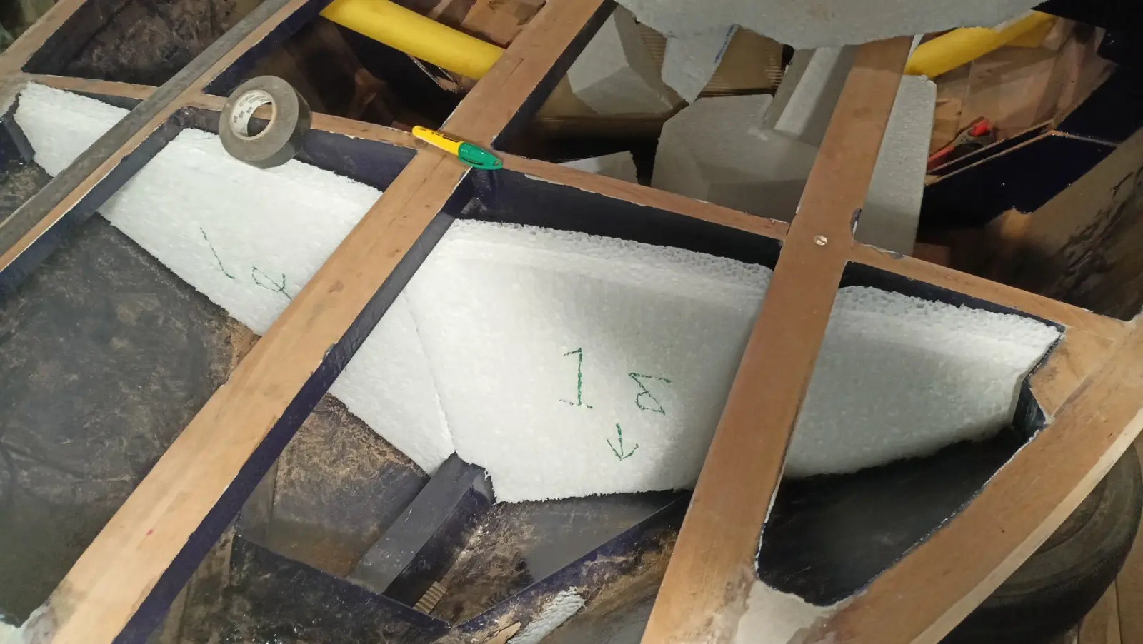
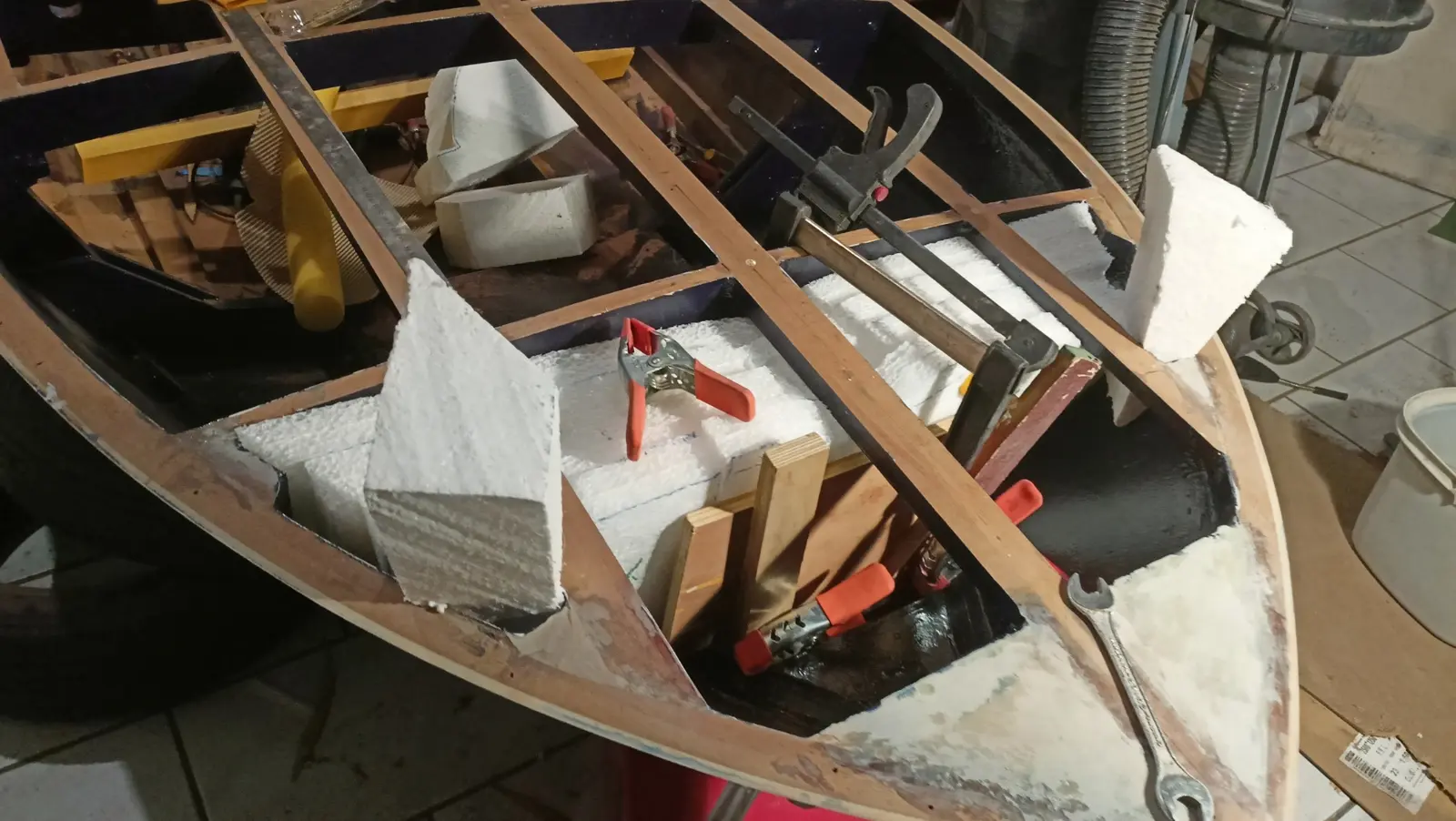
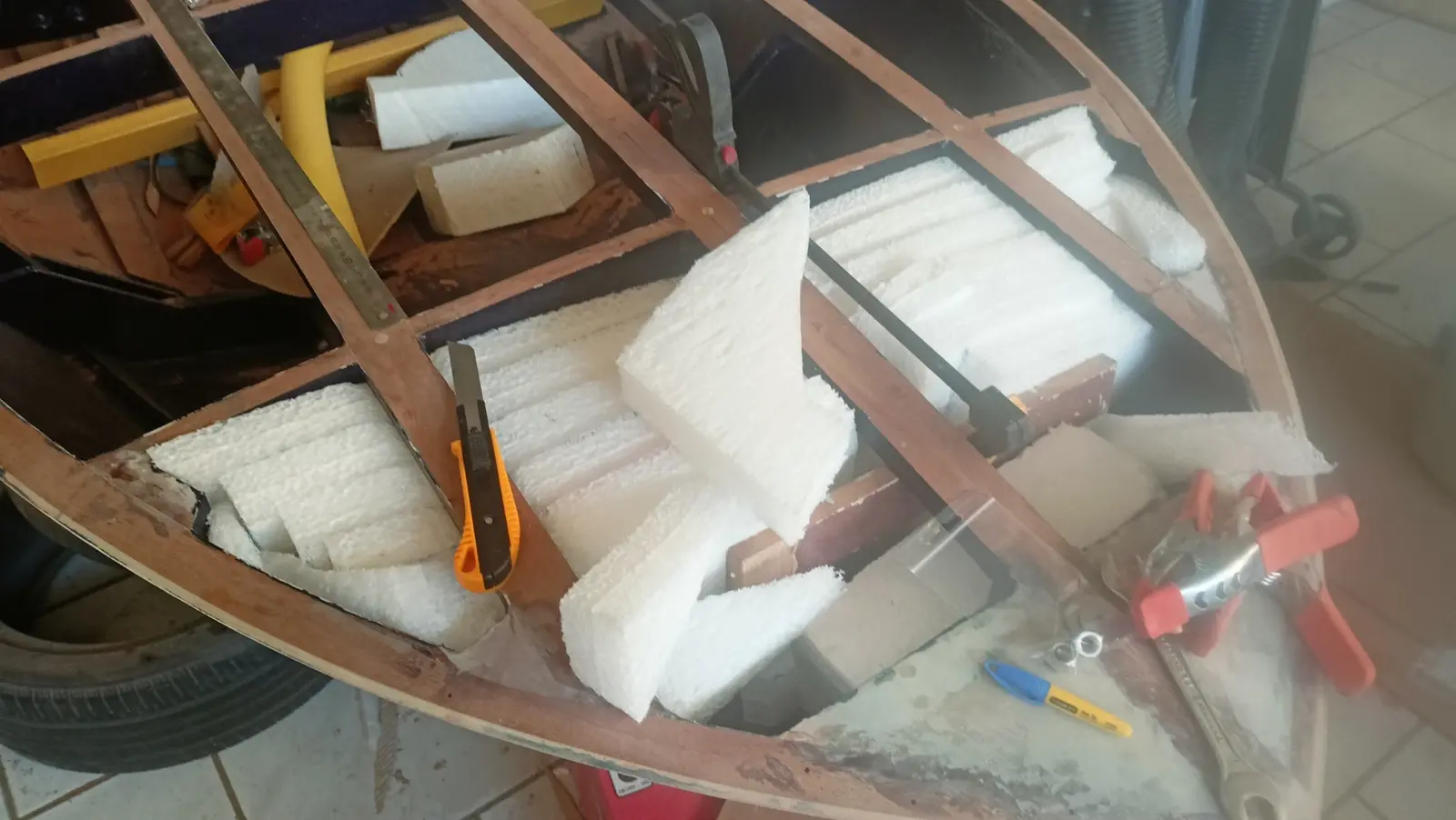
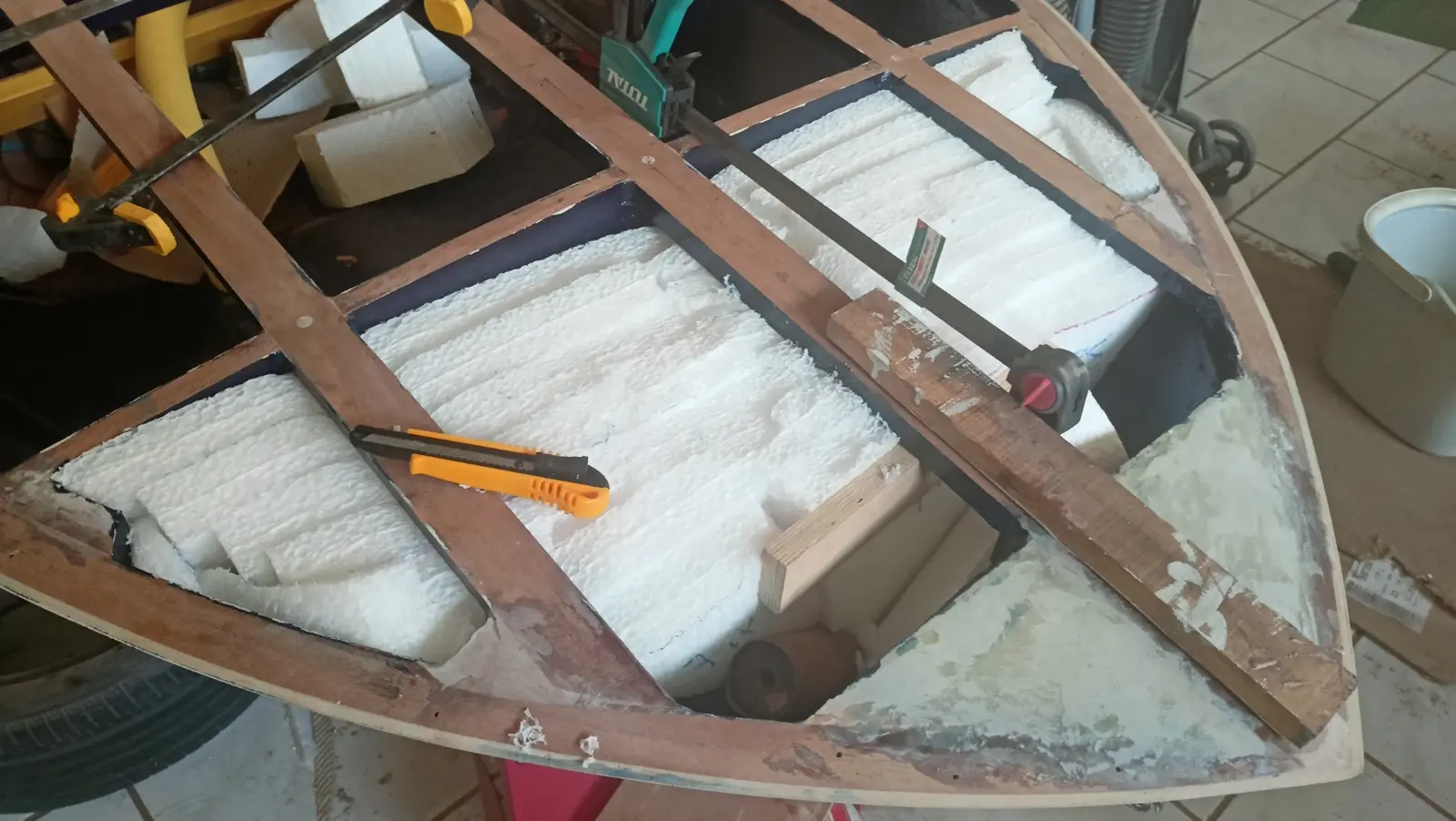
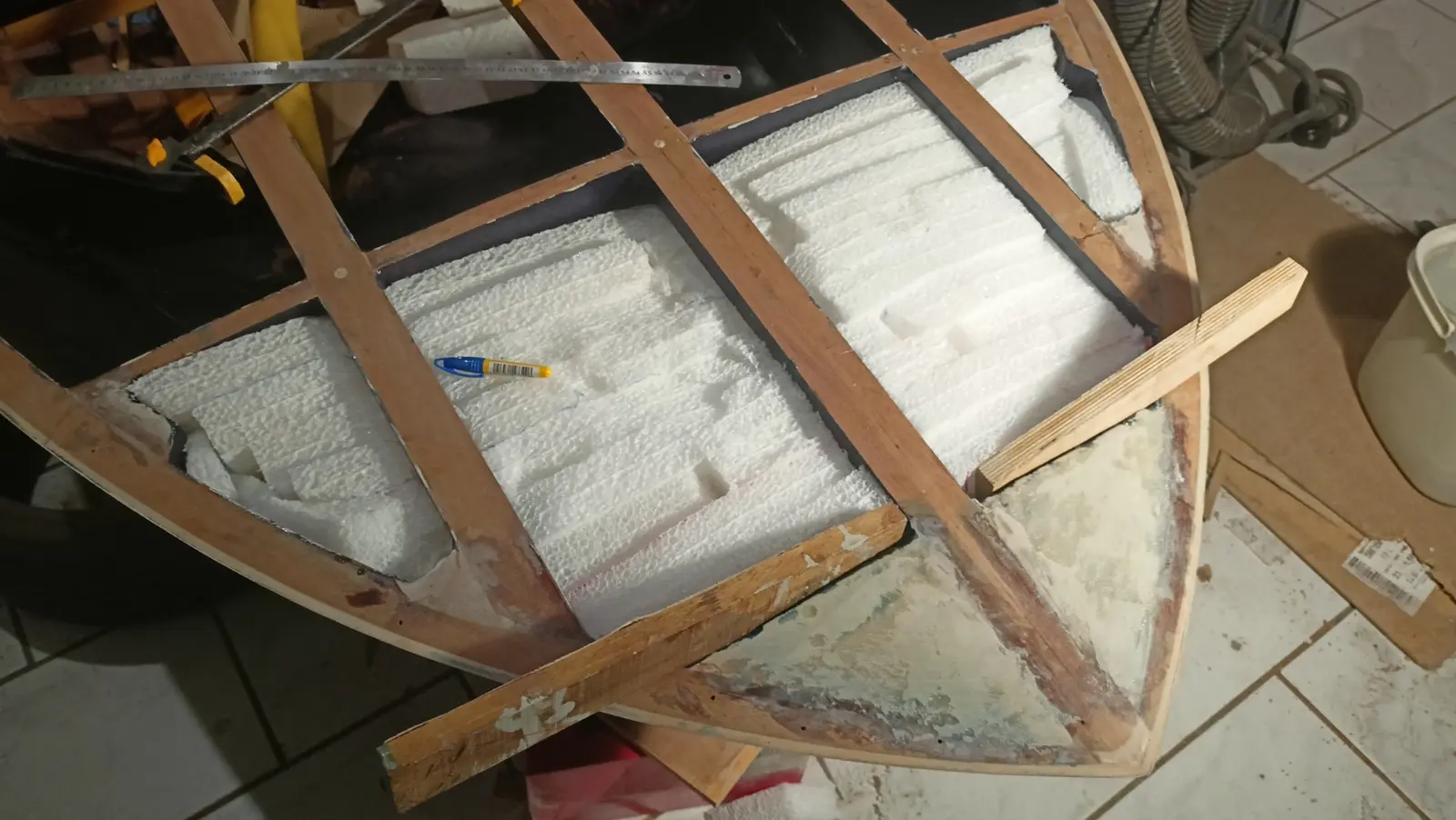
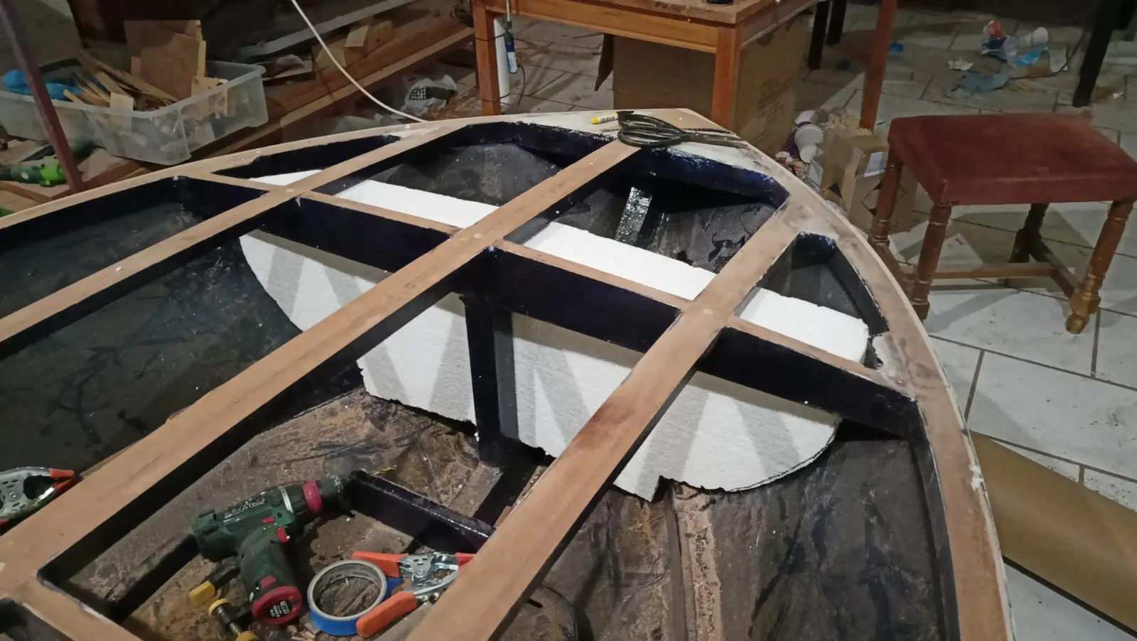
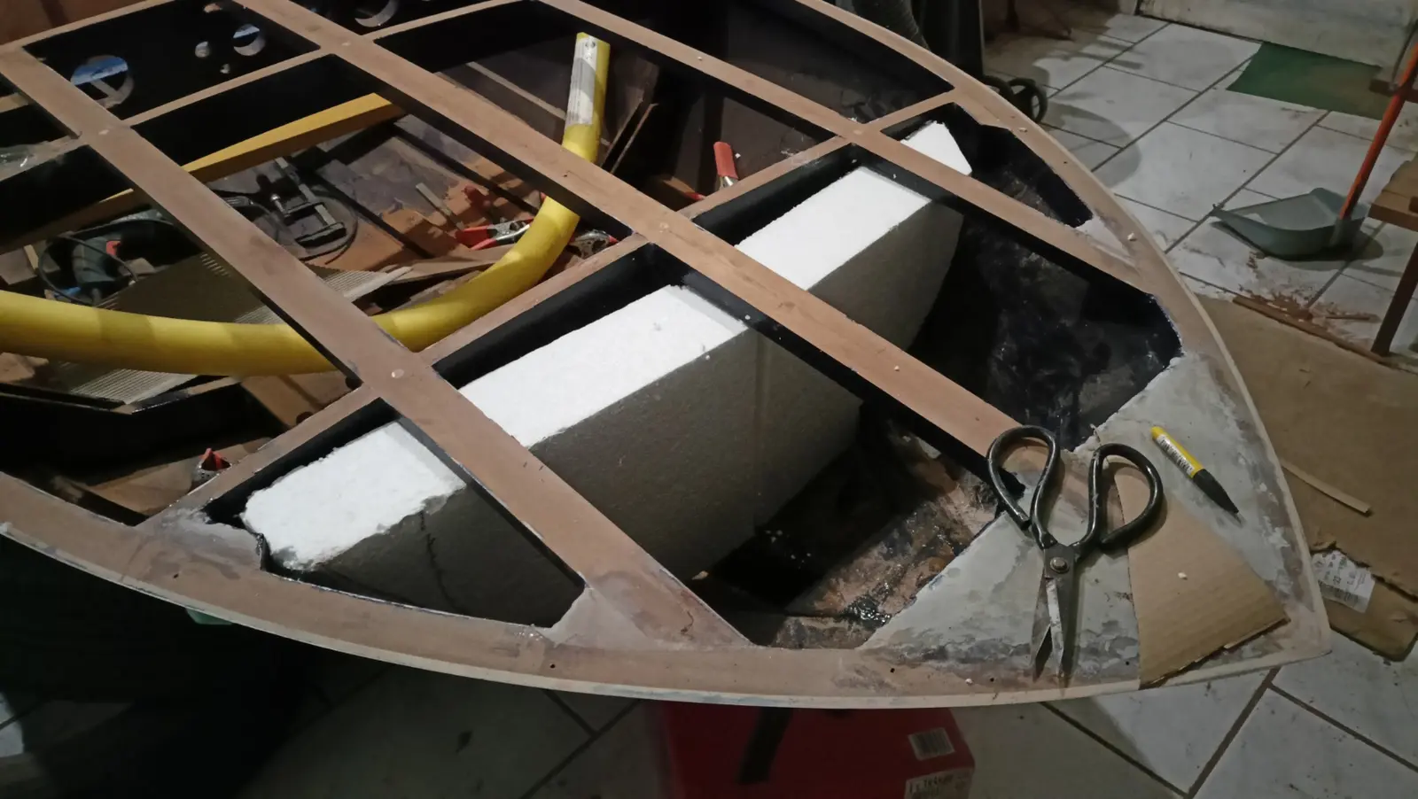
The bow is a sealed and inaccessible space (dead space). Since the next stage of the build is closing that compartment permanently, the polyethylene sheet has to go in before it is decked over.

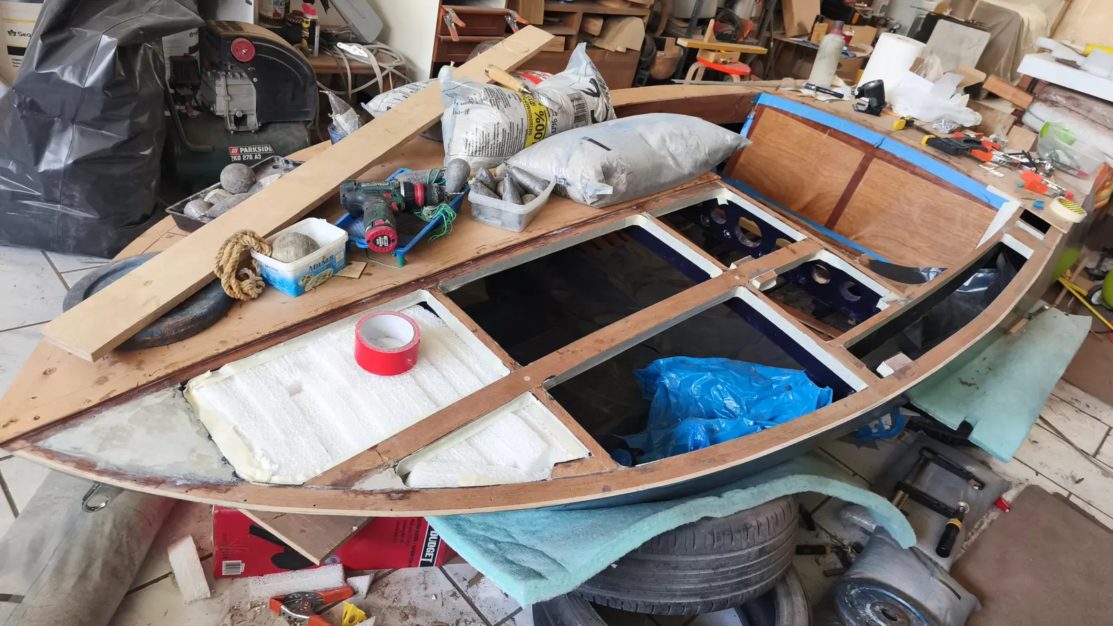
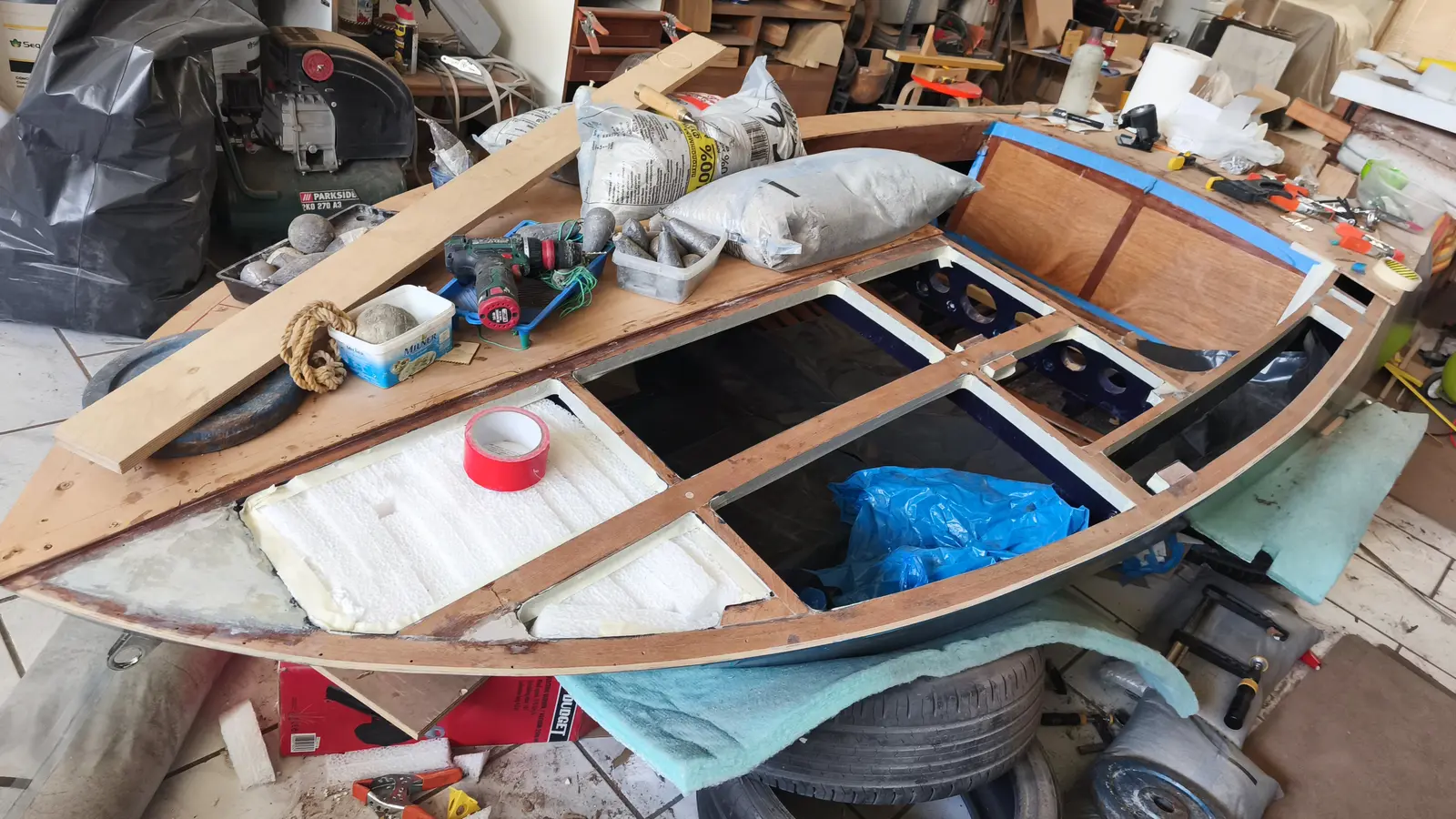
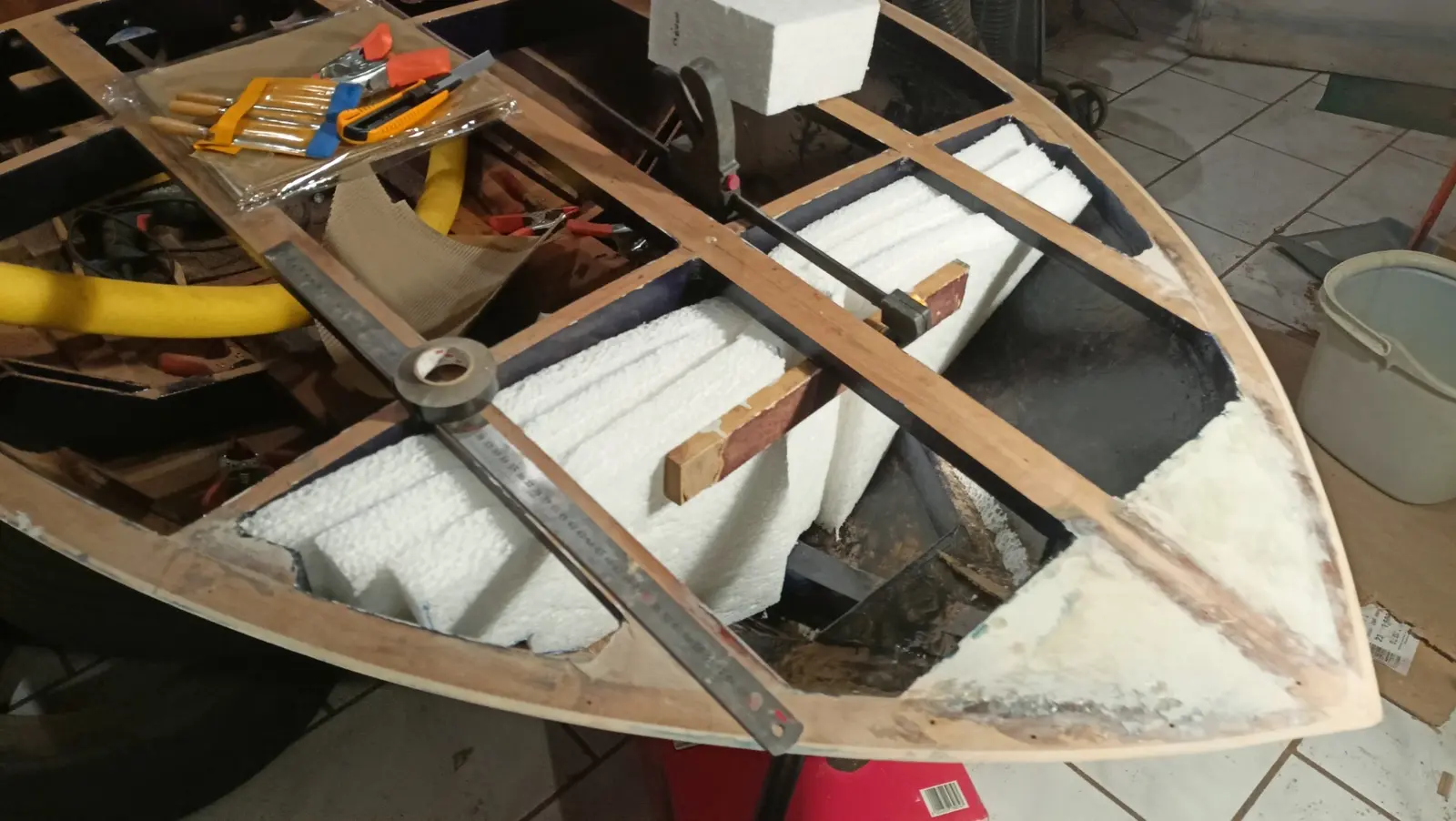
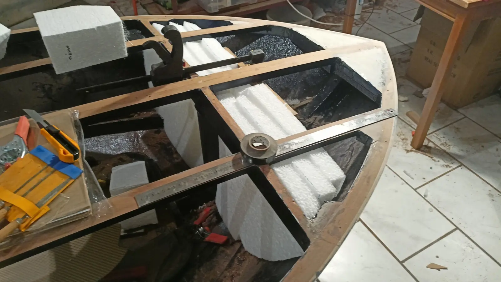
The available space was filled with as much sheet as possible, cut, fitted and wedged in, making sure it stayed put within the sealed volume. I put the sheets in layer by layer and glued them to each other. The result is a solid mass that cannot come out.

Before that, the stainless fitting for the mooring line was installed, because afterwards I will have no access.

Some photographs of the installation.

Phase B, reinforcing the stern

The stern carries most of the static load, mainly because of the outboard. For that reason about 50 to 60% of the total volume of flotation material will be placed either side of the motor well and under the aft benches.

That arrangement limits how far the stern settles in the event of flooding and helps keep the transom above the surface. This work will be done at a later stage of the build.

Phase C, distribution along the sides for stability

To improve transverse stability and reduce the chance of capsize, some of the polyethylene foam will be cut into strips and fitted as high as possible on the side walls of the boat.

That arrangement creates buoyancy at the sides, limits large angles of heel and helps keep the boat as level as possible (level flotation), even when the inside has filled with water.

The side flotation will be fitted once the main joinery work is complete.

Link

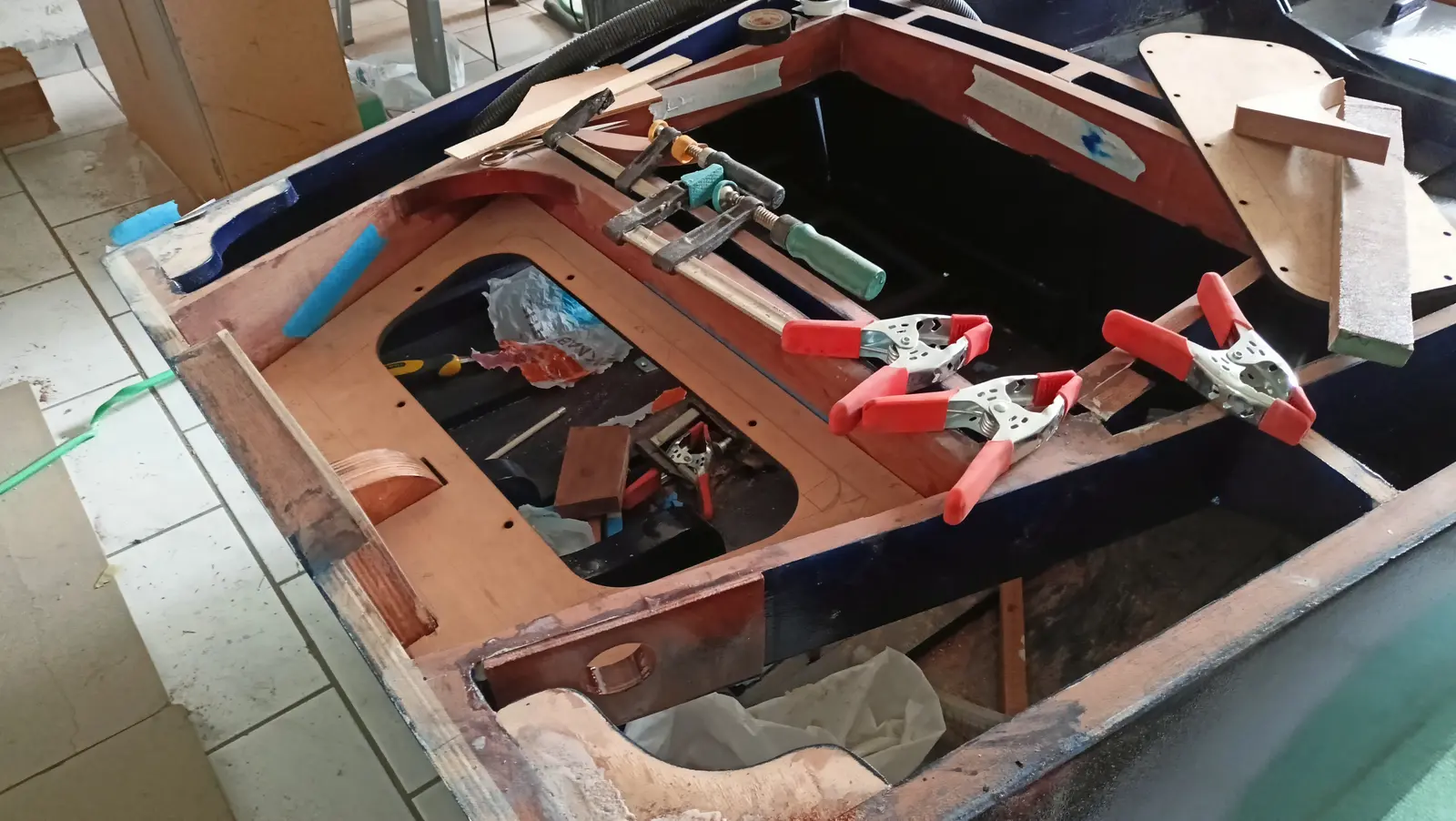
Gluing on the deck plywood

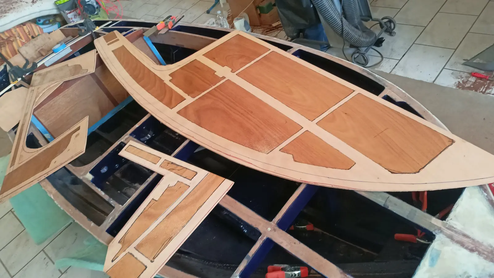
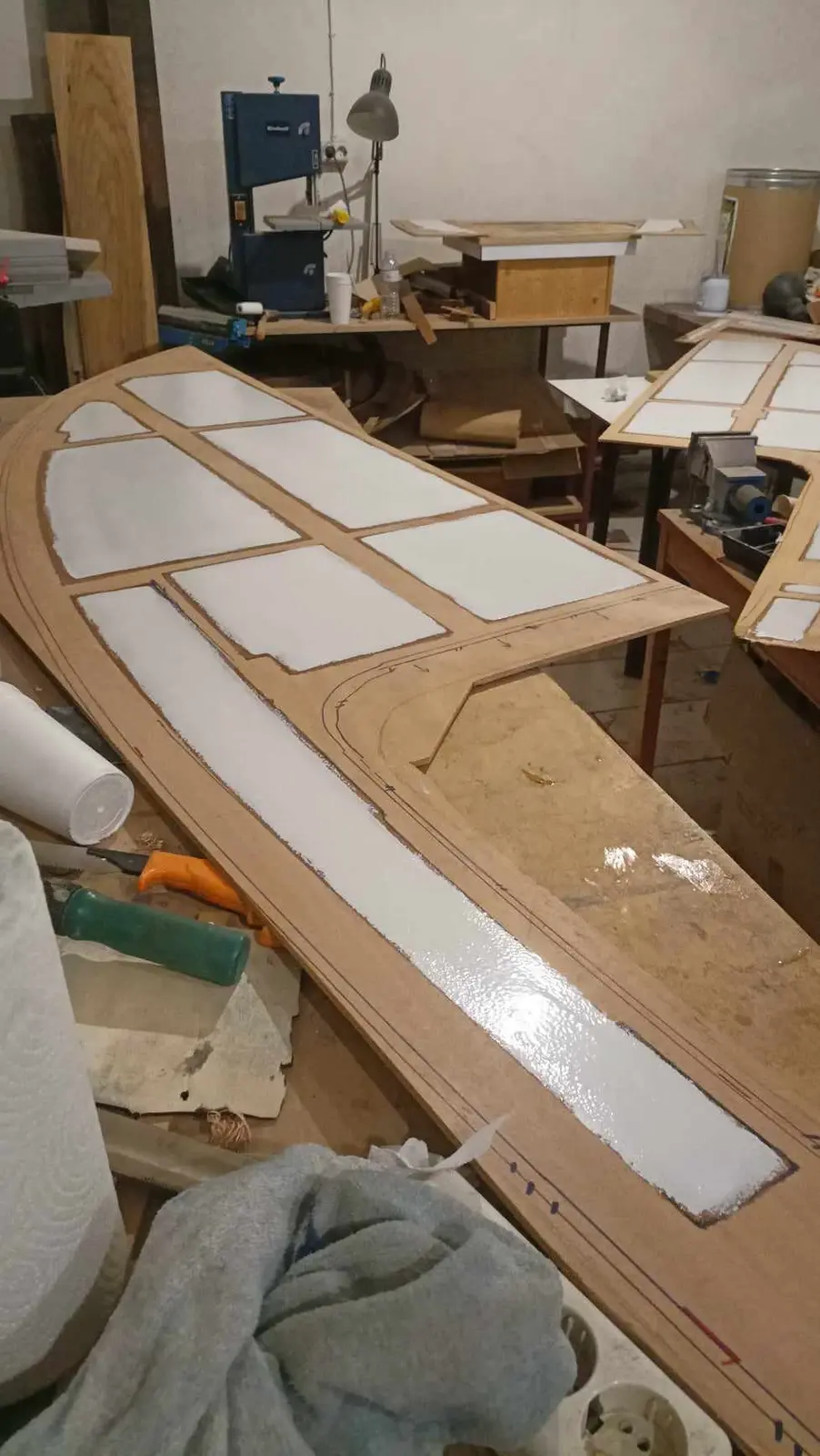
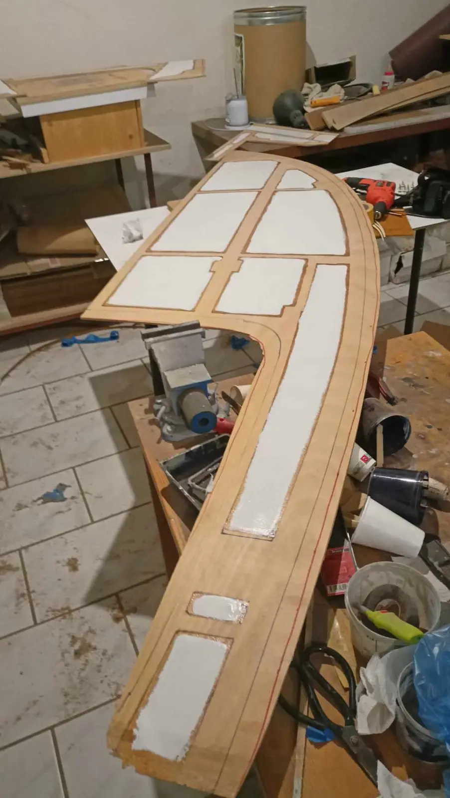
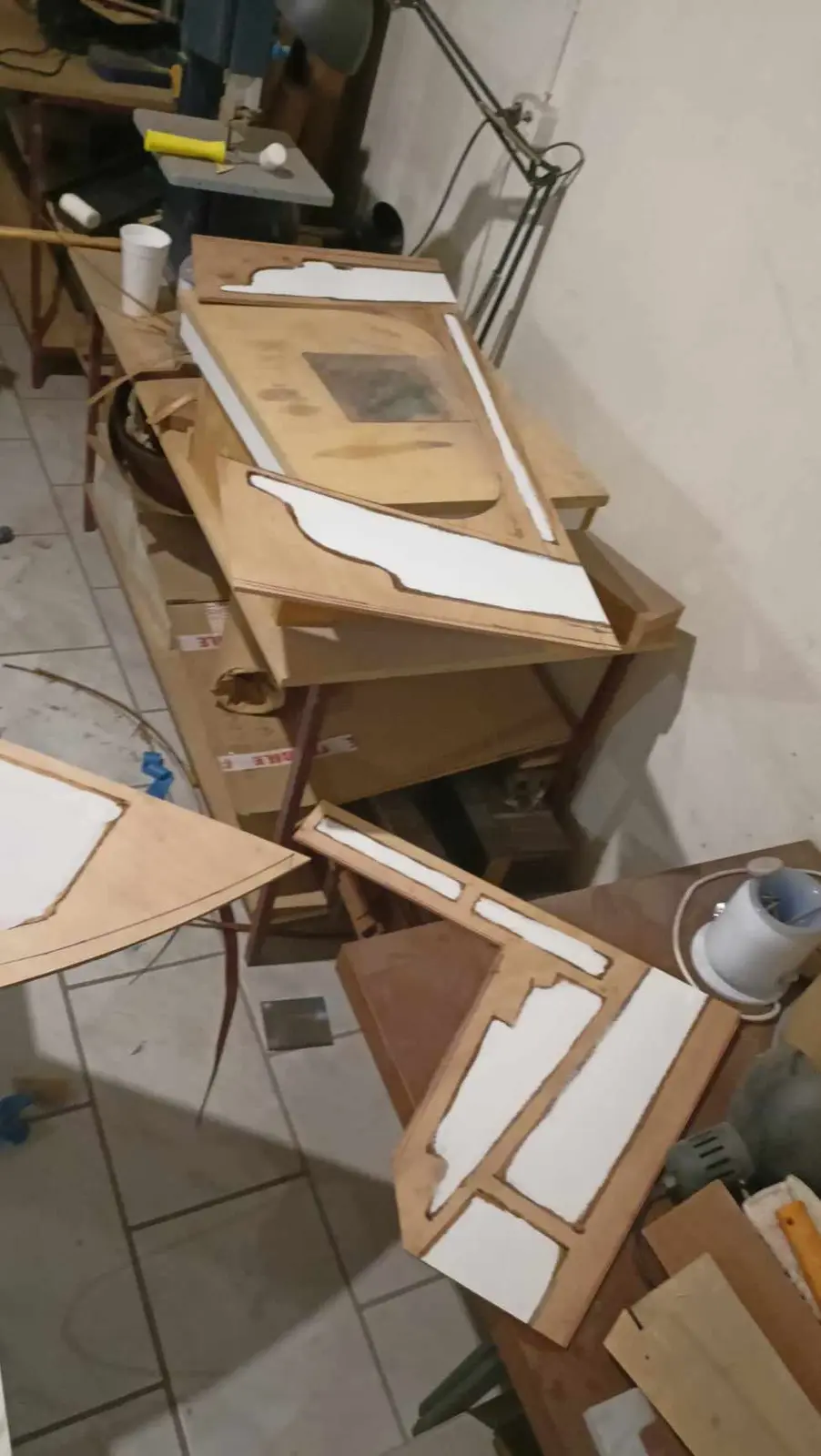
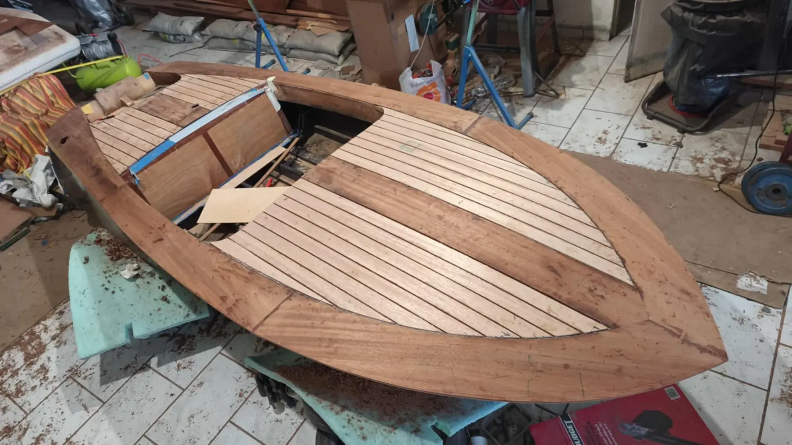
For the deck, 6 mm okoume plywood will be glued on, with solid sipo on top around the outside and American mahogany on the inside.

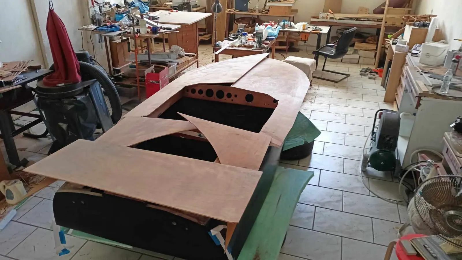
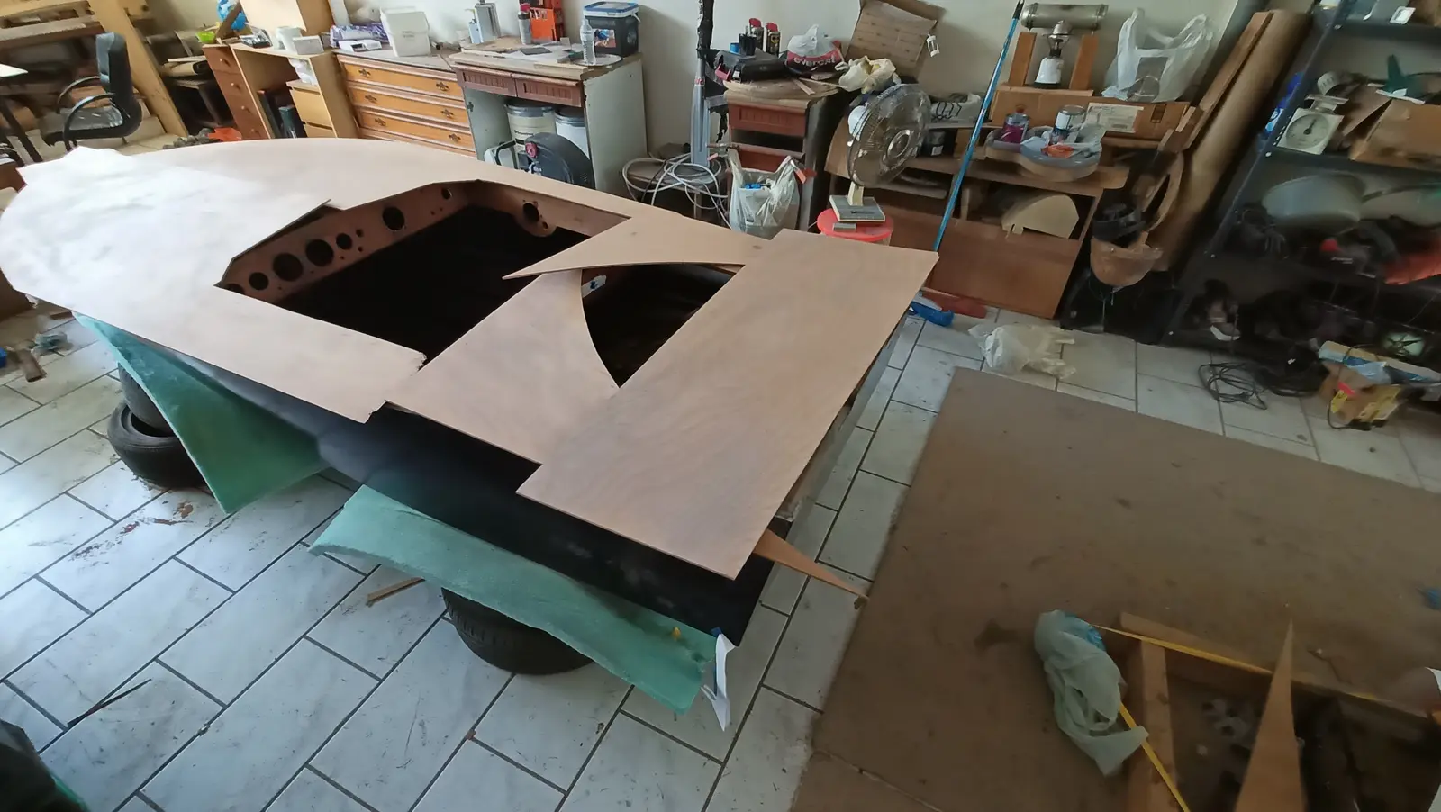
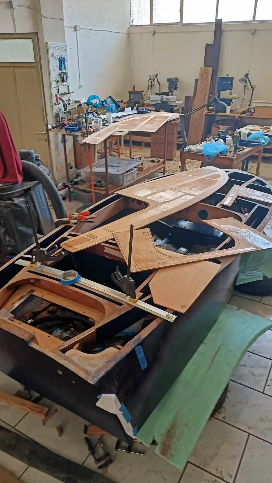
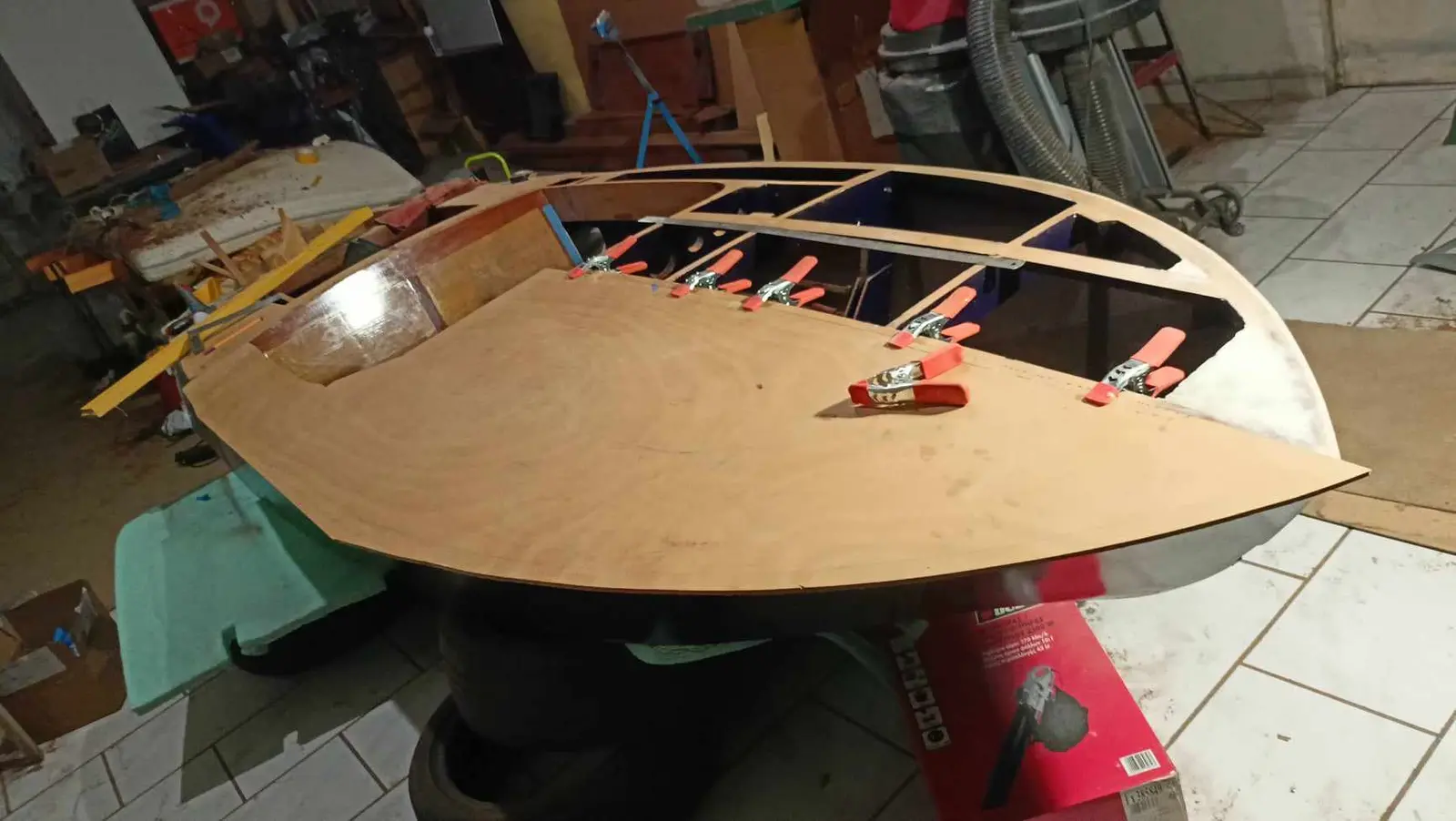
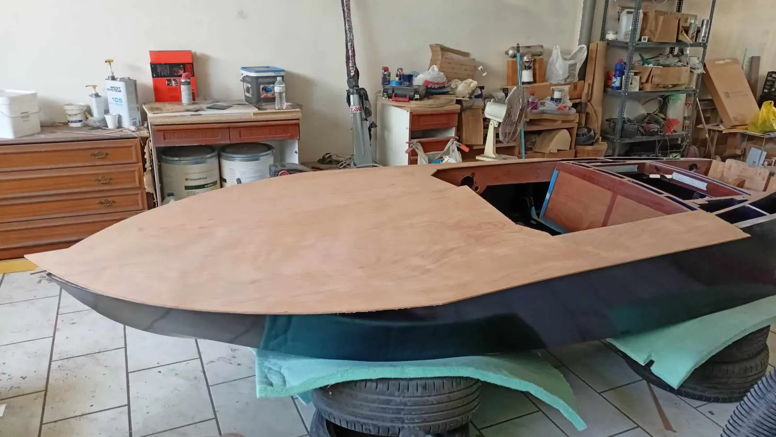
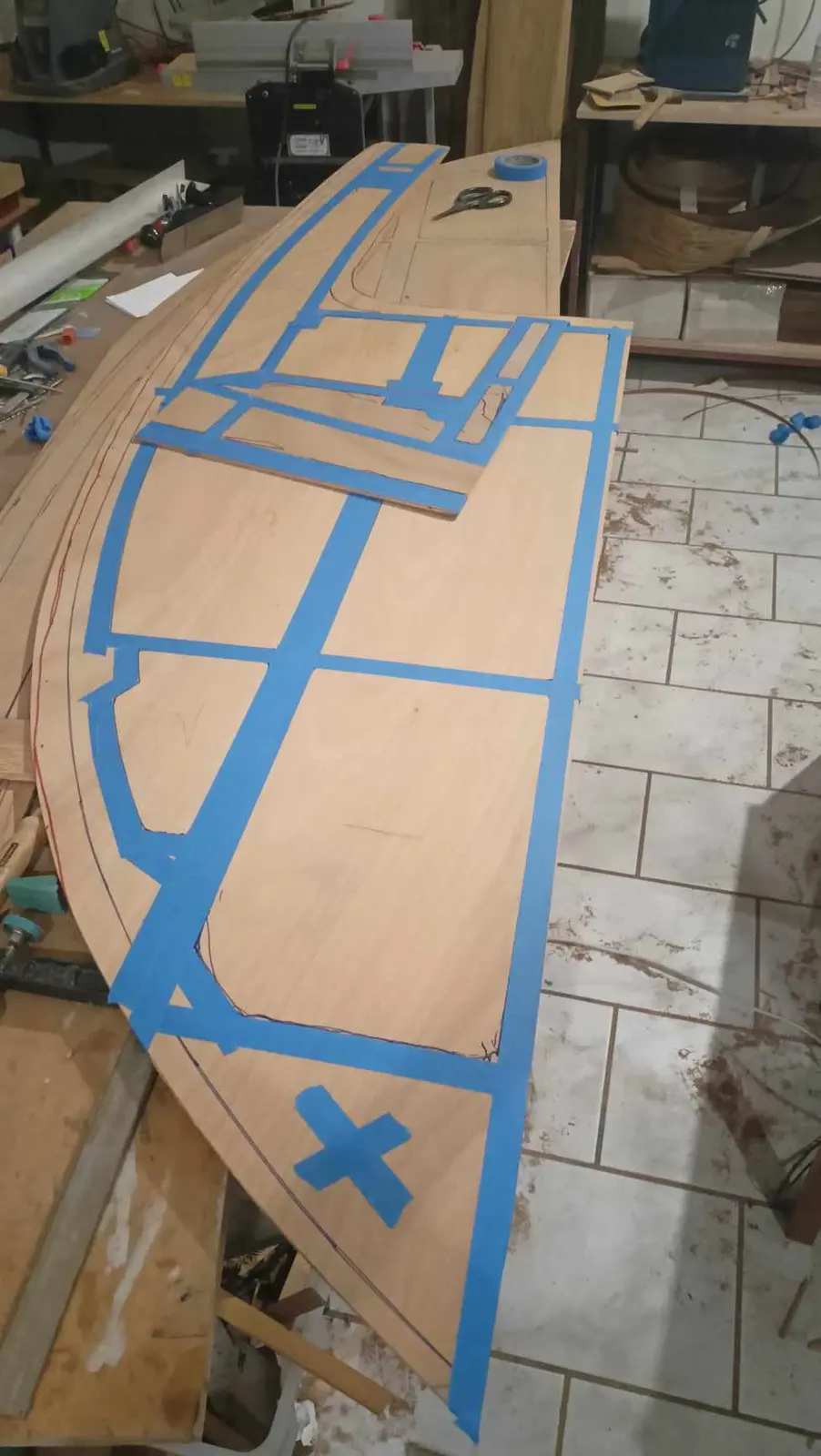
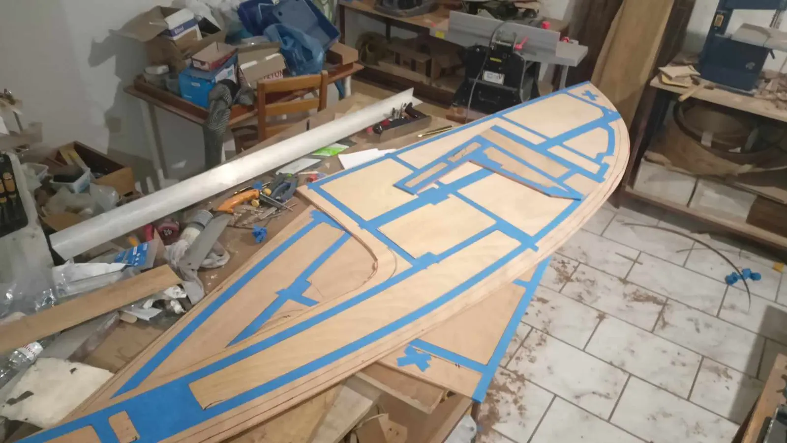
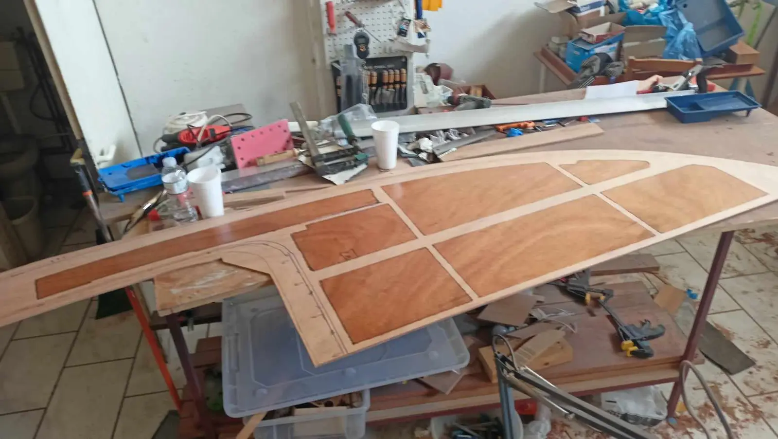
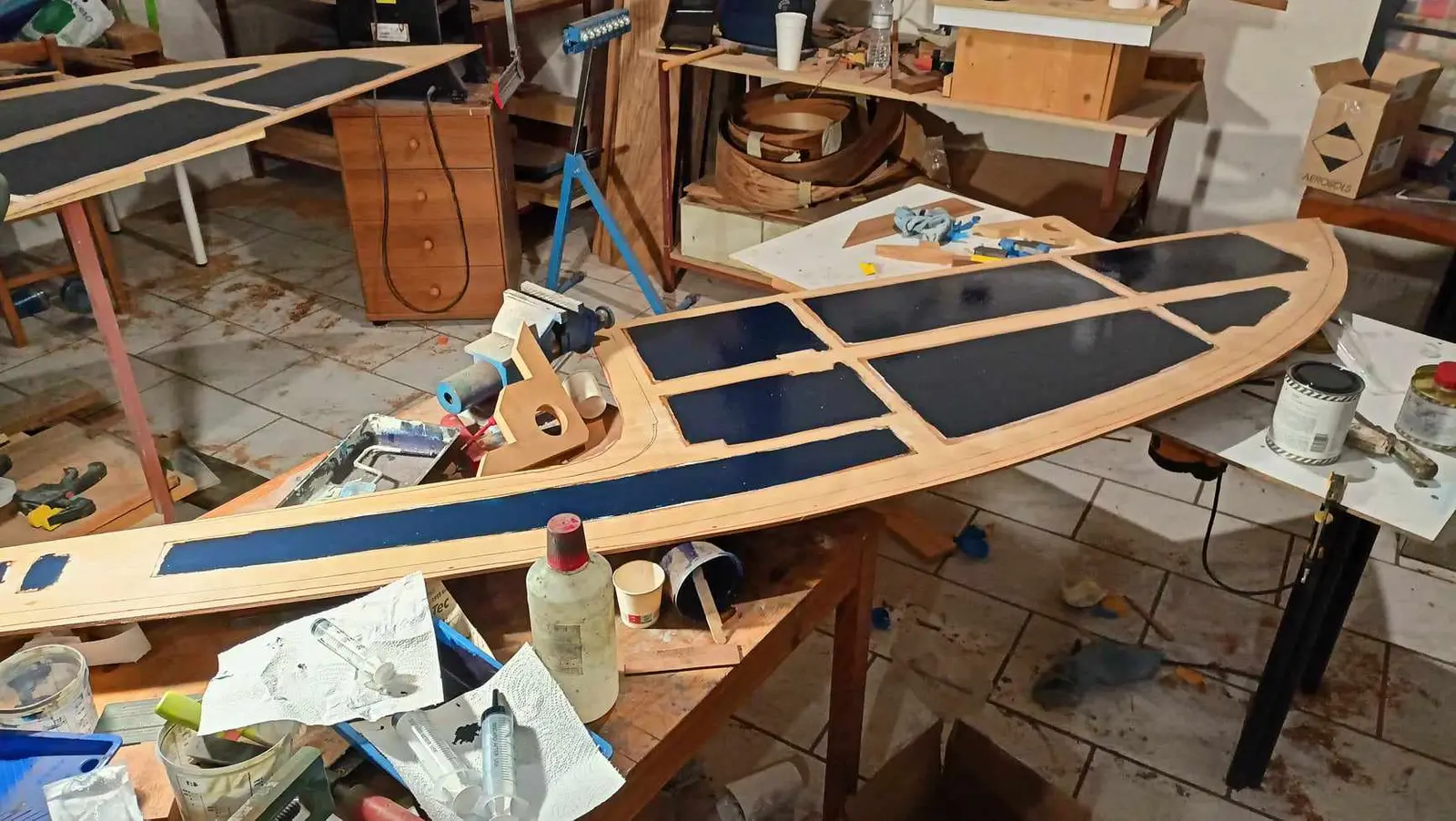
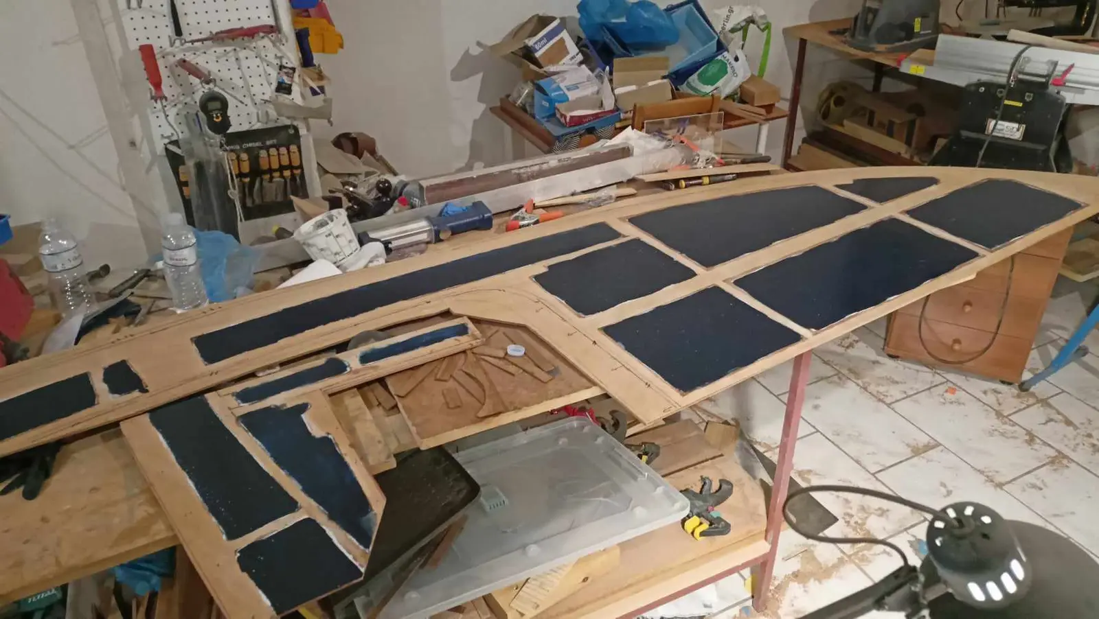
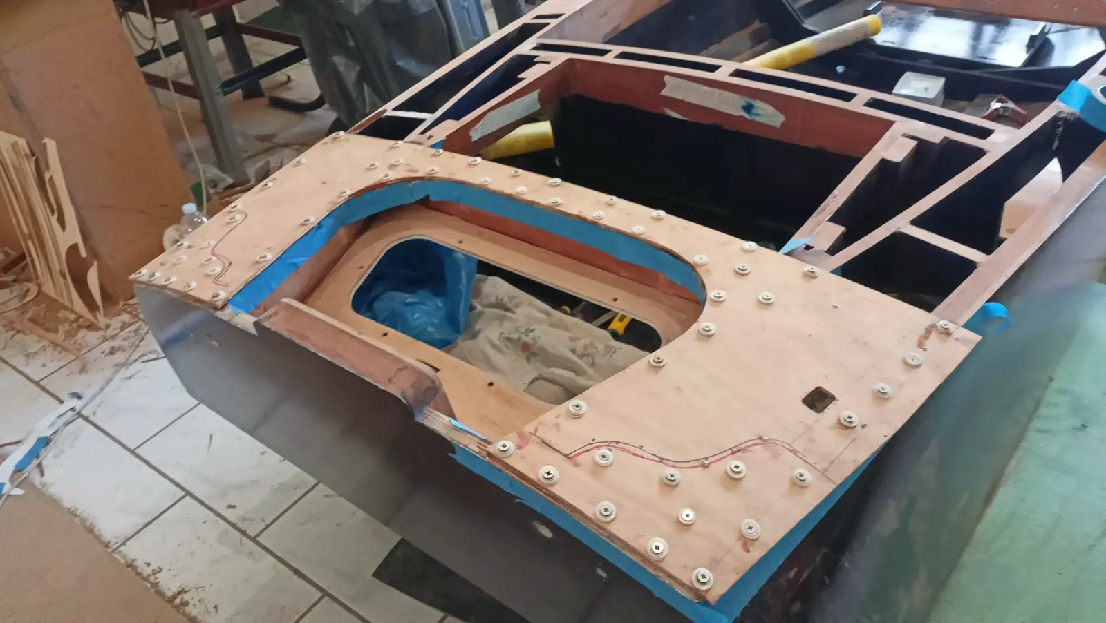
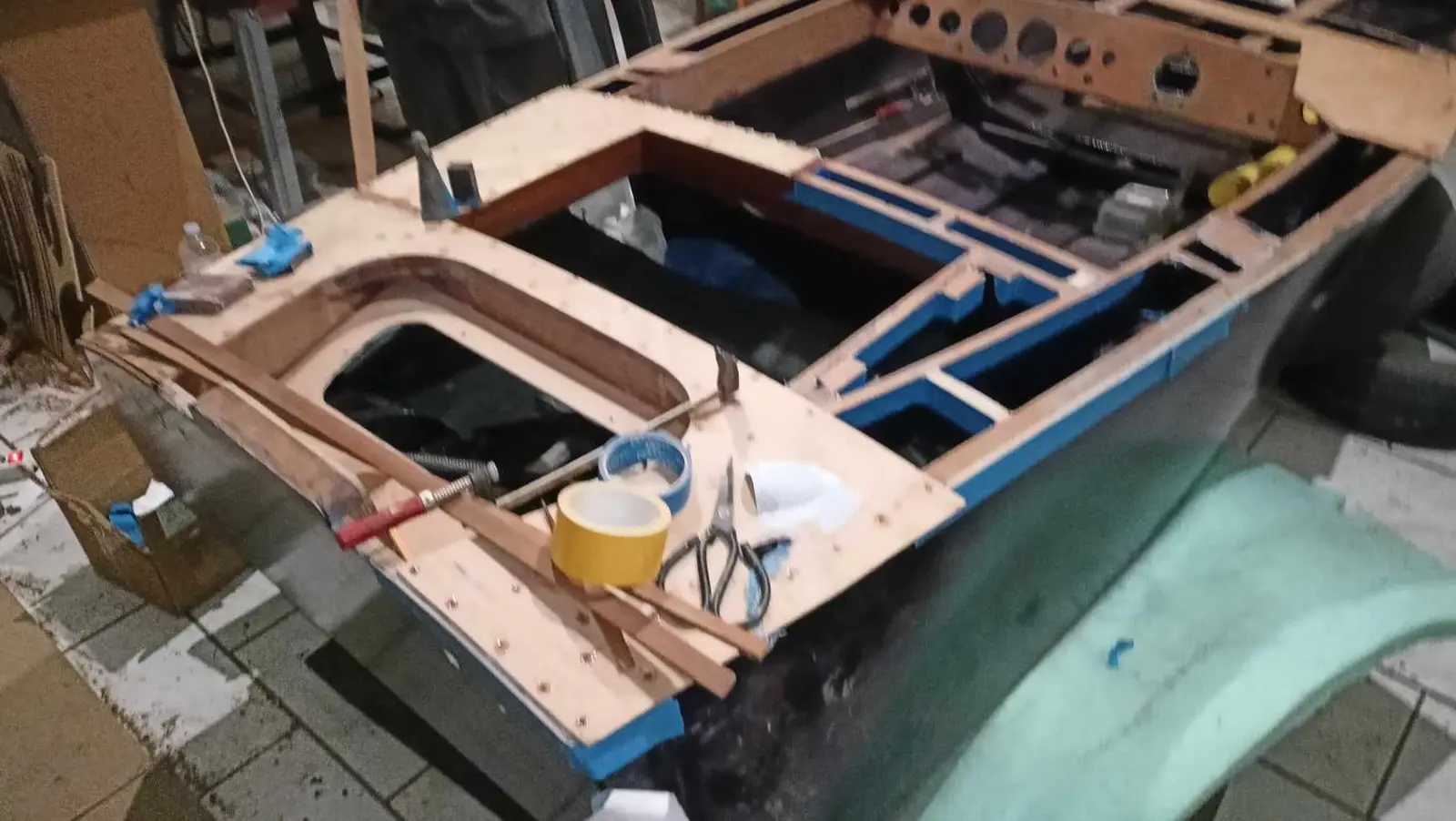
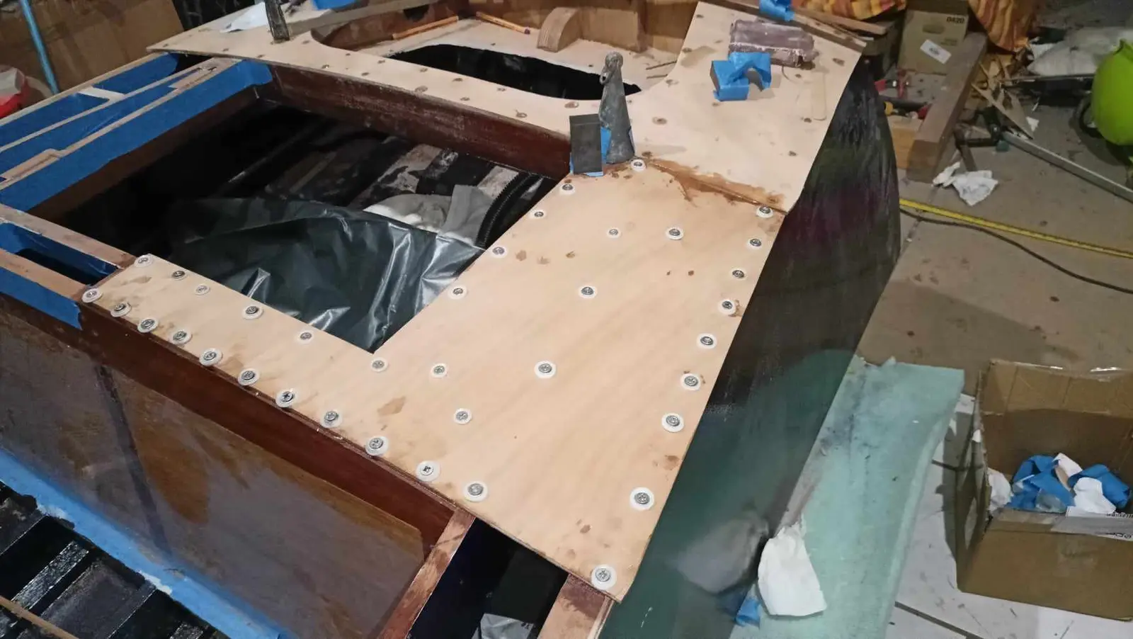
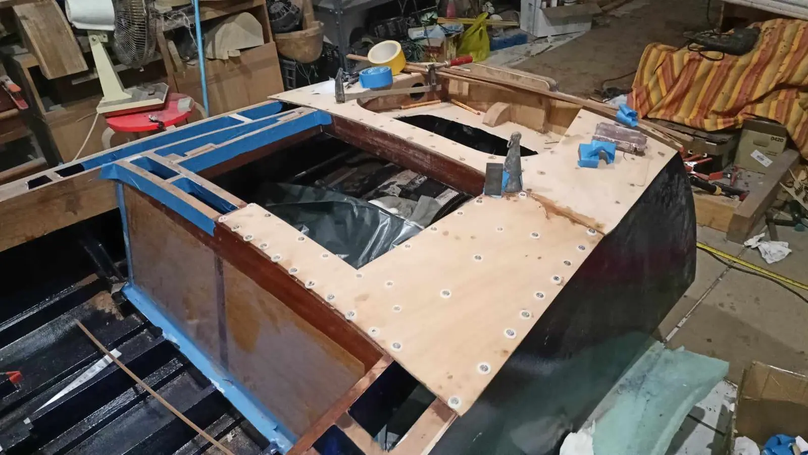
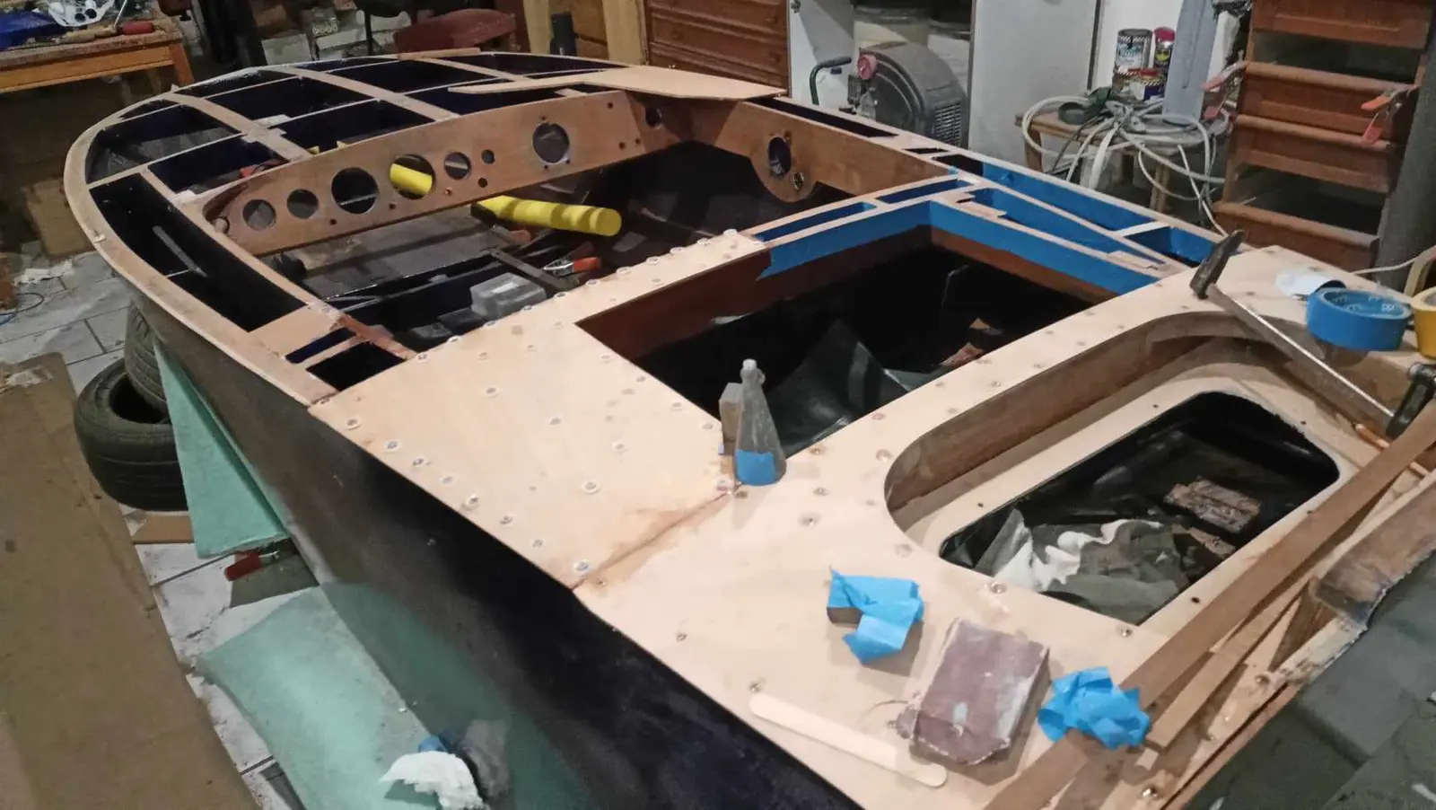
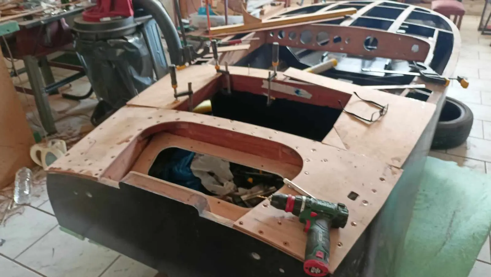
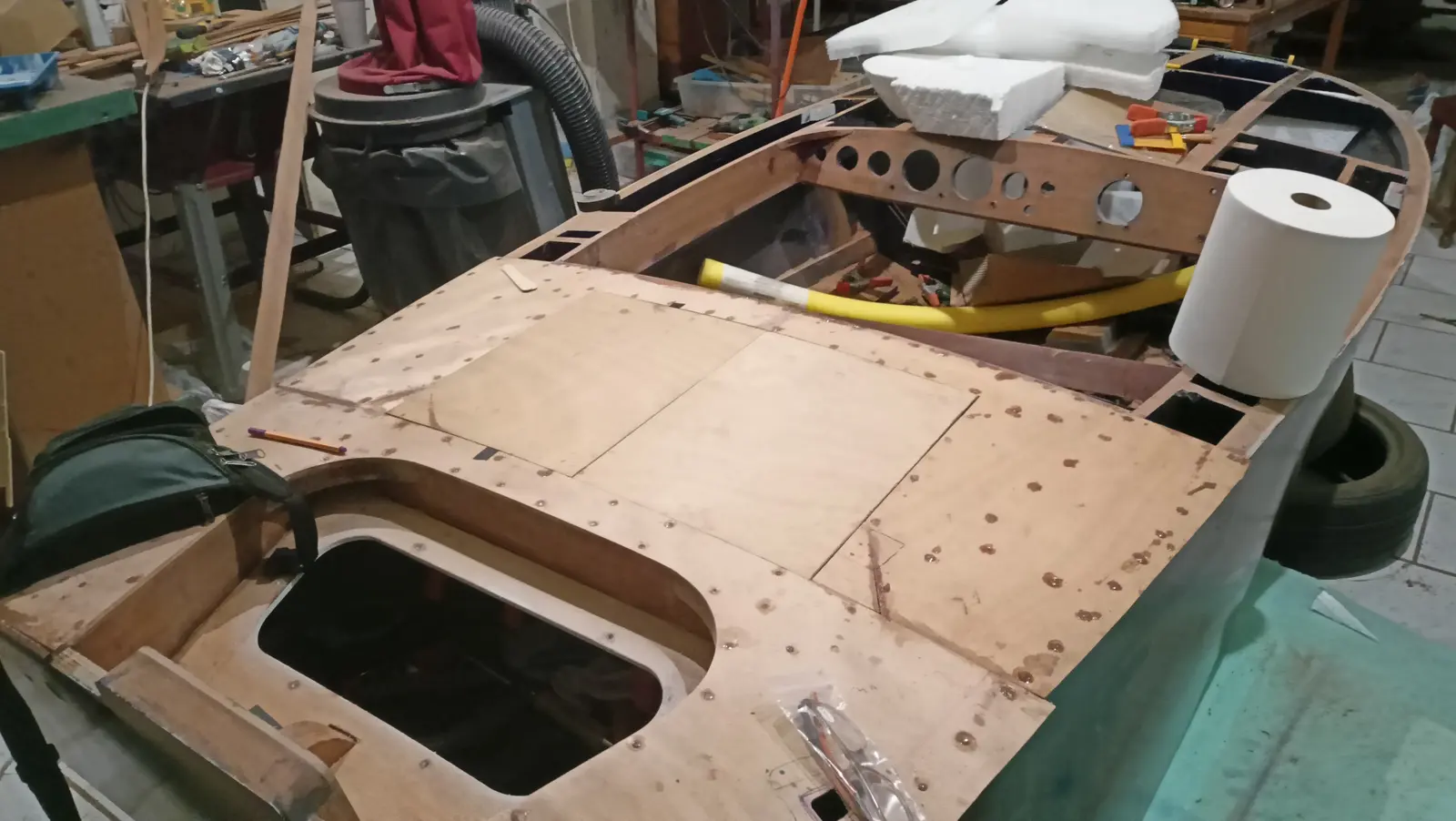
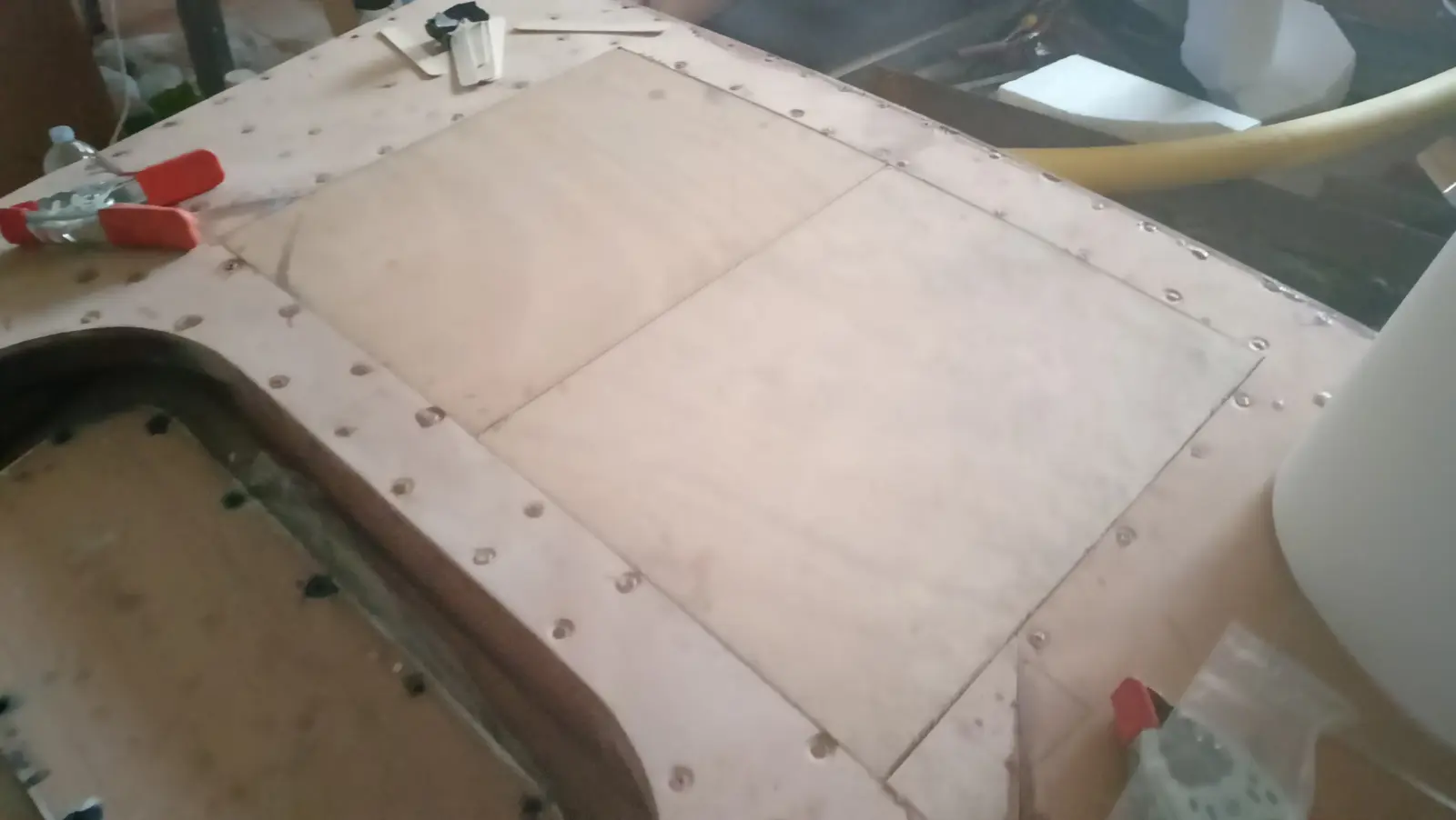
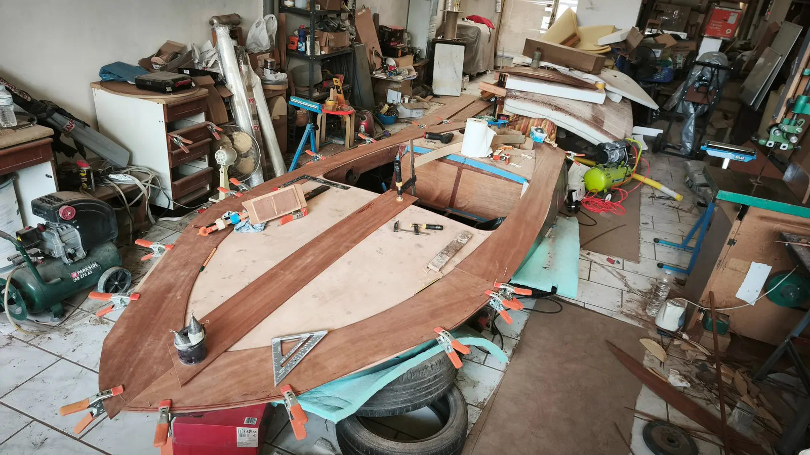
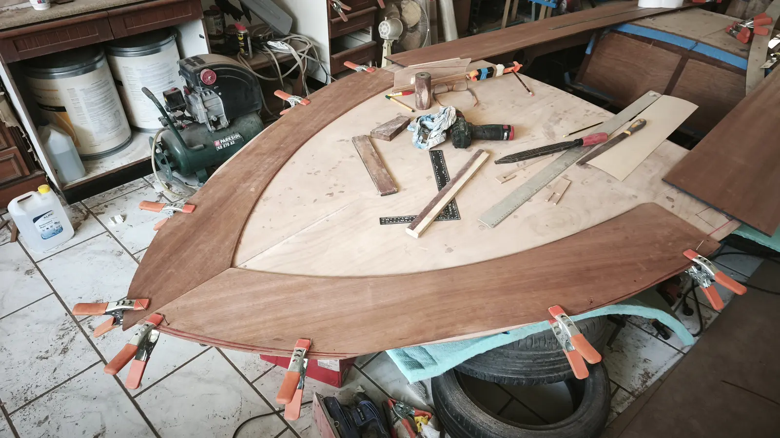
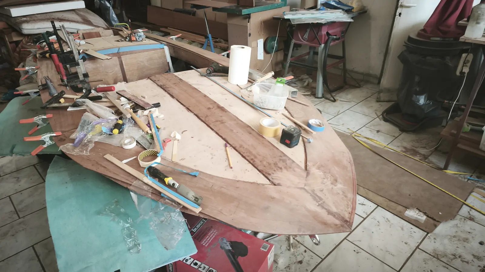
After a good deal of thought, and because the plywood I had was a particular size given the cuts I had already made, I decided to use 5 pieces. One aft, two in the middle (left and right) and two large ones forward.

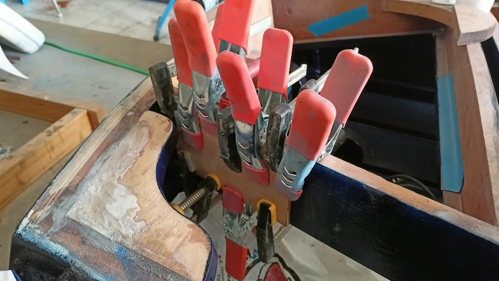
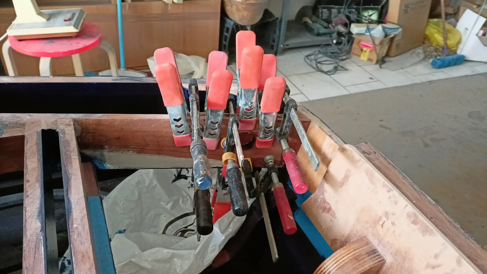
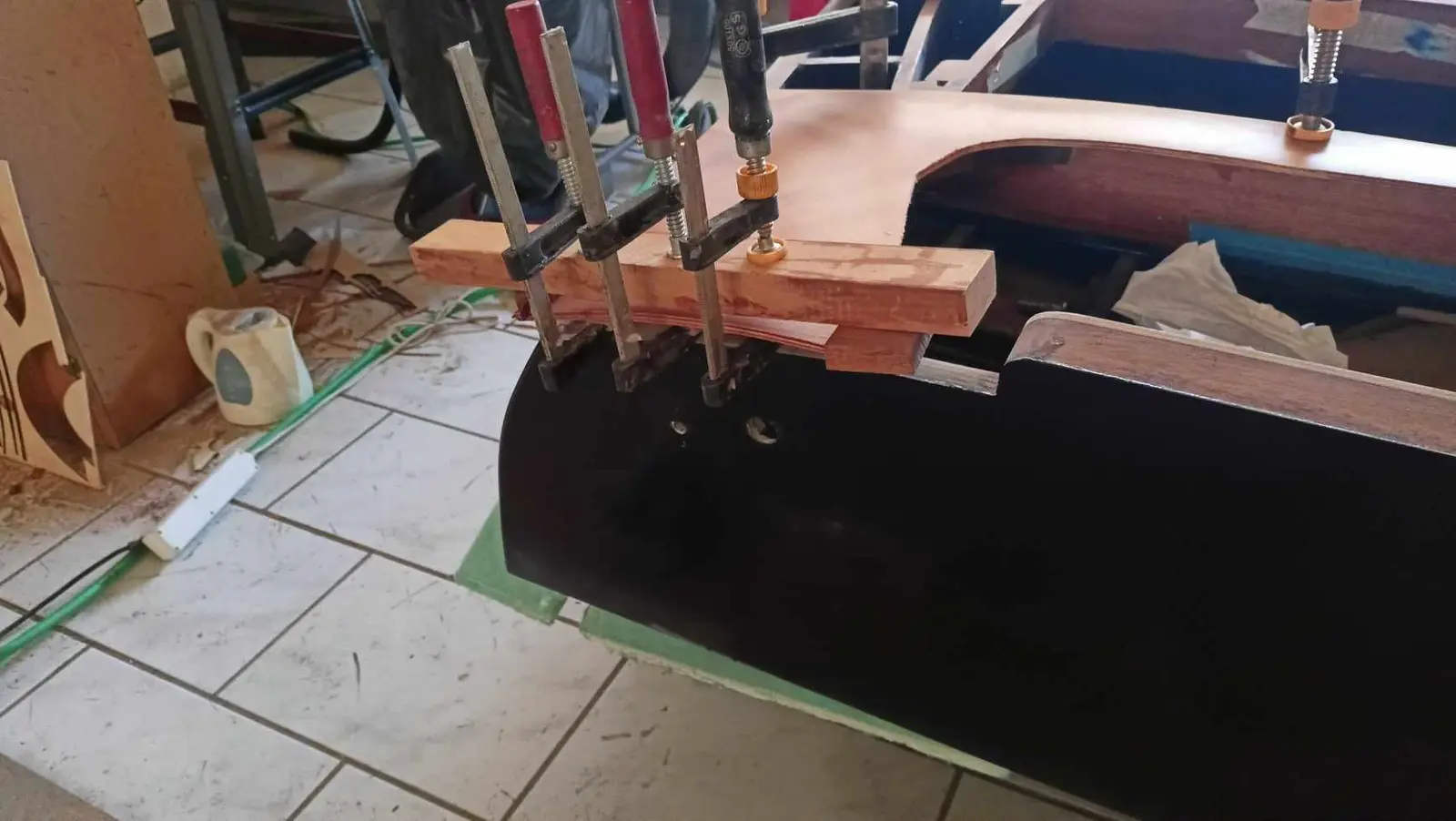
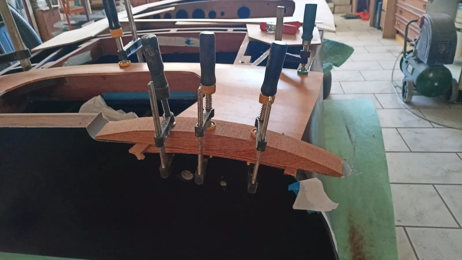
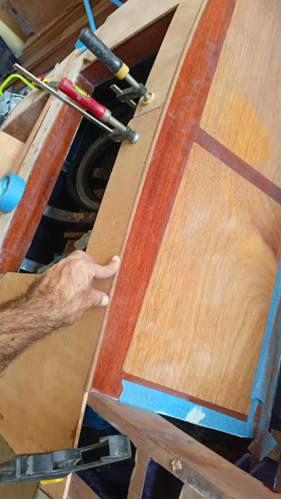
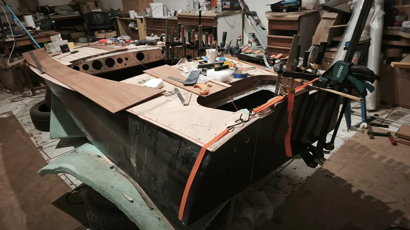
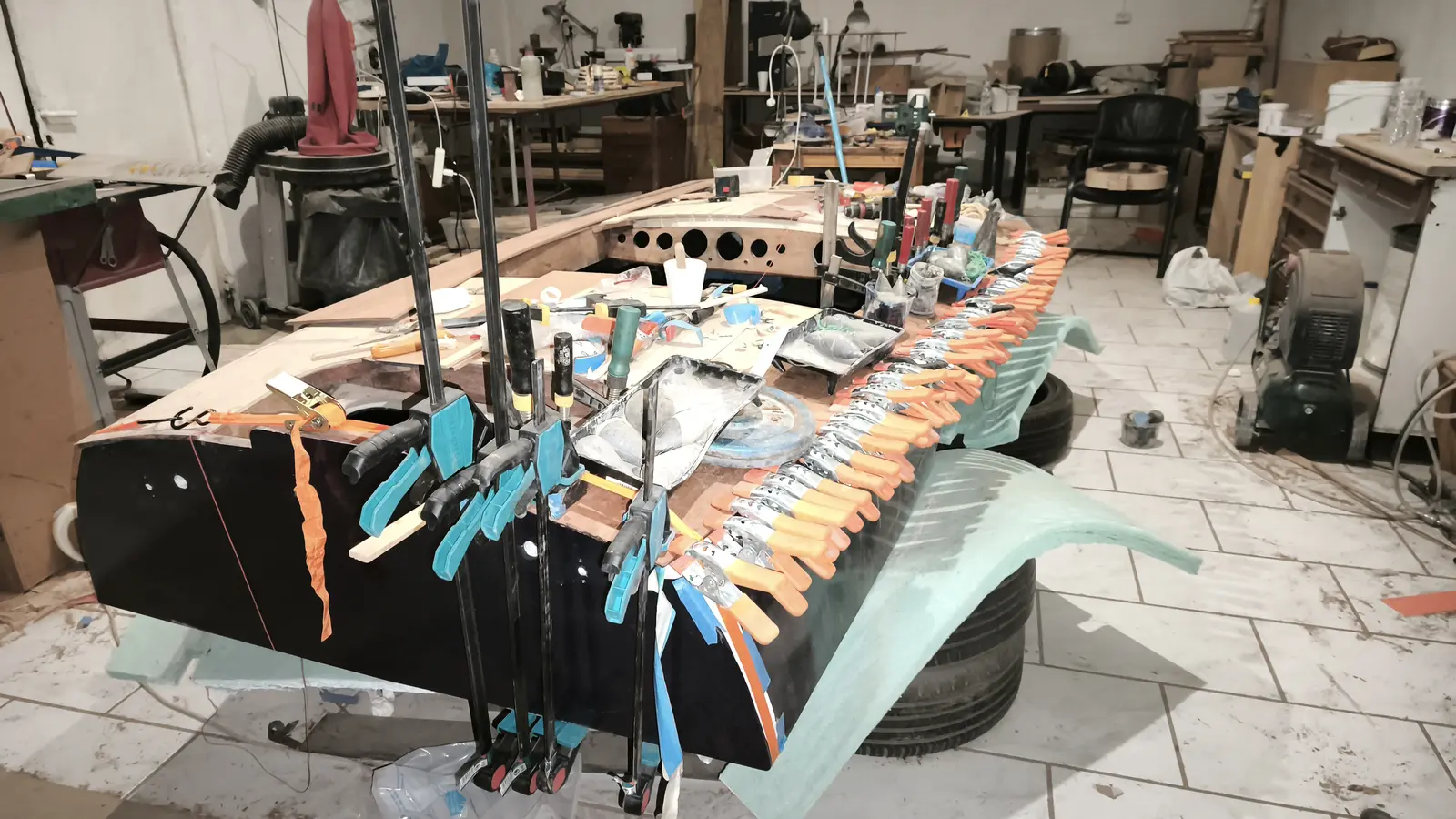
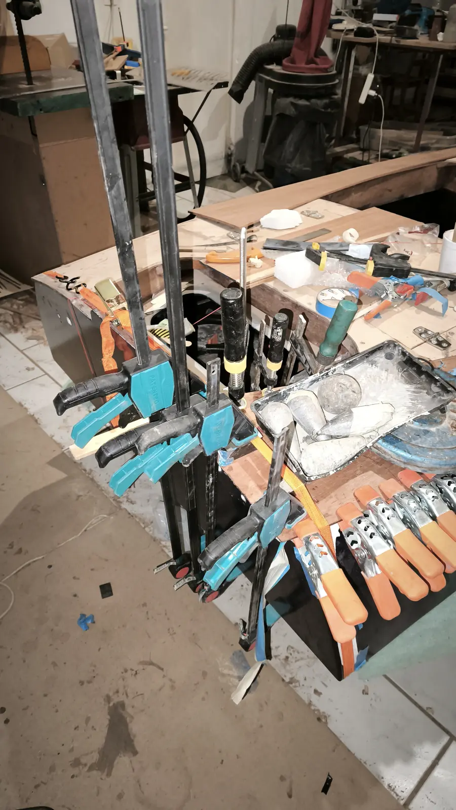
The pieces were cut roughly to the dimensions I wanted. At the aft end I used clamps to press the plywood into the curve.

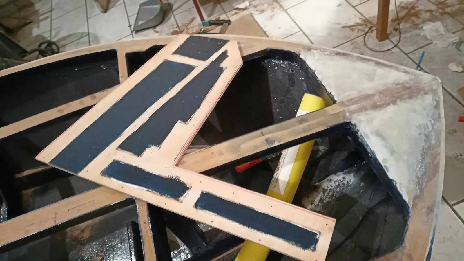
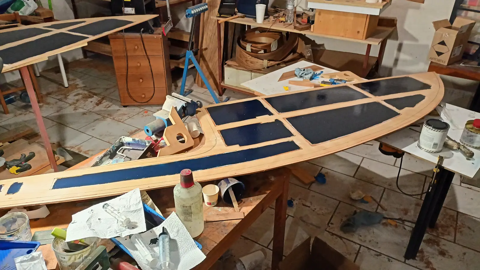
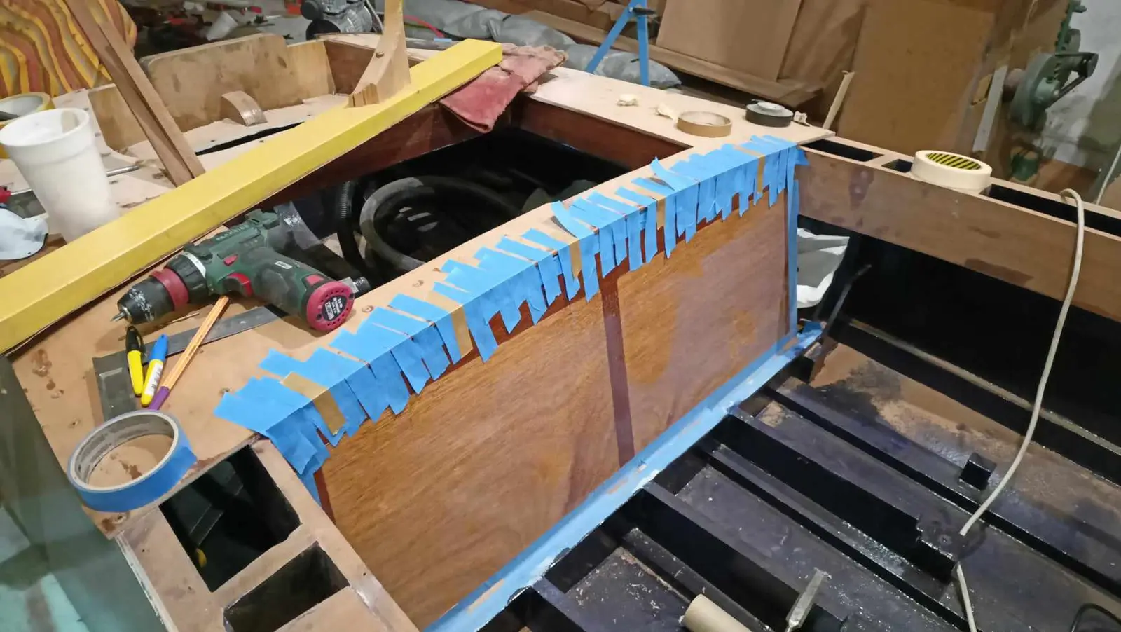
Once they were clamped I marked from underneath the areas that would be glued, so I could coat the rest with resin, primer and paint for protection.

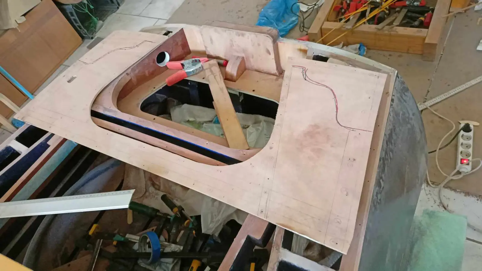
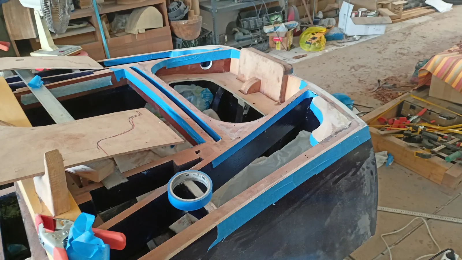
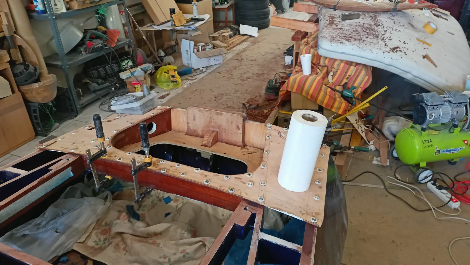
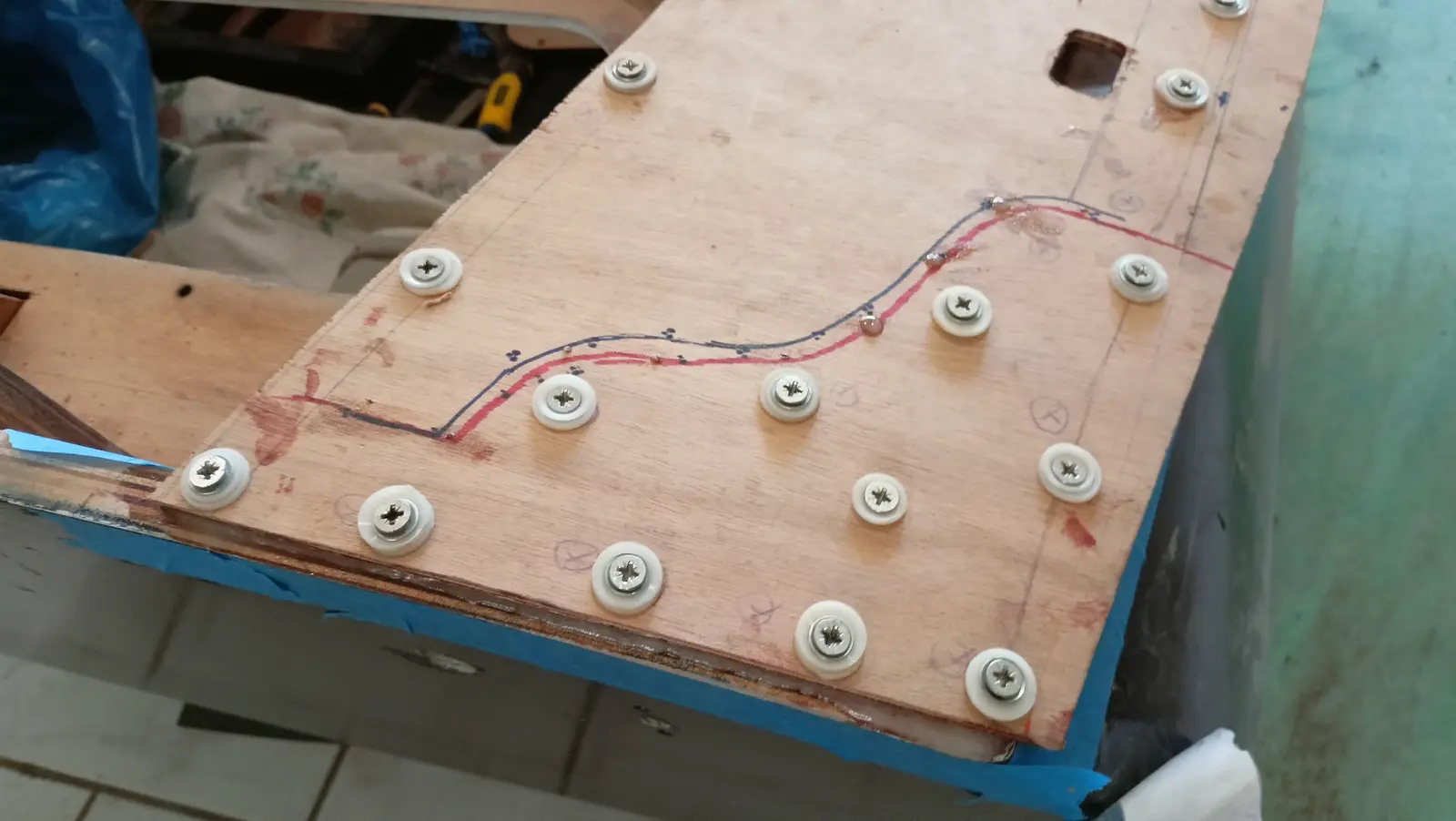
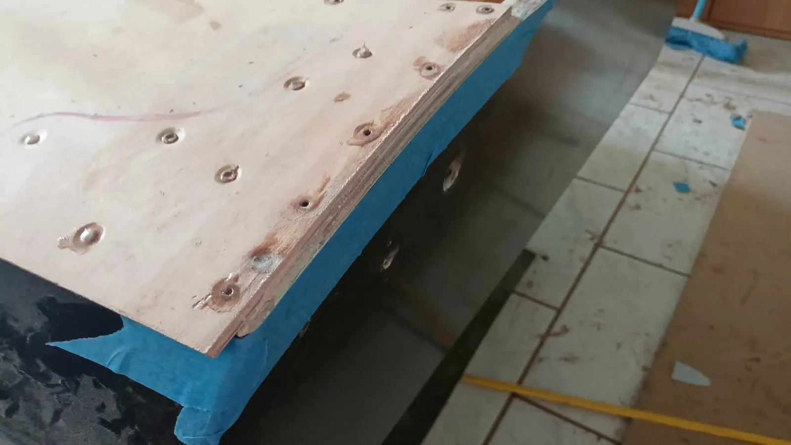
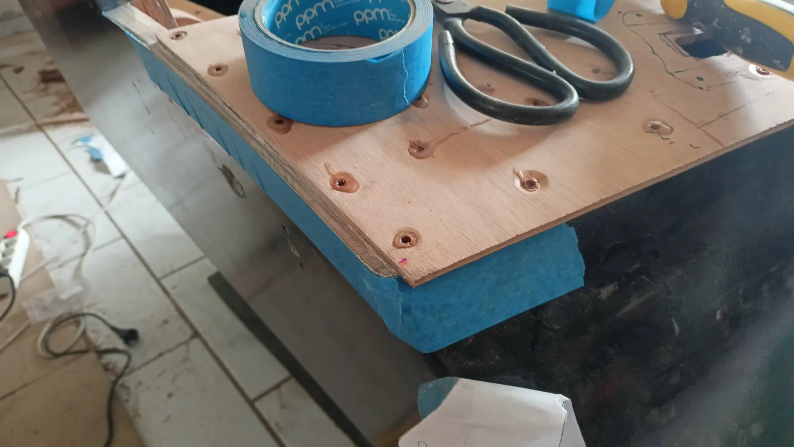
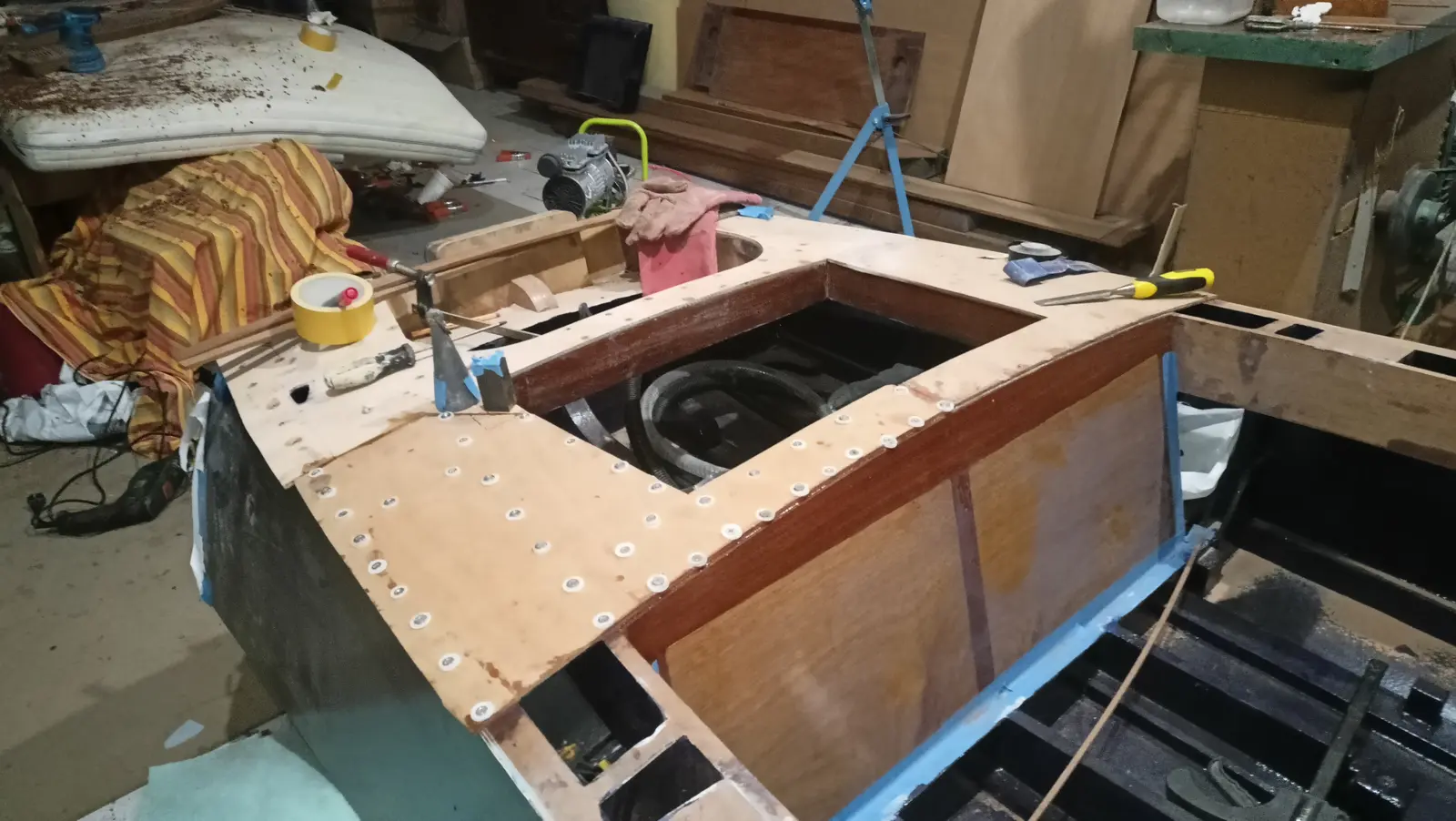
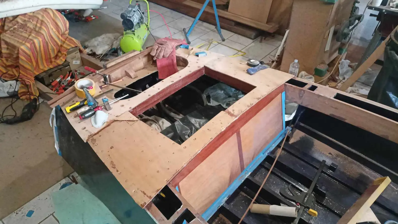
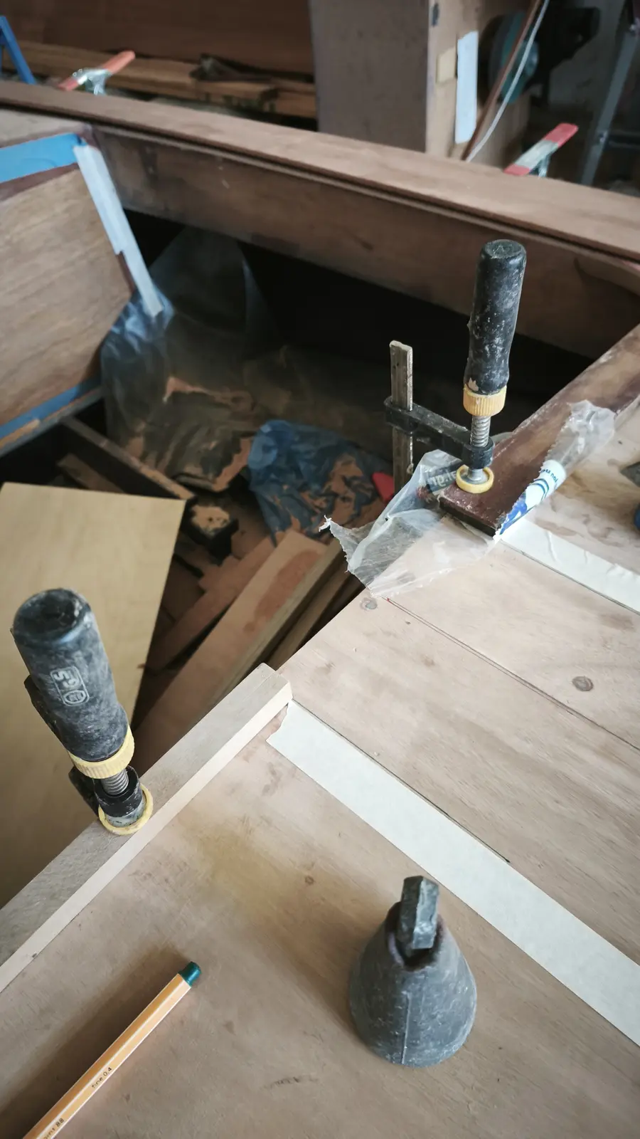
I started gluing at the aft end. It was clamped in its exact position and small holes were drilled with a 2 mm bit at a number of points. Then masking tape went on so glue would not run, and the glue was spread on the areas to be bonded. I had very carefully transferred the glue areas to the top face so I knew where the screws would go.

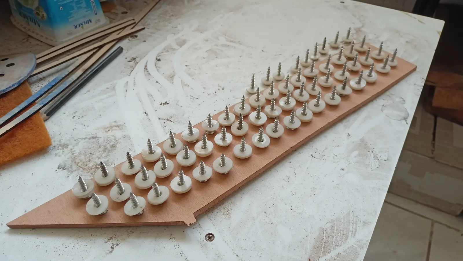
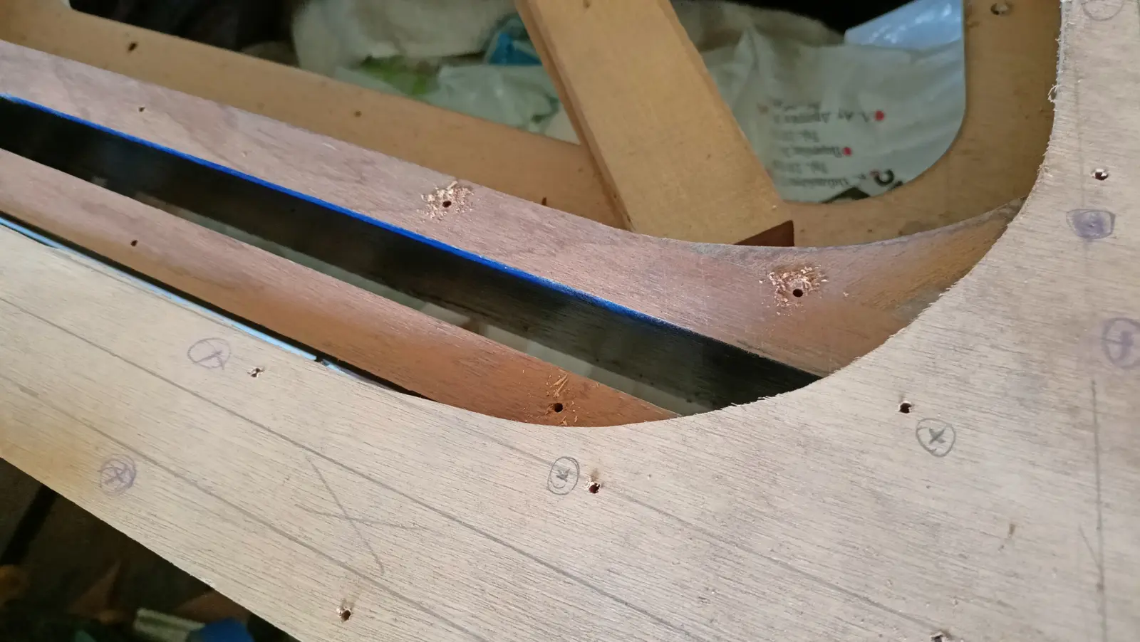
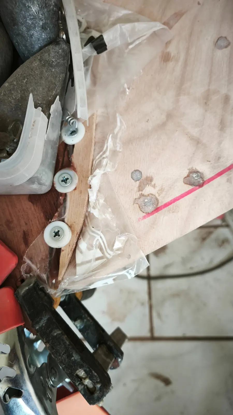
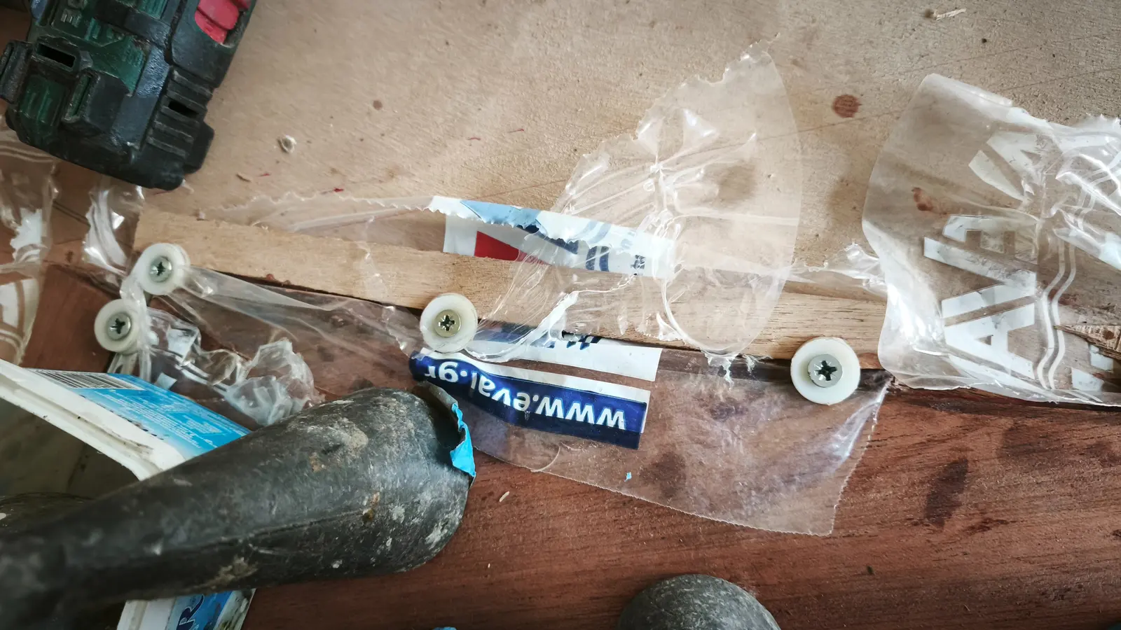
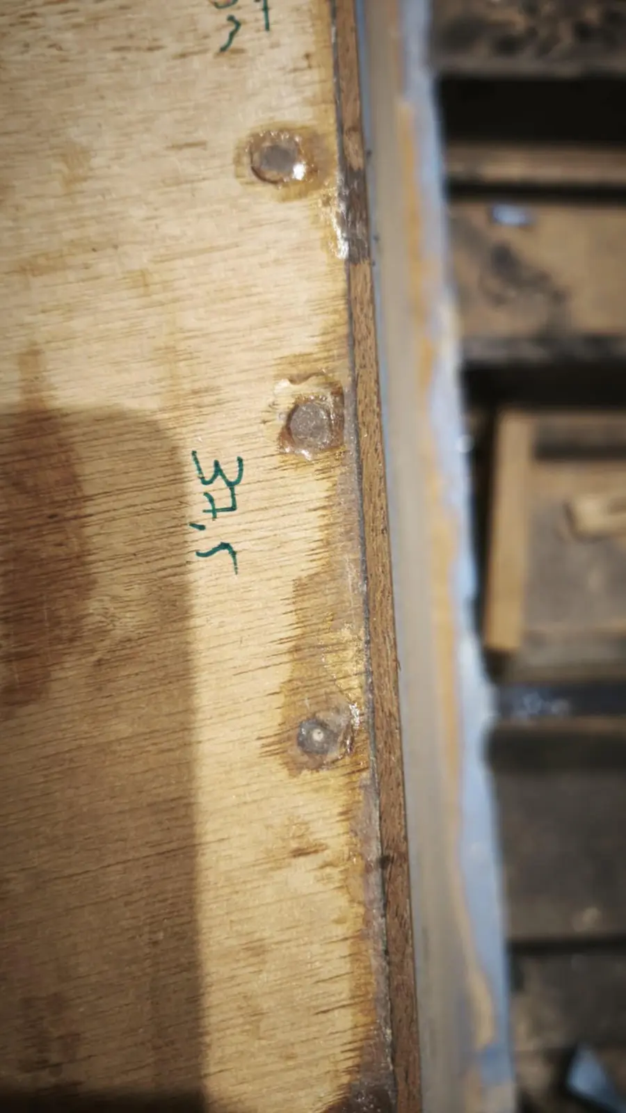
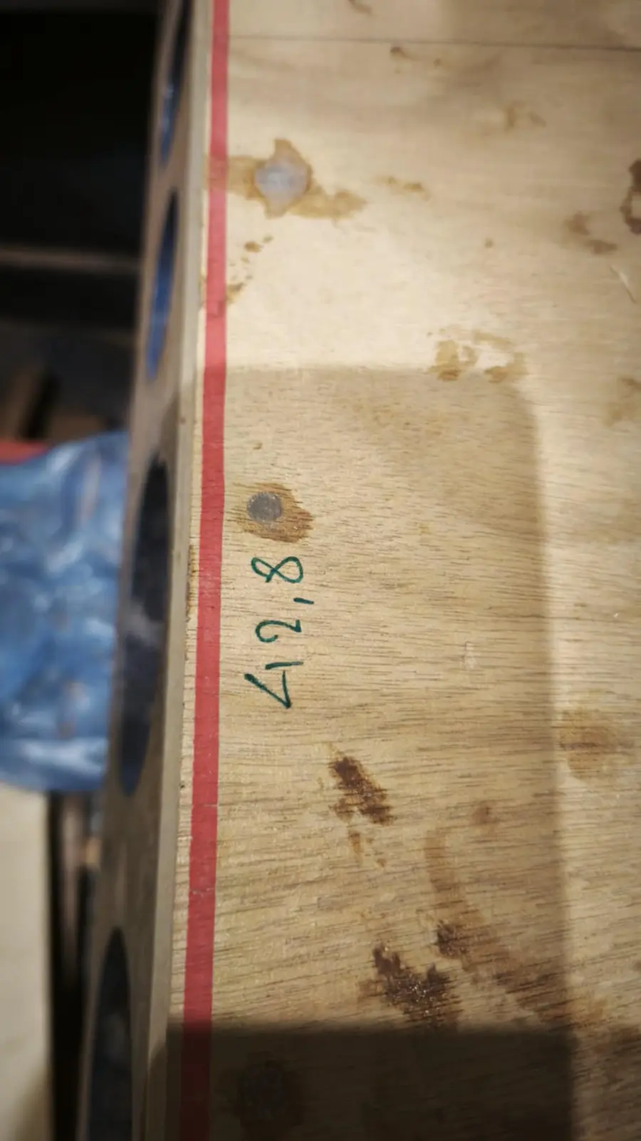
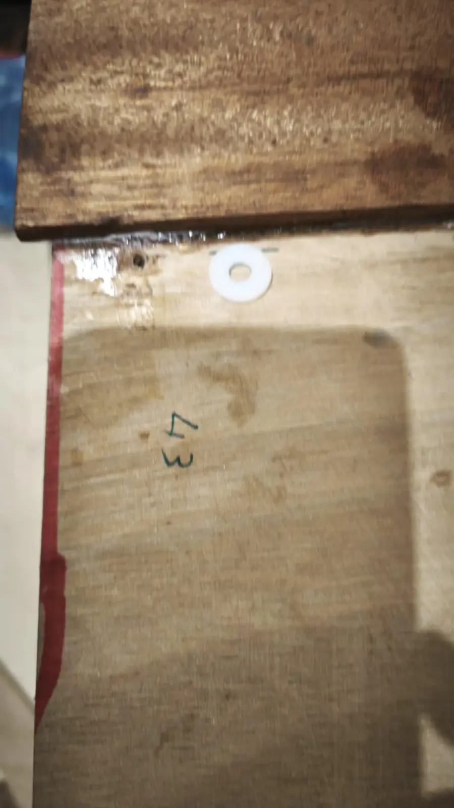
The drill bit itself was put into the holes that had been drilled, to hold the plywood in position, and then it was screwed down. To give the screws minimal contact with the epoxy I used plastic washers. After a few hours the screws have to be turned very slightly to break the bond, so they do not stick even with that small amount of contact with the resin.

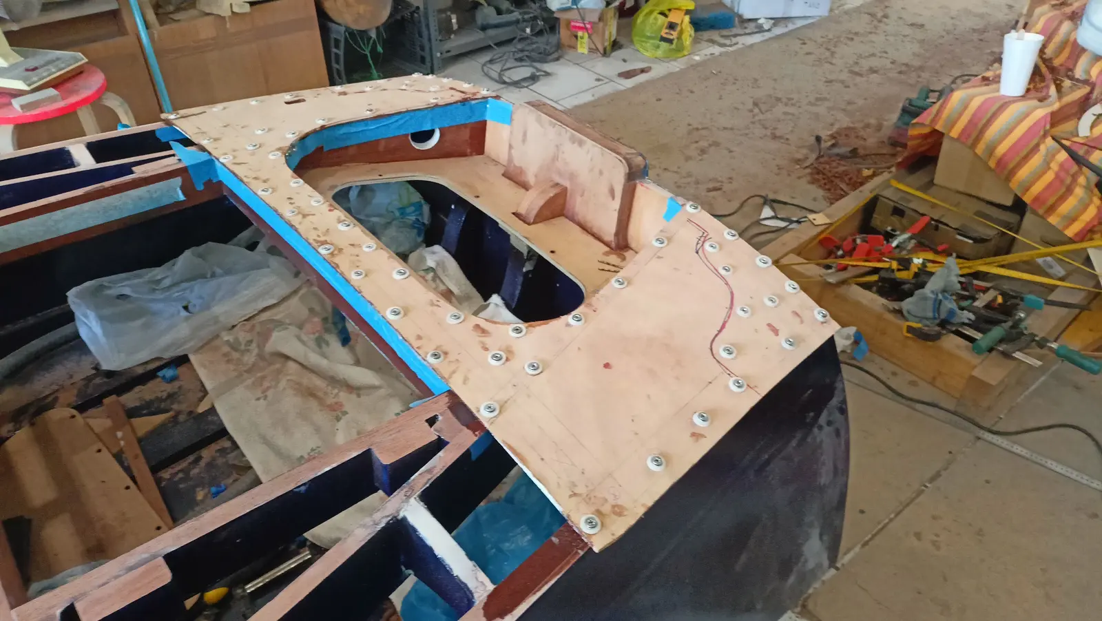
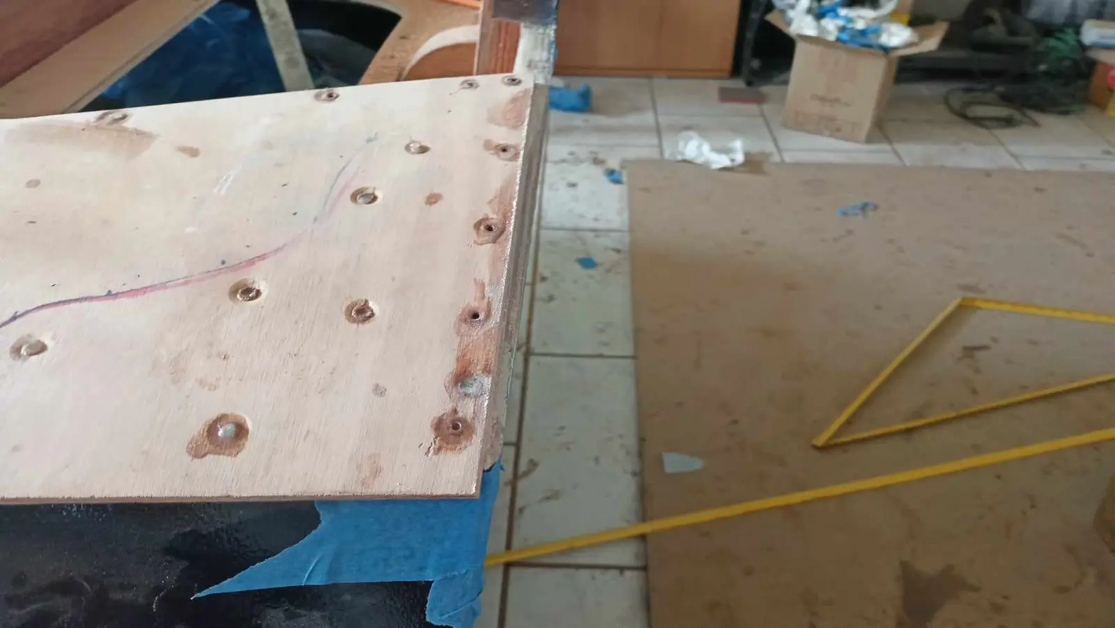
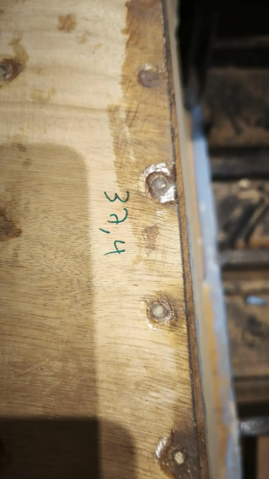
Once the plywood was fixed in the right position I opened out all the holes the screws would go into with a small drill. That was both so the screw goes in easily and, mainly, so I have the exact point it will go in.

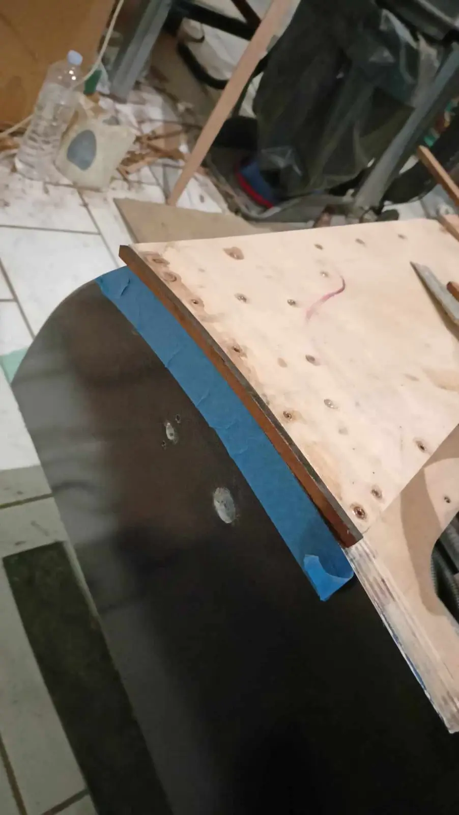
As can be seen in the last photograph, the plywood did not go right to the end of the boat. At the end, because the plywood would look bad, a sipo fillet will go on.

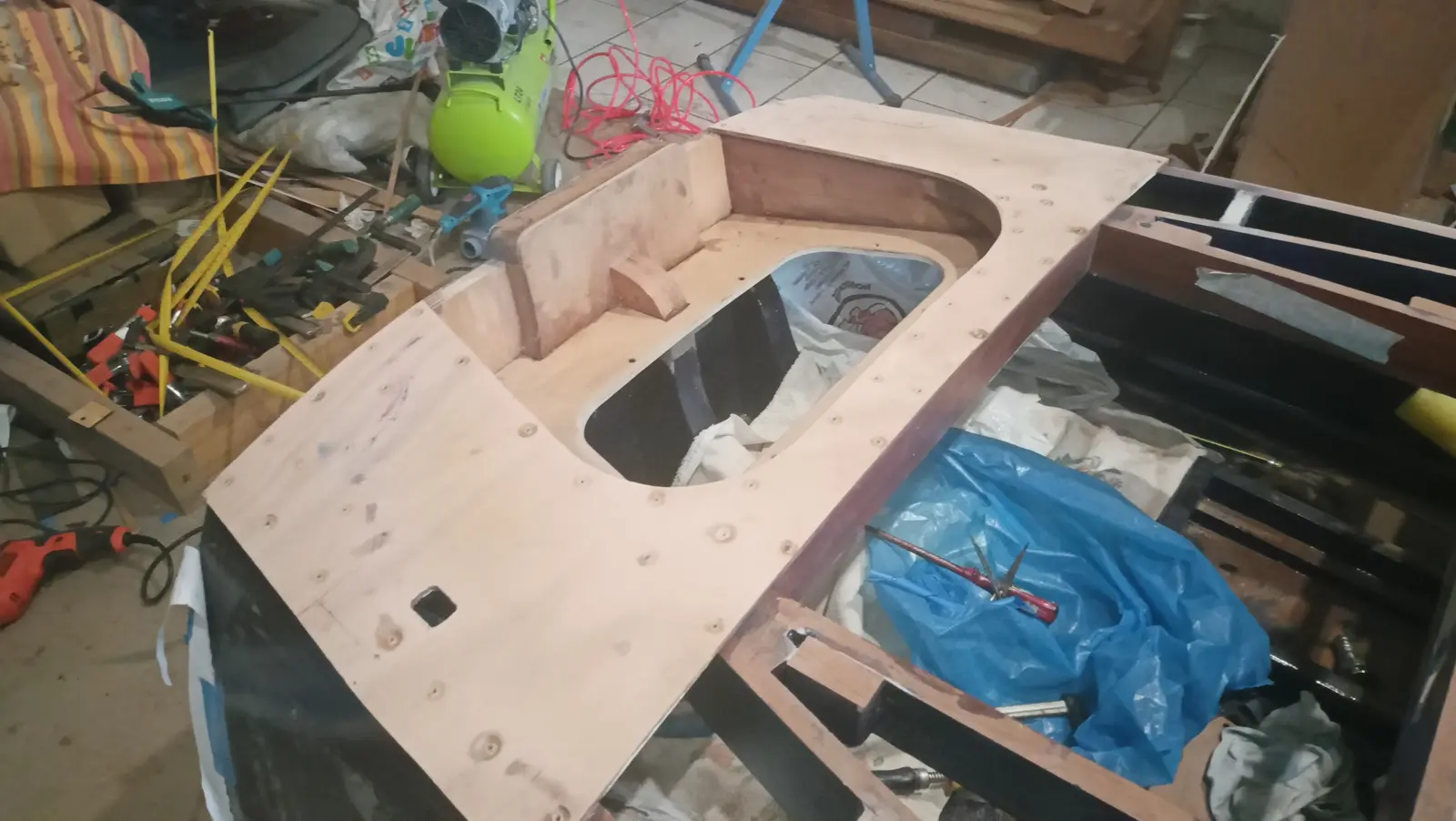
The same process for the middle piece, but with two pieces, one left and one right.

Because the seat is at the forward end of the central plywood, I decided to put a solid timber fillet here as well.

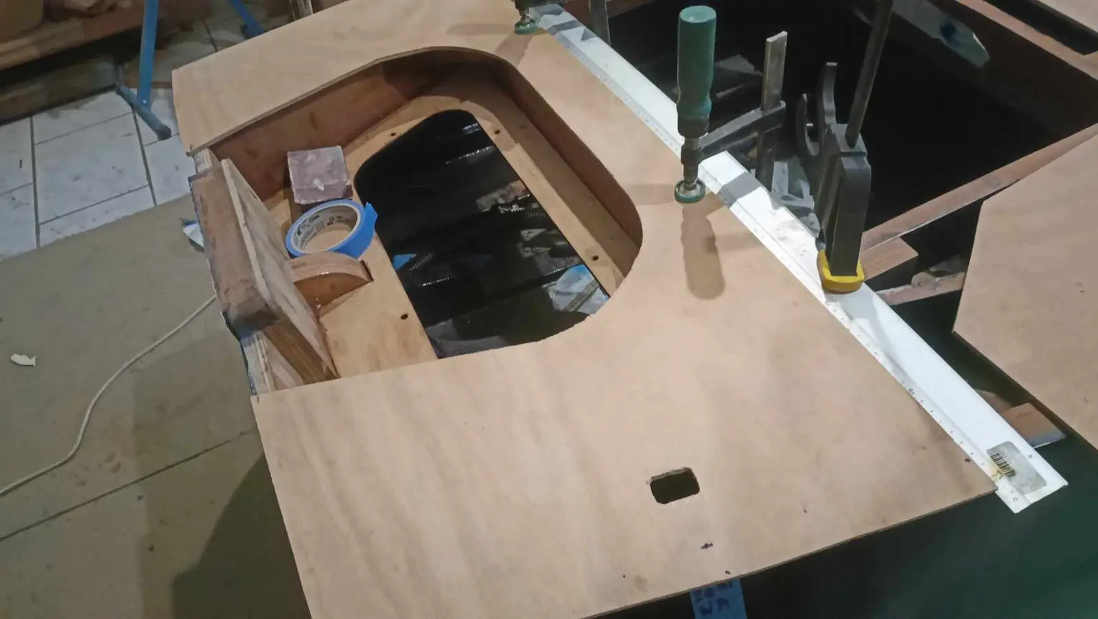
Before moving to the forward end I drilled a hole in the aft plywood for the control cable to come out of, and then completely shaped the inner edges of the middle pieces where the locker doors will go.

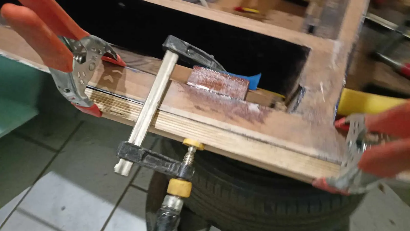
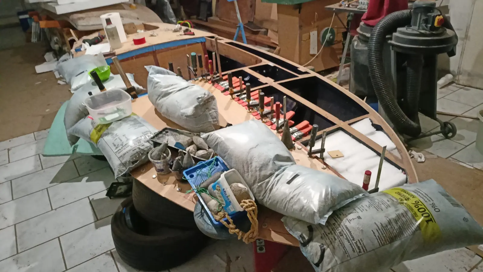
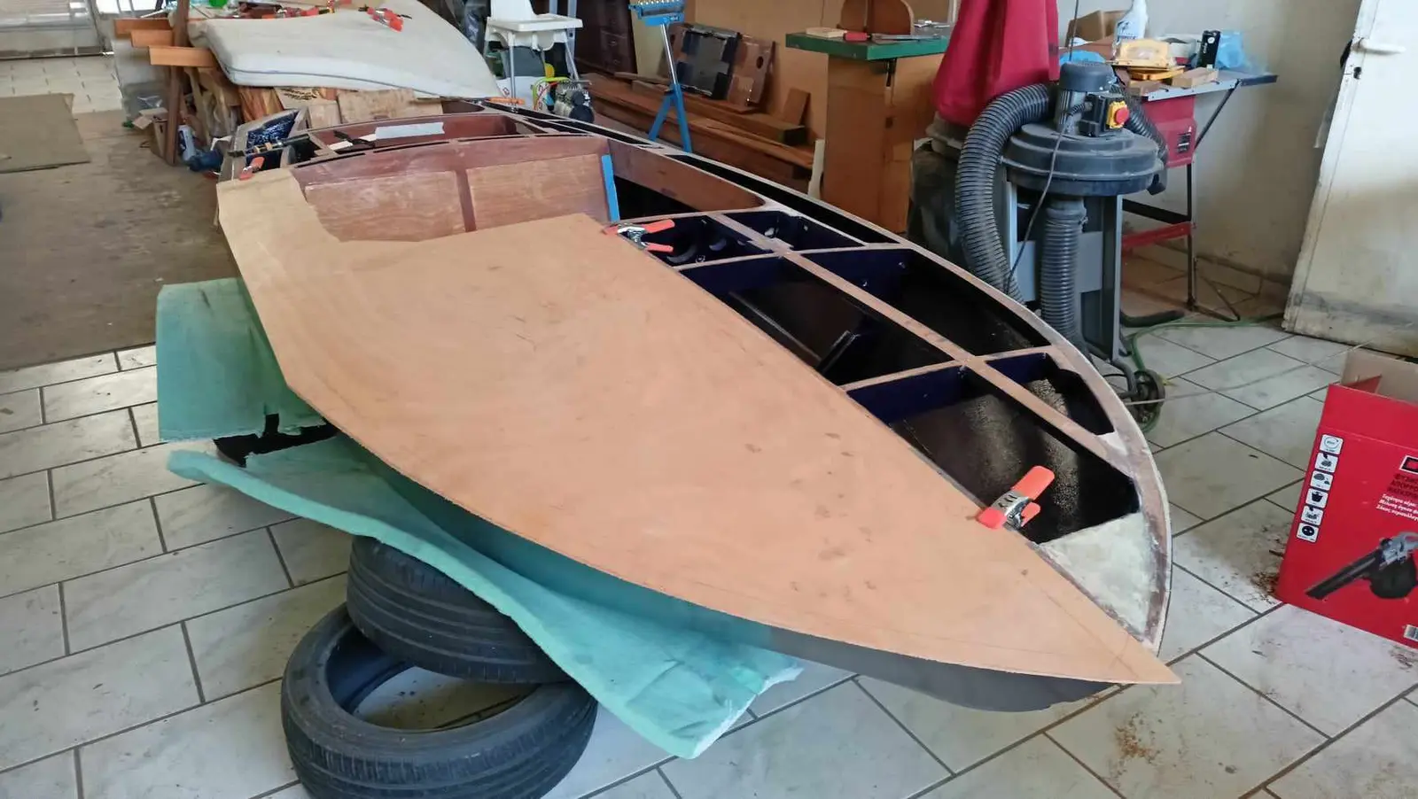
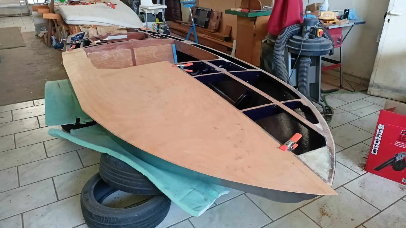
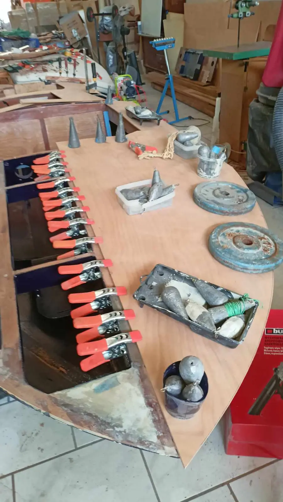
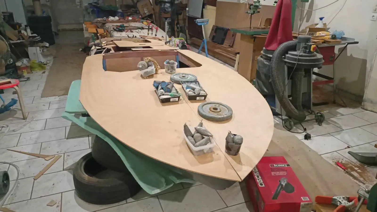
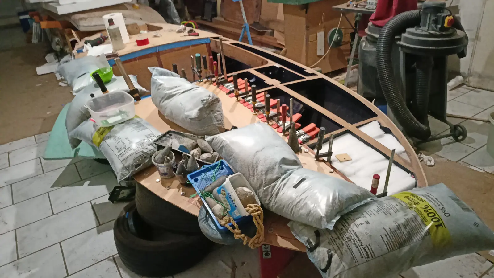
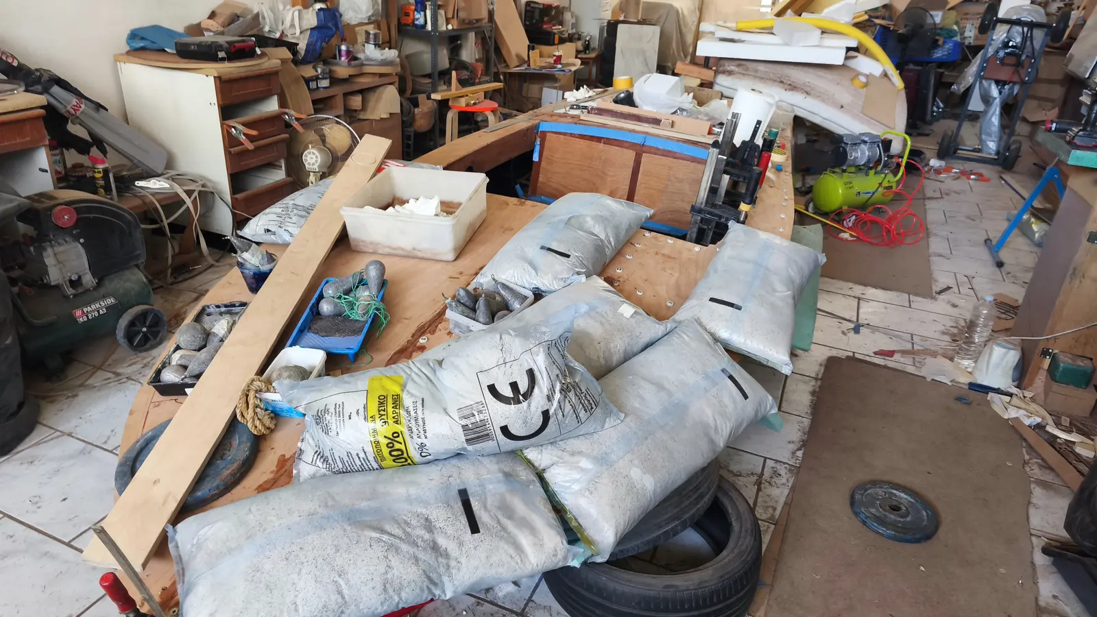
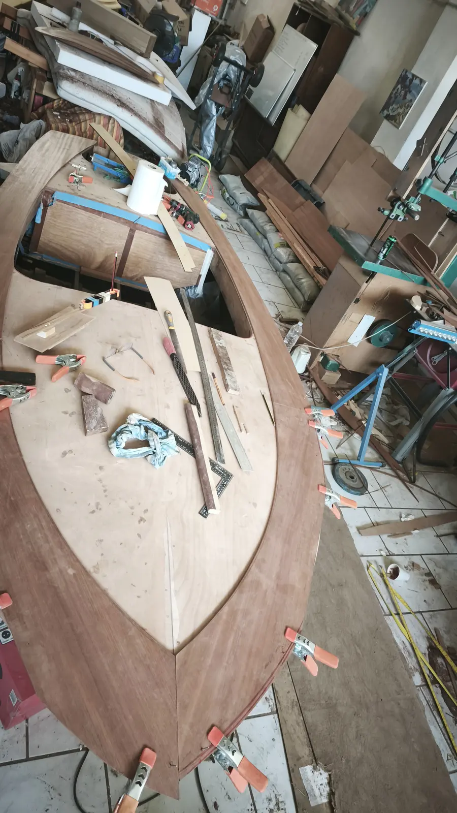
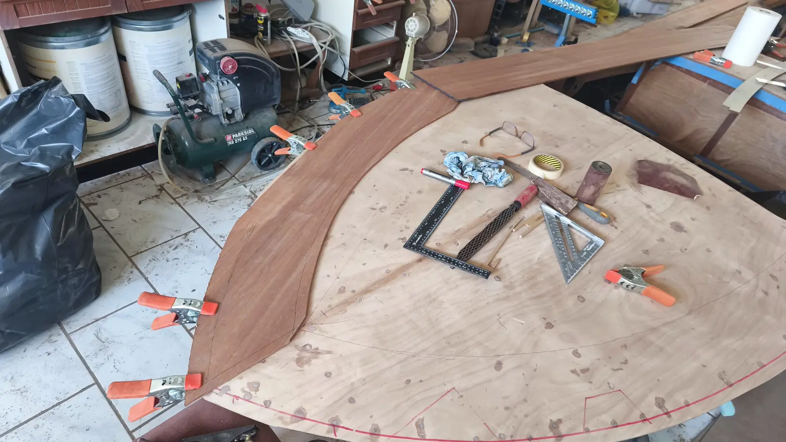
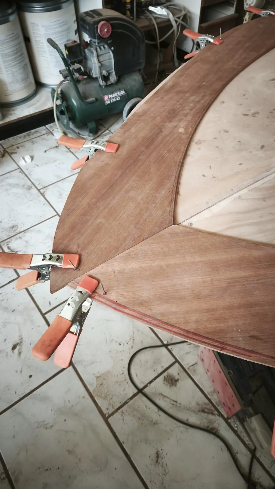
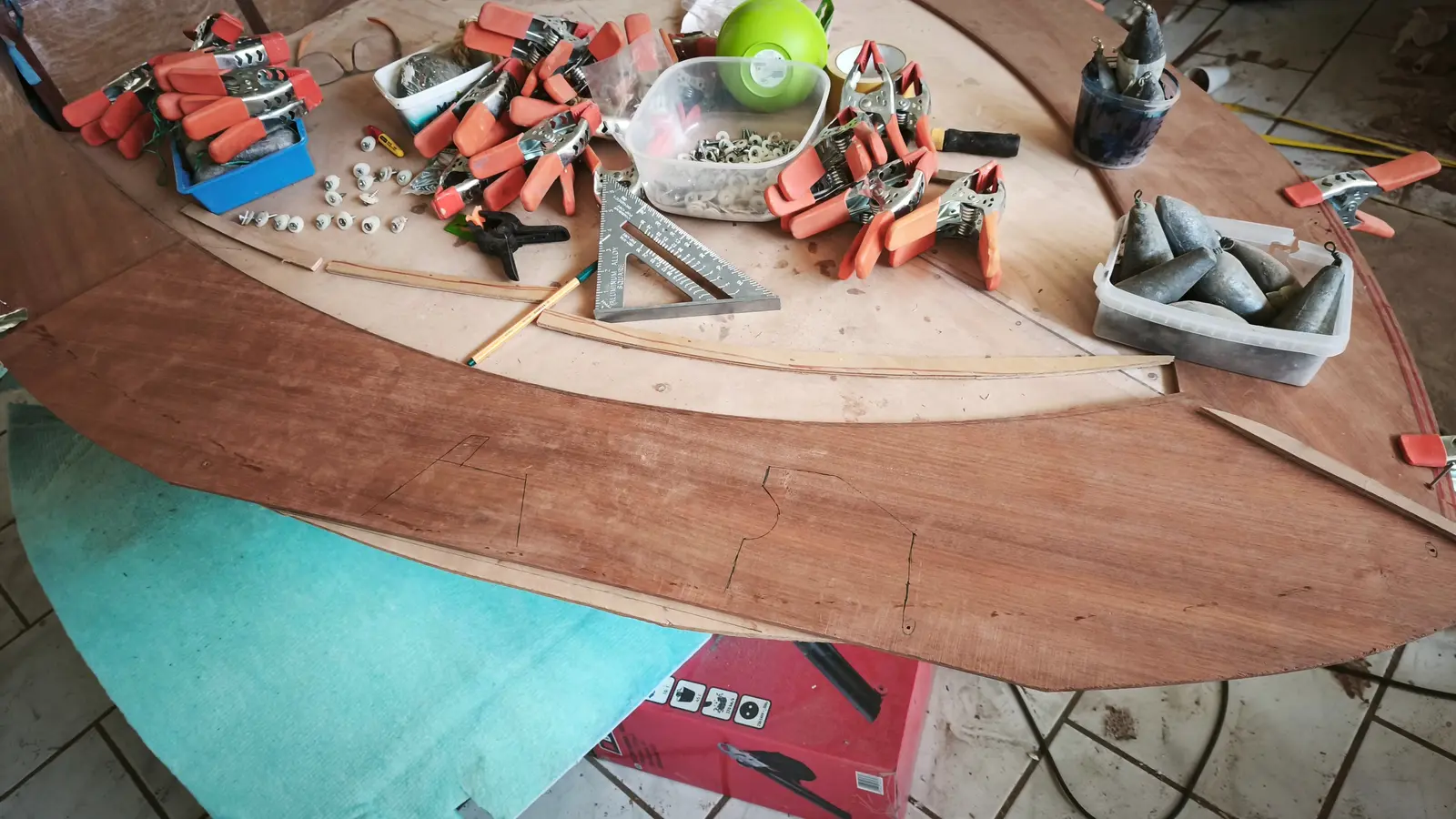
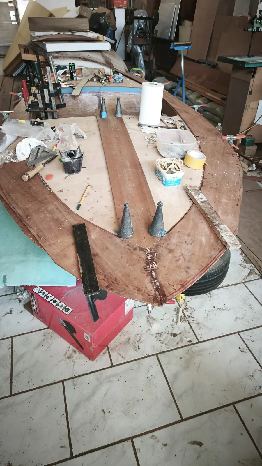
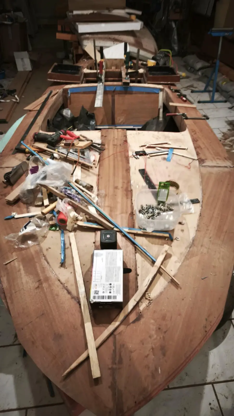
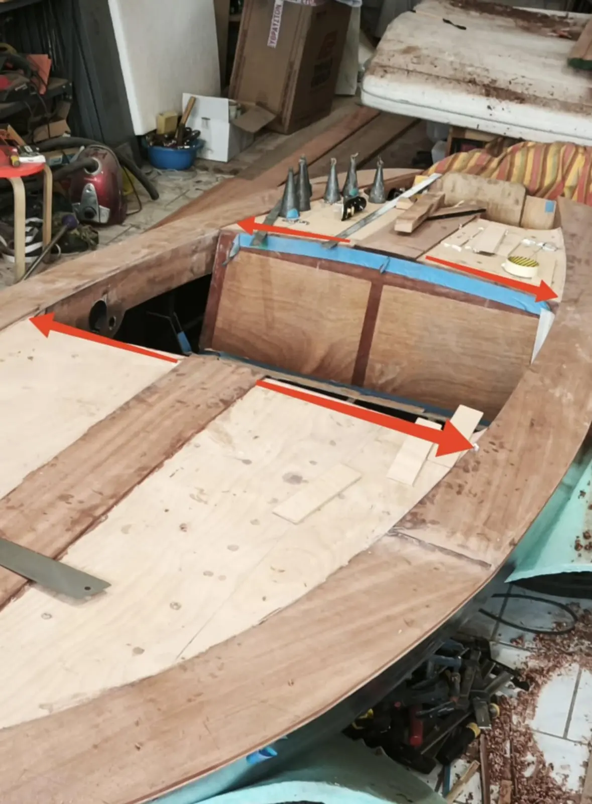
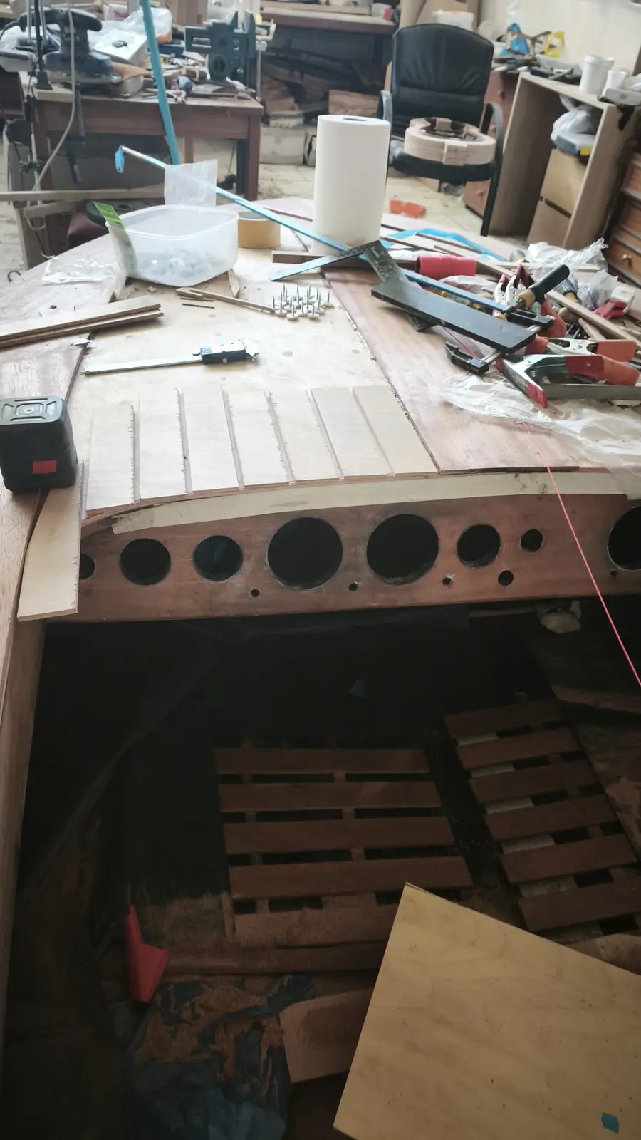
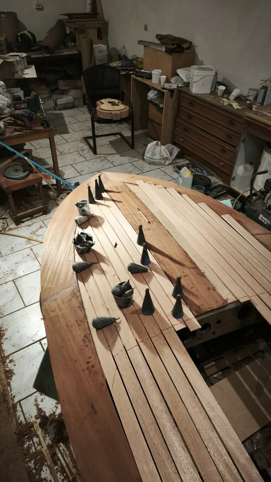
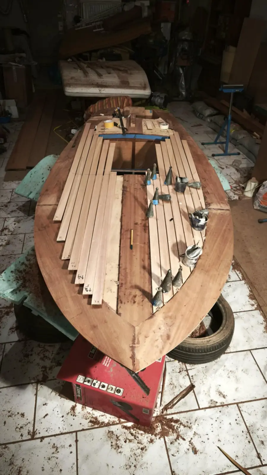
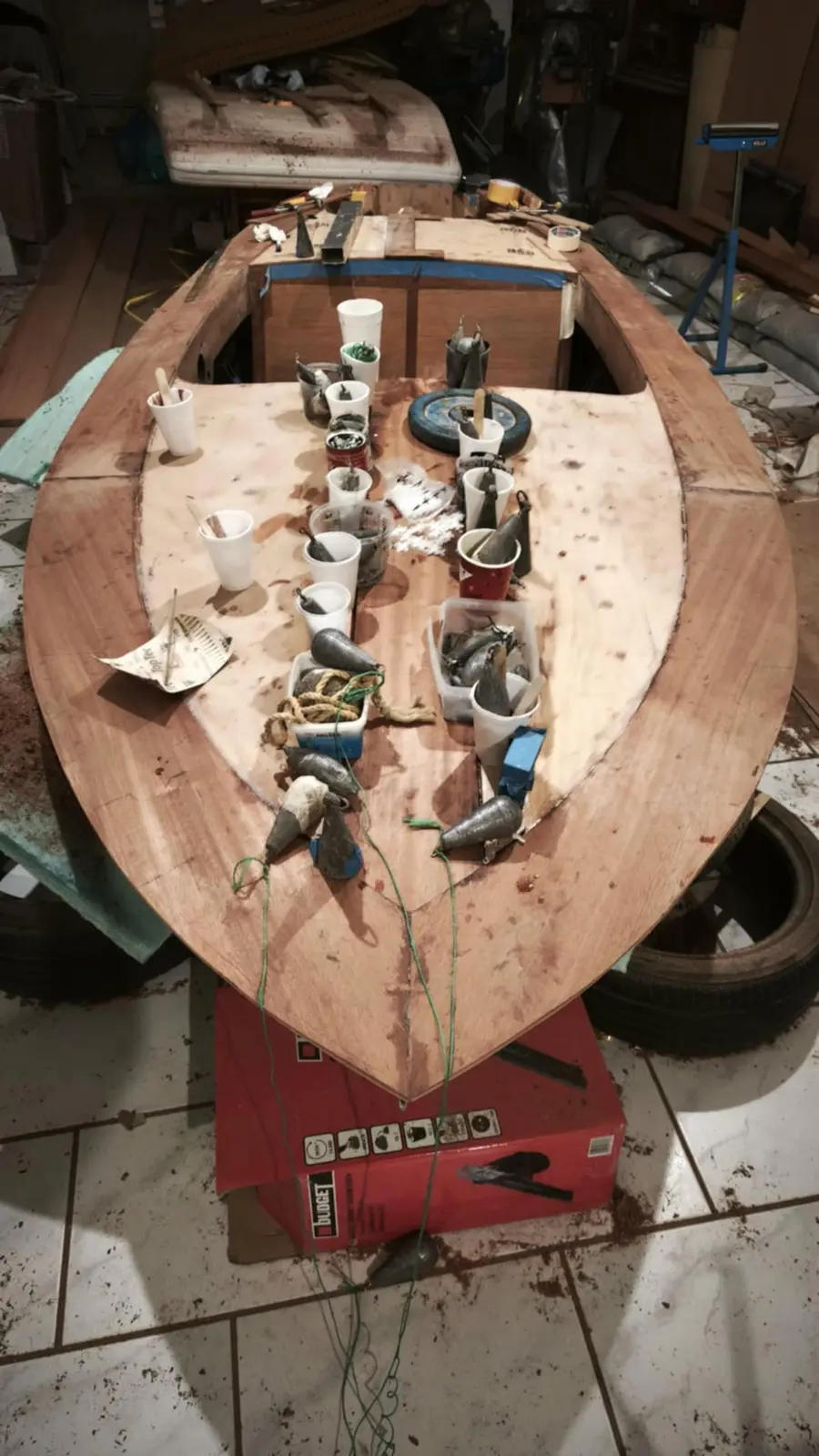
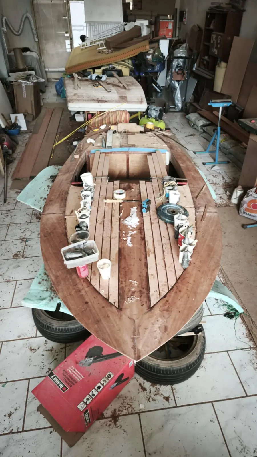
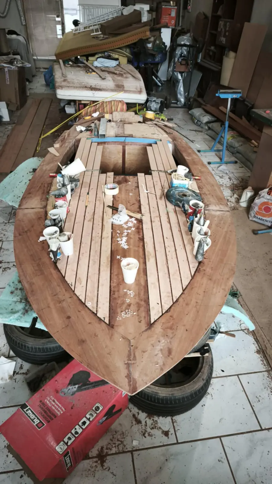
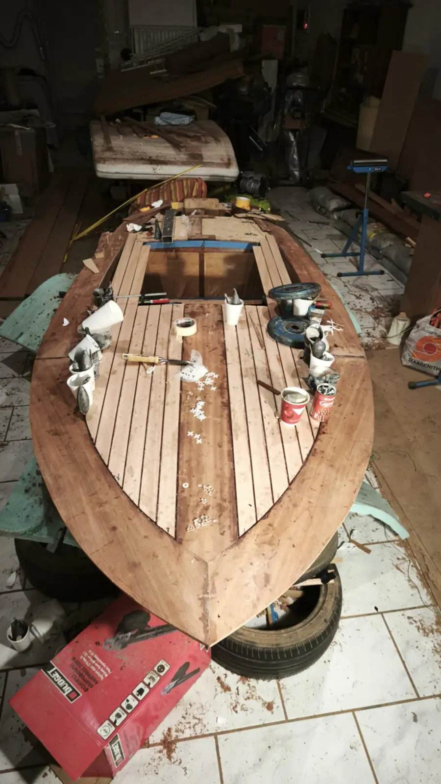
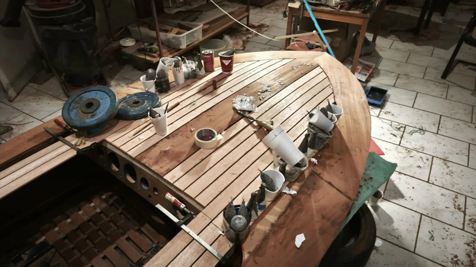
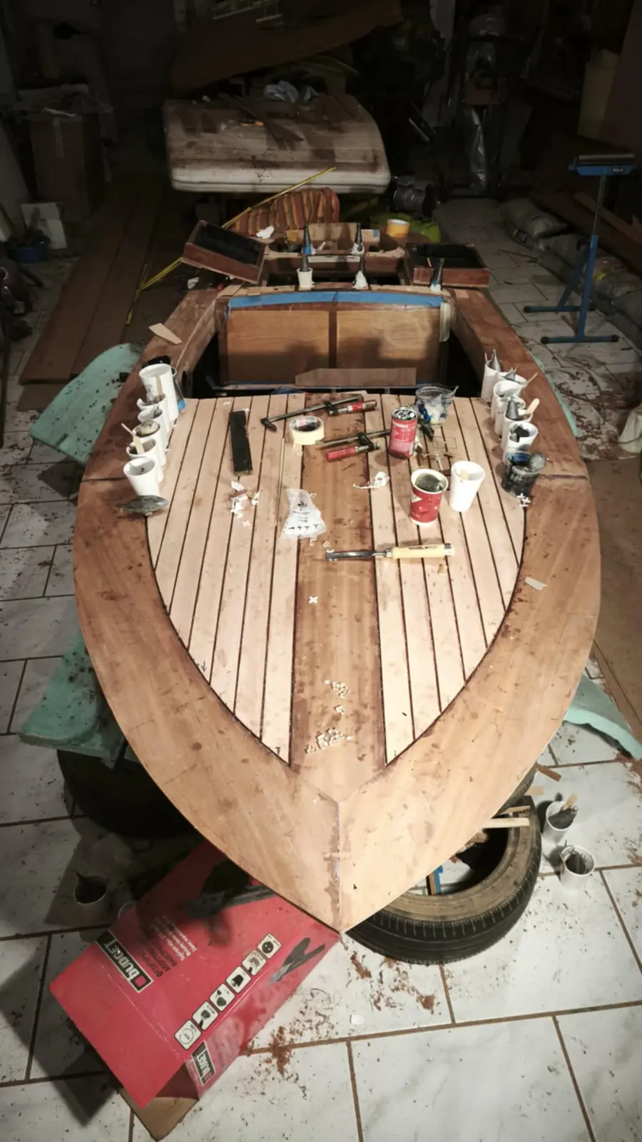
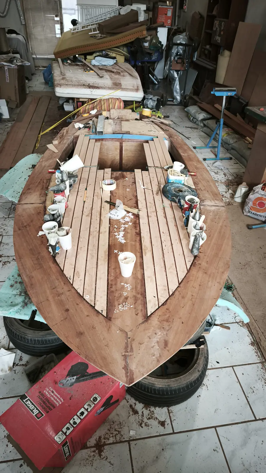
Next comes the forward piece. The main thing at the forward end is to cut them as perfectly as possible where they meet on the centreline. A rasp was used to get a completely straight edge on the first one. I did the same again. There is a peculiarity here in that the forward mooring cleat has to go in first and then the flotation material, so it does not make life difficult for me later given how little working space there is. At the forward end of the boat the plywood has quite a pronounced curve. I decided not to rely on screws alone but to use plenty of weight to help the wood bed down onto the framework timbers. I will do that with a lot of fishing weights, dumbbells and bags of sand.

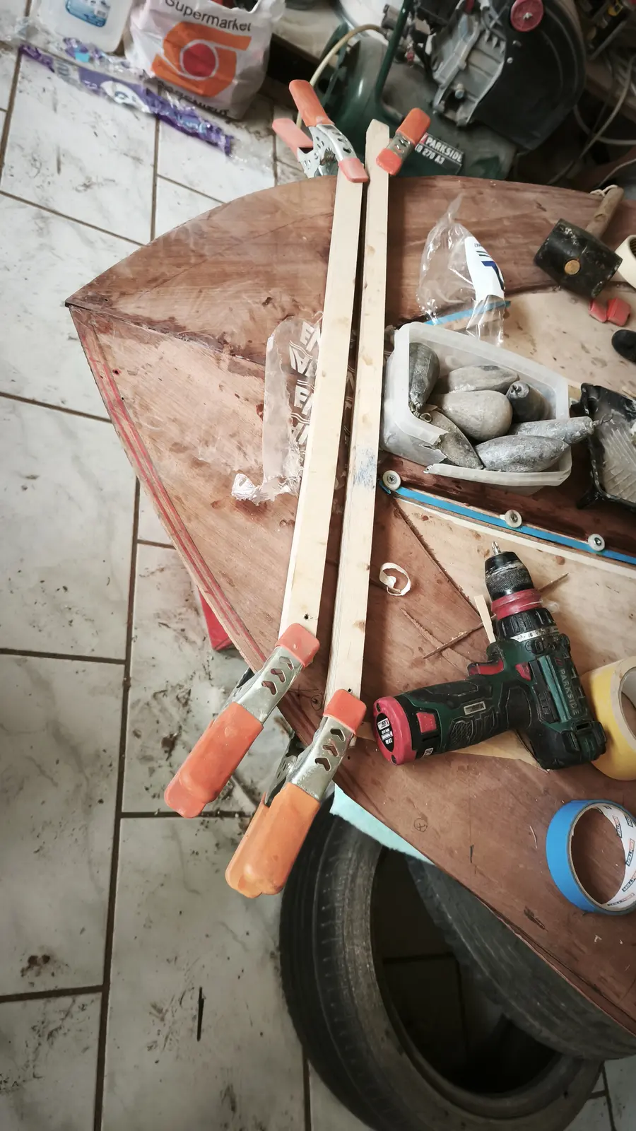
The second piece of plywood forward was glued as well. It was glued using the same process but more screws went in, as clamps could not be got onto the joint. I decided to leave some screws in at the points where there was a lot of pressure, so we do not have any accidents. Not, of course, the plywood coming away from the rest of the boat, since epoxy is very strong. What I was afraid of was the plies of the plywood delaminating from each other. Unlikely, I imagine, but what does 5 screws weigh? Silicon bronze, needless to say.

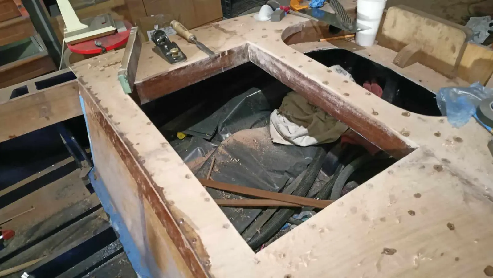
I filled the holes from the other screws with resin. That resin may also do the job of the screws, since it grips both glued parts. Then I sanded the plywood smooth and took a little off in the centre, because they came to a slight point there, to get it fair.

Next it is the locker's turn, so the first layer of the "deck" can be completed.

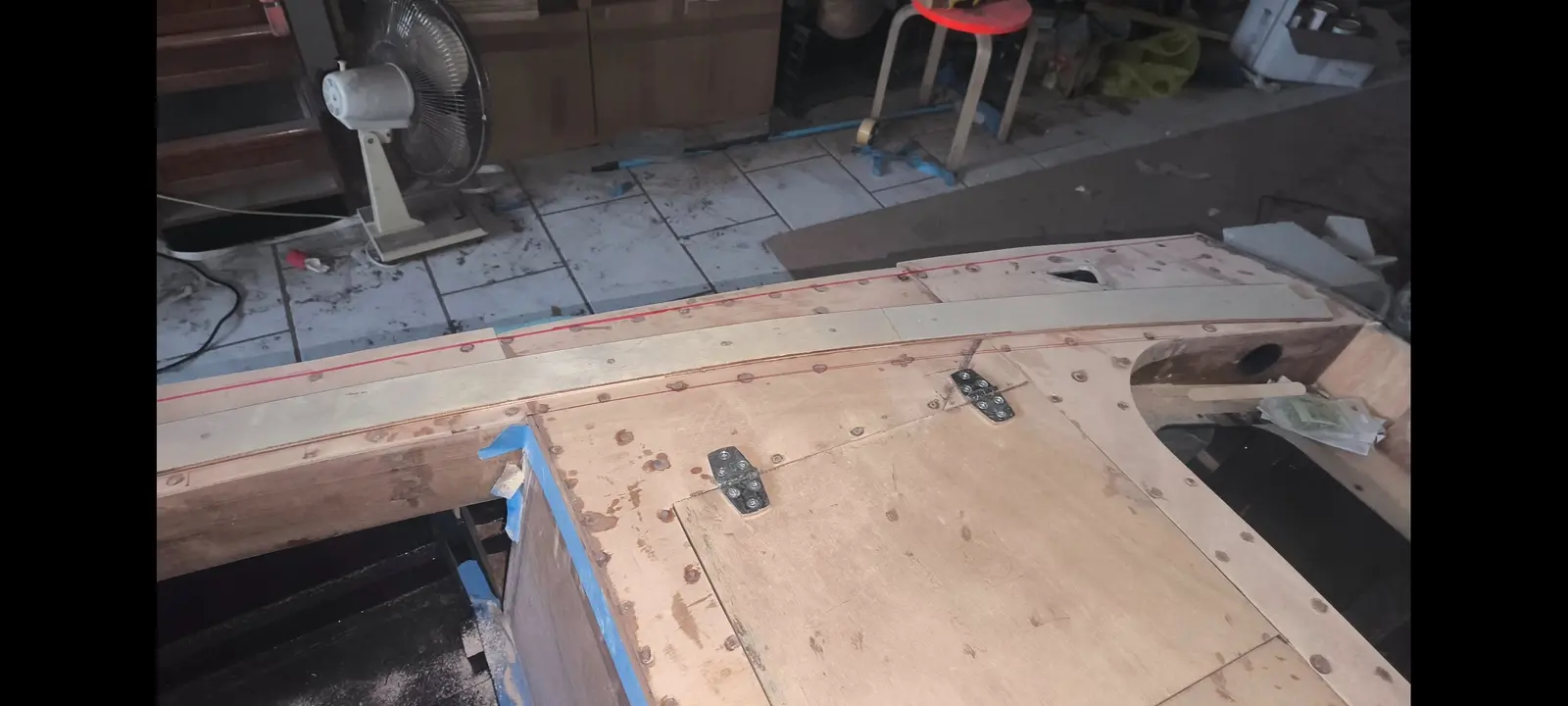
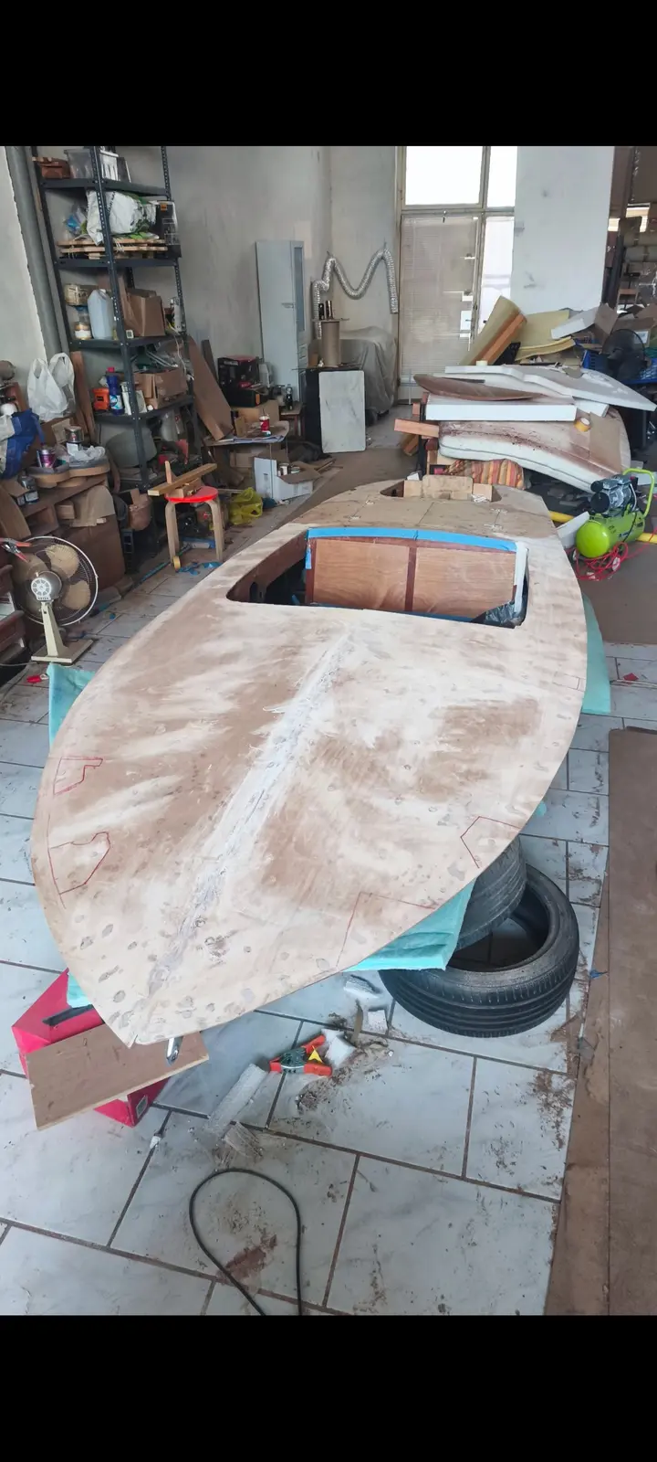
Once that was done I took off the excess plywood at a few points and sanded to get rid of the glue. Finally I transferred onto the plywood the positions of the reinforced areas underneath it where the various fittings (cleats and so on) will be installed.

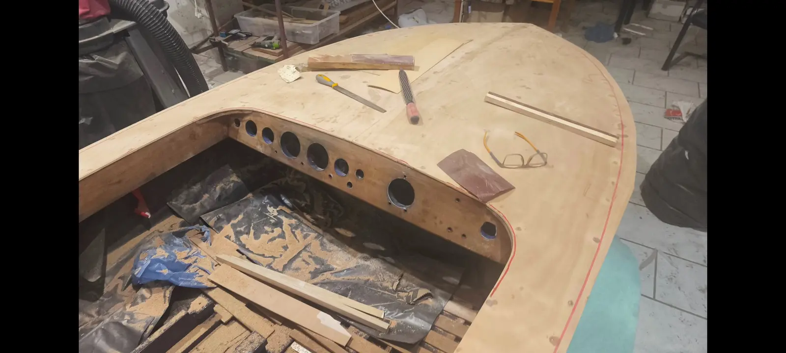
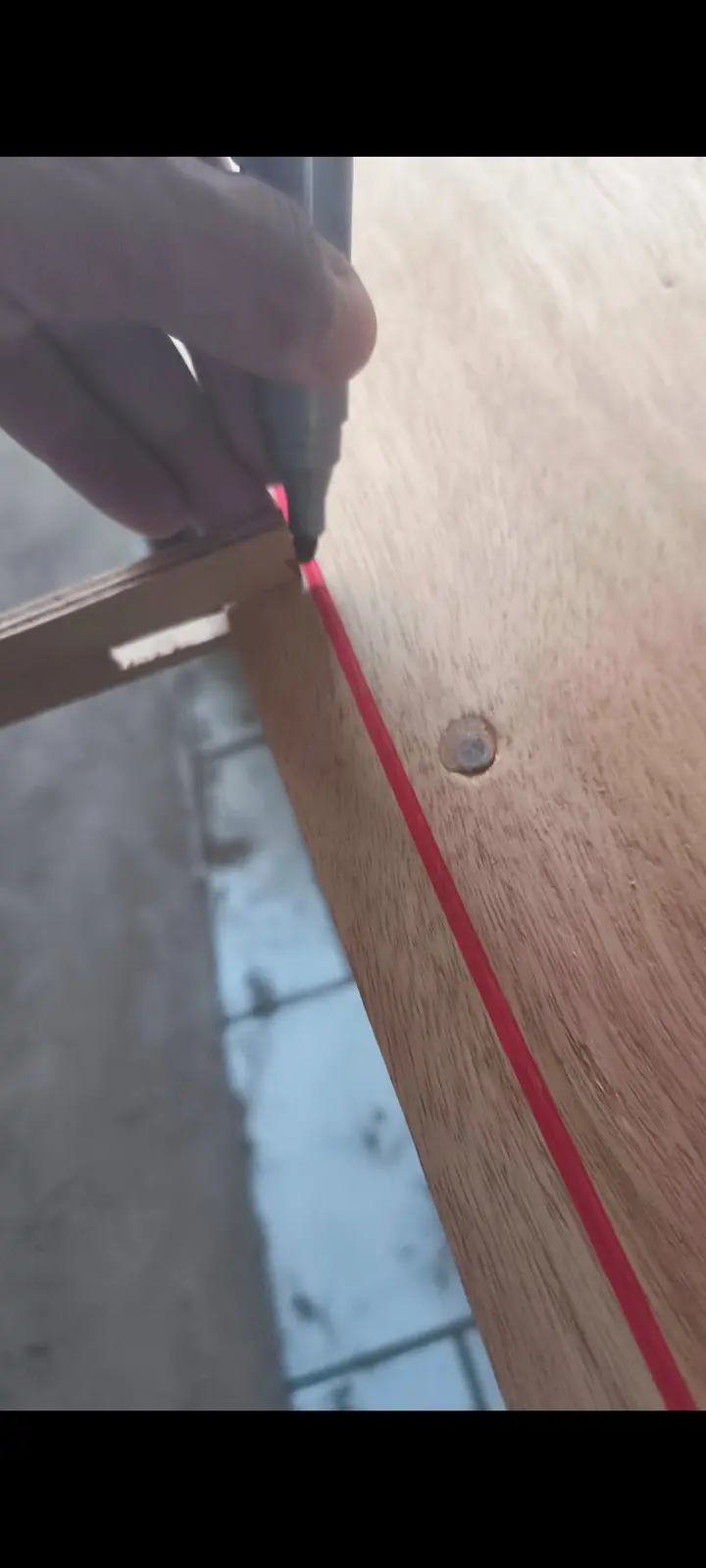
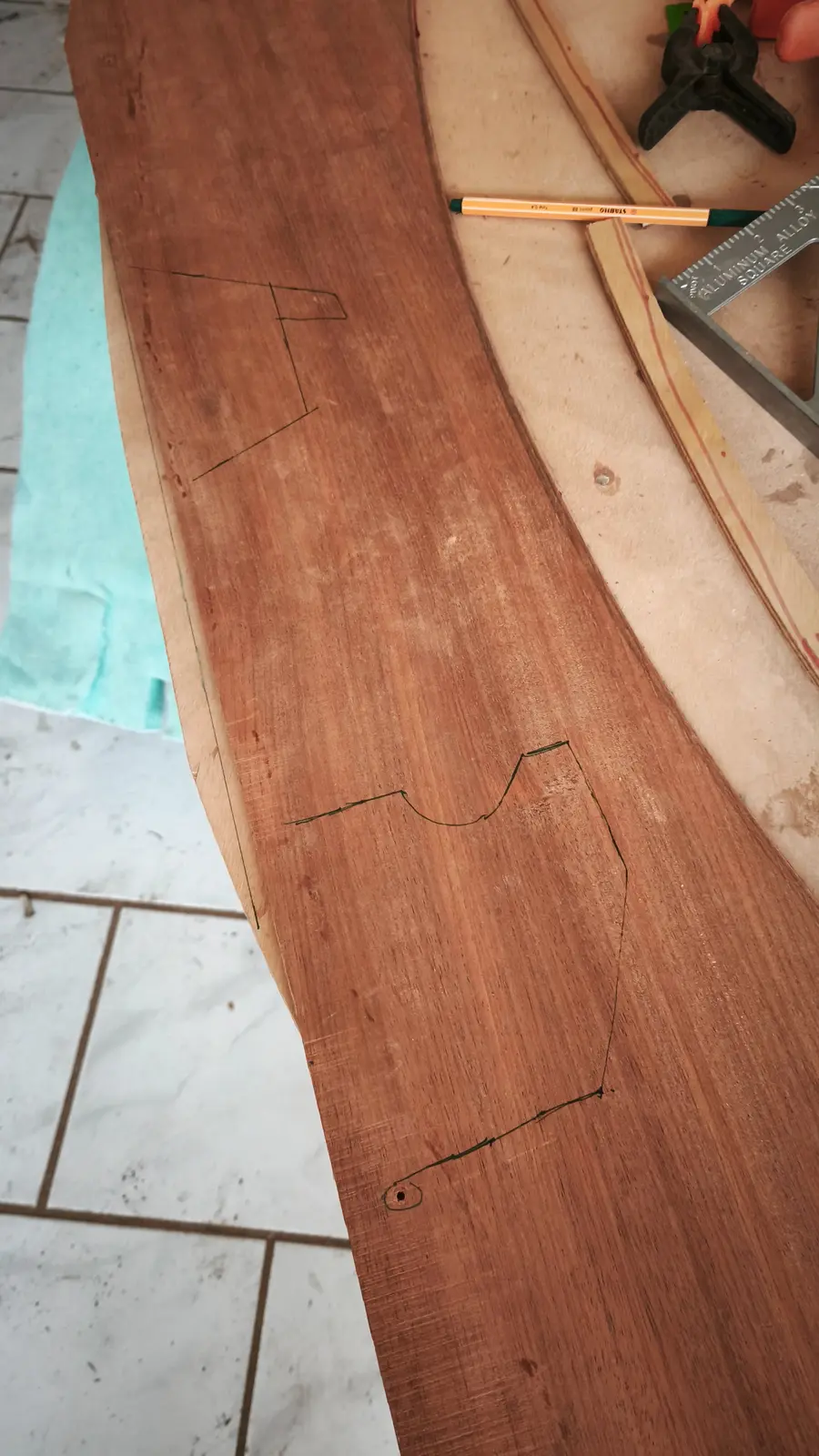
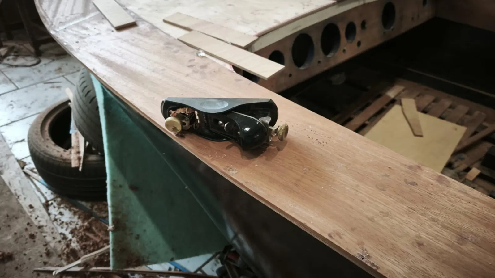
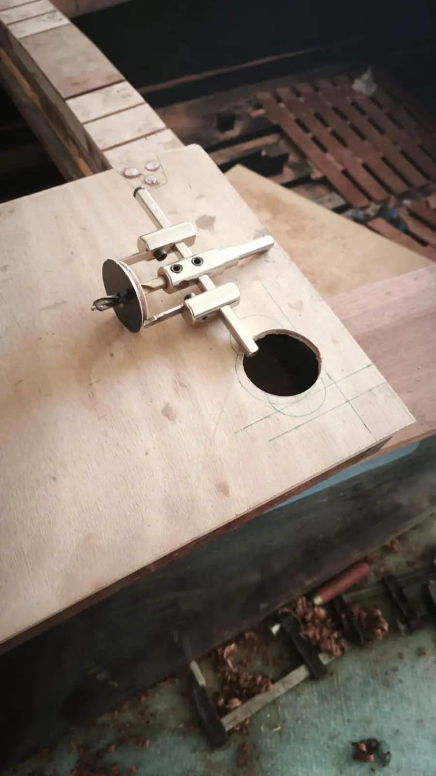
With the tool I made I marked the outline of the boat all the way round, with completely the wrong marker pen because the tip was too thick. It will be marked properly when the tool for the inside edge of the perimeter timber is made. At the aft end I used the curve the deck has at its end.

At the same time the inner floor was prepared, so we are not standing on the hull.

Link

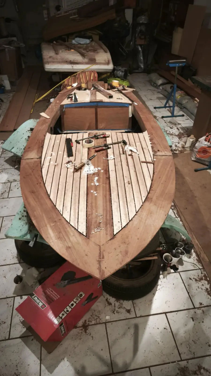
Laying the final mahogany deck

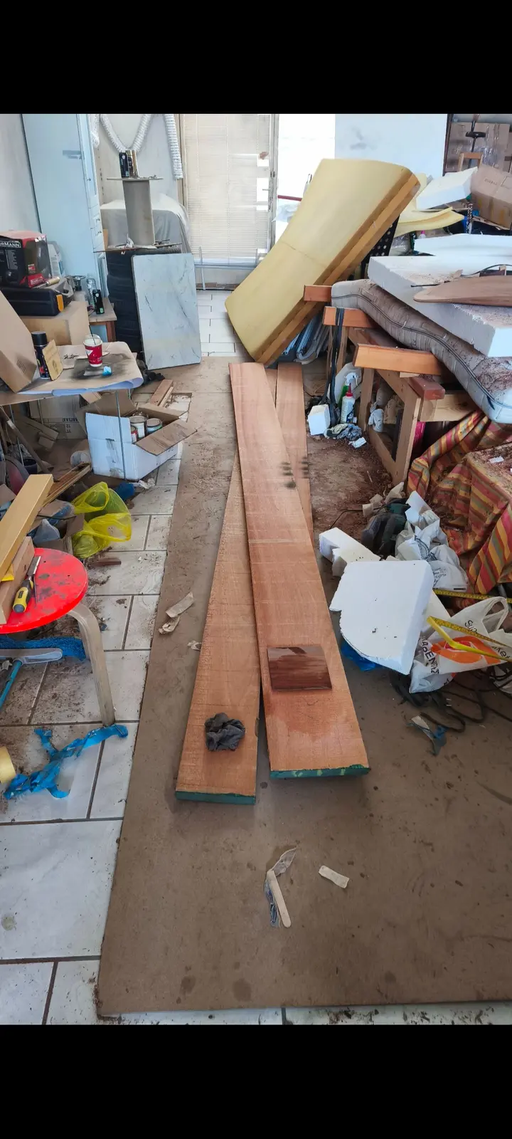
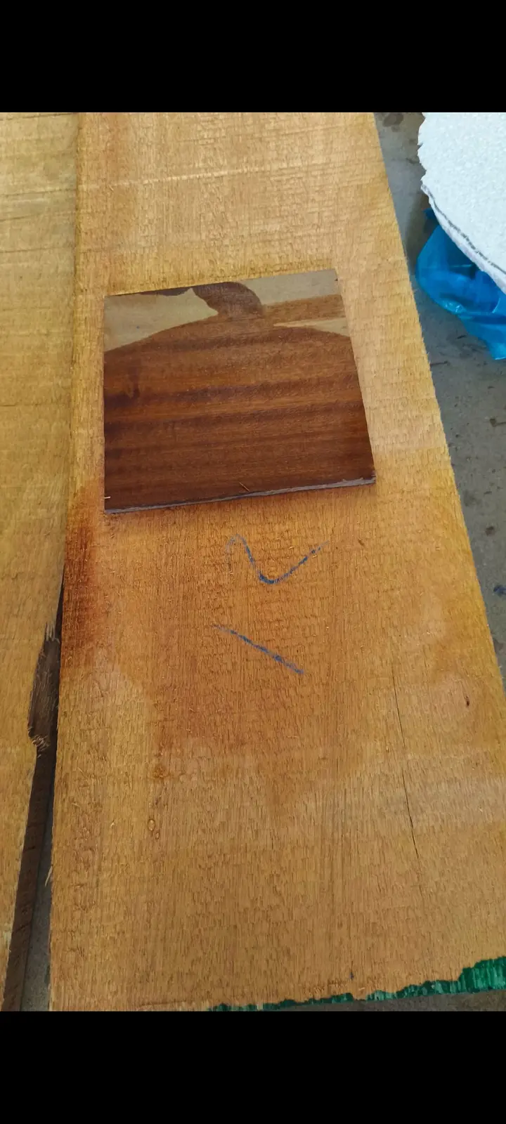
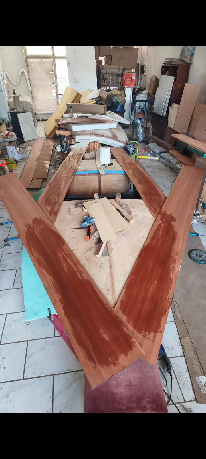
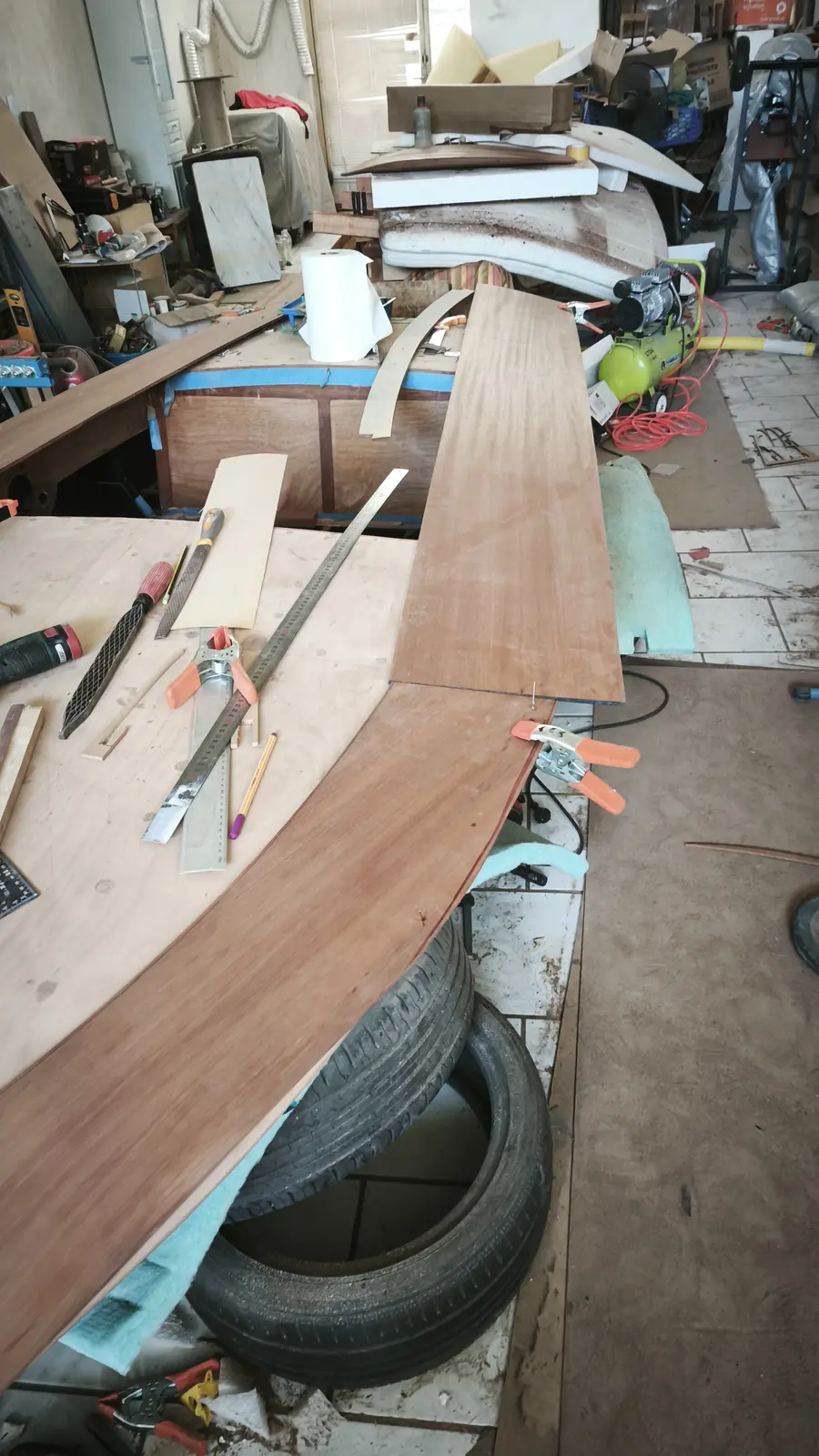
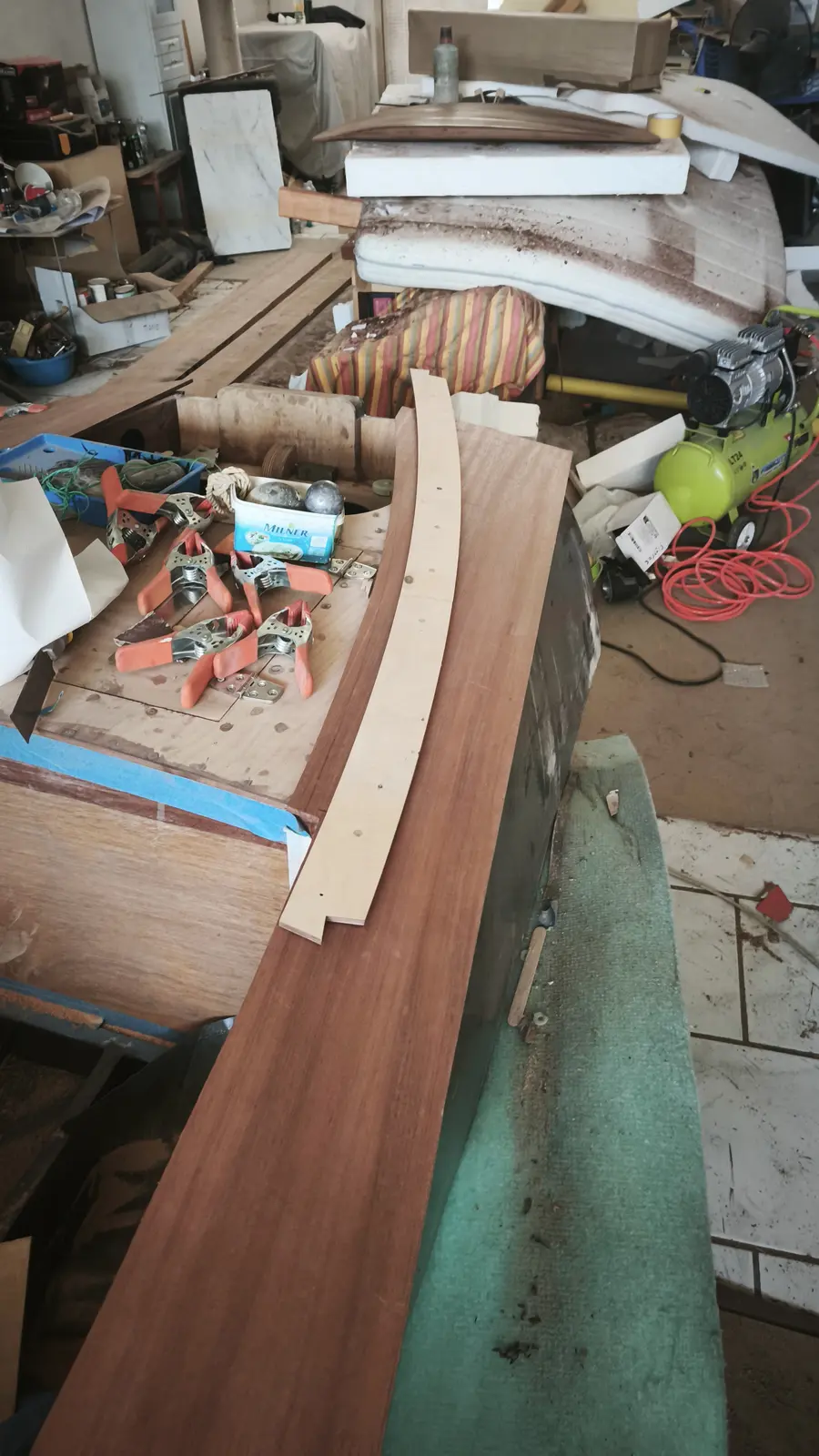
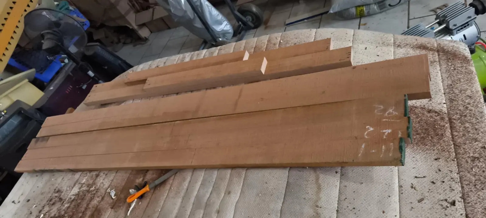
I bought the timber for the inner part of the deck. I found a very light coloured natural mahogany. The outer part of the deck will be made from a single sipo board 30 cm wide, so that a lot of pieces do not have to be glued up (see the photographs below). Because of the width I could not cut it on my own bandsaw, so it went to a boatyard to be cut.

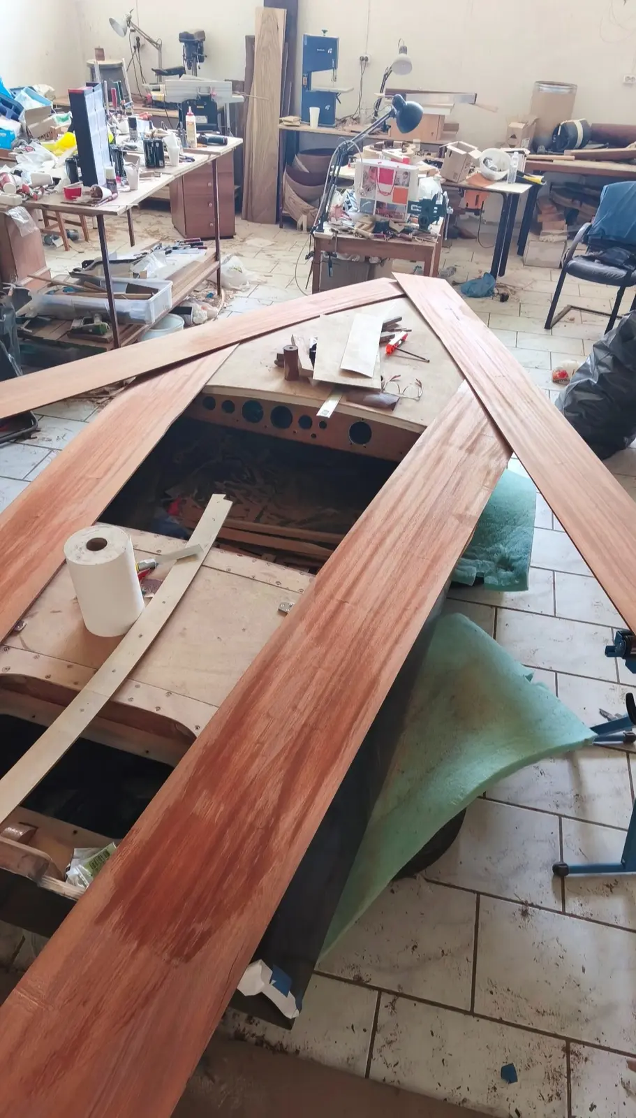
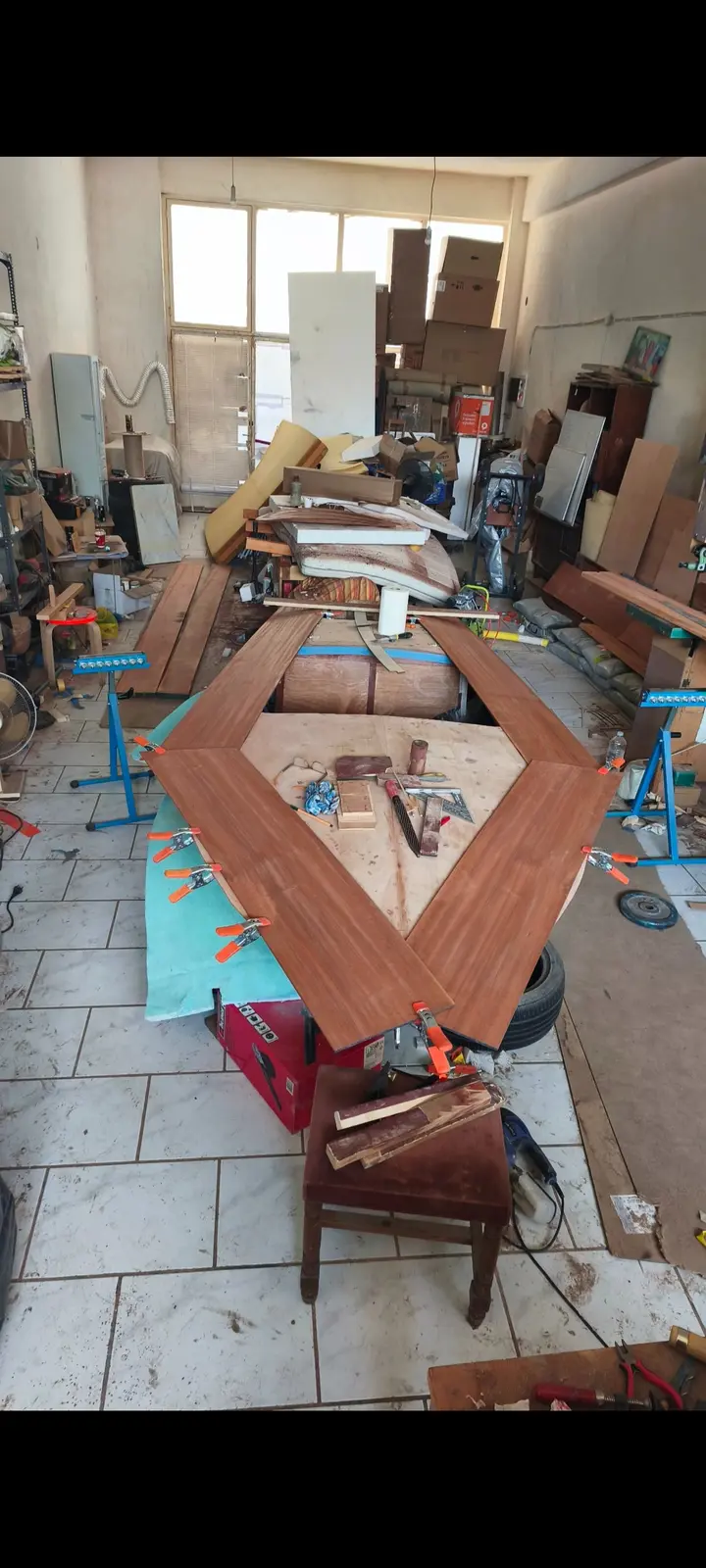
They were cut to the right shape (as far as the inner curve goes) with a great many measurements. I must have offered it up in position more than 20 times, as I have no more timber if I ruin it...

To get it in the right place each time, I put drill bits into 3 or 4 points, which hold it where it should be against the plywood underneath. The work is 95% complete, let us say, with the final cuts to be made when the forward pieces are glued.

Before gluing it I drew onto the timber the positions of the reinforcements underneath, for the stainless fittings to go into.

The first piece was glued.

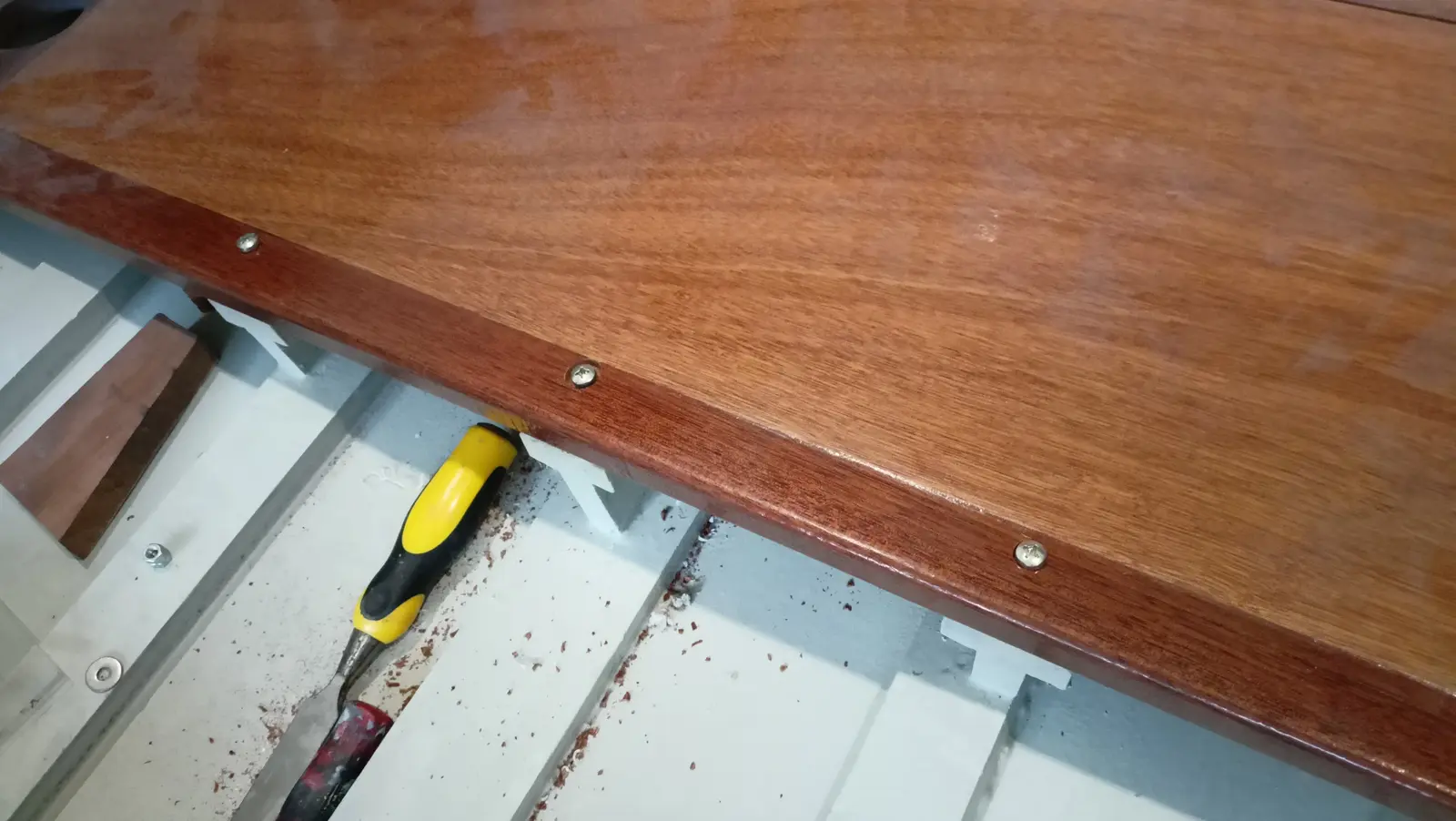
To press the timber down onto the plywood on the outside I used my clothes pegs. On the inside, screws with a washer that presses the timber down.

Then the rest of the large perimeter and central pieces were glued.

The hole was drilled for the control cable.

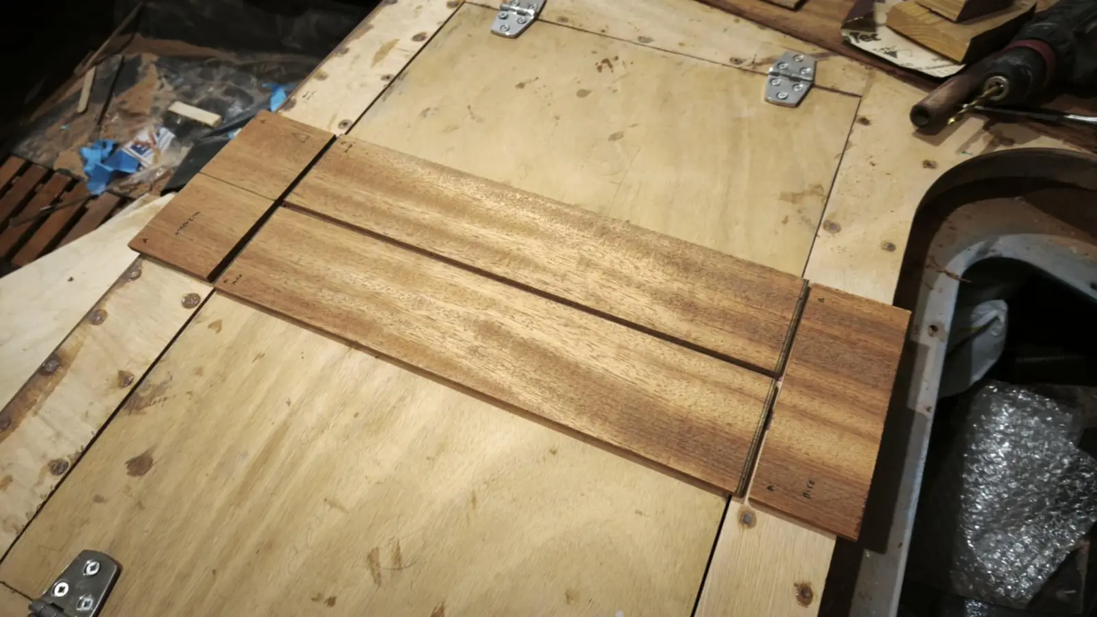
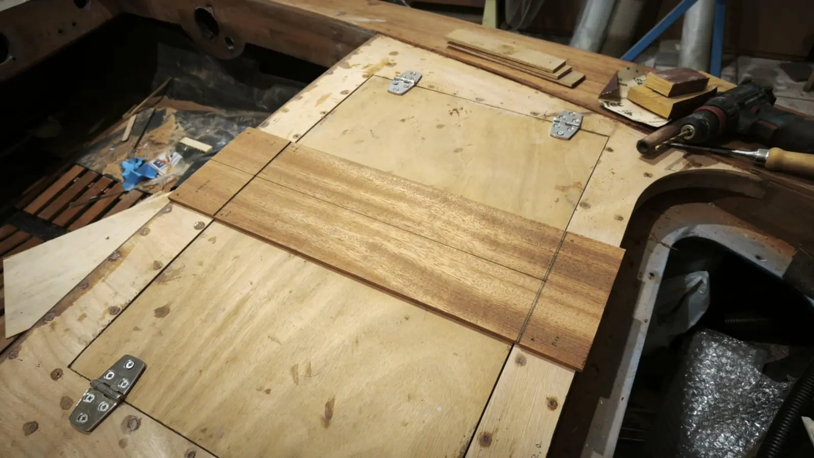
Then the central pieces were glued in the locker area. As well as the locker, timber had to be glued forward and aft of it. See the arrangement in the photographs below.

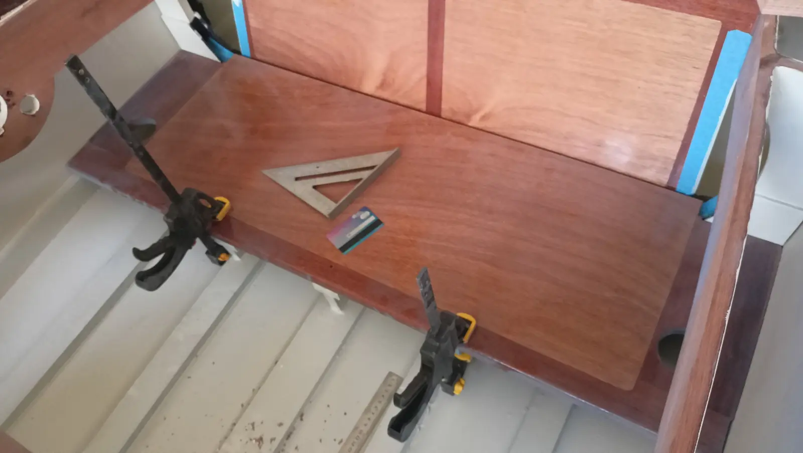
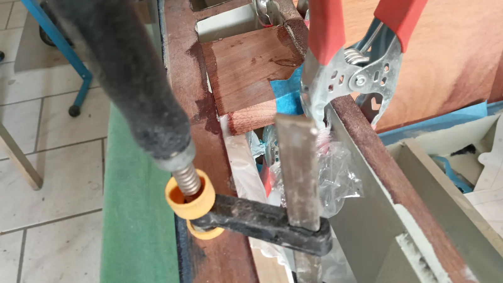
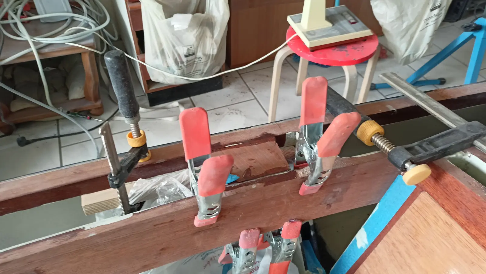
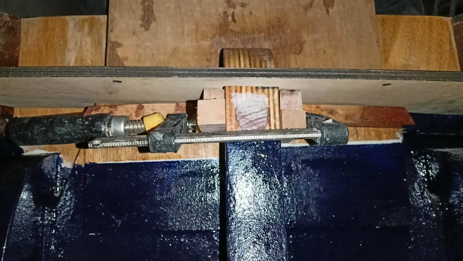
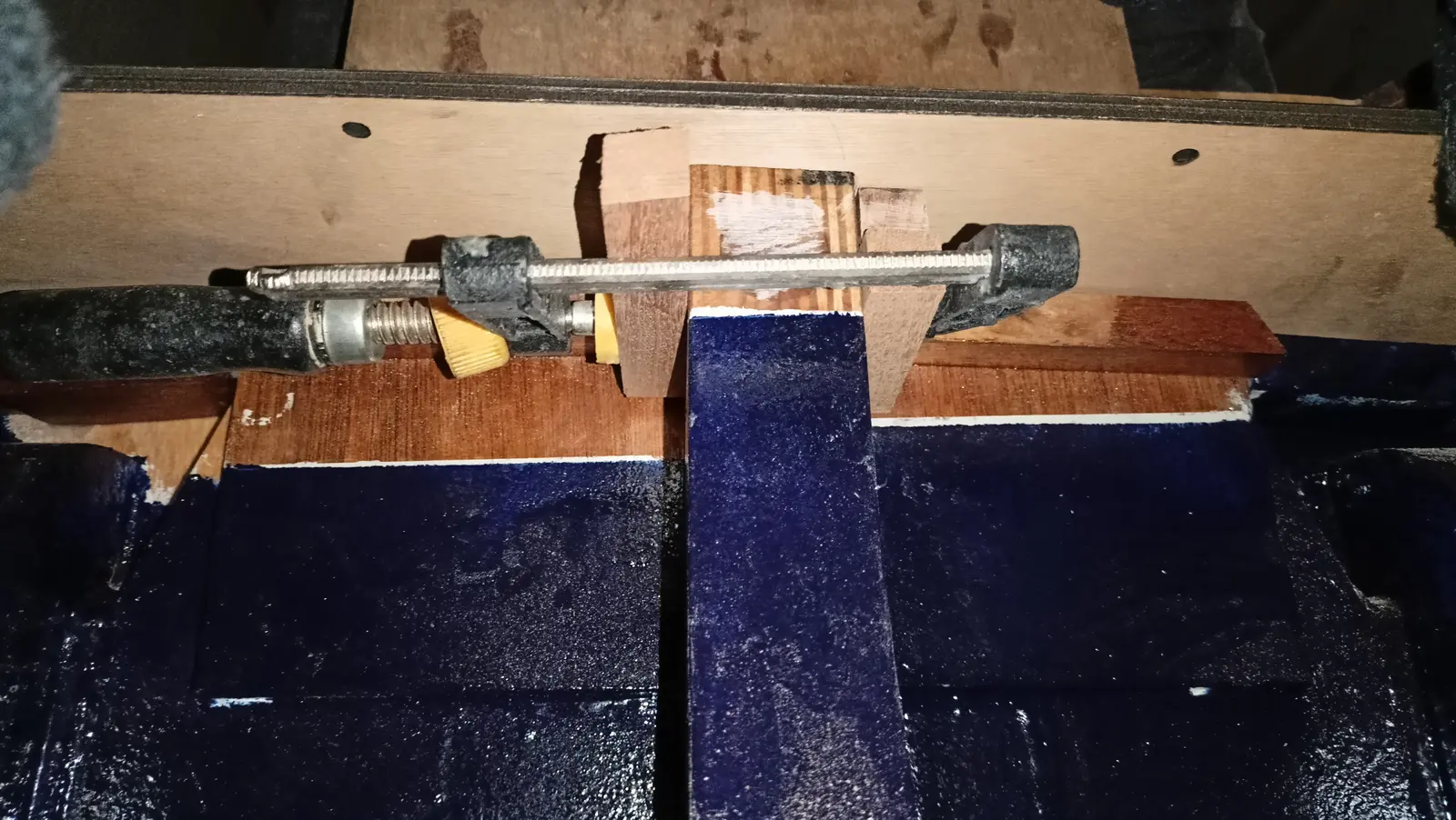
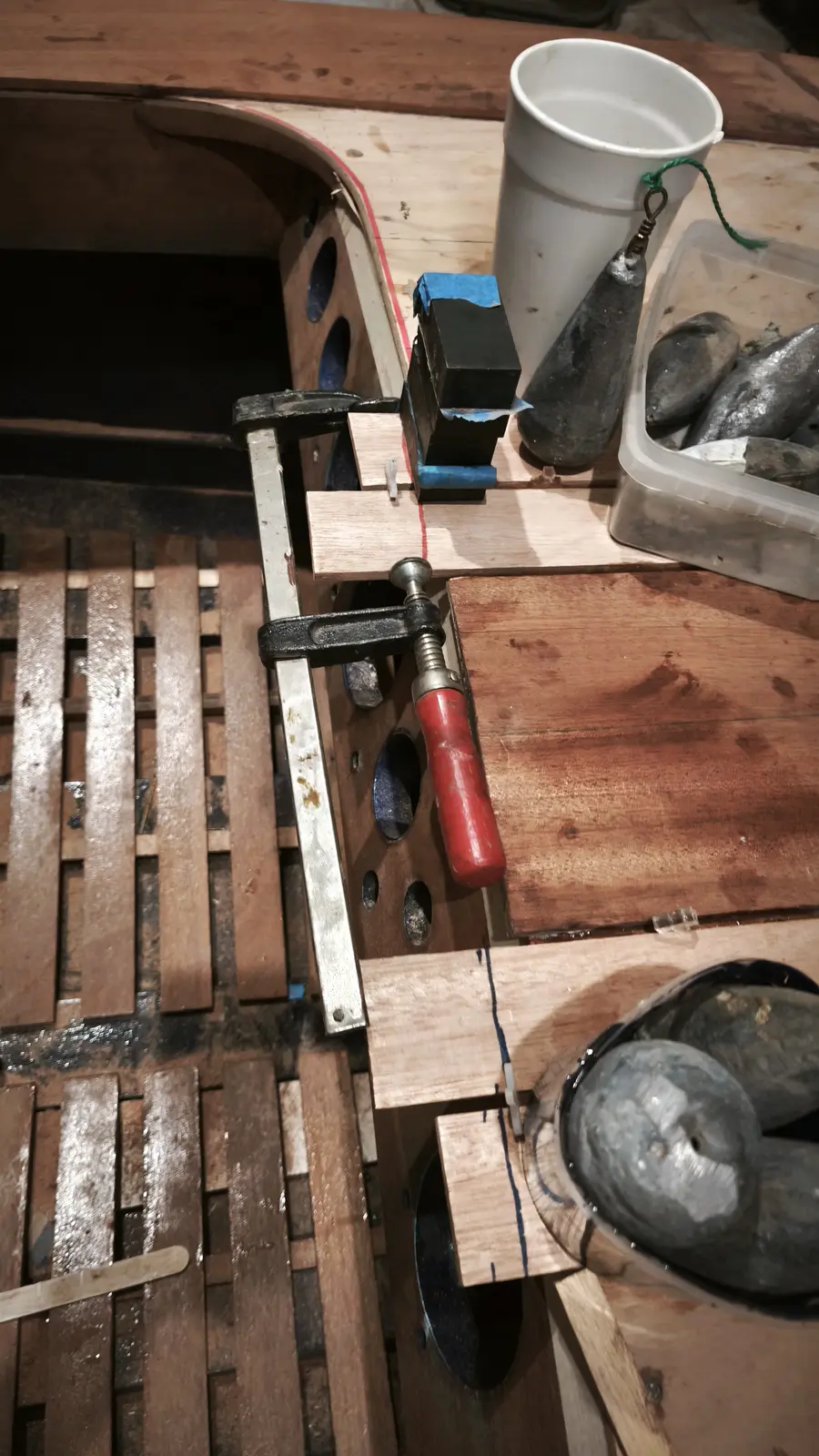
To glue the two small pieces in line I used guides. Having measured and found the right positions, I put guides either side so the pieces could not move. Once I had them clamped I took the guides off so they would not stick in the resin that squeezed out.

The two small pieces forward and aft of the locker were glued first. I want to think first about exactly how the various stainless fittings for the locker will go in (the catch and so on) and then glue them.
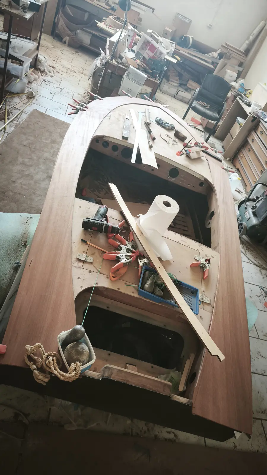
A photograph of the finished result after gluing all the sipo pieces except the locker.
Once they were glued I checked the deck for symmetry at the two widest points that are created for the parallel strips that will go in. The result is more than good.

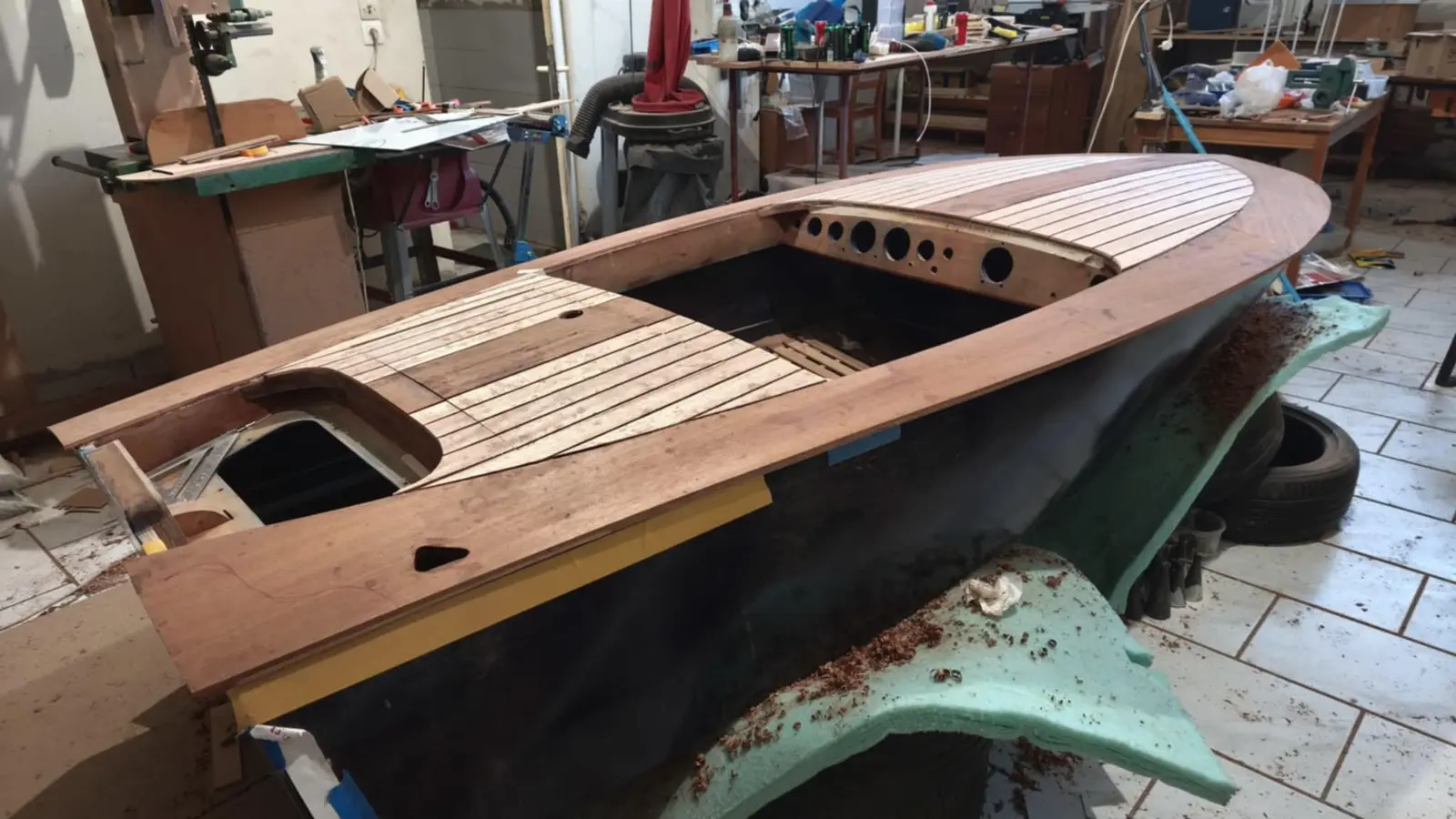
I did not have the thin strips cut and ready, so I went on to shaping the outside of the deck. I left about a centimetre of margin for the final work. I had not yet decided how the plywood and the timber would be shaped in section. See what I mean in the photographs below.

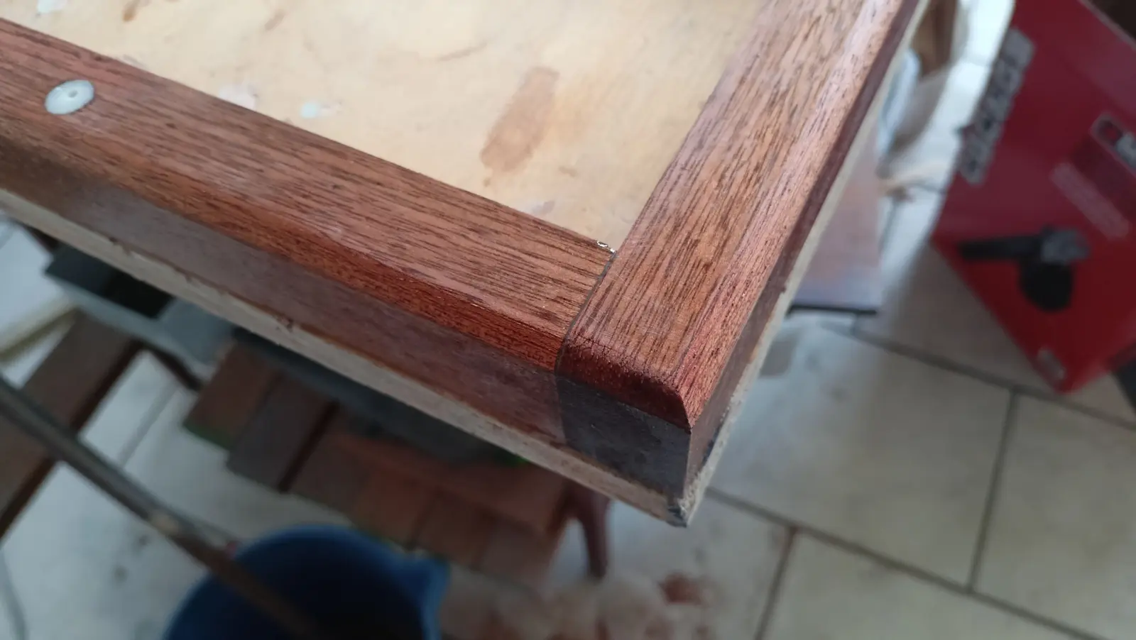
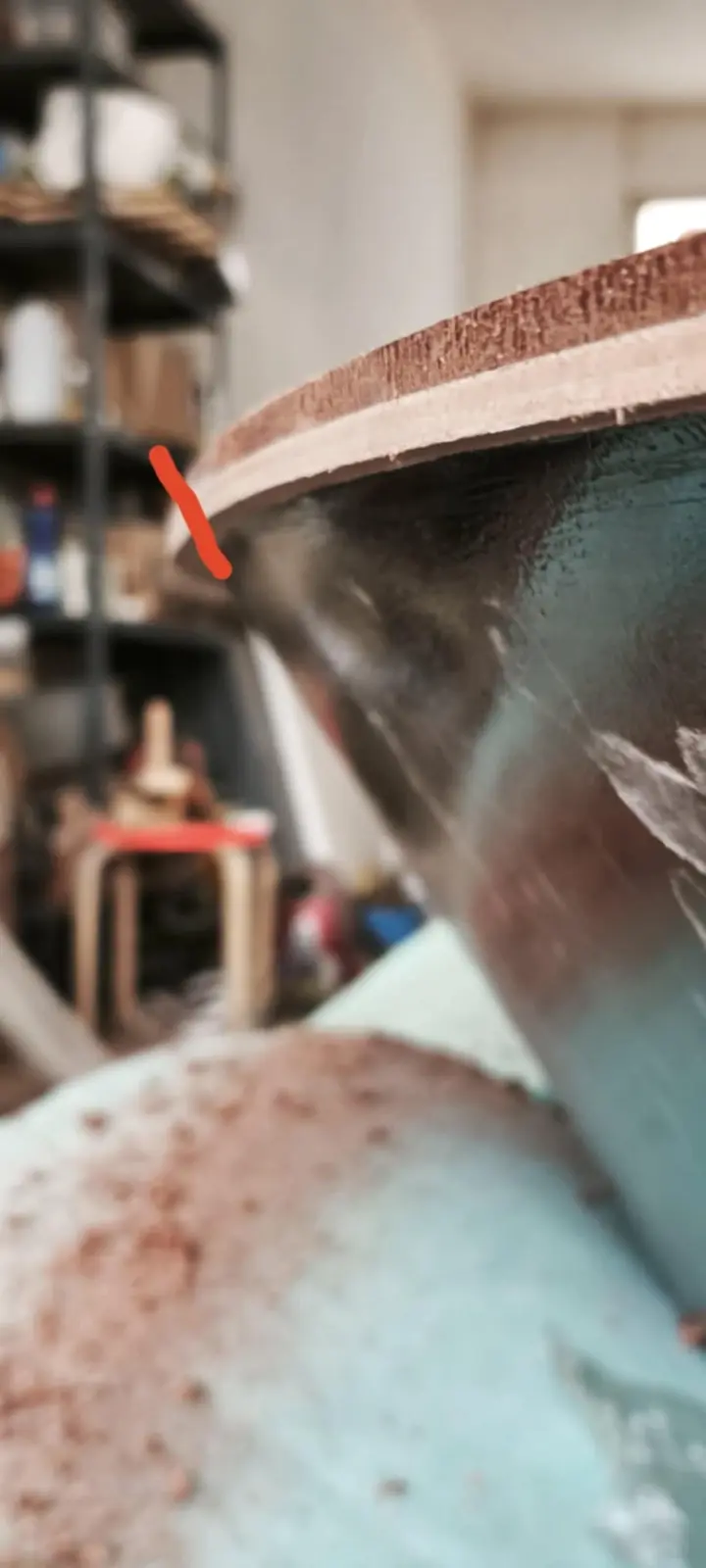
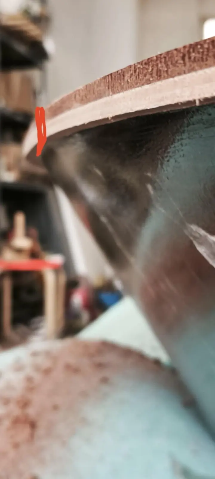
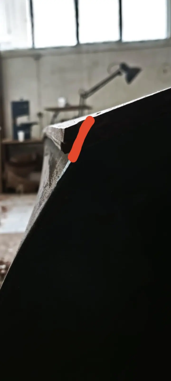
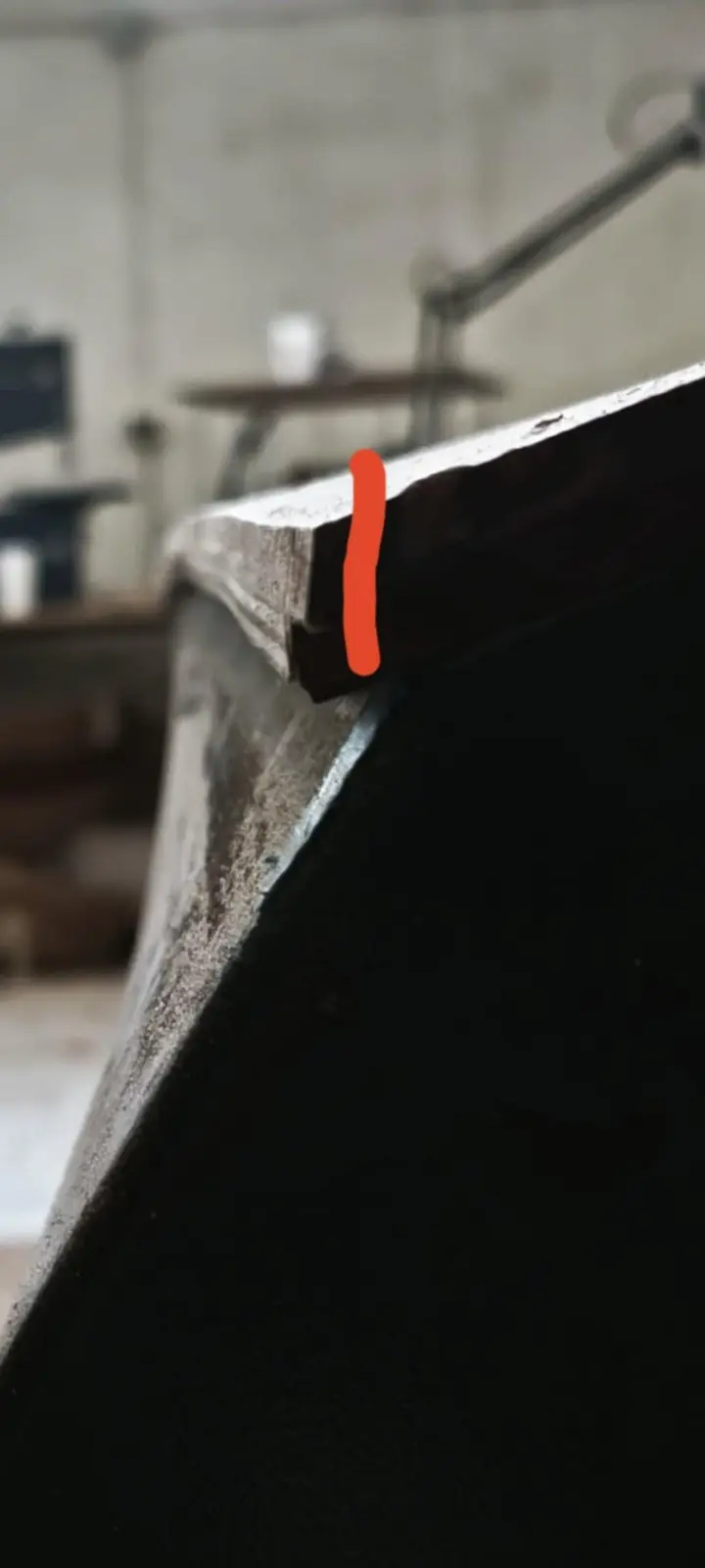
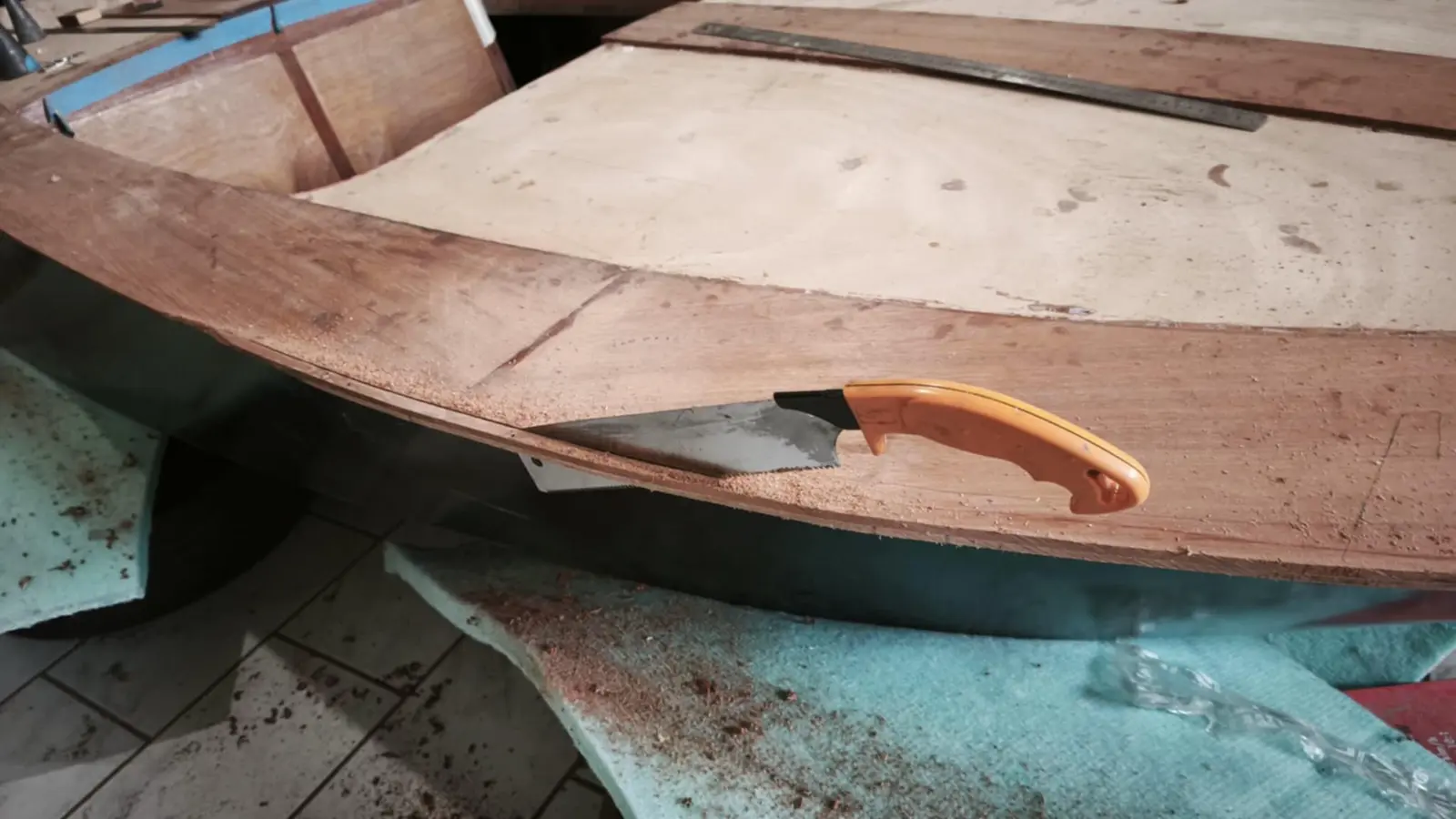
In the end I decided the cut would be vertical so I can fit a stainless rubbing strip. I also decided not to cut it flush with the hull but to leave a little timber overhanging, so that if it gets knocked against a quay at some point I have some margin to reshape it, taking a little more off.

I started with the saw to take off the bulk and carried on with a plane.

Work started on the thin strips.

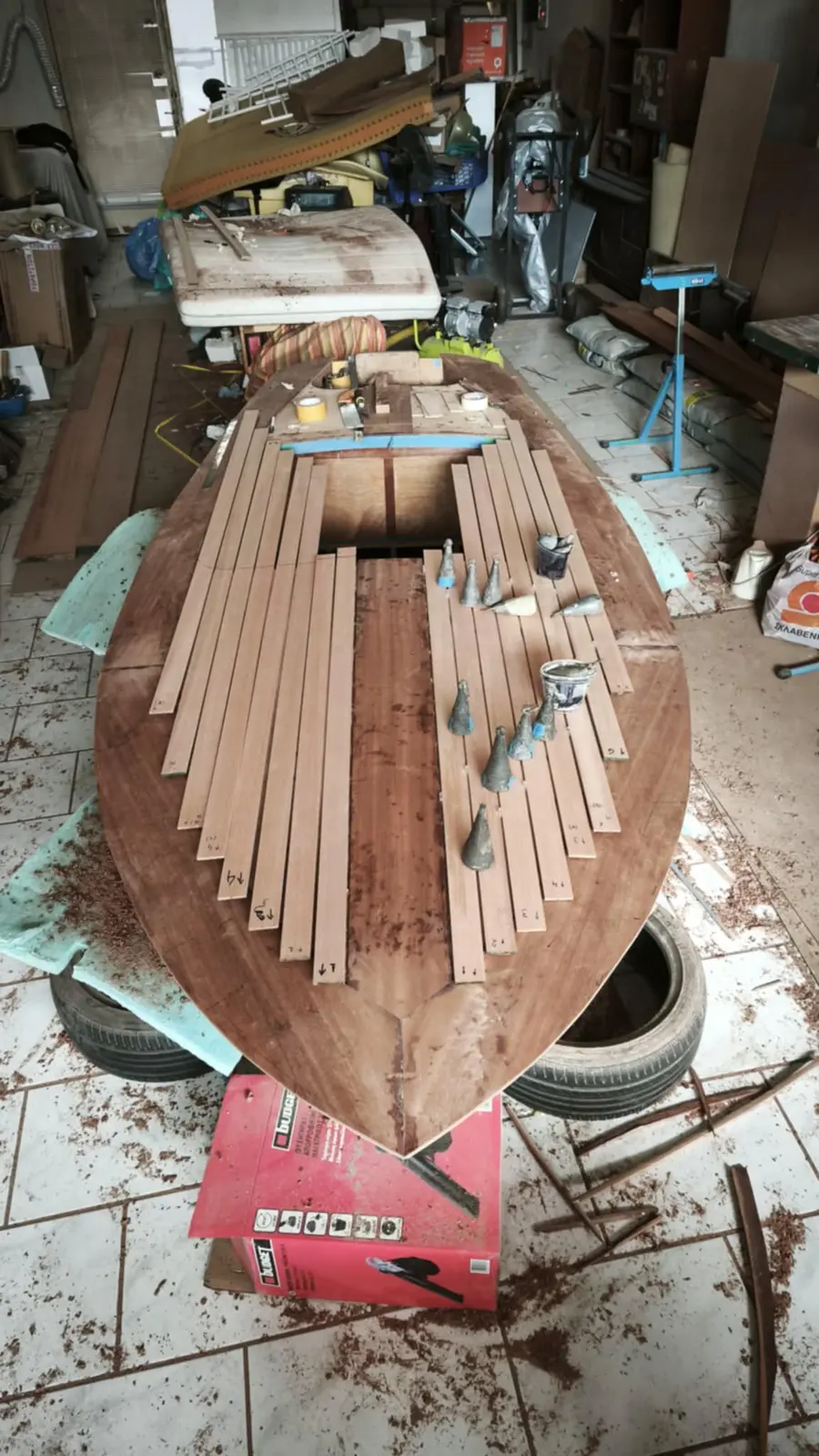
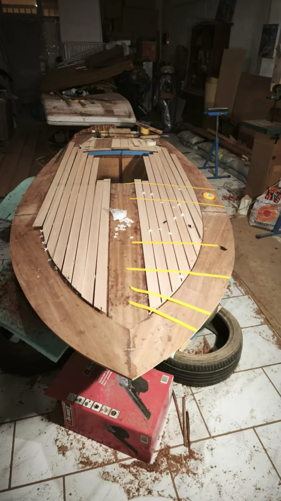
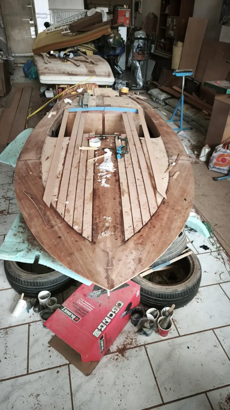
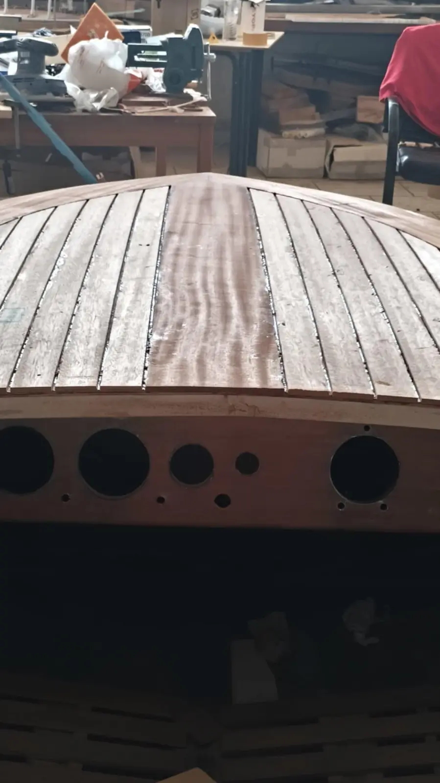
I decided to use 8 thin strips at the forward end. Aft it comes out at 7. The width was worked out like this. I want the outer strip to be the same width at its end as the others, so it looks right. With 8 strips I will have 9 gaps to be filled with 5 mm of epoxy. So 43 minus 9 x 0.5 = 38.5.

38.5 divided by 8 = 4.81 cm. The piece opposite, which is 2 mm narrower, will effectively be made with strips of the same width. The two millimetres will be spread evenly across the 6 inner strips.
Aft, that width fits perfectly, as you will see in the photographs. If it had not fitted I had decided to reduce the width of the outer strip a little.

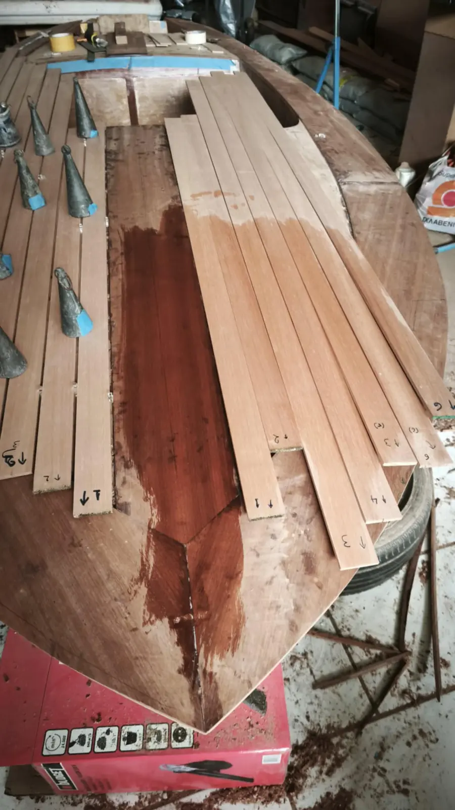
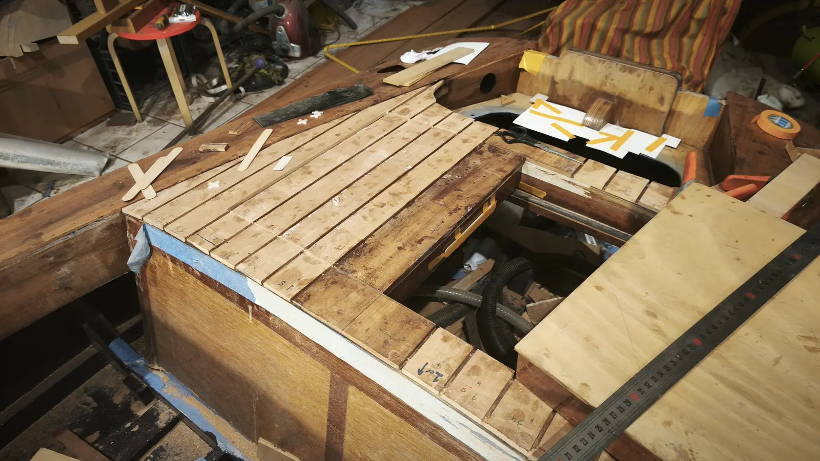
The timber was cut. The pieces were laid on the boat to match them for colour between left and right. Each piece was cut into 3. The first two from each were placed one left and one right (bookmatched). In the end that is not really necessary, as they are all the same colour and do not have much figure.

Alongside the forward end, gluing started on the central pieces at the locker. For gluing I first used the guide to hold the line, but the timber was not bedding well even though I had put weights on top. So I used clamps, being careful the timber did not kick out.

Each time, one strip of timber is glued on the left and one on the right.

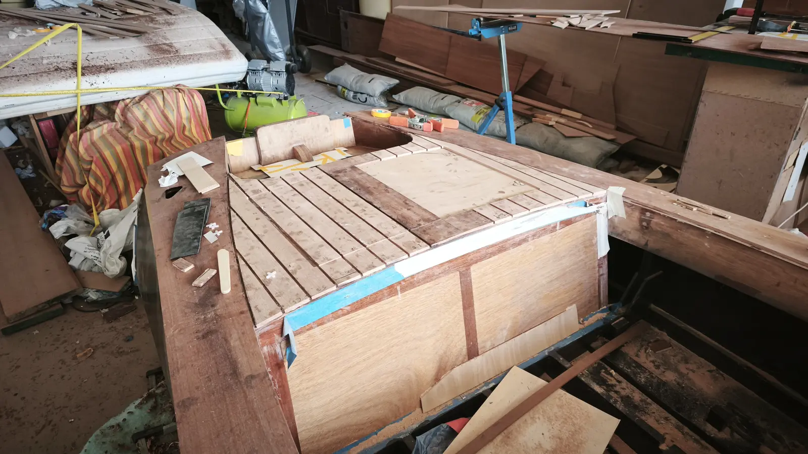
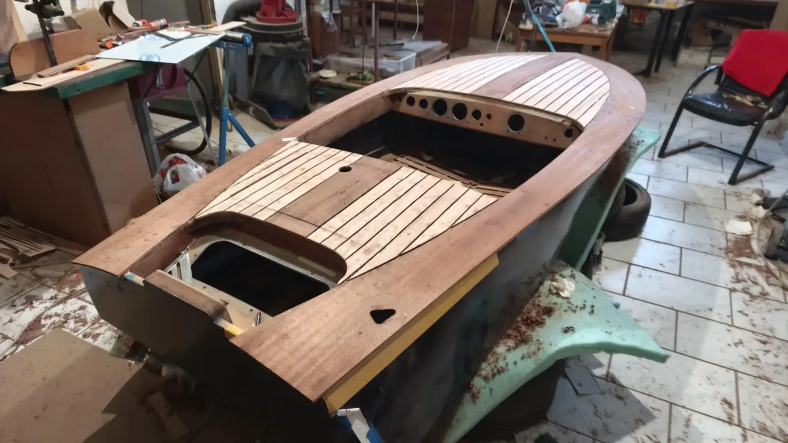
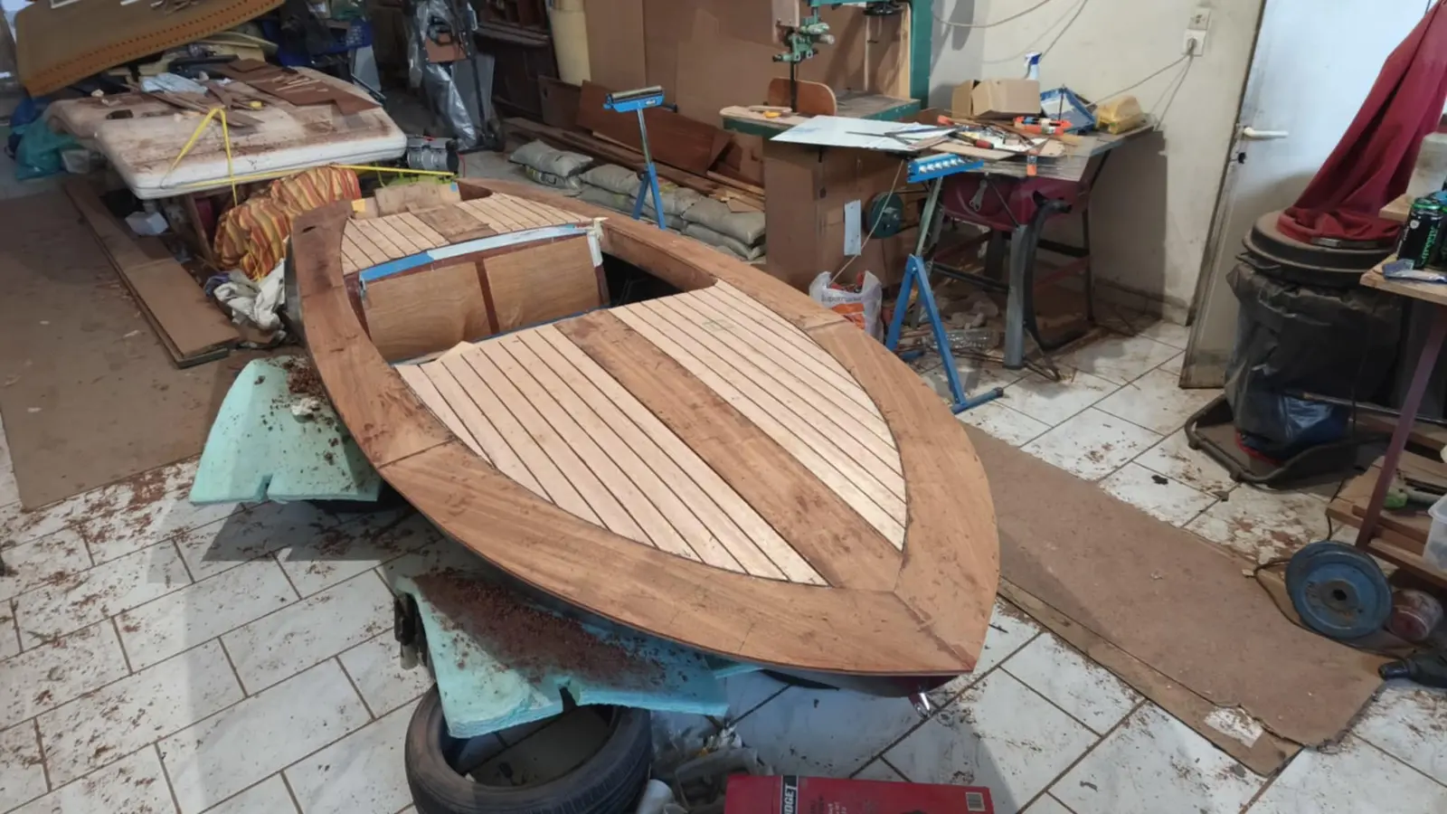
The forward end is almost finished. Aft, because of the locker, more pieces have to be glued in smaller sizes.

Some photographs of the gluing in the middle section.

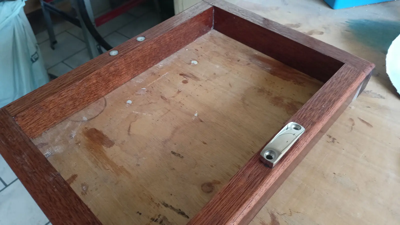
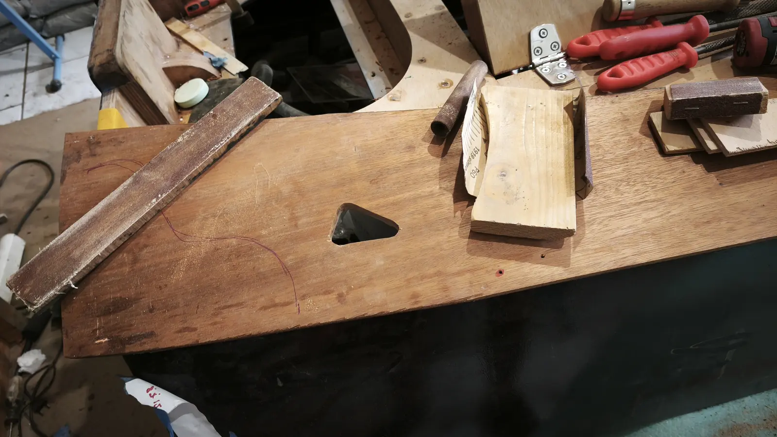
Then all the locker pieces were glued and the hole was cut for the handle. The handle needs a good deal more work from underneath to fix it properly with screws.

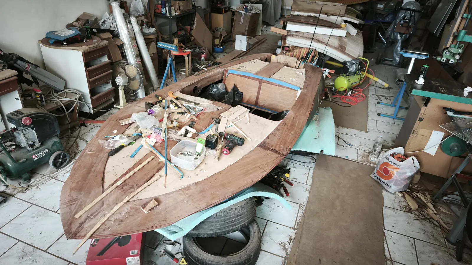
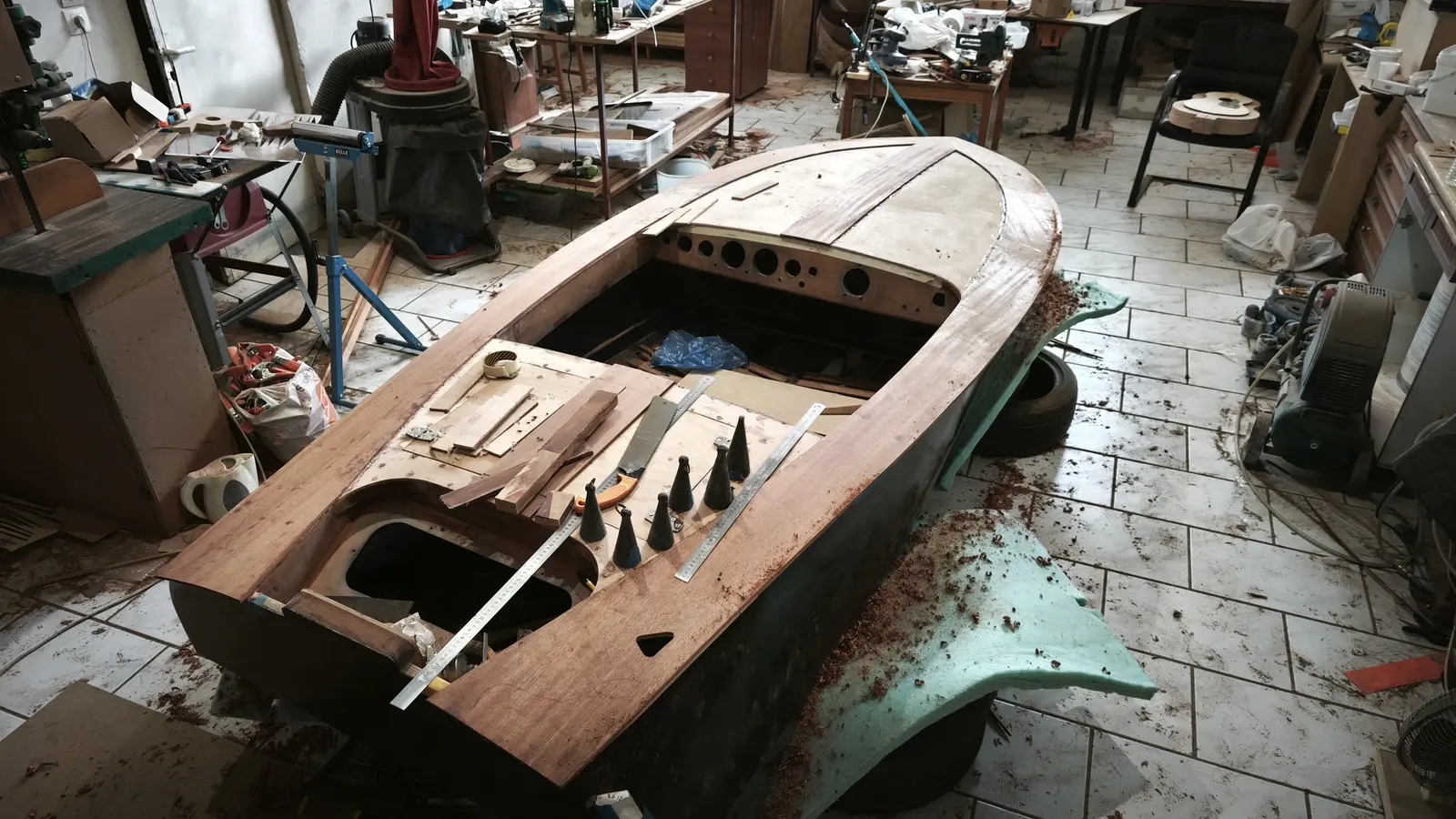
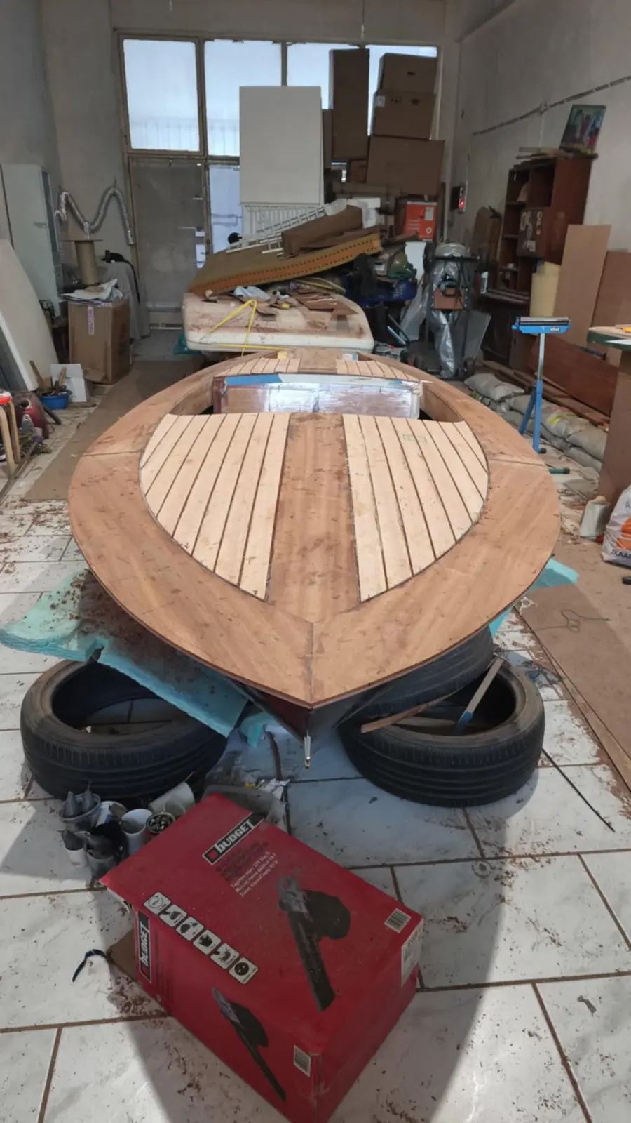
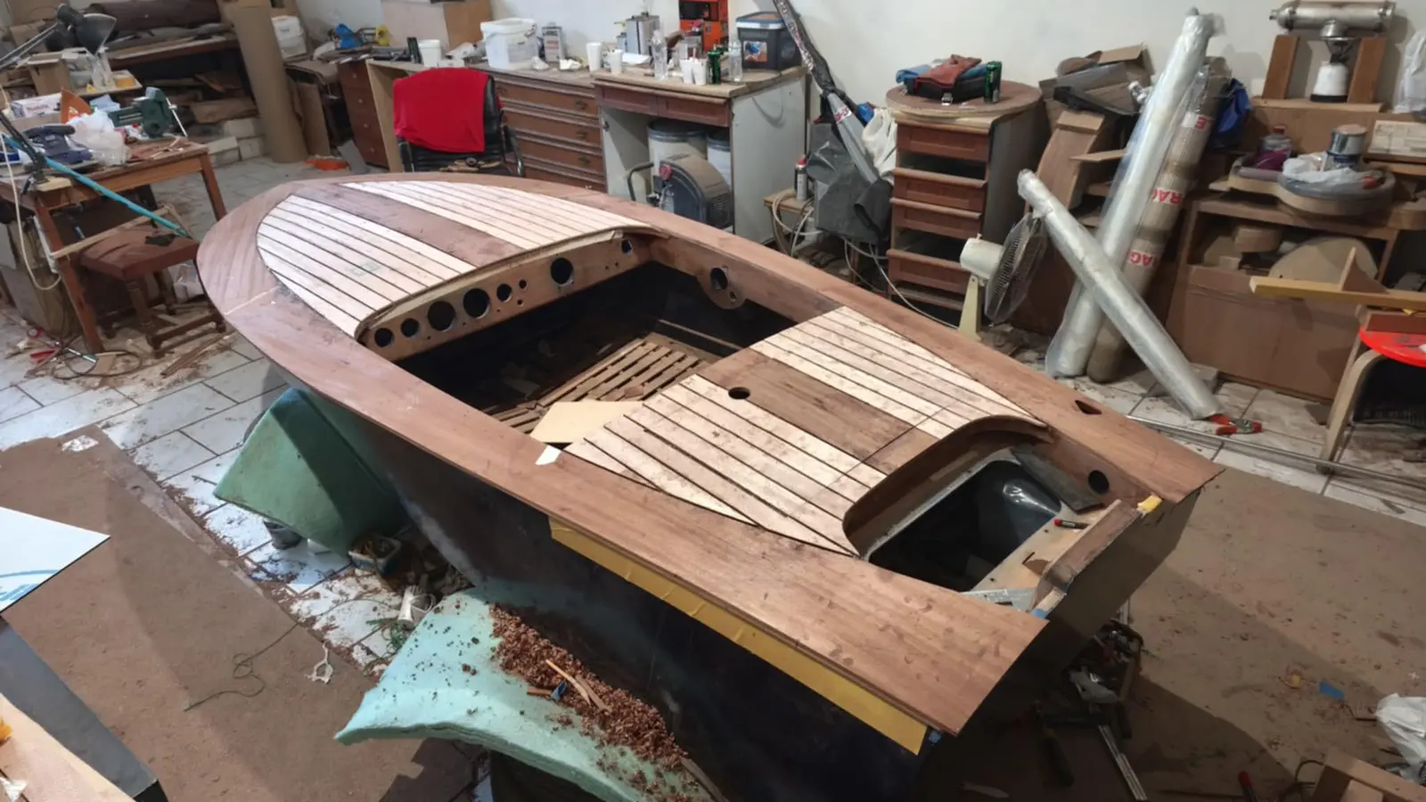
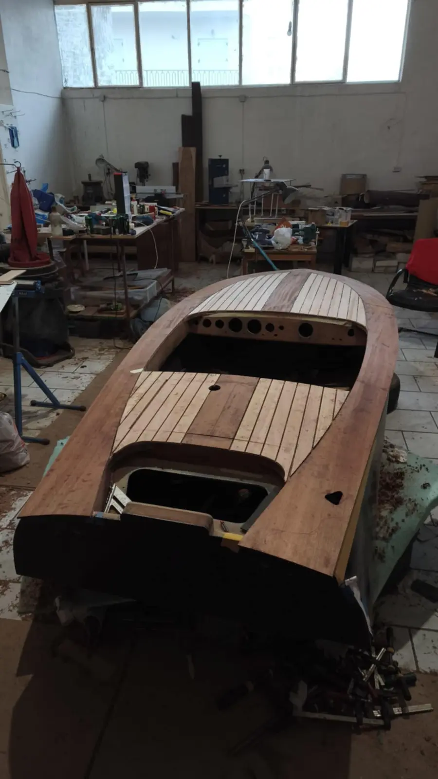
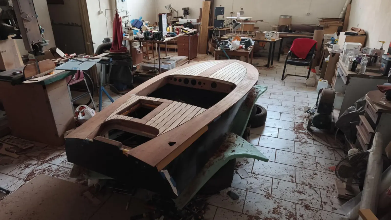
Some photographs of the boat with the timber all glued on. It has not been shaped yet.

Link

Gluing mahogany onto the aft locker

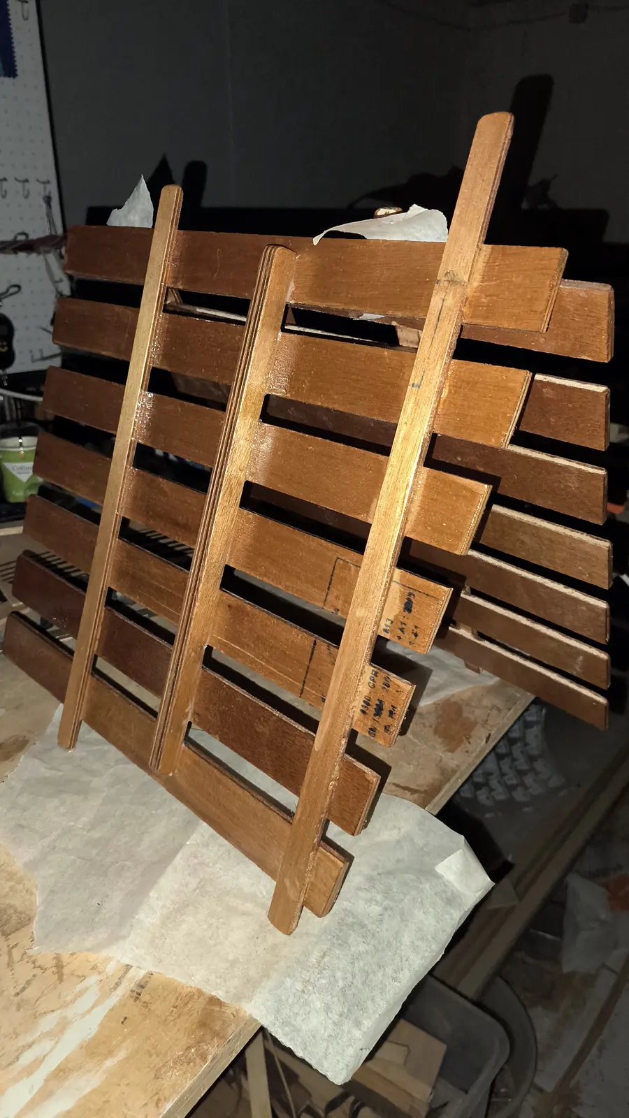
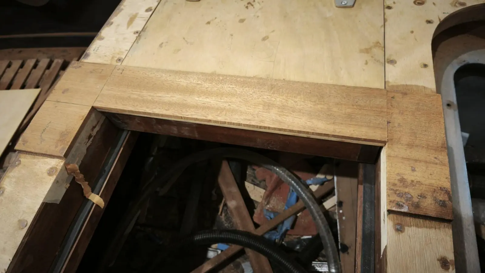
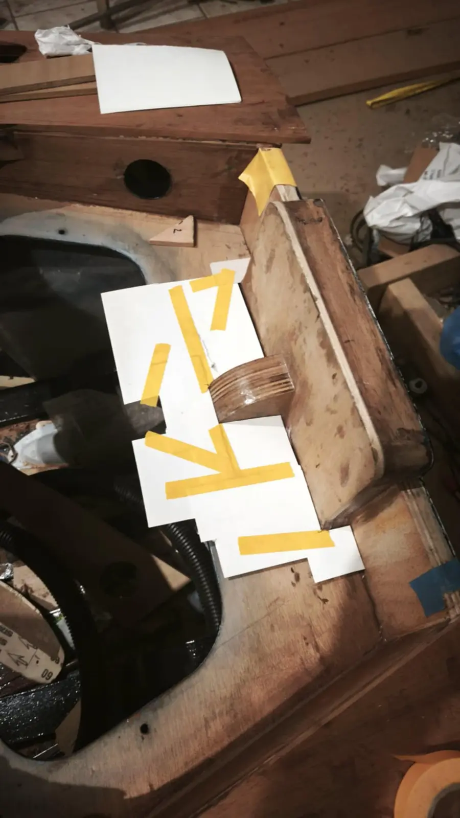
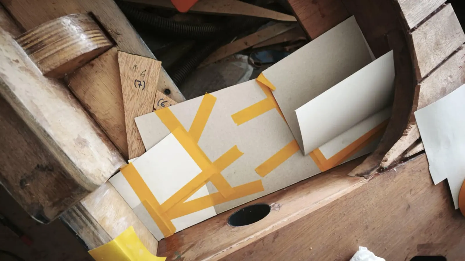
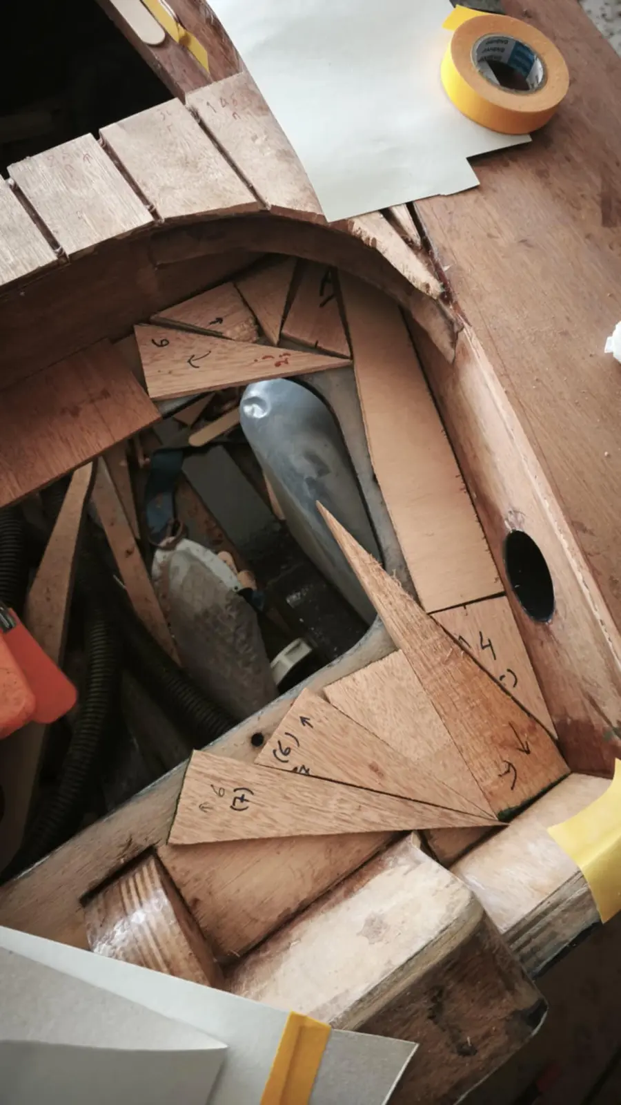
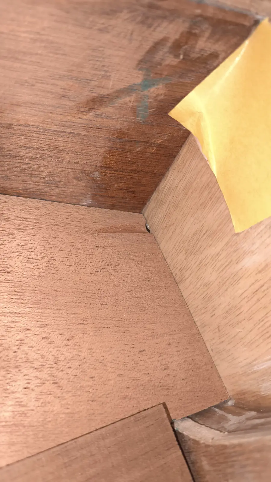
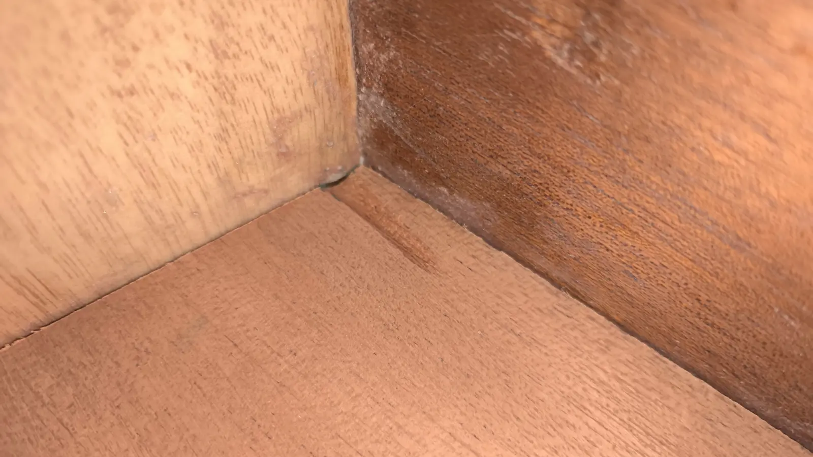
I decided to glue only the dark mahogany onto the aft locker. To take the measurements for the pieces, and because the various pieces glued to each other are not square, I laid on thin sticks of the same thickness as the timber to be glued and then stuck paper between them to build up the shape I wanted.

The finished result is shown in the photographs below. Small holes were drilled in the transom to let water out, and the recess shown was made on the inside. A slope had been allowed for in the plywood so that water is led to the two corners.

The inner part of the locker was finished too. It has not been fully sanded yet. The stainless fitting that will hold it has been designed and will be sent for laser cutting.

What it cost

€8,936.64
€7,767.94
Into the boat
€1,168.70
Tools & gear
ItemQtySupplierCost
Timber for the building base n/a n/a €120.00
Glen-L Squirt plans 1 n/a €78.00
Screws and nails n/a n/a €183.23
Plexiglass template stock, laser cut 1 n/a €43.00
Plywood for the frames and transom 2 x 7 mm, 1 x 20 mm n/a €160.00
Sapele for the frames 3 n/a €150.00
Screws for the building base n/a n/a €12.00
Epoxy resin 5 litres n/a €222.00
Microfibre filler 10 lt n/a €14.67
Fiberglass cloth 20 n/a €44.00
More marine plywood 4 x 6 mm n/a €236.00
Rollers and sundries n/a n/a €35.00
Brushes n/a n/a €14.00
Silicon bronze screws from England, No. 2 n/a n/a €50.00
Galvanised carriage bolts n/a n/a €10.00
Tools: router, sockets, drill bit n/a n/a €110.00
Disposable gloves n/a n/a €10.00
Packaging bags for steam bending n/a n/a €15.00
Steamer n/a n/a €70.00
Alignment laser n/a n/a €22.00
Forward mooring cleat 1 n/a €15.00
Aluminium angle for the table saw n/a n/a €13.00
Scales n/a n/a €6.00
9.5 mm drill bit for the cleat n/a n/a €5.00
Forward mooring cleat n/a n/a €14.00
Microballoons n/a n/a €9.70
Speedometer n/a n/a €80.00
Battery gauge n/a n/a €40.00
Horn and button n/a n/a €76.00
Spiral screwdriver n/a n/a €32.00
Aft mooring cleats 2 n/a €22.00
Brushes and rollers n/a n/a €30.00
Cleats 2 n/a €18.00
Sipo, 3350 x 170 x 65 0.037 m3 n/a €80.00
Joiner's fee n/a n/a €150.00
Brushes 60 n/a €37.00
Cable ties, 37 cm 1 pack n/a €7.00
Spring clamps 70 n/a €63.00
Sipo, 3350 x 140 x 65 0.03 m3 n/a €60.00
Brushes 60 n/a €19.00
Corrugated card 8 m n/a €5.00
Stainless coffee cup holders 2 n/a €7.50
Fuel gauge 1 n/a €9.00
USB and 12 volt socket n/a n/a €6.00
Screws and plastic washers for planking 100 + 100 n/a €7.00
Screws and plastic washers for planking 100 + 100 + 100 + 50 n/a €15.00
Resin mixing sticks 100 n/a n/a
Epoxy resin 5 litres n/a €223.00
Epoxy primer 1 litre n/a €56.15
Timber for the second building base n/a n/a €30.00
Fiberglass cloth, 213 g/m2 n/a n/a €123.70
Roller trays, 20 mm 2 n/a €3.00
Epoxy fairing filler n/a n/a €24.00
West System resin rollers 8 n/a €65.00
Resin rollers, 9 in 2 n/a €18.00
Double-sided tape n/a n/a €1.00
Dowels, 10 mm n/a n/a €4.00
Chandlery: lights, switch, pumps n/a n/a €262.60
Yamaha 25 hp GES EFI outboard 1 n/a €4,340.00
Flush-mount control box 6X3 1 n/a €170.00
Epifanes Polygloss Britannia Blue 3 n/a €135.75
Hempel epoxy filler 1 lt n/a €68.50
Hempel light primer 0.75 lt n/a €40.00
Thinner 0.75 lt n/a €18.00
Brush 1 n/a €6.50
Rollers 2 n/a €6.40
Rollers 3 n/a €7.50
Mixing pots 15 n/a €10.00
Rollers 14 n/a €8.00
Black brush 1 n/a €5.00
Water containers 3 n/a €19.50
Water container 1 n/a €8.00
Box section for the outboard dolly 6 m n/a €18.00
Dolly wheels, lower 2 n/a €18.00
Dolly wheels, upper 2 n/a €30.00
Machine shop, drilling the dolly axle n/a n/a €10.00
Locker catch 1 n/a €35.00
SeaStar TFX N.F.B. 4.2 steering helm 1 n/a €239.90
SeaStar SSC62 TFX Quick Connect steering cable, 16 ft 1 n/a €133.00
SeaStar TFX NFB 90 degree bezel kit 1 n/a €20.00
Osculati steering wheel 1 n/a €132.00
Fairleads 2 n/a €20.00
Locker catches, fore and aft 2 n/a €14.00
Pump outlet fittings 2 n/a €24.00
Brushes, 2 cm 40 n/a €14.00
Forward deck cleat 1 n/a €25.00
Fuel vent 1 n/a €30.00
Silicon bronze screws from England, No. 3 n/a n/a €46.00
Push switches 6 n/a €36.00
Cable tie bases for the wiring 20 n/a €4.24
Horn button, No. 2 1 n/a €7.00
Double-sided tape 1 n/a €1.80