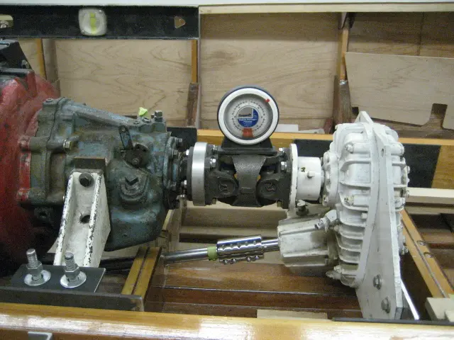
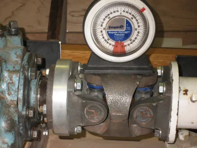
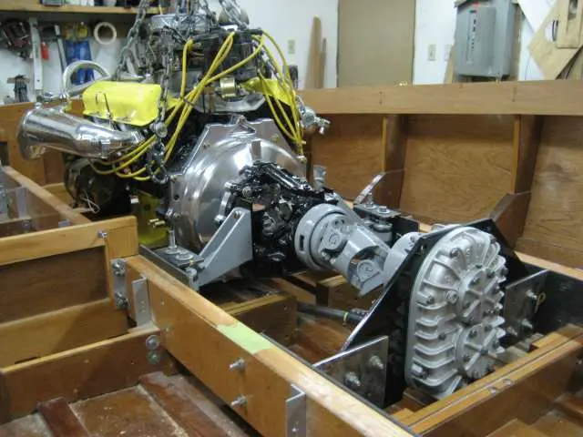
The H joint was bolted up to the transmission flange
The H joint was bolted up to the transmission flange. The v-drive was pushed back and down until the propeller shaft coupler rotated freely on the propeller shaft.
An inclinometer (angle finder) was used to set the H joint at 0 degrees. The v-drive mounts can be now be welded in their final location.
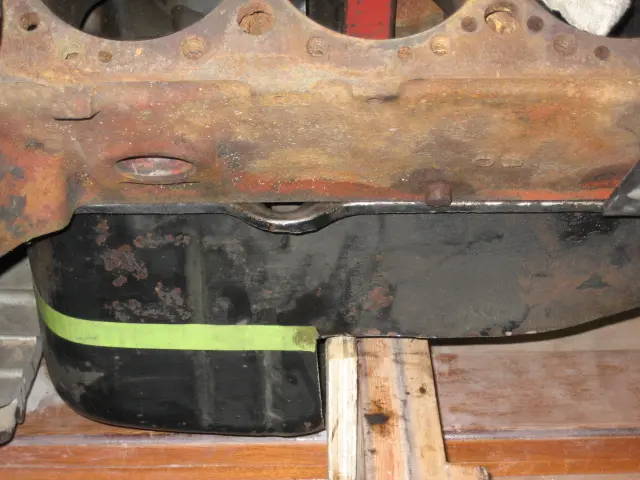
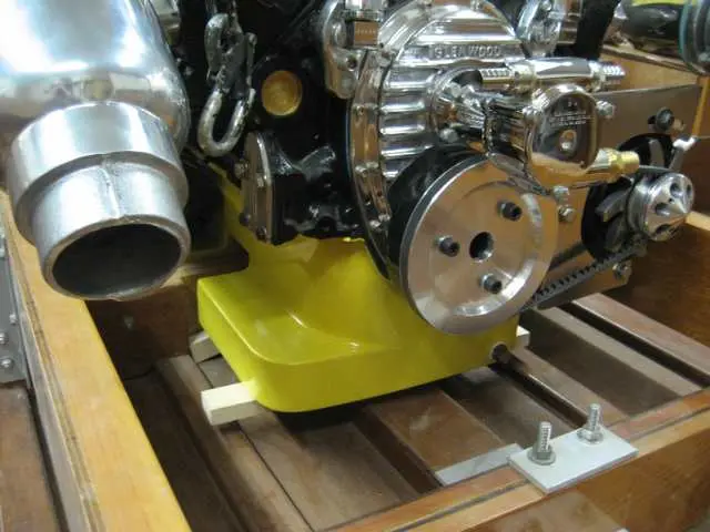
The oil pan sump was cut to move the engine 1-1/2" aft and 2-1/2" lower
The oil pan sump was cut to move the engine 1-1/2" aft and 2-1/2" lower. This will obviously generate quite a bit of work... A simpler solution would have been to either install the frame timber on the aft side of the frame or move the entire frame 2" aft. If the latter is done, the frame outline would change (frame would not be as wide) so you'd have to loft frames #0 through #5 to pick up the new chine and sheer points.
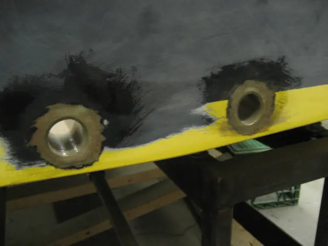
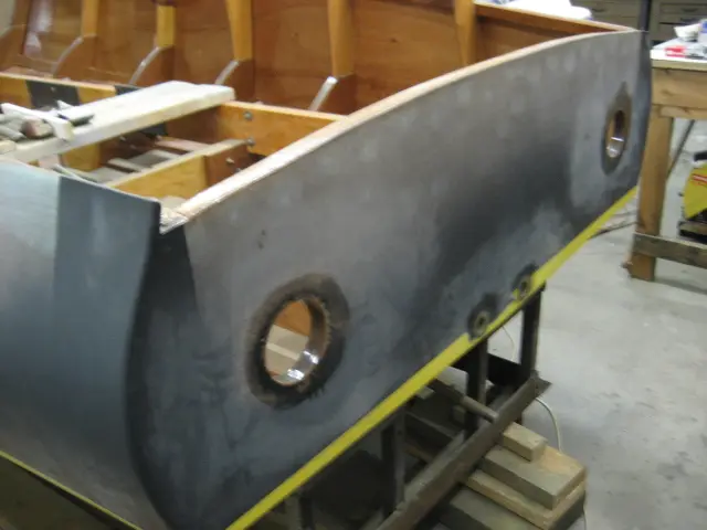
The transom drain plugs were cut out with a hole saw
The transom drain plugs were cut out with a hole saw. Fiberglass tubes were fabricated and epoxied into the holes.
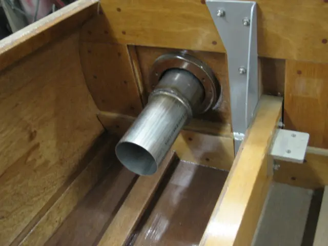
A hole saw makes quick work of cutting out the exhaust outlet holes.
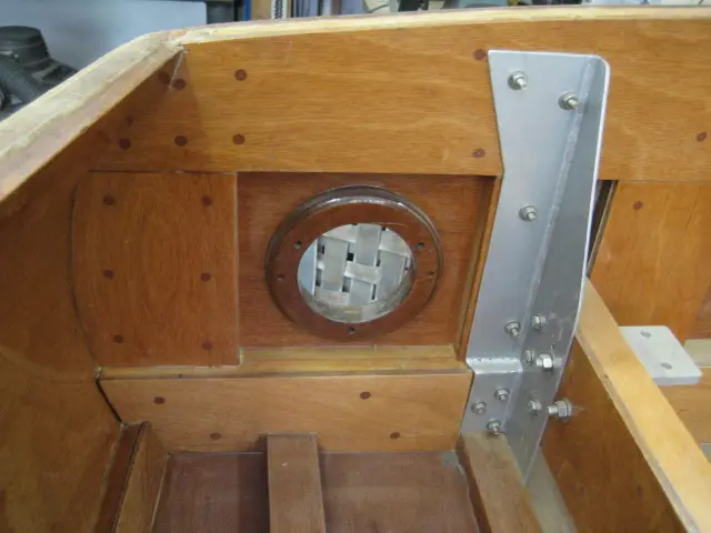
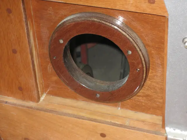
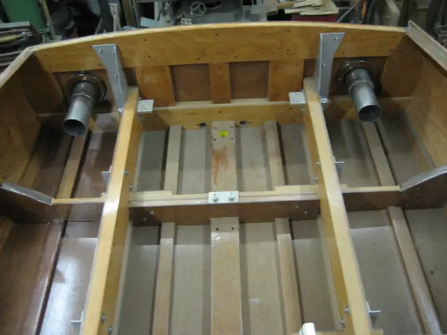
Interior view of the transom. A 3/4" marine plywood backing plate was fabricated and epoxied to the transom.
The inside lip was waterproofed with one layer of 6-1/2 ounce fiberglass cloth. The hole was drilled 1/8" oversize to allow a thick bead of sealant around the exhaust tip's circumference.
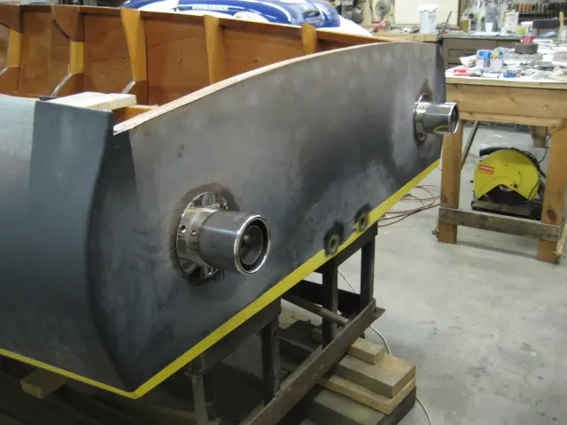
The Gibson Transom Mount Power Tip mufflers look sweet ! Click here to see the muffler specifications.
We reduced the 4" OD stainless pipe to 3-1/2".
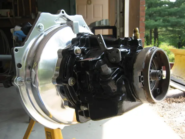
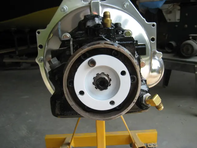
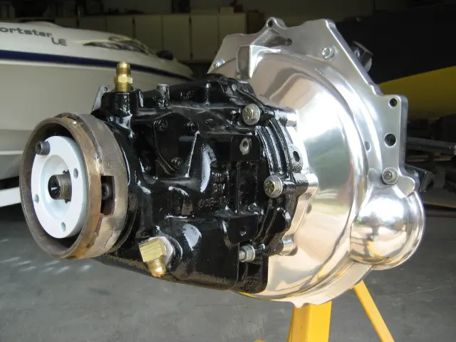
The rough-cast aluminum Velvet Drive bellhousing was brought back to life with many hours of sanding and polishing. We fabricated a torque tube guard adapter which mounts to the transnission's end-cover.
The cap bolts were replaced with hex head bolts in an effort to gain more clearance. The base was cut from a piece of 1/4" steel plate. A 1-1/2" wide slice from a 6" well casing was welded to a larger pipe which was in turn welded to the mounting plate.
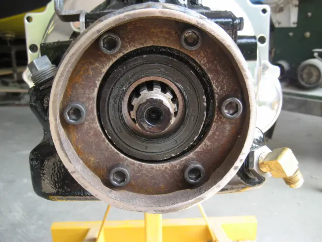
With the transmission hub installed, there's just enough room to insert a hex key to tighten the end-cover bolts.
Slots cut into both sides of the part allow access to the hub bolts. I wasn't able to find a manufactured adapter, so like many parts on the boat, you have to build your own. It won't be a real Hot Rod unless it's got a bunch of homegrown parts on it !
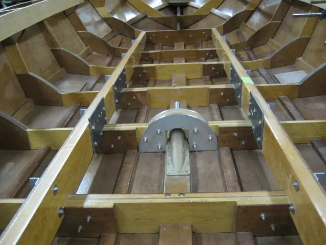
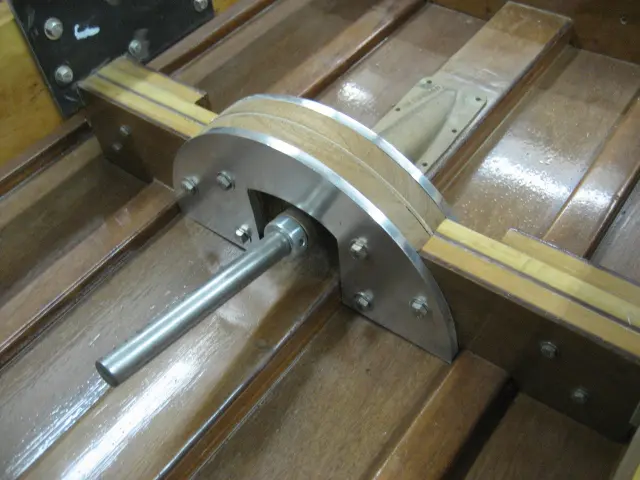
We fabricated a frame truss plate to span the stuffing box at frame # 4
We fabricated a frame truss plate to span the stuffing box at frame # 4. It's made from 3/8" thick T356 aluminum plate. The v-drive and transmission mounting plates were bolted to the stringers with 3/8" stainless steel machine bolts. Also visible in the top left corner of the photo is the carling. We'll have more pics of this after it's been all glued up.
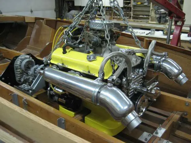
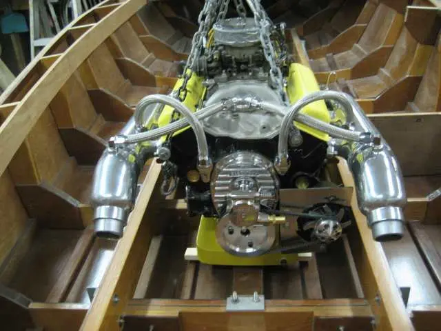
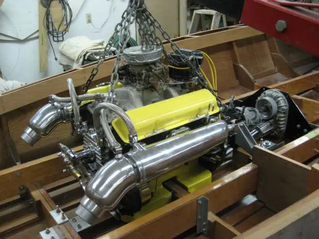
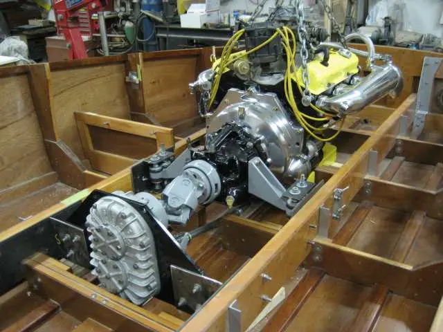
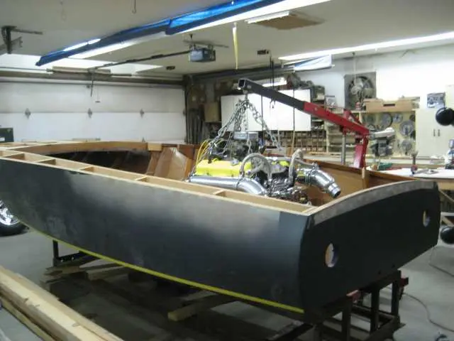
Here's the day I've been waiting for ! Engine, transmission and v-drive installed with very few issues.
We don't have enough clearance between the torque tube guard adapter and the v-drive take-off hub. The hex-head bolts used to retain the guard will have to be swapped out for flat head machine bolts.
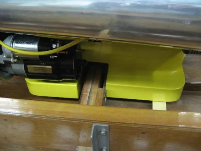
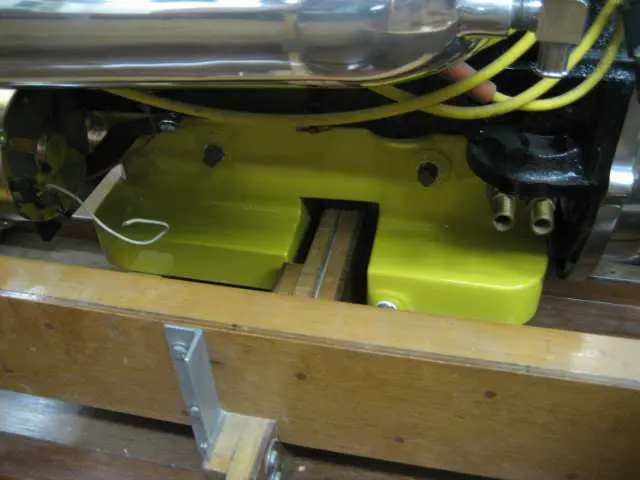
Here's a close-up of the oilpan straddling frame # 2.
Oil capacity has been expanded from 4 quarts to 12 quarts.
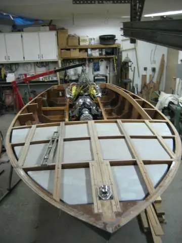
The custom oil pan lowered the engine by 3-1/2". A lot of work, but the engine is horizontal and nicely nestled into the boat.