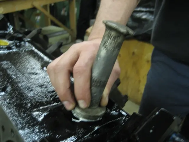
355 engine: Brass freeze plugs were coated with thread sealant and installed with a drift
Brass freeze plugs were coated with thread sealant and installed with a drift.
Hot Rod · new build
LaunchedBrass freeze plugs were coated with thread sealant and installed with a drift.
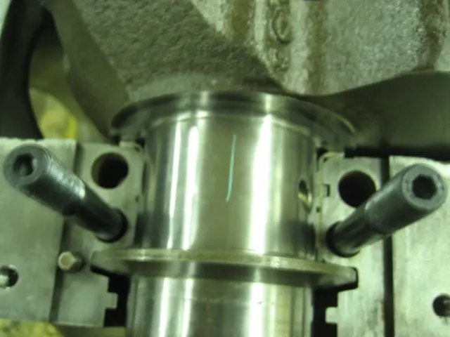
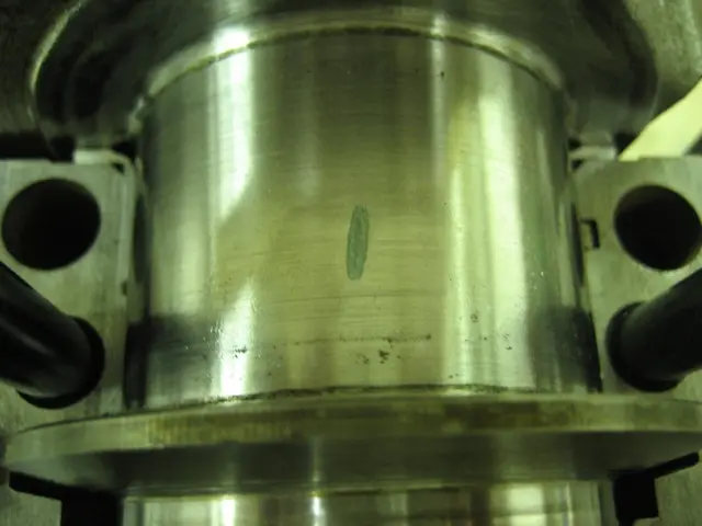
1. To check the main bearing oil clearance, we cut a plastigauge strip and placed it on the crankshaft journal.
2. The main bearing cap was lightly oiled (to prevent the plastigauge strip from sticking to it)...
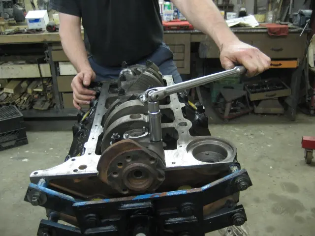
3. ... and torqued to 65 ft/lbs...
4. ... The cap was removed...
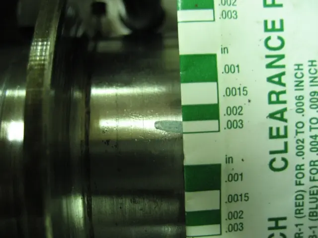
5. Clearance is determined by matching up the compressed plastigauge strip with the plastigauge kit's ruler. Crankshaft main bearing clearance: 001" -.003".
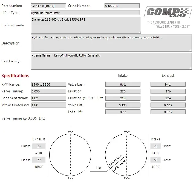
6. Hydraulic roller retrofit The early style non-roller block was upgraded to a hydraulic roller setup by using a Comp Cams hydraulic roller retrofit kit (Comp # 12-417-8, Grind Number XM 270HR). Cam specs are as follows: Gross valve lift:.495 /.503 Duration @.006 tappet lift (Intake/Exhaust): 270° / 276° Duration @.050" lift (Intake/Exhaust): 218° / 224° Lobe separation: 112° Intake Centerline: 110°
7. Image courtesy of Comp Cams. Click image to see Cam Spec Card.
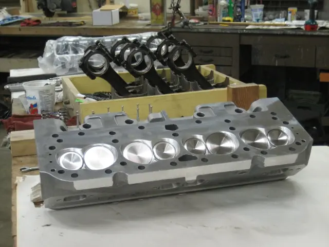
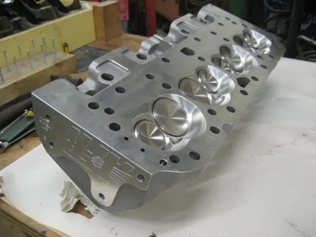
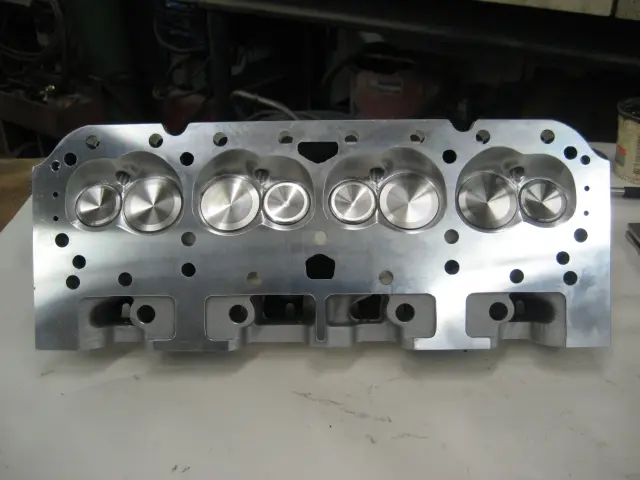
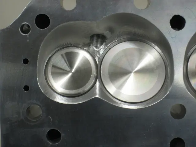
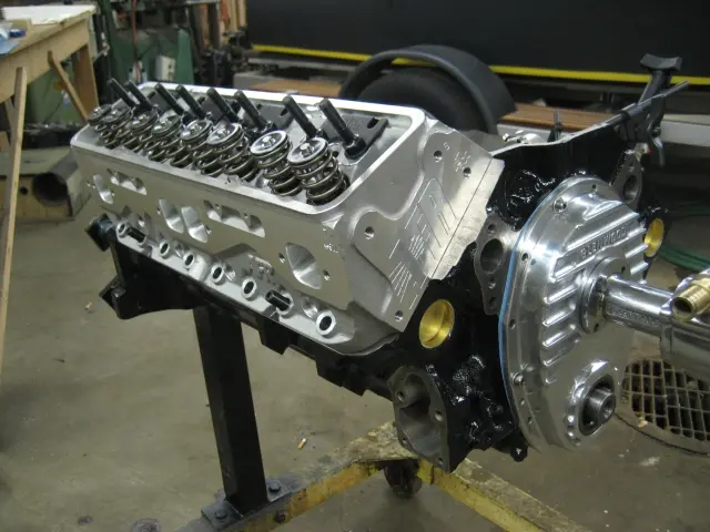
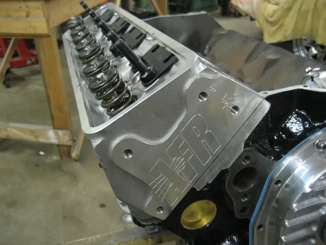
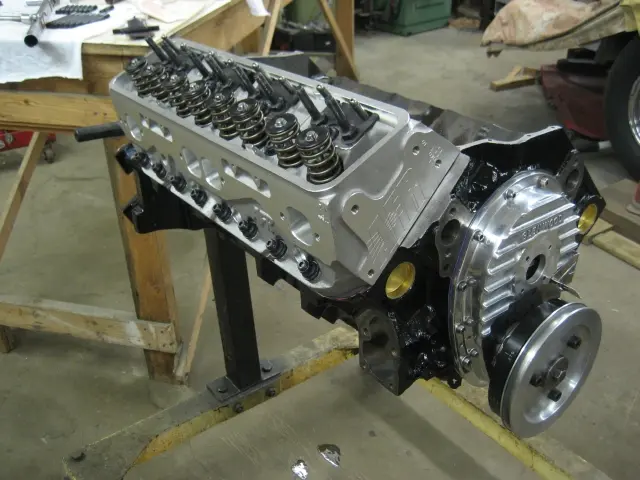
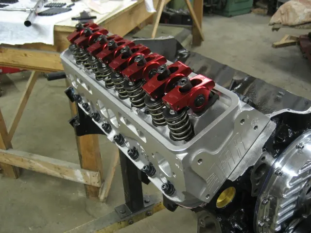
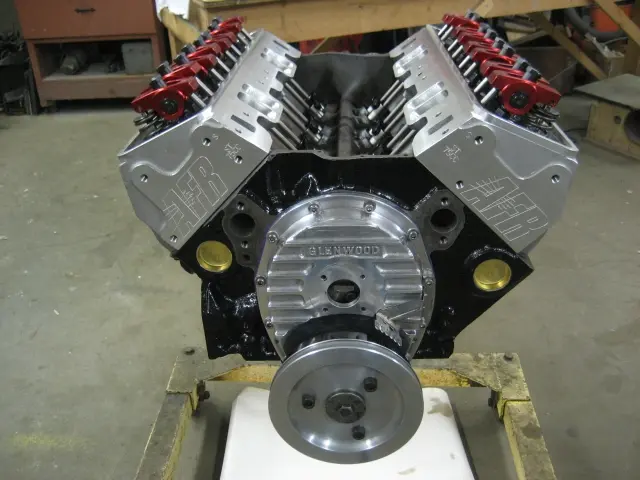
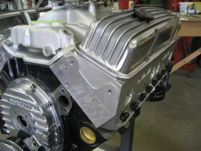
8. For this buildup, we chose to install a set of Air Flow Research 180cc SBC Eliminator Street Cylinder Heads (AFR Part # 0919).
9. The aluminum performance cylinder heads feature 180cc intake ports, a 75cc combustion chamber with a 64cc exhaust port and a 3/4" thick head deck.
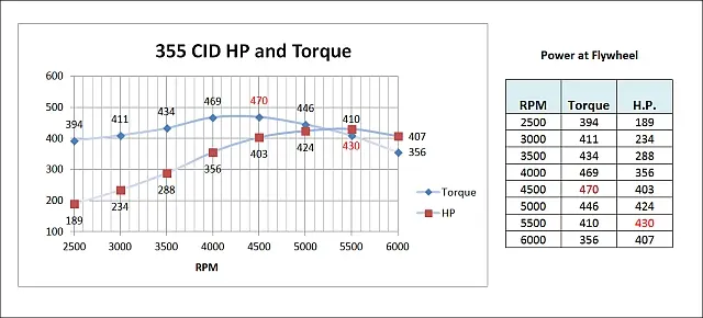
11. The engine is rated at 430 HP @ 5500 RPM. Peak torque is 470 ft/lbs @ 4500 RPM. Dyno results for a similar engine can be seen on AFR's Cylinder head dyno results page.
12. Valves are lightweight 8mm 2.020 intake and 1.600 exhaust with AFRs hardened ductile iron interlocking valve seats.
2. Pistons are TRW.030" over flat top forged units.
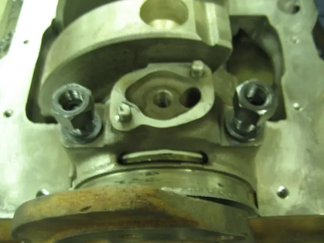
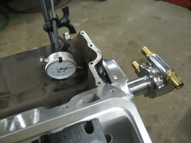
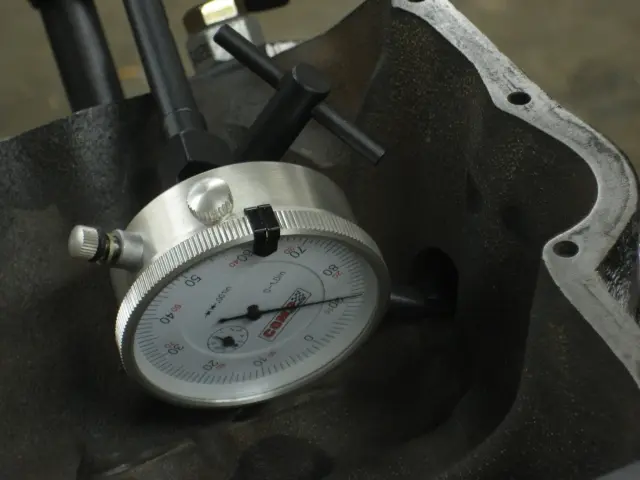
3. Checking camshaft end play with a dial gauge.
4. We had to fabricate an.048" shim to slip under the cam drive water pump drive plate in order to get the required.005" -.010" camshaft end play clearance.
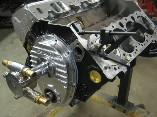
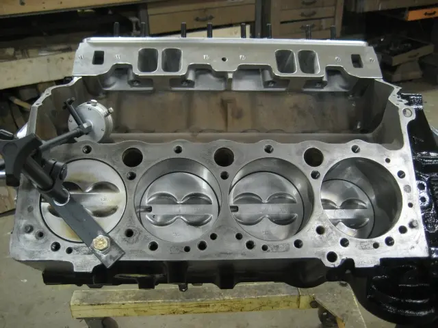
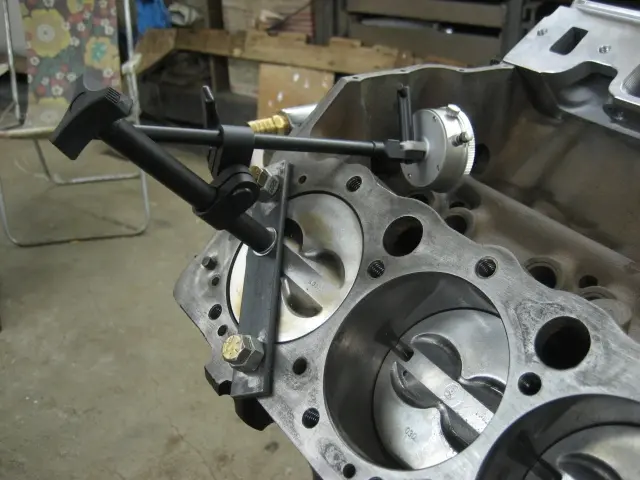
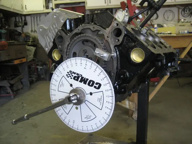
A Comp Cams degree wheel kit was used to ensure that the camshaft was installed according to specifications.
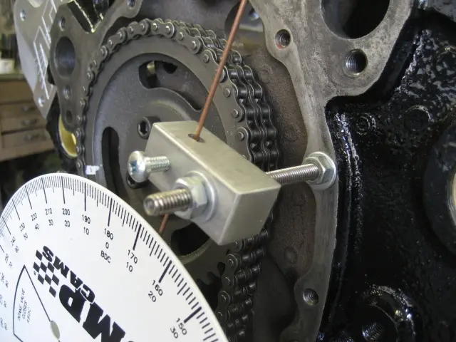
We fabricated a Top Dead Center pointer from a piece of 1/4" threaded rod, an aluminum block and a steel welding rod.
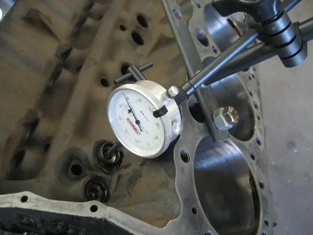
A solid lifter was inserted into the lifter bore to determine maximum valve lift and cam timing.
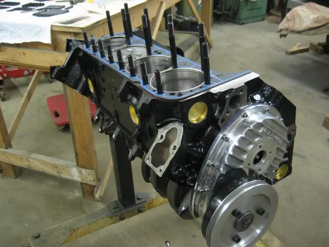
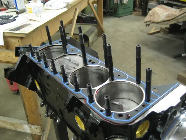
1. The stock head bolts were upgraded with an ARP head stud kit.
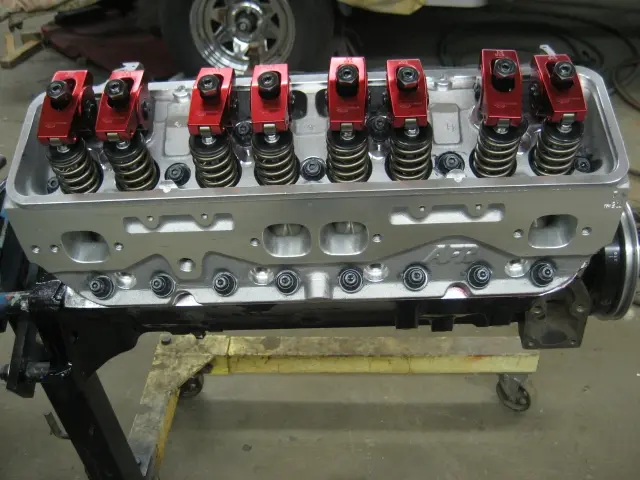
4. Comp Cams Magnum aluminum roller rockers, roller lifters and pushrods complete the valvetrain.
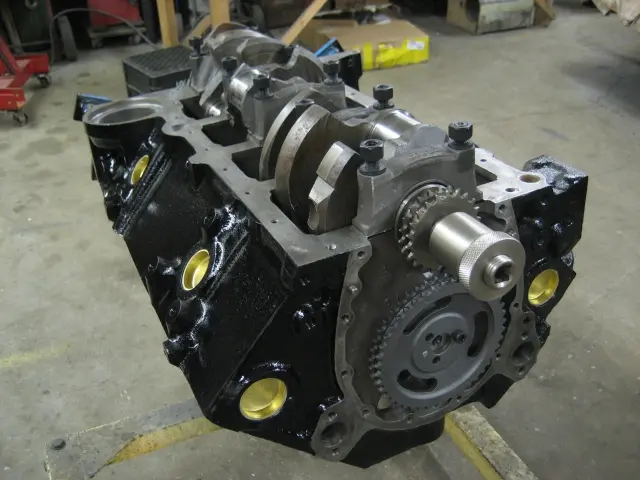
6. If you click the image to enlarge it, you'll see the drive cog for the cam drive water pump. The plate is bolted to the end of the camshaft. The timing chain cover is another Glenwood item.
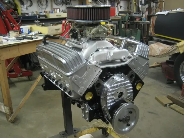
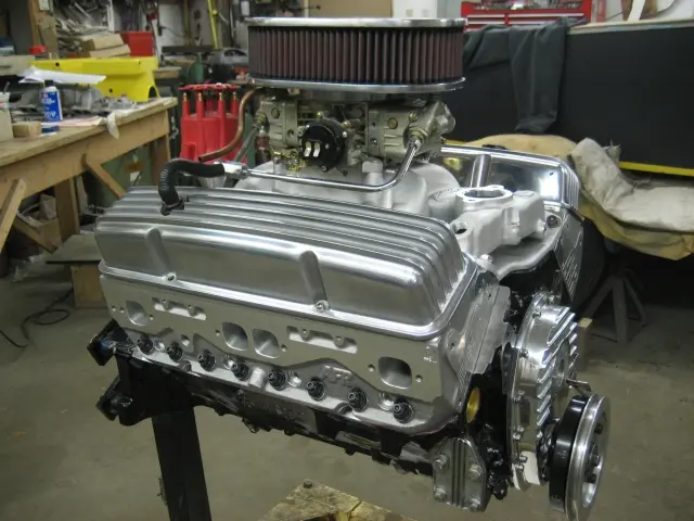
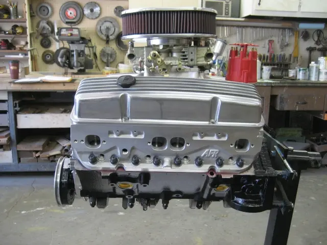
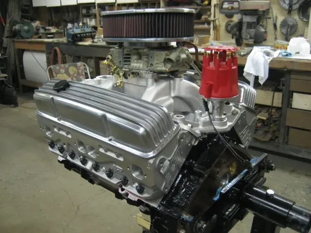
7. A Holley 600 CFM Marine performance calibrated four barrel carburetor is mounted to an Edelbrock RPM Air-Gap intake manifold.
8. The Hardin Marine flame arrestor uses a K&N air filter capable of flowing 30% more air than a stock flame arrestor.
9, 11. We've moved the engine from the assembly stand to the break-in stand. The new Edelbrock RPM Air Gap intake manifold adds several inches to the induction system's overall height. (Click the image for a higher resolution photo).
10. Ignition is controlled by an MSD billet aluminum marine distributor and digital ignition box.
Nobody else here is logging a Hot Rod yet. See the boat.