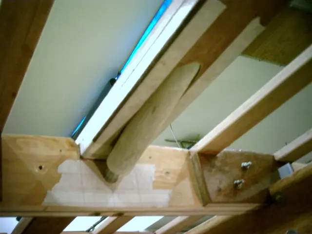
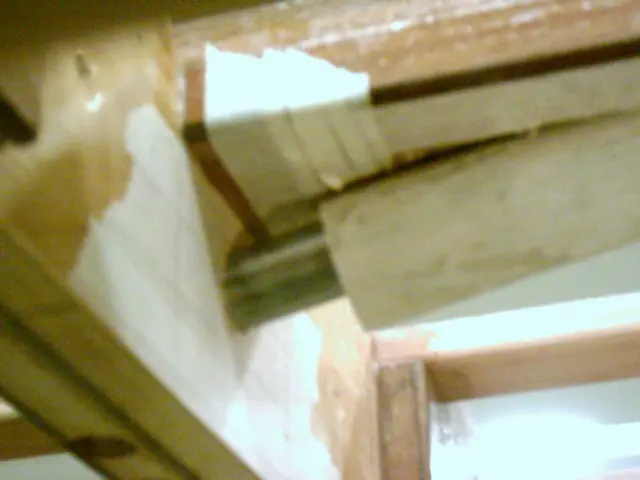
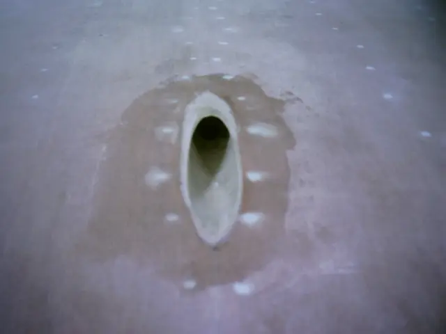
The propeller shaft hole will be drilled prior to sheeting the bottom
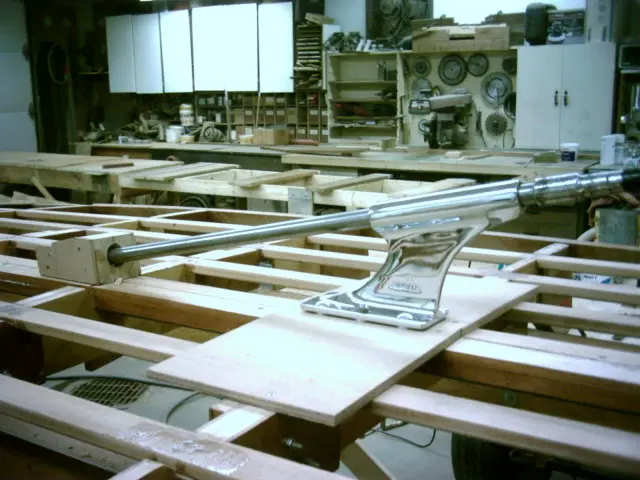
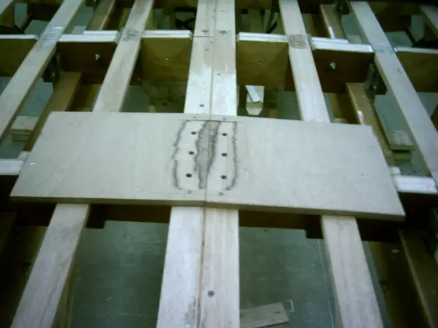
The propeller shaft hole will be drilled prior to sheeting the bottom. Two pieces of scrap plywood were screwed to the keel. Once the strut mounting holes were drilled, a stack of washers under each mounting hole was used to determine how much material had to be removed.
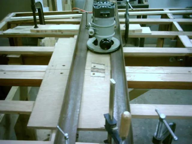
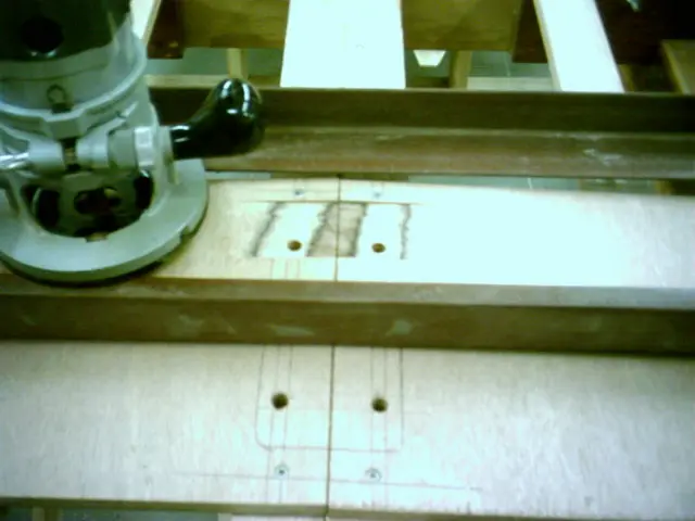
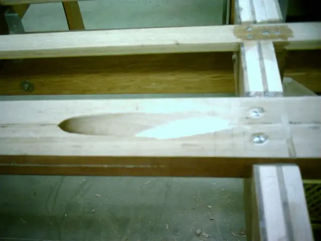
A jig was rigged up to flatten the strut mounting area. The router is run on two parallel lengths of angle iron.
Depth of cut is adjusted to remove enough material so that the strut sits flat on the plywood.
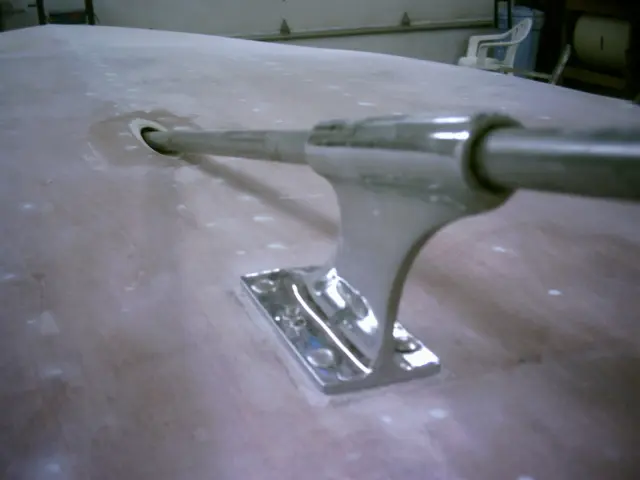
A 1/8" masonite spacer was fabricated and slipped under the strut to simulate the thickness of two layers of fiberglass
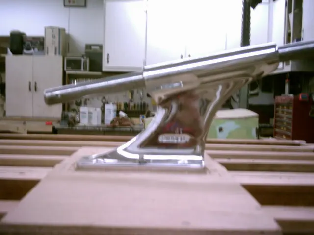
A 1/8" masonite spacer was fabricated and slipped under the strut to simulate the thickness of two layers of fiberglass cloth which will eventually cover the hull. The strut was bolted into position and an 8' long piece of 1" round bar was fed through the strut to simulate the propeller shaft.
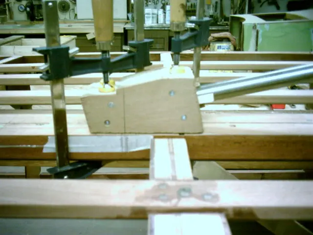
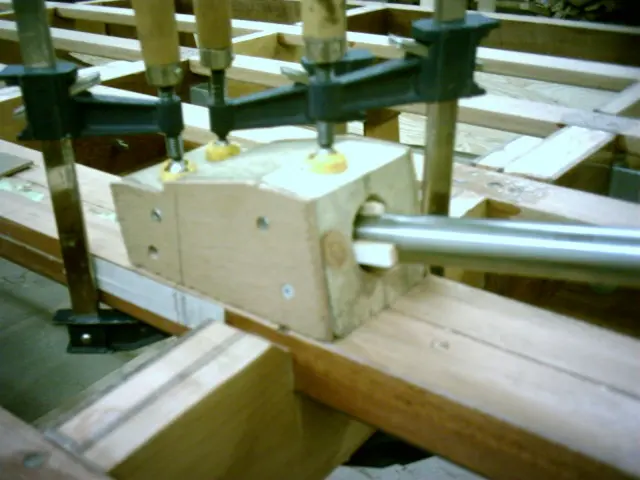
A guide block was loosely clamped to the keel. Click here to see how the guide was made.
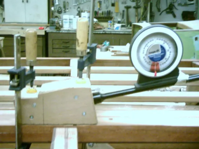
Push the shaft through the guide block until it contacts the keel and mark the point. Shim the shaft until it's centered in the guide block and mark the holesaw entry point. Clamp the guide block.
Remove the shaft and insert the boring bar, coupler and holesaw into the guide block. Use an inclinometer to verify the shaft angle is correct before drilling.
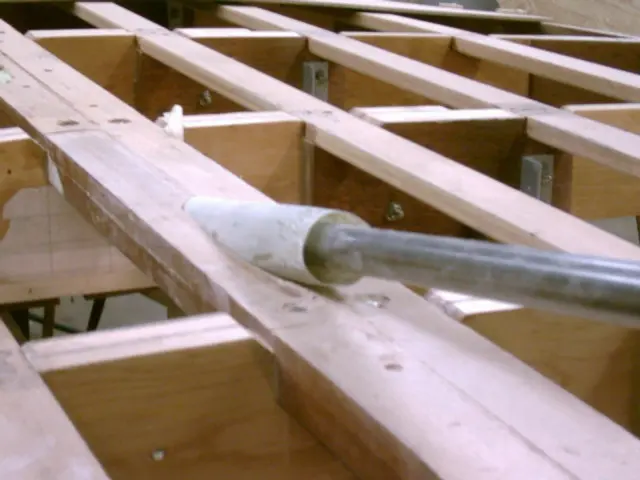
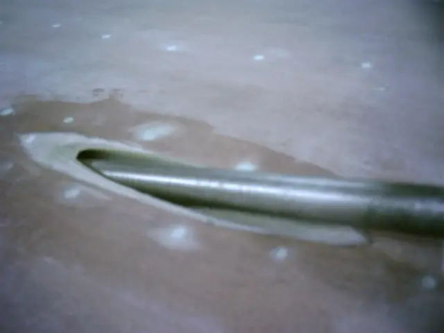
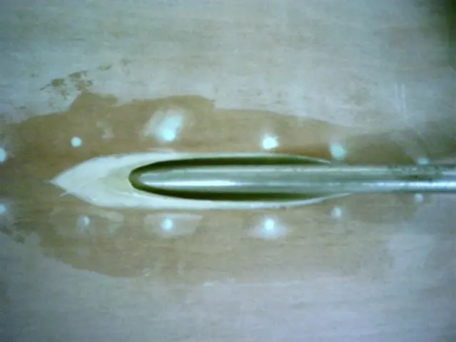
A fiberglass tube was inserted into the shaft hole
A fiberglass tube was inserted into the shaft hole. Click here to see how the tube was made.
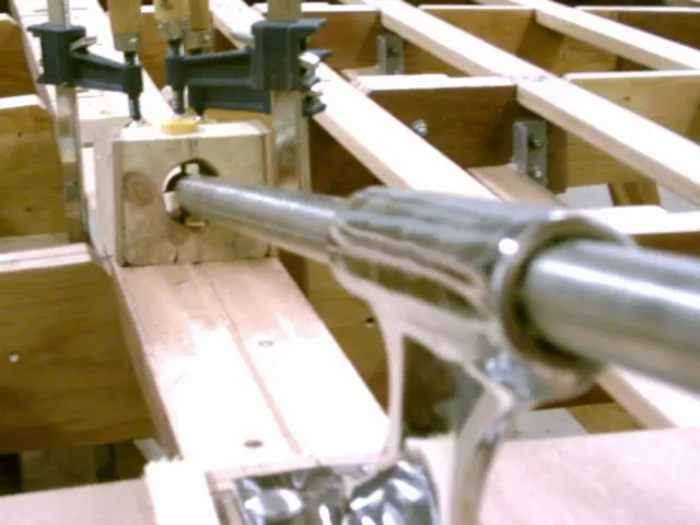
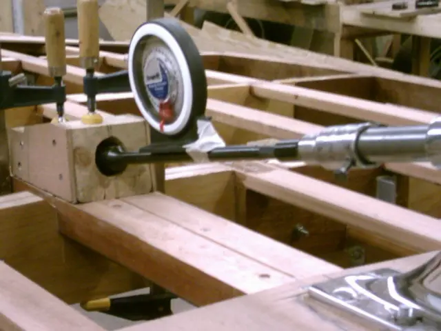
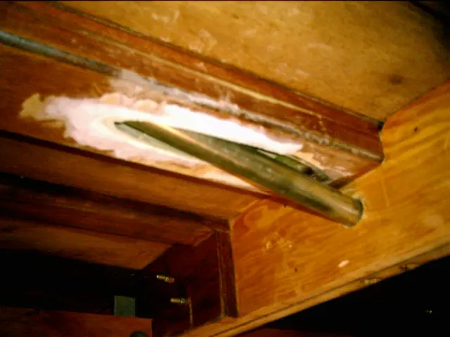
This is a view from inside the boat. An 8' long shaft was fed through the strut and shaft hole. A 1" hole was drlled in frame #4 to position the shaft at 12 degrees.
A 1" ID x 1-5/8" OD rudder shaft collar inserted into each end of the tube will center the shaft in the tube until the epoxy cures.. When the boat is righted, the tube will be ground flush with the keel. Two laminations of fiberglass cloth will be applied to the keel before installing the shaft log.
Photo quality should improve drastically from this point on
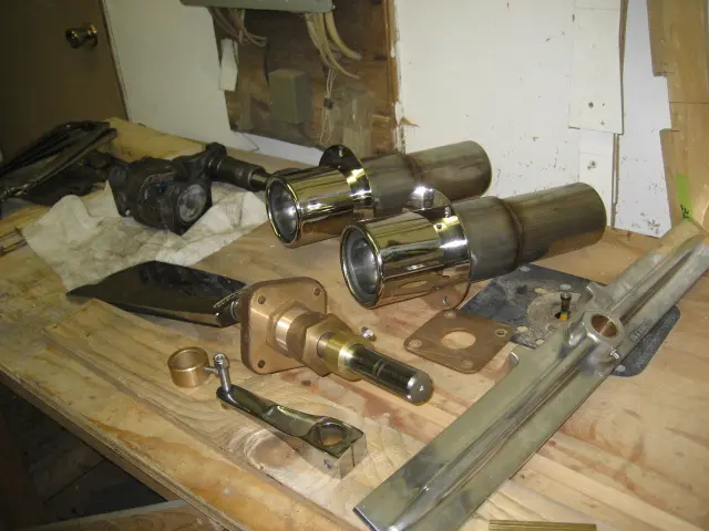
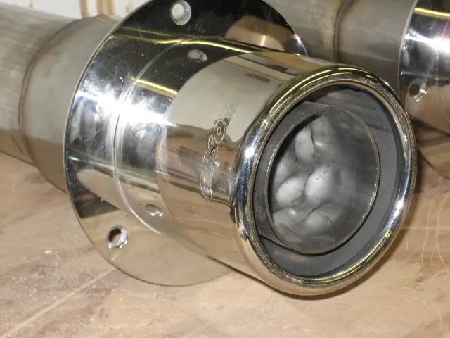
Photo quality should improve drastically from this point on. We bought a new Canon PowerShot SD600 digital camera. Hopefully the closeup and white color balance issues I had with the old camera are a thing of the past ! The rudder and rudder support bracket are back from the machine shop. 3-1/2" stainless steel pipe stubs were tig-welded to the Gibson Transom Mount mufflers. We also picked up a 1350 series Center H Yoke which will replace the torque tube.
These performance mufflers should be legal at idle. Can't wait to hear them when that 283 comes to life !
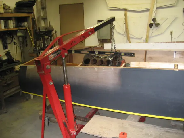
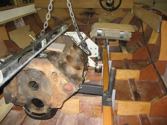
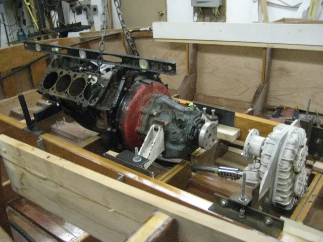
A bare-block 400 cubic inch V8 was bolted to the Velvet Drive transmission and hoisted into position.
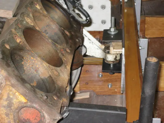
Temporary motor mounts provide up, down and side-to-side adjustment.
Found some vintage transmission mounts at Ayling's Boat Yard. They're stout pieces and fit better than the previous ones I had. A new set of stringer brackets is being fitted.
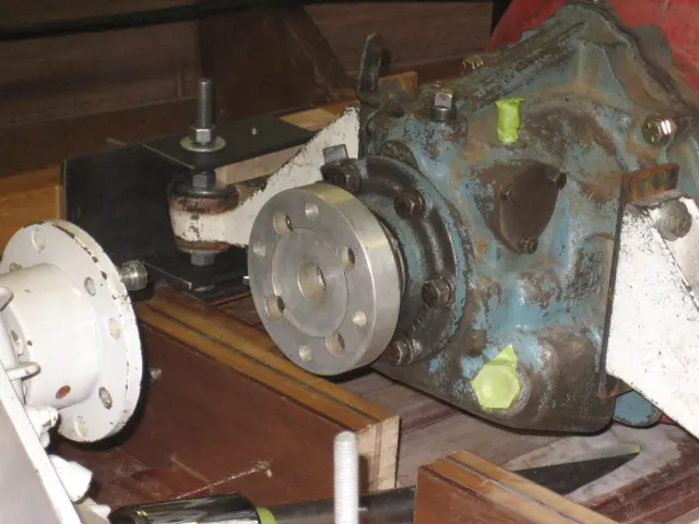
A 1350 series Borg Warner power takeoff (Glenwood Part # 90-797) is bolted to the Velvet Drive transmission's output shaft. Ratio is 1:1. The used Casale 12 degree v-drive with 15% overdrive was equipped with a 1350 series V-drive flange takeoff (Glenwood Part # 90-865).
Cutting into the oil pan (adjacent to the frame) moves the engine back far enough to install a 6-1/2" long H joint instead of the 10-1/2" long torque tube (Glenwood Part # 90-835) we initially thought would be used. This also drops the engine down 2" closer to the keel. To provide more oil capacity, a front sump and kicked-out sides will be added to the pan.