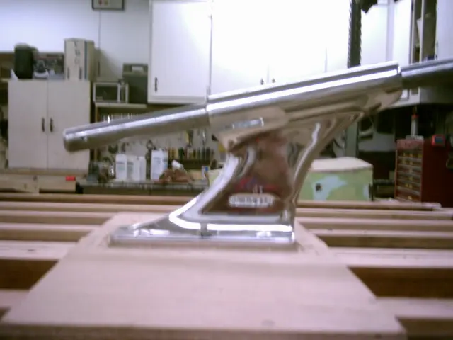
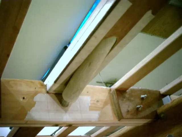
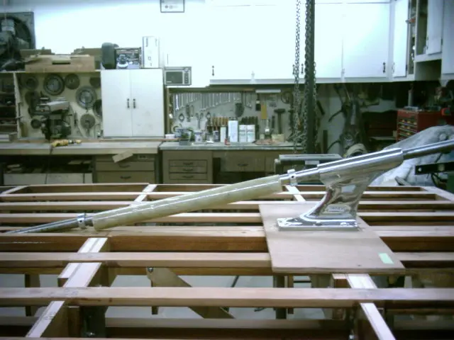
A 1/8" masonite spacer was fabricated and slipped under the strut to simulate the thickness of two layers of fiberglass
A 1/8" masonite spacer was fabricated and slipped under the strut to simulate the thickness of two layers of fiberglass cloth which will eventually cover the hull. The strut was bolted into position and an 8' long piece of 1" round bar was fed through the strut to simulate the propeller shaft.
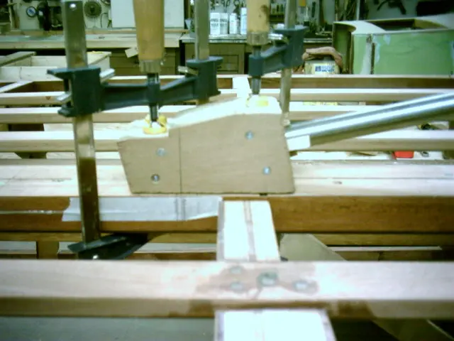
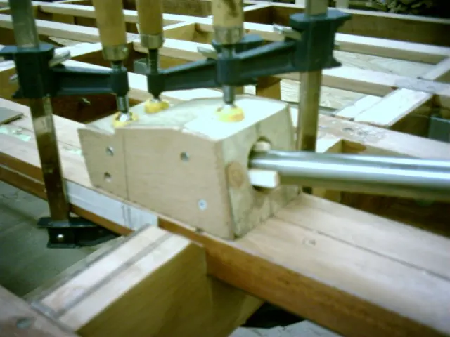
A guide block was loosely clamped to the keel. Click here to see how the guide was made.
Push the shaft through the guide block until it contacts the keel and mark the point. Shim the shaft until it's centered in the guide block and mark the holesaw entry point. Clamp the guide block.
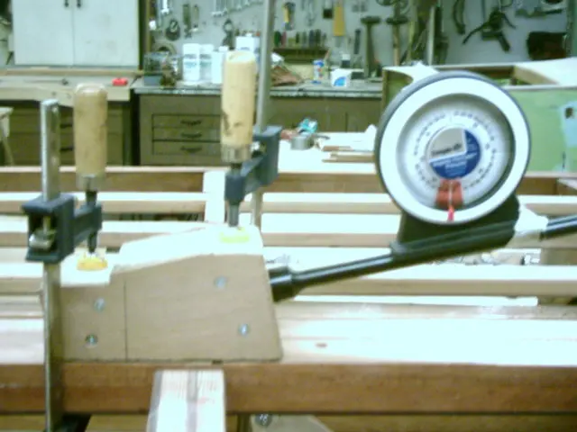
Remove the shaft and insert the boring bar, coupler and holesaw into the guide block. Use an inclinometer to verify the shaft angle is correct before drilling.
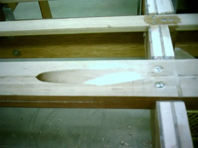
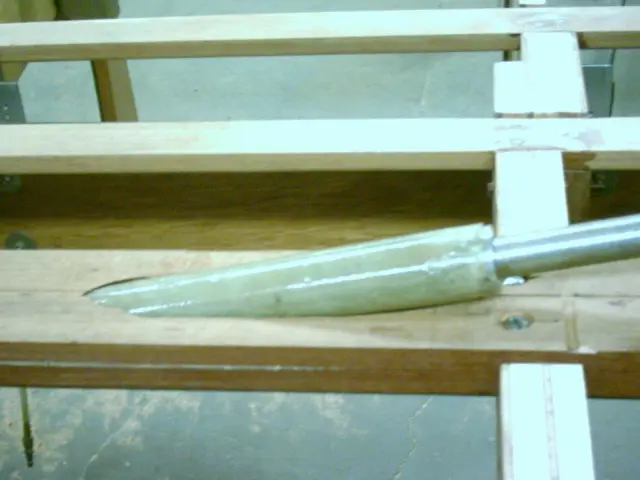
A fiberglass tube was inserted into the shaft hole
A fiberglass tube was inserted into the shaft hole. Click here to see how the tube was made.
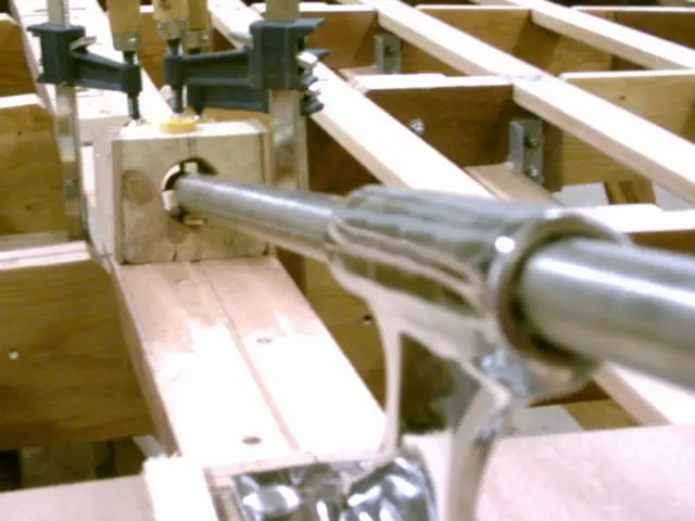
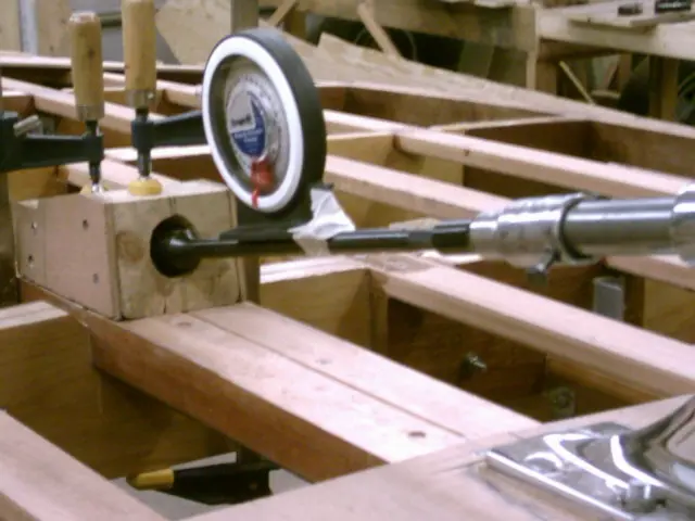
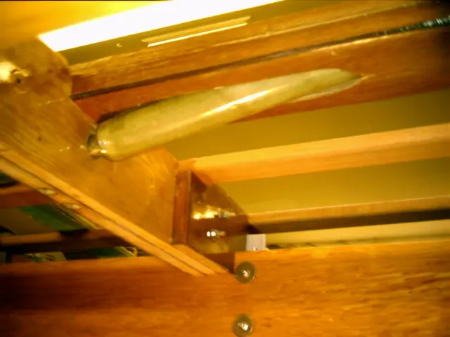
This is a view from inside the boat. An 8' long shaft was fed through the strut and shaft hole. A 1" hole was drlled in frame #4 to position the shaft at 12 degrees.
A 1" ID x 1-5/8" OD rudder shaft collar inserted into each end of the tube will center the shaft in the tube until the epoxy cures.. When the boat is righted, the tube will be ground flush with the keel. Two laminations of fiberglass cloth will be applied to the keel before installing the shaft log.
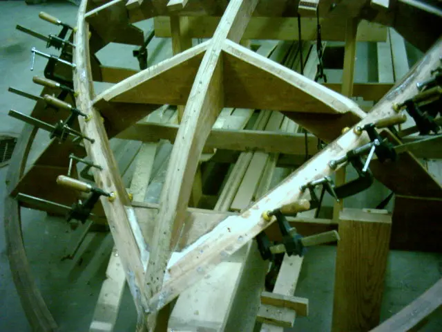
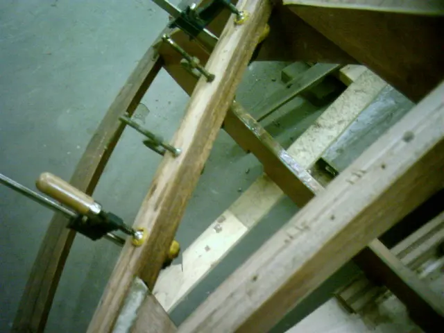
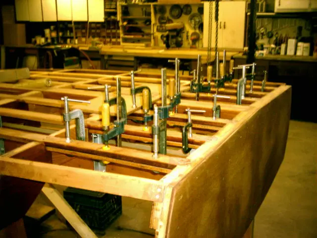
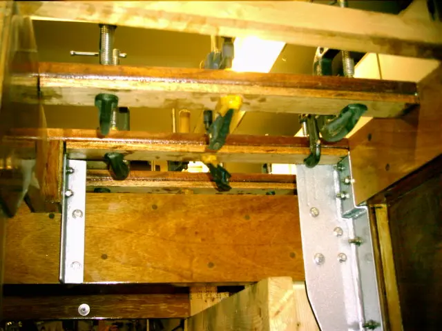
Two layers of 3/8" thick by 2" wide mahogany stock were laminated to the inside chine log surfaces
Two layers of 3/8" thick by 2" wide mahogany stock were laminated to the inside chine log surfaces. This will restore some strength to the members, lock the frames into position and provide additionnal fastening area for the first plywood bottom screws.
A 3/8" thick lamination was added to the rear battens. We'll be cutting 3/8" deep limbers (drainage channels) so additional material must be provided to maintain the batten's integrity.
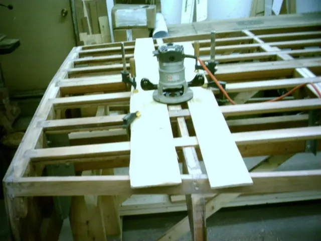
A quick and accurate method of fairing the frames so they'll sit 1/8" below the battens involves running a router over t
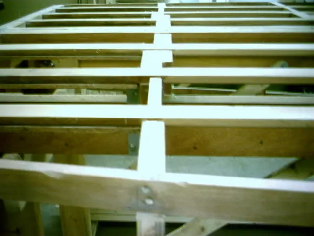
A quick and accurate method of fairing the frames so they'll sit 1/8" below the battens involves running a router over two strips of 1/4" plywood clamped to the battens.
This prevents 'hard spots' from forming on the hull where the frames contact the bottom planking.
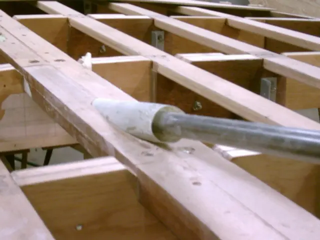
The strut was reinstalled and an 8' long piece of 1" round bar was slipped into it
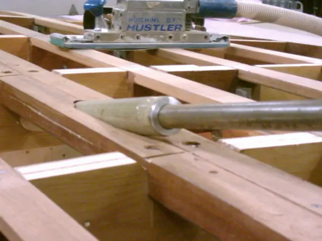
The strut was reinstalled and an 8' long piece of 1" round bar was slipped into it. Two 1" ID by 1-5/8" OD bushings and the fiberglass tube were slid onto the shaft.
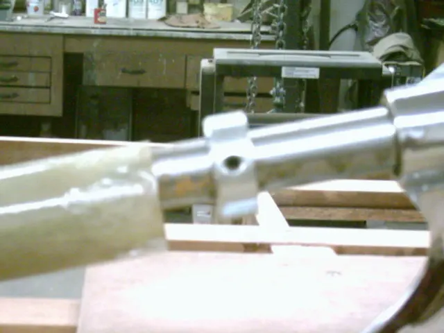
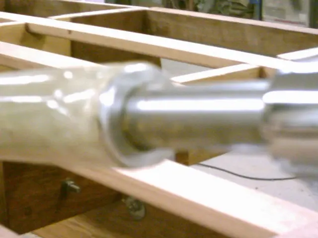
Here's a closeup shot of the tube and bushing.
The bushings were slid into each end of the tube. This will ensure that the tube is centered on the shaft.
The assembly is pushed into the shaft hole. It should be a loose fit. Enough clearance for a coat of thickened epoxy around the tube will be required. If the fit is too tight or if the tube binds in the shaft hole, roll and tape a piece of coarse sandpaper around the tube and rotate it in the shaft hole.
Here's the view from inside the boat. The 1" shaft rests in a 1" diameter hole drilled into the frame at a 12 degree angle. You can also see the fiberglass tube bushing.