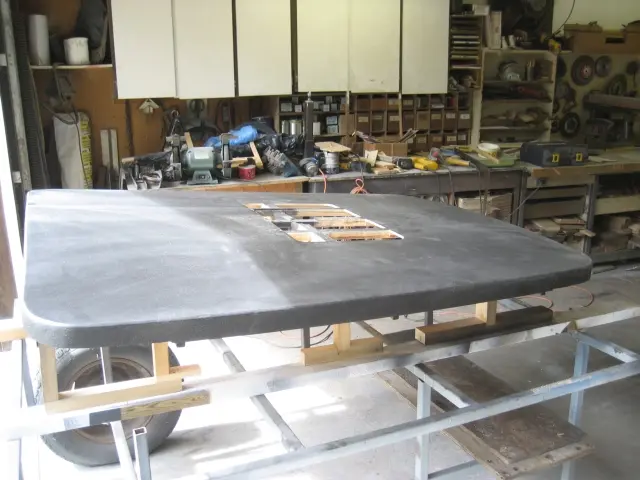
Tonneau cover: The first round of primer surfacer was applied
The first round of primer surfacer was applied.
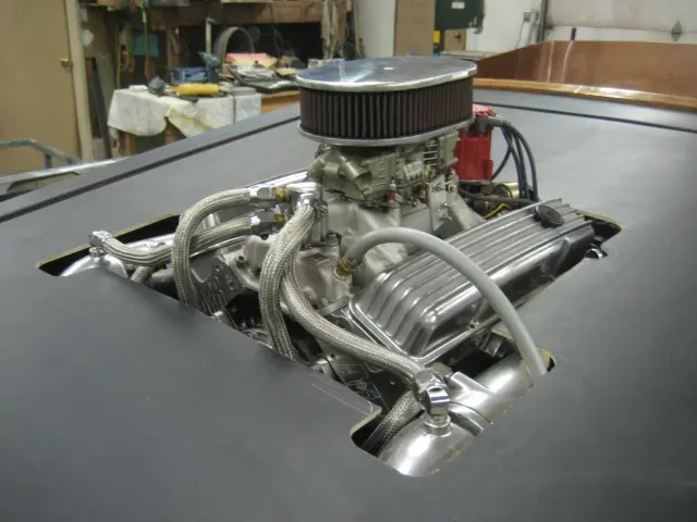
Some of the cover was cut out for the engine opening. We won't be doing the final trimming until the engine is installed.
Hot Rod · new build
LaunchedThe first round of primer surfacer was applied.
Some of the cover was cut out for the engine opening. We won't be doing the final trimming until the engine is installed.
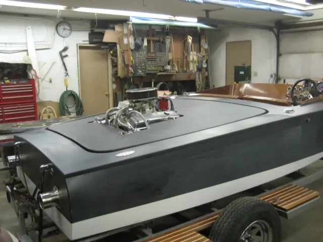
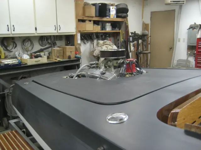
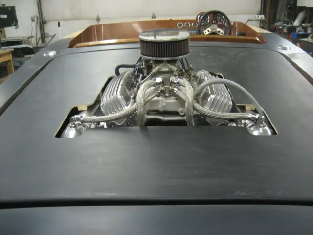
1. Here are a few photos after trimming the tonneau cover to fit around the engine. Still lots of trimming to do, but it certainly has the look I had envisioned ! It's going to be sweet !
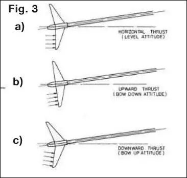
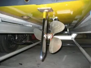
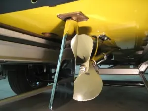
Steeper shaft angles increase upward thrust which increases transom lift and decrease bow lift. Lower shaft angles reduce upward thrust and increase bow lift. More thrust is available to propel the boat. Reference : Basic Propeller Theory - Prop Shaft Angles (sfmbc.net)
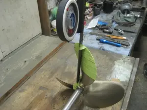
How to measure propeller rake The Rake measurement indicates the angle of blades tilt towards or away from the transom. The rake angle is measured on a line extending from the center of the hub through the center of one blade. A propeller with 0 degree rake has blades 90 degrees perpendicular to the center of the hub. A 20 degree rake results in a blade that is angled 70 degrees from the hub.
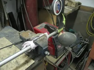
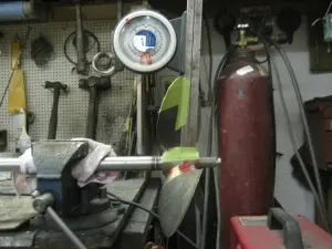
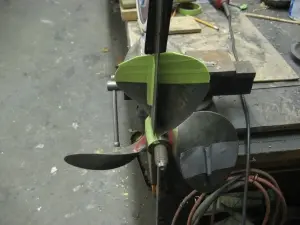
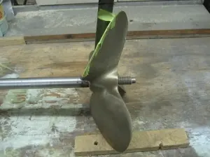
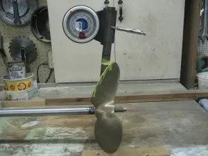
Propeller is mounted to a propeller shaft and levelled horizontally in a bench vise.
Rake is the measurement of the angle of the tilt of the blade's tip toward or away from the propeller's front hub face. The angle is measured on a line extending from the center of the hub through the center of one blade.
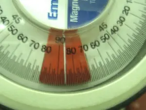
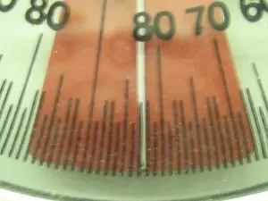
An inclinometer (angle finder) is used to find the rake angle. The setup presented here isn't very accurate, but will work if you need a quick determination of rake angle when you're in the field.
Here's our new OJ 12x16p LH 3 blade Nibral propeller.
Propeller # 1 is a 12" diameter by 15" pitch left hand rotation propeller.
Propeller # 2 is a Menkens 11-1/2" x 15p forged steel 2-blade. We encountered severe ventilation and vibration with this propeller.

1. The sensors are only installed when we wish to check the carburetor's calibration after we've made jetting changes. A stainless steel oil pan drain plug is installed when the sensors are not needed.
2. Sensor fitted to the first cylinder bank...
3. ... and the second cylinder bank.
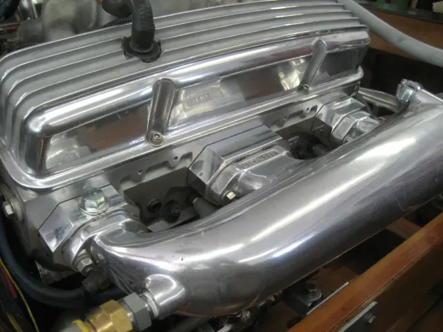
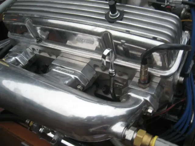
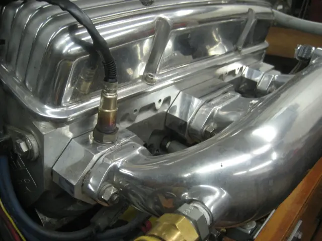
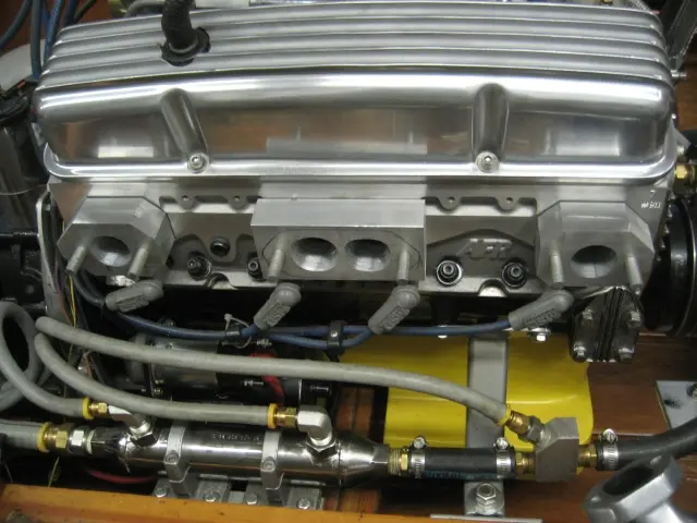
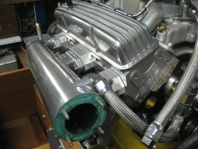
To help tune our carbureted engine, we fabricated aluminum spacer blocks to mount a wideband oxygen sensor in each cylinder bank as close to the exhaust ports as possible. The sensors will feed an air-fuel meter which will indicate if the air-fuel mixture is rich or lean. The spacer blocks are prototypes for an automotive TBI to marine conversion kit that we've been working on. We'll have more on that project as soon as its up and running !
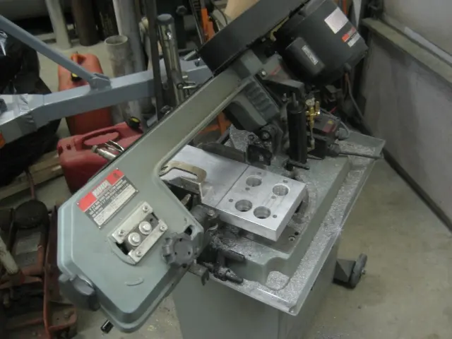
1. We fabricated a set of exhaust manifold spacers from 1-1/2" thick aluminum stock.
2. The original allen head cap bolts were replaced with studs.
3. The spacers will be drilled and tapped to accept a wideband oxygen sensor.
Nobody else here is logging a Hot Rod yet. See the boat.