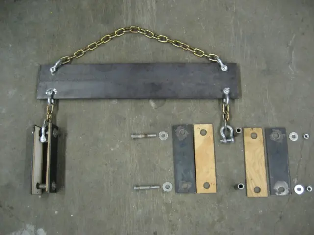
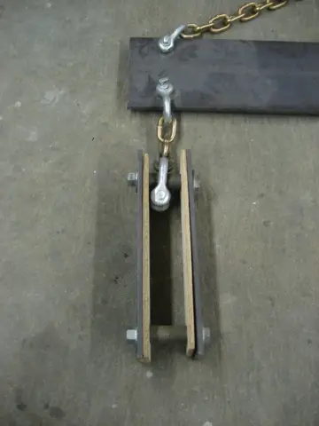
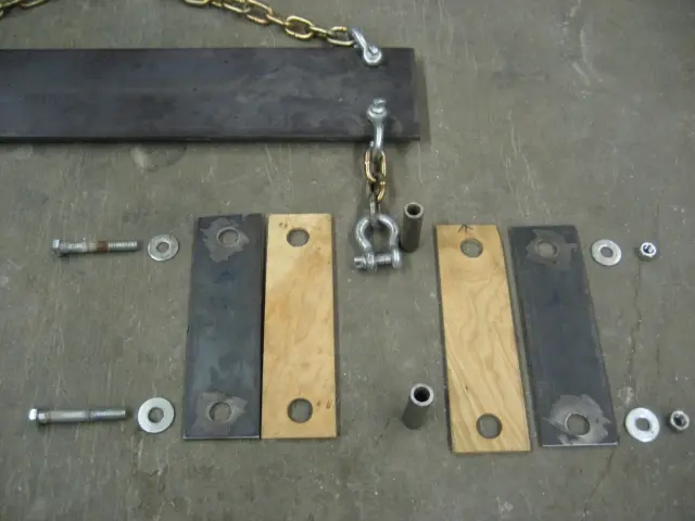
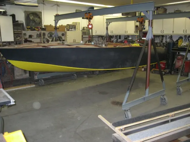
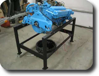
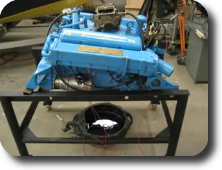
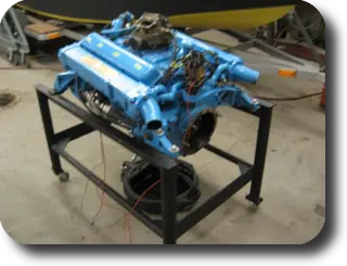
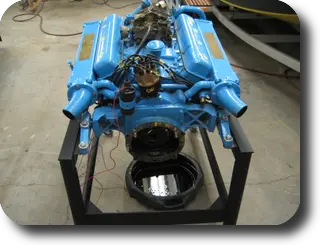
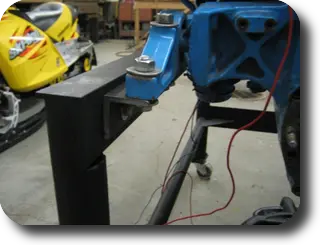
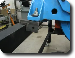
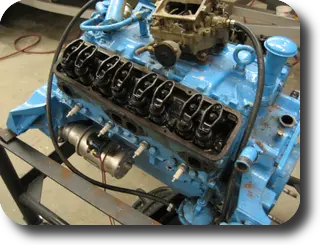
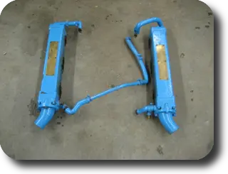
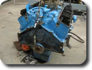
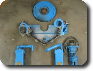
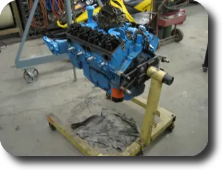
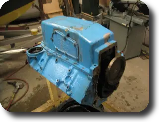
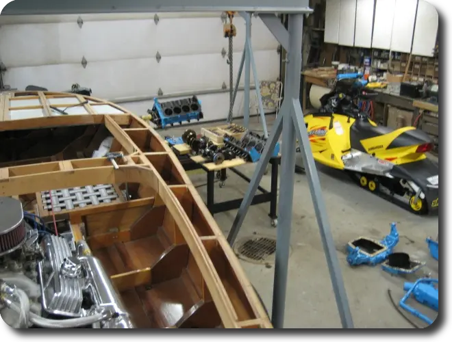
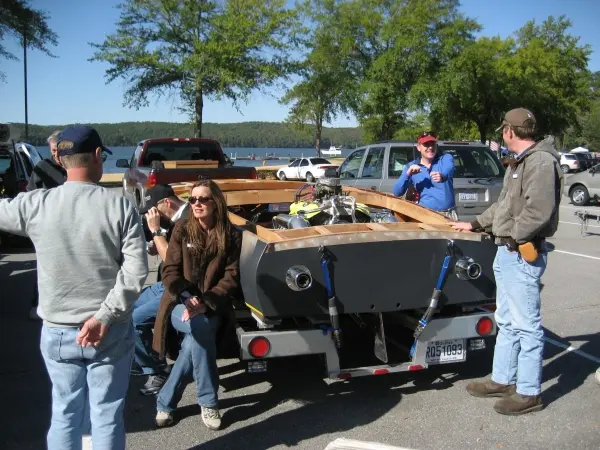
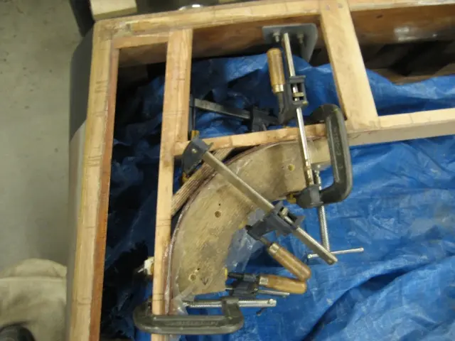
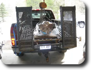
These photos depict how the front and rear cover support brackets were mounted to the engine stand. In the background you'll see that the boats and engines have to share the shop with other toys. That's our Snow Hot Rod , a 2003 Rev 600 HO. Two cylinder, 597cc two-stroke, 114 HP, 8000 RPM, 90+ MPH ... On a nice day like today we really should be riding the trails but we have to get these boats up and running for next Summer ! A compression test was run before disassembling the engine. Here's what we found : Cylinder # Compression PSI Cylinder # Compression PSI 8
Overall, we're looking at a very well used engine ! Normal compression pressure readings should be 140 to 150 PSI. The really low numbers indicate serious problems with the valves or worn piston rings and cylinder bores. A rebuild should restore the engine back to it's former power level. If the cylinder walls are badly scuffed or scored, or if they are out of round or tapered beyond the limits given in the specifications for your engine, the engine block will have to be rebored and honed at an automotive machine shop. If a rebore is done, oversize pistons and rings will be required.
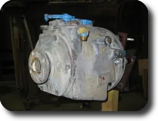
1. Industrial duty paint stripper was used to strip several coats of paint from the transmission. The next day, we took the unit out to Steve Flewitt at Ayling's Boat Yard in Merrickville, Ontario for rebuilding.
2. We've always wanted to build an engine break-in stand, so we took the time to build a custom unit for this engine. We'll be able to hook up and test run the engine after it's rebuilt. Breaking in a new camshaft requires running the engine at 2500 to 3000 RPM for half an hour or more, so we decided to fabricate removable caster wheels to ensure that the unit doesn't start walking away on us while it's running. The casters are bolted to a flat plate welded to a short length of pipe inserted into each leg.
3–5. To accommodate steep propeller shaft angles, the Chris-Craft engineers produced several proprietary parts to reduce the length and height of their drivetrains. Notice that the engine has been turned 180 degrees so that the flywheel is facing the bow and the distributor, which is usually mounted ahead of the flywheel, has been relocated to the front of the engine. To provide adequate engine hatch clearance, they produced a low-profile intake manifold which incorporates a built-in 15 degree carburetor mounting flange. The Chris-craft engineers also used gear driven camshafts to reverse the engine rotation on selected models. They didn't use standard Chevrolet cylinder numbering schemes preferring to use their own numbering scheme and firing orders. Your best bet is to refer to the appropriate Chris-Craft Service Manual for application specific information. To order these manuals, see the link under Service Manuals in the Related Links and References section at the end of this article.
6–7. These photos depict how the front and rear cover support brackets were mounted to the engine stand. In the background you'll see that the boats and engines have to share the shop with other toys. That's our Snow Hot Rod, a 2003 Rev 600 HO. Two cylinder, 597cc two-stroke, 114 HP, 8000 RPM, 90+ MPH... On a nice day like today we really should be riding the trails but we have to get these boats up and running for next Summer !
8. It's 9 AM, Saturday, February 7 2009 and we've got a lot of work to do ! First step is to remove the exhaust manifolds.
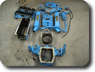
9. We're running out of room to store all these parts, so we'll spread everything out on the shop floor and pick up the pieces later !
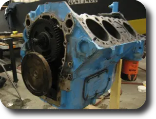
10. We lifted the engine from the engine stand and set it on the floor to disassemble the flywheel and front cover. Note that this is a flywheel forward engine, so the Chris-Craft Part Book refers to it as a front cover and support bracket.
11. The flywheel and front cover have to be removed simultaneously because of the starter and water pump mounting 'ears' on each side of the cast aluminum cover.
12. With the front cover removed, we can re-install the engine onto an engine assembly stand.
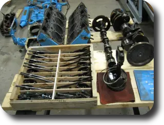
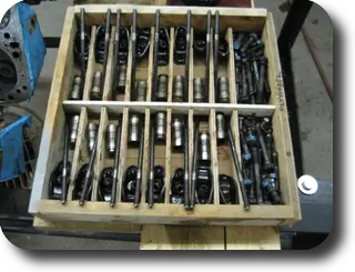
13. Valvetrain components were removed and placed in a parts organiser tray. Another homebuilt tool ! This will ensure that the components are returned to their original location. Increased wear on these components will occur if they're just dumped into a box and re-installed in no particular order.
14. Knowing which cylinder the part was removed from is helpful. While inspecting the parts, you can relate any lifter wear patterns to the corresponding camshaft lobes and lifter bores.
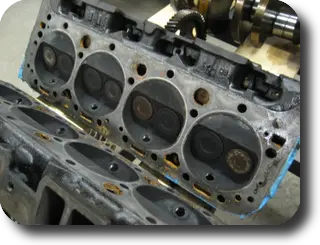
15. No major issues with the cylinder heads. We had to resort to using a 6 foot long breaker bar to lever them off the cylinder block ! Nothing about this procedure in the engine assemply book...
16. Here's what's hiding under the rear cover. The Chris-Craft Part Book refers to it as a rear cover and support bracket.
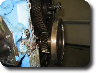
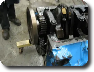
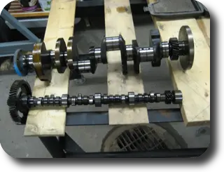
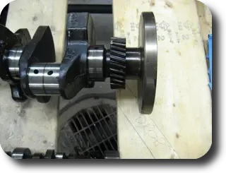
17. Gear driven reverse rotation camshaft. The small spur gear on the end of the camshaft drives the distributor. The large disc at the bottom of the photo is press-fit onto the crankshaft. The transmission drive plate bolts to this disc.
18. A few more bolts and the oil pan can be removed. Note the large inspection cover bolted to the side of the pan. In an effort to prevent oil pump cavitation when getting the boat on plane, the flywheel forward Chris-Craft engines have relocated the oil pickup assembly to the front of the pan. The side cover will have to be removed to disconnect the flexible braided stainless steel hose connecting the pickup to the oil pump.
19. We've added the rear cover (bottom of photo), oil pan and cylinder heads to our parts pile.
20. Here's another photo of the crankshaft-mounted camshaft drive gear and transmission drive plate disc.
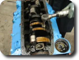
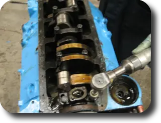
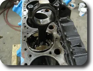
21. The piston / connecting rod assemblies can be pulled from the engine once the connecting rod cap bolts have been removed.
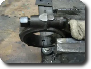
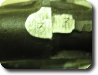
22. To ensure that the connecting rods and caps don't get mixed up, a numbered punch set is used to emboss the cylinder number for each connecting rod and rod end cap.
23. Numbers are pretty faint but legible.
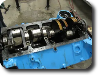
24–25. Once the main bearing caps are removed, the crankshaft can be lifted from the block.
26–27. The forged steel crankshaft will require some machining to remove minor scratches on the connecting rod and main bearing journals. The gear-driven camshaft is a reverse-rotation solid lifter design which requires valve lash adjustment every 100 hours of use. We may replace it with a hydraulic lifter unit which will require less maintenance and run a little quieter.
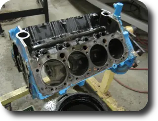
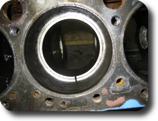
28. We're finally down to the bare block !
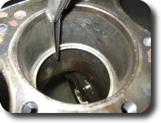
29. A rough estimate of cylinder bore wear can be derived by removing a top compression ring from one of the pistons and inserting it into the cylinder bore. We've chosen to measure the cylinder which posted the lowest compression pressure (# 4 at 35 PSI).
30. Photo 1
31. Photo 2
Measure the piston ring end gap by first squaring the piston ring within the cylinder bore by turning a flat-top piston upside down in the bore ( Photo 1 ). The ring gap should be measured at 90 degrees to the piston pin ( Photo 2 ). The piston 'slap' face side of the bore receives more wear than the area adjacent to the piston pin. Measure piston ring end gap with a feeler gauge. Start small and use progressively thicker gauges until a snug fit is obtained. Normally you'd measure the cylinder bore at several locations namely 1/2" from the top, middle and close to the bottom. The feeler gauge method only reports piston ring end gap so any variance will correspond to the amount of cylinder bore wear. Comparing your measurement to the piston ring end gap specification will tell you how much the rings and cylinder bore have worn.
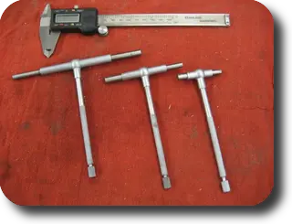
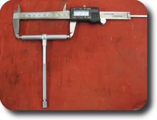
32. Although not required for this type of measuring, a telescopic gauge and a digital caliper will speed up the measuring process.
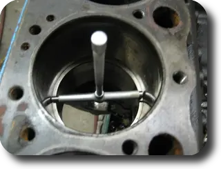
33. Once the piston ring is squared up in the bore, the telescopic gauge can be dropped into the bore until it contacts the ring. Tightening the gauge's knurled stem mechanism locks in the measurement.
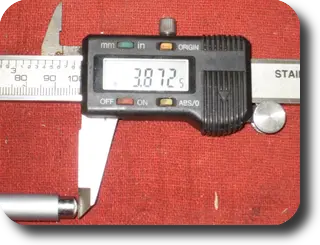
34–35. The digital caliper is used to measure the telescopic gauge. This is much faster than messing around with feeler gauges ! We didn't have to measure too many cylinder bores to come to the conclusion that the engine block will have to be rebored, honed and fitted with new oversize pistons and rings. All cylinders were worn well beyond the manufacturer's taper limit. We'll ship all the parts to the machine shop and wait for an estimate.
36. It's 2 PM and we're done for the day on this particular job. We'll stop for lunch and get back to finalizing the Hot Rod 's transmission shifter linkage. Remember all those parts on the floor ? We'll have to scrape all the gasket surfaces and clean the parts thoroughly. Too bad Bruce wasn't here to share in the fun... come to think of it, now I know why he's smiling in that photo of us pulling the drivetrain from his boat ! That's all for this installment. I hope you've enjoyed the photos. We'll see you in a few weeks when we reassemble everything !