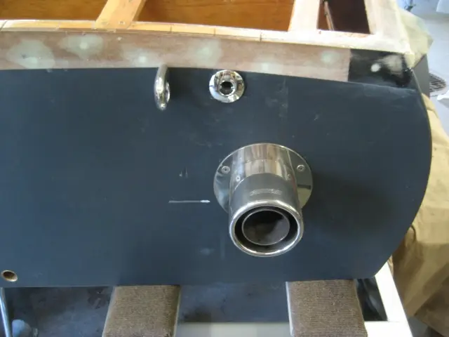
Jump seats and fuel tank: A 1-1/8" hole saw was used to install the two bilge pump thru-hulls
Hose barb will take a 3/4" hose. Also visible in this photo are the two 3/8" annealed copper tubing hydraulic steering hoses. They're retained by bulkhead fittings bolted through the steel transom support uprights.
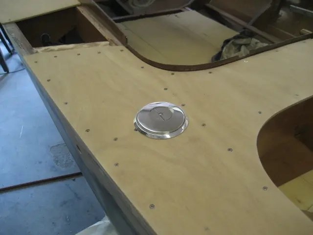
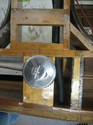
... and the fuel fill hose.
1. A 1-1/8" hole saw was used to install the two bilge pump thru-hulls.
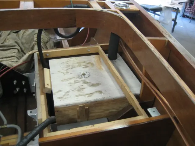
2. The large white box is a plywood mockup of a 9.5 gallon fuel tank. A 2" fuel fill hose can be seen on the right of the photo. A 5/8" fuel vent hose with a high coiled loop is on the left.
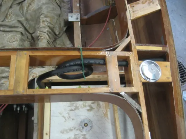
3. Here's a better view of fuel vent hose...
4. The vent hose was routed to the sheer. Hose should be run 'downhill' so that water can't find its way back into the tank.
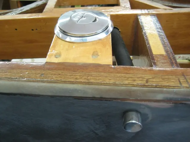
5. Stainless steel fuel vent fitting completes the fuel tank rigging ! We'll be taking our fuel tank mockup into a welding shop next week !
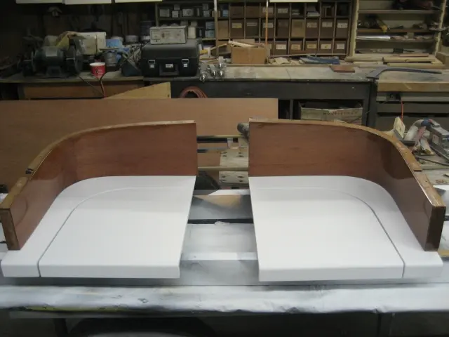
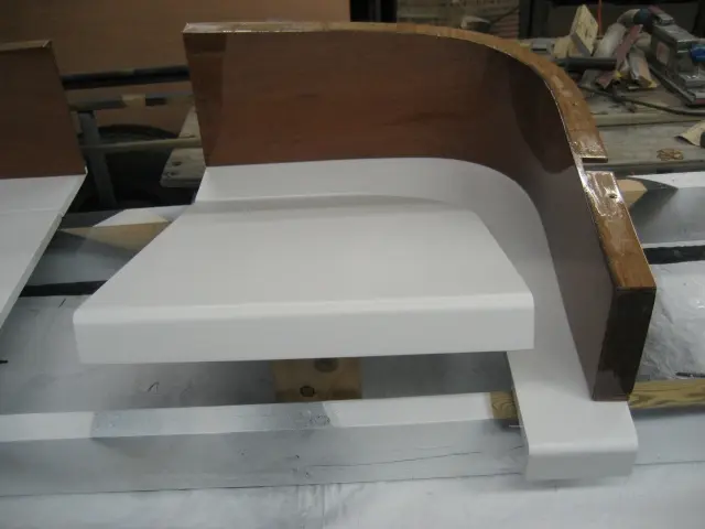
Jump seats and fuel tank: We built up the jumpseat's leading edge with a piece of 1" x 2" stock and radiused the top
1. We built up the jumpseat's leading edge with a piece of 1" x 2" stock and radiused the top edge before laminating both sides with 10 ounce fiberglass cloth.
2. A stainless steel piano hinge will complete the assembly.
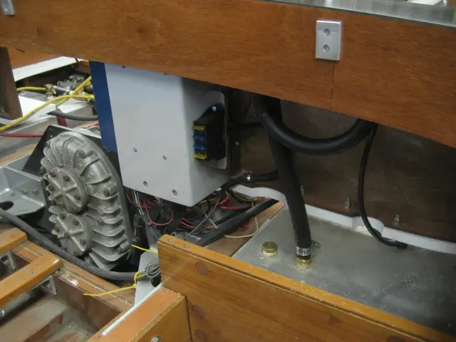
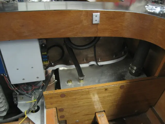
Jump seats and fuel tank: The 5/8" rubber fuel vent hose has been looped to form a high loop before its routed to th
1. The 5/8" rubber fuel vent hose has been looped to form a high loop before its routed to the sheer mounted fuel vent fitting.
2. The 2" fuel fill hose is directly below the deck fill fitting.
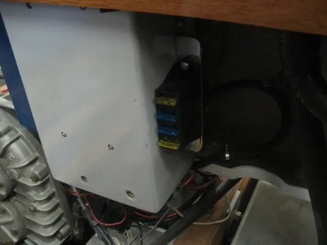
3. Here's a closeup shot of the unswitched 12 volt fuse block. This provides circut protection for the automatic bilge pump and any accessories that require unswitched 12 volt power.
123
Nobody else here is logging a Hot Rod yet.
See the boat.